

Siemens SIMATIC S5 ET 200U User Manual

System Overview
1
ET 200U
Distributed I/O Station
Manual
Technical
Description
Mechanical and Electrical
Configuration
ET 200U(DP Siemens):
Address Assignment, Starting
Up, Diagnosing Faults
ET 200U(DP Standard):
Address Assignment, Starting
Up, Diagnosing Faults
ET 200U(DP Standard/FMS):
Modes, Settings and Comm.
Cap. of the IM 318–C
Analog Value Processing
Module Spectrum
2
3
4
5
6
7
8
Function Modules
Safety–Related
Guidelines
Glossary
9
A
B
Edition 03
EWA 4NEB 812 6087–02b

SIMATIC and SINEC are registered trade marks of Siemens AG.
Safety–related
Guidelines
!
!
!
This manual contains notices intended to ensure personal safety, as well as to protect
the products and connected equipment against damage. These notices are highlighted
by the symbols shown below and graded according to severity by the following texts:
Danger
indicates that death, severe personal injury or substantial property damage will result
if proper precautions are not taken.
Warning
indicates that death, severe personal injury, or substantial property damage can result
if proper precautions are not taken.
Caution
indicates that minor personal injury or property damage can result if proper precautions are not taken.
Note
contains important information about the product, its operation or a part of the document to which special attention is draw.
Qualified
Personnel
Proper
Usage
!
Exclusion of Liability
We have checked the contents of this manual for agreement with the
hardware and software described. Since deviations cannot be precluded entirely, we cannot guarantee full agreement. However, the
data in this manual are reviewed regularly and any necessary corrections included in subsequent editions. Suggestions for improvement
are welcomed.
Technical data subject to change.
A device/system may only be commissioned or operated by qualified personnel.
Qualified personnel as referred to in safety guidelines in this document are persons
authorized to energize, de–energize, clear, ground, and tag circuits, equipment and
systems in accordance with established safety practice.
For a detailed description of the safety–related guidelines, please refer to the Appendix.
Please observe the following:
Warning
The equipment/system or the system components may only be used for the applications described in the catalog or the technical description, and only in combination
with the equipment, components, and devices of other manufacturers as far as this is
recommended or permitted by Siemens.
The product will function correctly and safely only it it is transported, stored, set up,
and installed as intended, and operated and maintained with care.
Copyright
Copyright Siemens AG 1993 All Rights Reserved
The reproduction, transmission or use of this document or its contents
is not permitted without express written authority. Offenders will be
liable for damages. All rights, including rights created by patent grant
or registration of a utility model or design, are reserved.
Preface
The ET 200U distributed I/O station belongs to the ET 200 distributed I/O
system with the SINEC L2–DP field bus.
Available Bus Protocols
Prerequisites
Scope of this
Manual
The distributed I/O station operates with the DP Siemens, DP Standard and
FMS protocols.
The DP Siemens bus protocol has been developed by Siemens especially for
the ET 200 distributed I/O system.
The DP standard bus protocol, a further development of DP Siemens, complies with the PROFIBUS–DP draft standard (DIN 19245, Part 3), the
PROFIBUS solution for high–speed field applications.
FMS is the PROFIBUS bus protocol described in DIN 19245, Part 2.
This manual is based on the “ET 200 Distributed I/O System” Manual.
The manual is structured as follows:
What is ET 200U?
Which control and display
elements does the ET 200U have?
How is the ET 200U installed?
Chapter 1
Chapter 2
Chapter 3
ET 200U Distributed I/O Station
EWA 4NEB 812 6087–02b
How is the ET 200U (DP Siemens)
started up with COM ET 200?
How is the ET 200U (DP Standard)
started up with COM ET 200?
ET 200U (DP Standard/FMS):
How is an IM 318–C operated?
Analog value processing
T echnical specifications
+
list of I/O modules
Chapter 4
Chapter 5
Chapter 6
Chapter 7
Chapters 8 + 9
iii

Preface
Contents of this
Manual
”318–8MB11”
”318–8MB12”
This manual describes the IM 318–B slave interface module with order numbers:
6ES5 318–8MB11
6ES5 318–8MB12
6ES5 318–8MC11
An interface for SINEC L2–DP with DP Siemens protocol is integrated in the
“318–8MB11”.
Note
The “318–8MB11” module is operated in conjunction with
COM ET 200 (from version 1.0) and
IM 308–B (from revision level 1)
The functionality of the “318–8MB11” module is a subset of the functions of
the “318–8MB12”.
Additionally , the “318–8MB12” operates in accordance with the
PROFIBUS–DP (DIN 19245/Part 3) draft standard, in the following referred
to as DP Standard.
The draft standard will be explained in detail in Section 1.3.
Note
A “318–8MB12” module can be operated as DP Standard slave (ET
200U(DP Standard) in conjunction with
COM ET 200 (from version 4.0) and
IM 308–B from revision level 5 (printed on module) or software
version 4.0 (indicated in COM ET 200).
ET 200U Distributed I/O Station
iv
EWA 4NEB 812 6087–02b

Preface
“318–8MC11”
An interface for SINEC L2–DP (DP Standard) and SINEC L2–FMS is integrated in the “318–8MC11”.
The “318–8MC11” can be addressed via the same bus both with the DP Standard and FMS protocols.
Note
An “318–8MC11” can be operated as DP Standard slave in conjunction with
COM ET 200 (from version 4.0) and
IM 308–B from revision level 5 (printed on module) or from software
version 4.0 (indicated in COM ET 200).
A “318–8MC11” module can be operated as an FMS slave on any bus type
conforming to the PROFIBUS DIN 19245 standard, Parts 1 and 2.
If the DP and FMS protocols are used on the bus at the same time, a maximum of two DP masters, one FMS master (additional active station) and one
programmer are permitted.
Notes for Conversion from “8MB11”
to “8MB12”
Table 1-1 Differences between the IM 318–B slave interface modules
In the following table, the differences between the 6ES5 318–8MB12 and the
6ES5 318–8MB11 modules are listed.
Difference Described in ...
Pulling and plugging–in of I/O modules under load voltage is only
Chapter 3
permitted under defined conditions.
Depending on whether the “DP Siemens” or the “DP Standard” proto-
col is used, COM ET 200 requires different address identifiers for the
T able 4-1, Section 4.1.1 and
T able 5-1, Section 5.1.1
modules.
Different functions of switch 8 (SLOW mode). Section 4.2.1 and Section
5.2.1
Different behaviour when exiting from the SYSTEM START–UP/
Section 4.2 and Section 5.2
TEST: MODULE SELECTION screen.
Different COM ET 200 screens for:
SYSTEM START–UP/TEST
DIAGNOSTICS
The three ET 200U interface modules have different manufacturer
identifications.
Section 4.2 and Section 5.2
Section 4.3 and Section 5.3
Section 4.3.3 and Section
5.3.3
Extended diagnostics messages for the station status. Section 5.3.3
Using COM ET 200, the “422–8MA11” digital input module can now
T able 5-1, Section 5.1.1
also be entered as 16–channel input module or as 1–channel analog
input module.
Individual input of address IDs. Section 5.1
ET 200U Distributed I/O Station
EWA 4NEB 812 6087–02b
v

Preface
Conventions
!
This manual is organized in menu form to make it easier for you to find information. This means the following:
At the front of the manual is an overview page that lists the title of each
chapter. Following this page you will find a table of contents.
The individual chapters are marked with printed tabs.
At the beginning of each chapter is a table of contents for that chapter.
Each chapter has three level headings that are numbered.
Pages, figures, and tables are numbered separately for each chapter.
Following the table of contents you will find a list of the figures and
tables.
This manual employs specific structuring devices which will be explained to
you in the following.
Important information is marked specifically:
Warning
You will find the definitions for the terms “Danger”, “Warning” and “Caution” in the “Safety–Related Guidelines” on the page following the front
page.
Footnotes are marked with a raised number (e.g.
You will find the corresponding explanations in the lower margin of the
page.
1
) or a raised asterisk
(*)
.
Enumerations are marked with a black point () (as, for example, in this
list) or with a dash (–).
Instructions are numbered (e.g. “1”).
Cross–refer ences are indicated in the following way: “(see Section
7.3.2)” refers to Section 7.3.2.
Dimensions in drawings are indicated in “mm”.
Value ranges are indicated as follows: 17 to 21
You will find correction sheets at the end of the manual. Use them to indicate
any corrections or suggestions for improvement you might have. Send these
suggestions to us. They will help us to improve the next edition of the system
manual.
ET 200U Distributed I/O Station
vi
EWA 4NEB 812 6087–02b

Contents
1 System Overview 1-1. . . . . . . . . . . . . . . . . . . . . . . . . . . . . . . . . . . . . . . . . . . . . . . . . . . . . . . .
1.1 What is ET 200? 1-2. . . . . . . . . . . . . . . . . . . . . . . . . . . . . . . . . . . . . . . . . . . . . . . . .
1.2 What is ET 200U? 1-3. . . . . . . . . . . . . . . . . . . . . . . . . . . . . . . . . . . . . . . . . . . . . . . .
Components 1-3. . . . . . . . . . . . . . . . . . . . . . . . . . . . . . . . . . . . . . . . . . . . . . . . . . . .
Characteristics 1-3. . . . . . . . . . . . . . . . . . . . . . . . . . . . . . . . . . . . . . . . . . . . . . . . . . .
1.3 What is DP Siemens and DP Standard? 1-4. . . . . . . . . . . . . . . . . . . . . . . . . . . .
What is DP Siemens and DP Standard? 1-4. . . . . . . . . . . . . . . . . . . . . . . . . . . .
Differences between DP Siemens and DP Standard 1-4. . . . . . . . . . . . . . . . . .
What Does DIN 19245 Have to Offer? 1-4. . . . . . . . . . . . . . . . . . . . . . . . . . . . . .
What is FMS? 1-5. . . . . . . . . . . . . . . . . . . . . . . . . . . . . . . . . . . . . . . . . . . . . . . . . . .
Definition 1-5. . . . . . . . . . . . . . . . . . . . . . . . . . . . . . . . . . . . . . . . . . . . . . . . . . . . . . .
2 Technical Description 2-1. . . . . . . . . . . . . . . . . . . . . . . . . . . . . . . . . . . . . . . . . . . . . . . . . . . .
2.1 Design of the ET 200U Interface Module 2-2. . . . . . . . . . . . . . . . . . . . . . . . . . . .
2.2 Technical Specifications 2-4. . . . . . . . . . . . . . . . . . . . . . . . . . . . . . . . . . . . . . . . . . .
Spectrum of I/O Modules 2-4. . . . . . . . . . . . . . . . . . . . . . . . . . . . . . . . . . . . . . . . . .
3 Mechanical and Electrical Configuration 3-1. . . . . . . . . . . . . . . . . . . . . . . . . . . . . . . . . .
3.1 Mechanical Configuration of the ET 200U Distributed I/O Station 3-2. . . . . . .
Installation, Dismantling 3-2. . . . . . . . . . . . . . . . . . . . . . . . . . . . . . . . . . . . . . . . . . .
Installing One Tier 3-3. . . . . . . . . . . . . . . . . . . . . . . . . . . . . . . . . . . . . . . . . . . . . . . .
Installing PS 931 Power Supply Module 3-4. . . . . . . . . . . . . . . . . . . . . . . . . . . . .
Installing PS 935 Power Supply Module 3-4. . . . . . . . . . . . . . . . . . . . . . . . . . . . .
Installing Bus Units 3-5. . . . . . . . . . . . . . . . . . . . . . . . . . . . . . . . . . . . . . . . . . . . . . .
Installing an I/O Module on a Bus Unit 3-6. . . . . . . . . . . . . . . . . . . . . . . . . . . . . .
Dismantling 3-7. . . . . . . . . . . . . . . . . . . . . . . . . . . . . . . . . . . . . . . . . . . . . . . . . . . . .
Expanding an ET 200U Slave Station to Several Tiers 3-9. . . . . . . . . . . . . . . .
Addressing with Multi–Tier Configuration 3-11. . . . . . . . . . . . . . . . . . . . . . . . . . . .
3.2 Wiring the ET 200U Distributed I/O Station 3-12. . . . . . . . . . . . . . . . . . . . . . . . . .
Wiring Methods 3-12. . . . . . . . . . . . . . . . . . . . . . . . . . . . . . . . . . . . . . . . . . . . . . . . . .
Screw–Type Connections 3-12. . . . . . . . . . . . . . . . . . . . . . . . . . . . . . . . . . . . . . . . .
Crimp Snap–In Connections 3-13. . . . . . . . . . . . . . . . . . . . . . . . . . . . . . . . . . . . . . .
Dismantling Crimp Snap–In Contacts 3-14. . . . . . . . . . . . . . . . . . . . . . . . . . . . . . .
Connecting a PS 931 or PS 935 Power Supply Module to the Main Power 3-15
Connecting an ET 200U Interface Module to a PS 931 or PS 935
Power Supply Module 3-15. . . . . . . . . . . . . . . . . . . . . . . . . . . . . . . . . . . . . . . . . . . .
Connecting Digital Modules 3-16. . . . . . . . . . . . . . . . . . . . . . . . . . . . . . . . . . . . . . .
Connecting Four–Channel Digital Modules 3-16. . . . . . . . . . . . . . . . . . . . . . . . . .
Connecting Four–Channel Input Modules 3-17. . . . . . . . . . . . . . . . . . . . . . . . . . .
Connecting Four–Channel Output Modules 3-18. . . . . . . . . . . . . . . . . . . . . . . . . .
Connecting Eight–Channel Digital Modules 3-19. . . . . . . . . . . . . . . . . . . . . . . . . .
Connecting Eight–Channel Input Modules 3-19. . . . . . . . . . . . . . . . . . . . . . . . . . .
ET 200U Distributed I/O Station
EWA 4NEB 812 6087–02b
vii

Contents
Connecting Eight–Channel Output Modules 3-20. . . . . . . . . . . . . . . . . . . . . . . . .
Connecting the 482 Digital Input/Output Module 3-21. . . . . . . . . . . . . . . . . . . . . .
3.3 Electrical Configuration of the ET 200U Distributed I/O Station 3-23. . . . . . . . .
Power Supply 3-23. . . . . . . . . . . . . . . . . . . . . . . . . . . . . . . . . . . . . . . . . . . . . . . . . . .
General Electrical Configuration of an ET 200U Slave Station 3-23. . . . . . . . . .
Grounded Configuration 3-26. . . . . . . . . . . . . . . . . . . . . . . . . . . . . . . . . . . . . . . . . .
Ungrounded Configuration 3-27. . . . . . . . . . . . . . . . . . . . . . . . . . . . . . . . . . . . . . . .
Voltage Potentials in Floating/Nonfloating Configurations 3-28. . . . . . . . . . . . . .
Nonfloating Configuration 3-28. . . . . . . . . . . . . . . . . . . . . . . . . . . . . . . . . . . . . . . . .
Floating Configuration 3-30. . . . . . . . . . . . . . . . . . . . . . . . . . . . . . . . . . . . . . . . . . . .
4 ET 200U(DP Siemens): Address Assignment, Starting Up and Diagnosing Faults
Using COM ET 200 4-1. . . . . . . . . . . . . . . . . . . . . . . . . . . . . . . . . . . . . . . . . . . . . . . . . . . . . .
Prerequisites for this Chapter 4-1. . . . . . . . . . . . . . . . . . . . . . . . . . . . . . . . . . . . . .
In this Chapter 4-1. . . . . . . . . . . . . . . . . . . . . . . . . . . . . . . . . . . . . . . . . . . . . . . . . . .
For Reference 4-1. . . . . . . . . . . . . . . . . . . . . . . . . . . . . . . . . . . . . . . . . . . . . . . . . . .
What is DP Siemens? 4-2. . . . . . . . . . . . . . . . . . . . . . . . . . . . . . . . . . . . . . . . . . . .
Requirements for Operation 4-2. . . . . . . . . . . . . . . . . . . . . . . . . . . . . . . . . . . . . . .
4.1 Assigning Addresses Using COM ET 200 4-3. . . . . . . . . . . . . . . . . . . . . . . . . . .
In this Section 4-3. . . . . . . . . . . . . . . . . . . . . . . . . . . . . . . . . . . . . . . . . . . . . . . . . . .
4.1.1 Using the CONFIGURING Screen for ET 200U(DP Siemens) 4-4. . . . . . . . . .
“Station Number” 4-5. . . . . . . . . . . . . . . . . . . . . . . . . . . . . . . . . . . . . . . . . . . . . . . . .
“Area” 4-6. . . . . . . . . . . . . . . . . . . . . . . . . . . . . . . . . . . . . . . . . . . . . . . . . . . . . . .
“Station Type” 4-6. . . . . . . . . . . . . . . . . . . . . . . . . . . . . . . . . . . . . . . . . . . . . . . . . . .
“Next Available Address” 4-7. . . . . . . . . . . . . . . . . . . . . . . . . . . . . . . . . . . . . . . . . .
Special Address Assignment Conditions 4-7. . . . . . . . . . . . . . . . . . . . . . . . . . . .
Condition 1 4-8. . . . . . . . . . . . . . . . . . . . . . . . . . . . . . . . . . . . . . . . . . . . . . . . . . . . . .
Condition 2 4-8. . . . . . . . . . . . . . . . . . . . . . . . . . . . . . . . . . . . . . . . . . . . . . . . . . . . . .
Example Division of the Digital/Analog I/O Areas 4-8. . . . . . . . . . . . . . . . . . . . .
Configuring 4-9. . . . . . . . . . . . . . . . . . . . . . . . . . . . . . . . . . . . . . . . . . . . . . . . . . . . . .
DP Siemens Address ID 4-9. . . . . . . . . . . . . . . . . . . . . . . . . . . . . . . . . . . . . . . . . .
Finish Configuration 4-14. . . . . . . . . . . . . . . . . . . . . . . . . . . . . . . . . . . . . . . . . . . . . .
4.1.2 How to Proceed if the Configuration is Modified at a Later Point 4-15. . . . . . . .
Expanding the Slave Station at a Later Point 4-15. . . . . . . . . . . . . . . . . . . . . . . .
Expanding an Already Configured Slave Station 4-15. . . . . . . . . . . . . . . . . . . . .
Modifying an Already Configured Slave Station 4-16. . . . . . . . . . . . . . . . . . . . . .
4.2 Starting Up and Testing with COM ET 200 for ET 200U(DP Siemens) 4-17. . .
In this Section 4-17. . . . . . . . . . . . . . . . . . . . . . . . . . . . . . . . . . . . . . . . . . . . . . . . . . .
4.2.1 Setting the Station No. and Switch 8 4-18. . . . . . . . . . . . . . . . . . . . . . . . . . . . . . . .
Setting the Station Number 4-18. . . . . . . . . . . . . . . . . . . . . . . . . . . . . . . . . . . . . . . .
Setting Switch 8 4-19. . . . . . . . . . . . . . . . . . . . . . . . . . . . . . . . . . . . . . . . . . . . . . . . .
4.2.2 Starting Up an ET 200U Slave Station 4-20. . . . . . . . . . . . . . . . . . . . . . . . . . . . . .
viii
ET 200U Distributed I/O Station
EWA 4NEB 812 6087–02b

Contents
4.2.3 Using the SYSTEM START–UP/TEST Screen for an ET 200U(DP Siemens)
Slave Station 4-21. . . . . . . . . . . . . . . . . . . . . . . . . . . . . . . . . . . . . . . . . . . . . . . . . . . .
STATUS/FORCE Function 4-23. . . . . . . . . . . . . . . . . . . . . . . . . . . . . . . . . . . . . . . .
STATUS Function 4-23. . . . . . . . . . . . . . . . . . . . . . . . . . . . . . . . . . . . . . . . . . . . . . . .
FORCE Function 4-23. . . . . . . . . . . . . . . . . . . . . . . . . . . . . . . . . . . . . . . . . . . . . . . . .
FORCE with Load Circuit 4-23. . . . . . . . . . . . . . . . . . . . . . . . . . . . . . . . . . . . . . . . .
4.3 Diagnosing Faults for ET 200U(DP Siemens) 4-25. . . . . . . . . . . . . . . . . . . . . . . .
In this Section 4-25. . . . . . . . . . . . . . . . . . . . . . . . . . . . . . . . . . . . . . . . . . . . . . . . . . .
4.3.1 Using LEDs to Diagnose Problems 4-26. . . . . . . . . . . . . . . . . . . . . . . . . . . . . . . . .
4.3.2 Using COM ET 200 to Diagnose Problems 4-27. . . . . . . . . . . . . . . . . . . . . . . . . .
4.3.3 Diagnosing Faults with STEP 5 (Station Diagnostics) 4-29. . . . . . . . . . . . . . . . .
General Remarks on Diagnostics 4-29. . . . . . . . . . . . . . . . . . . . . . . . . . . . . . . . . .
Special Features of Requesting Diagnostics Using Page Addressing 4-29. . .
Structure and Request of Station Diagnostics for ET 200U 4-30. . . . . . . . . . . .
Request Station Status 4-31. . . . . . . . . . . . . . . . . . . . . . . . . . . . . . . . . . . . . . . . . . .
Read Station Status 4-31. . . . . . . . . . . . . . . . . . . . . . . . . . . . . . . . . . . . . . . . . . . . . .
Request Manufacturer Identification 4-33. . . . . . . . . . . . . . . . . . . . . . . . . . . . . . . .
Request Station Diagnostics 4-34. . . . . . . . . . . . . . . . . . . . . . . . . . . . . . . . . . . . . . .
Read Station Diagnostics 4-34. . . . . . . . . . . . . . . . . . . . . . . . . . . . . . . . . . . . . . . . .
Request Module Diagnostics 4-35. . . . . . . . . . . . . . . . . . . . . . . . . . . . . . . . . . . . . .
Read Module Diagnostics 4-35. . . . . . . . . . . . . . . . . . . . . . . . . . . . . . . . . . . . . . . . .
5 ET 200U(DP Standard): Address Assignment, Starting UP and Diagnosing Faults
Using COM ET 200 5-1. . . . . . . . . . . . . . . . . . . . . . . . . . . . . . . . . . . . . . . . . . . . . . . . . . . . . .
Prerequisites for this Chapter 5-1. . . . . . . . . . . . . . . . . . . . . . . . . . . . . . . . . . . . . .
In this Chapter 5-1. . . . . . . . . . . . . . . . . . . . . . . . . . . . . . . . . . . . . . . . . . . . . . . . . . .
For Reference 5-1. . . . . . . . . . . . . . . . . . . . . . . . . . . . . . . . . . . . . . . . . . . . . . . . . . .
What is DP Standard? 5-2. . . . . . . . . . . . . . . . . . . . . . . . . . . . . . . . . . . . . . . . . . . .
Requirements for Operation 5-2. . . . . . . . . . . . . . . . . . . . . . . . . . . . . . . . . . . . . . .
5.1 Assigning Addresses Using COM ET 200 5-3. . . . . . . . . . . . . . . . . . . . . . . . . . .
In this Section 5-3. . . . . . . . . . . . . . . . . . . . . . . . . . . . . . . . . . . . . . . . . . . . . . . . . . .
Copying the Type File 5–3. . . . . . . . . . . . . . . . . . . . . . . . . . . . . . . . . . . . . . . . . . . .
5.1.1 Using the CONFIGURING Screen for ET 200U(DP Standard) 5-4. . . . . . . . .
“Station Number” 5-5. . . . . . . . . . . . . . . . . . . . . . . . . . . . . . . . . . . . . . . . . . . . . . . . .
“Area” 5-6. . . . . . . . . . . . . . . . . . . . . . . . . . . . . . . . . . . . . . . . . . . . . . . . . . . . . . .
“Station Type” 5-6. . . . . . . . . . . . . . . . . . . . . . . . . . . . . . . . . . . . . . . . . . . . . . . . . . .
“Next Available Address” 5-7. . . . . . . . . . . . . . . . . . . . . . . . . . . . . . . . . . . . . . . . . .
Special Address Assignment Conditions 5-7. . . . . . . . . . . . . . . . . . . . . . . . . . . .
Condition 1 5-8. . . . . . . . . . . . . . . . . . . . . . . . . . . . . . . . . . . . . . . . . . . . . . . . . . . . . .
Condition 2 5-8. . . . . . . . . . . . . . . . . . . . . . . . . . . . . . . . . . . . . . . . . . . . . . . . . . . . . .
Example Division of the Digital/Analog I/O Areas 5-8. . . . . . . . . . . . . . . . . . . . .
Configuring 5-9. . . . . . . . . . . . . . . . . . . . . . . . . . . . . . . . . . . . . . . . . . . . . . . . . . . . . .
DP Standard Address ID 5-9. . . . . . . . . . . . . . . . . . . . . . . . . . . . . . . . . . . . . . . . . .
Help for Input of Unknown Address IDs 5-14. . . . . . . . . . . . . . . . . . . . . . . . . . . . .
Defining Parameters 5-15. . . . . . . . . . . . . . . . . . . . . . . . . . . . . . . . . . . . . . . . . . . . . .
Finish Configuration 5-17. . . . . . . . . . . . . . . . . . . . . . . . . . . . . . . . . . . . . . . . . . . . . .
5.1.2 How to Proceed if the Configuration is Modified at a Later Point 5-18. . . . . . . .
Expanding the Slave Station at a Later Point 5-18. . . . . . . . . . . . . . . . . . . . . . . .
Expanding an Already Configured Slave Station 5-18. . . . . . . . . . . . . . . . . . . . .
ET 200U Distributed I/O Station
EWA 4NEB 812 6087–02b
ix

Contents
Modifying an Already Configured Slave Station 5-19. . . . . . . . . . . . . . . . . . . . . .
5.2 Starting Up and Testing with COM ET 200 for ET 200U(DP Standard) 5-20. .
In this Section 5-20. . . . . . . . . . . . . . . . . . . . . . . . . . . . . . . . . . . . . . . . . . . . . . . . . . .
5.2.1 Setting the Station No. and Switch 8 5-21. . . . . . . . . . . . . . . . . . . . . . . . . . . . . . . .
Setting the Station Number 5-21. . . . . . . . . . . . . . . . . . . . . . . . . . . . . . . . . . . . . . . .
Setting Switch 8 5-22. . . . . . . . . . . . . . . . . . . . . . . . . . . . . . . . . . . . . . . . . . . . . . . . .
Example of an “318–8MB12” 5–22. . . . . . . . . . . . . . . . . . . . . . . . . . . . . . . . . . . . . .
5.2.2 Starting Up an ET 200U Slave Station 5-23. . . . . . . . . . . . . . . . . . . . . . . . . . . . . .
5.2.3 Using the SYSTEM START–UP/TEST Screen for an
ET 200U(DP Standard) Slave Station 5-24. . . . . . . . . . . . . . . . . . . . . . . . . . . . . . .
Diagnostics Messages in the “...:STATUS/FORCE” Screen 5-25. . . . . . . . . . . .
STATUS/FORCE Function 5-26. . . . . . . . . . . . . . . . . . . . . . . . . . . . . . . . . . . . . . . .
STATUS Function 5-26. . . . . . . . . . . . . . . . . . . . . . . . . . . . . . . . . . . . . . . . . . . . . . . .
FORCE Function 5-26. . . . . . . . . . . . . . . . . . . . . . . . . . . . . . . . . . . . . . . . . . . . . . . . .
FORCE with Load Circuit 5-27. . . . . . . . . . . . . . . . . . . . . . . . . . . . . . . . . . . . . . . . .
5.3 Diagnosing Faults for ET 200U(DP Standard) 5-28. . . . . . . . . . . . . . . . . . . . . . . .
In this Section 5-28. . . . . . . . . . . . . . . . . . . . . . . . . . . . . . . . . . . . . . . . . . . . . . . . . . .
5.3.1 Using LEDs to Diagnose Problems 5-29. . . . . . . . . . . . . . . . . . . . . . . . . . . . . . . . .
5.3.2 Using COM ET 200 to Diagnose Problems 5-30. . . . . . . . . . . . . . . . . . . . . . . . . .
5.3.3 Diagnosing Faults with STEP 5 (Station Diagnostics) 5-32. . . . . . . . . . . . . . . . .
General Remarks on Diagnostics 5-32. . . . . . . . . . . . . . . . . . . . . . . . . . . . . . . . . .
Special Features of Requesting Diagnostics Using Page Addressing 5-32. . .
Structure and Request of Station Diagnostics for ET 200U 5-33. . . . . . . . . . . .
Request Station Status 5-34. . . . . . . . . . . . . . . . . . . . . . . . . . . . . . . . . . . . . . . . . . .
Read Station Status 5-34. . . . . . . . . . . . . . . . . . . . . . . . . . . . . . . . . . . . . . . . . . . . . .
Request Manufacturer Identification 5-36. . . . . . . . . . . . . . . . . . . . . . . . . . . . . . . .
Request Station Diagnostics 5-37. . . . . . . . . . . . . . . . . . . . . . . . . . . . . . . . . . . . . . .
Read Station Diagnostics 5-37. . . . . . . . . . . . . . . . . . . . . . . . . . . . . . . . . . . . . . . . .
Request Module Diagnostics 5-38. . . . . . . . . . . . . . . . . . . . . . . . . . . . . . . . . . . . . .
Read Module Diagnostics 5-38. . . . . . . . . . . . . . . . . . . . . . . . . . . . . . . . . . . . . . . . .
6 ET 200U(DP Standard/FMS): Modes, Settings and Communications Capabilities of
the IM 318–C 6-1. . . . . . . . . . . . . . . . . . . . . . . . . . . . . . . . . . . . . . . . . . . . . . . . . . . . . . . . . . . .
In this Chapter 6-1. . . . . . . . . . . . . . . . . . . . . . . . . . . . . . . . . . . . . . . . . . . . . . . . . . .
For Reference 6-1. . . . . . . . . . . . . . . . . . . . . . . . . . . . . . . . . . . . . . . . . . . . . . . . . . .
Prerequisites for this Chapter 6-1. . . . . . . . . . . . . . . . . . . . . . . . . . . . . . . . . . . . . .
6.1 Modes of the IM 318–C 6-2. . . . . . . . . . . . . . . . . . . . . . . . . . . . . . . . . . . . . . . . . . .
What is an IM 318–C? 6-2. . . . . . . . . . . . . . . . . . . . . . . . . . . . . . . . . . . . . . . . . . . .
Which Modes are Possible? 6-2. . . . . . . . . . . . . . . . . . . . . . . . . . . . . . . . . . . . . . .
Requirements for Operating an IM 318–C 6-5. . . . . . . . . . . . . . . . . . . . . . . . . . .
Differences 6-6. . . . . . . . . . . . . . . . . . . . . . . . . . . . . . . . . . . . . . . . . . . . . . . . . . . . . .
6.2 Settings of the IM 318–C 6-8. . . . . . . . . . . . . . . . . . . . . . . . . . . . . . . . . . . . . . . . .
Setting the Station Number and Switch 8 6-8. . . . . . . . . . . . . . . . . . . . . . . . . . . .
6.3 ET 200U(DP Standard/FMS) Communicating in Accordance with PROFIBUS
Standard (Part 2) 6-10. . . . . . . . . . . . . . . . . . . . . . . . . . . . . . . . . . . . . . . . . . . . . . . .
6.3.1 FMS Services 6-1 1. . . . . . . . . . . . . . . . . . . . . . . . . . . . . . . . . . . . . . . . . . . . . . . . . . .
Initiate 6-1 1. . . . . . . . . . . . . . . . . . . . . . . . . . . . . . . . . . . . . . . . . . . . . . . . . . . . . . . . . .
ET 200U Distributed I/O Station
x
EWA 4NEB 812 6087–02b

Contents
Abort 6-1 1. . . . . . . . . . . . . . . . . . . . . . . . . . . . . . . . . . . . . . . . . . . . . . . . . . . . . . . . . . .
Reject 6-1 1. . . . . . . . . . . . . . . . . . . . . . . . . . . . . . . . . . . . . . . . . . . . . . . . . . . . . . . . . .
Identify 6-12. . . . . . . . . . . . . . . . . . . . . . . . . . . . . . . . . . . . . . . . . . . . . . . . . . . . . . . . .
Get–OV 6-12. . . . . . . . . . . . . . . . . . . . . . . . . . . . . . . . . . . . . . . . . . . . . . . . . . . . . . . . .
Status 6-12. . . . . . . . . . . . . . . . . . . . . . . . . . . . . . . . . . . . . . . . . . . . . . . . . . . . . . . . . .
Read 6-12. . . . . . . . . . . . . . . . . . . . . . . . . . . . . . . . . . . . . . . . . . . . . . . . . . . . . . . . . . .
Write 6-12. . . . . . . . . . . . . . . . . . . . . . . . . . . . . . . . . . . . . . . . . . . . . . . . . . . . . . . . . . .
Event–Notification 6-12. . . . . . . . . . . . . . . . . . . . . . . . . . . . . . . . . . . . . . . . . . . . . . . .
Acknowledge–Event–Notification 6-12. . . . . . . . . . . . . . . . . . . . . . . . . . . . . . . . . . .
Alter–Event–Condition–Monitoring 6-12. . . . . . . . . . . . . . . . . . . . . . . . . . . . . . . . .
6.3.2 Object List (OV) 6-13. . . . . . . . . . . . . . . . . . . . . . . . . . . . . . . . . . . . . . . . . . . . . . . . . .
Static Object List 6-13. . . . . . . . . . . . . . . . . . . . . . . . . . . . . . . . . . . . . . . . . . . . . . . . .
Slot 6-14. . . . . . . . . . . . . . . . . . . . . . . . . . . . . . . . . . . . . . . . . . . . . . . . . . . . . . . . . . . .
Diagnostics Data 6-19. . . . . . . . . . . . . . . . . . . . . . . . . . . . . . . . . . . . . . . . . . . . . . . . .
Parameter Data 6-25. . . . . . . . . . . . . . . . . . . . . . . . . . . . . . . . . . . . . . . . . . . . . . . . . .
DP Inputs 6-27. . . . . . . . . . . . . . . . . . . . . . . . . . . . . . . . . . . . . . . . . . . . . . . . . . . . . . .
FMS Inputs 6-27. . . . . . . . . . . . . . . . . . . . . . . . . . . . . . . . . . . . . . . . . . . . . . . . . . . . . .
DP Outputs 6-28. . . . . . . . . . . . . . . . . . . . . . . . . . . . . . . . . . . . . . . . . . . . . . . . . . . . .
FMS Outputs 6-28. . . . . . . . . . . . . . . . . . . . . . . . . . . . . . . . . . . . . . . . . . . . . . . . . . . .
Diagnostics Event (with “Event–Notification”) 6-29. . . . . . . . . . . . . . . . . . . . . . . .
6.3.3 List of Communications Links (KBL) 6-30. . . . . . . . . . . . . . . . . . . . . . . . . . . . . . . .
KR 6-33. . . . . . . . . . . . . . . . . . . . . . . . . . . . . . . . . . . . . . . . . . . . . . . . . . . . . . . . . . . . .
Type 6-33. . . . . . . . . . . . . . . . . . . . . . . . . . . . . . . . . . . . . . . . . . . . . . . . . . . . . . . . . . .
A TTR 6-33. . . . . . . . . . . . . . . . . . . . . . . . . . . . . . . . . . . . . . . . . . . . . . . . . . . . . . . . . . .
Local LSAP 6-33. . . . . . . . . . . . . . . . . . . . . . . . . . . . . . . . . . . . . . . . . . . . . . . . . . . . .
RSAP 6-33. . . . . . . . . . . . . . . . . . . . . . . . . . . . . . . . . . . . . . . . . . . . . . . . . . . . . . . . . .
RADR 6-33. . . . . . . . . . . . . . . . . . . . . . . . . . . . . . . . . . . . . . . . . . . . . . . . . . . . . . . . . .
SCC 6-33. . . . . . . . . . . . . . . . . . . . . . . . . . . . . . . . . . . . . . . . . . . . . . . . . . . . . . . . . . . .
RCC 6-33. . . . . . . . . . . . . . . . . . . . . . . . . . . . . . . . . . . . . . . . . . . . . . . . . . . . . . . . . . .
SAC 6-33. . . . . . . . . . . . . . . . . . . . . . . . . . . . . . . . . . . . . . . . . . . . . . . . . . . . . . . . . . . .
RAC 6-33. . . . . . . . . . . . . . . . . . . . . . . . . . . . . . . . . . . . . . . . . . . . . . . . . . . . . . . . . . . .
ACI, CCI 6-34. . . . . . . . . . . . . . . . . . . . . . . . . . . . . . . . . . . . . . . . . . . . . . . . . . . . . . . .
Max. PDU Size 6-34. . . . . . . . . . . . . . . . . . . . . . . . . . . . . . . . . . . . . . . . . . . . . . . . . .
Features Supported 6-34. . . . . . . . . . . . . . . . . . . . . . . . . . . . . . . . . . . . . . . . . . . . . .
6.4 Using LEDs to Diagnose Problems 6-35. . . . . . . . . . . . . . . . . . . . . . . . . . . . . . . . .
6.5 Example of Programming a Link between an ET 200U(FMS) and a
CP 5431 FMS 6-36. . . . . . . . . . . . . . . . . . . . . . . . . . . . . . . . . . . . . . . . . . . . . . . . . . .
6.5.1 Programming a Cyclic Link (MSZY) 6-37. . . . . . . . . . . . . . . . . . . . . . . . . . . . . . . . .
6.5.2 Programming an Acyclic Link (MSAZ) 6-39. . . . . . . . . . . . . . . . . . . . . . . . . . . . . . .
7 Analog Value Processing 7-1. . . . . . . . . . . . . . . . . . . . . . . . . . . . . . . . . . . . . . . . . . . . . . . .
7.1 Analog Input Modules 7-2. . . . . . . . . . . . . . . . . . . . . . . . . . . . . . . . . . . . . . . . . . . .
7.2 Connecting Current and Voltage Sensors to Analog Input Modules 7-3. . . . .
Voltage Measurement with Isolated / Non–Isolated Thermocouples 7-3. . . . .
Connection of Thermocouples with Compensa–ting Box to Module
464–8MA11/8MA21 7-5. . . . . . . . . . . . . . . . . . . . . . . . . . . . . . . . . . . . . . . . . . . . . .
Two–Wire Connection of Voltage Sensors 7-5. . . . . . . . . . . . . . . . . . . . . . . . . . .
Two–Wire Connection of Current Sensors 7-6. . . . . . . . . . . . . . . . . . . . . . . . . . .
Connection of Two–Wire Transducers 7-7. . . . . . . . . . . . . . . . . . . . . . . . . . . . . .
ET 200U Distributed I/O Station
EWA 4NEB 812 6087–02b
xi

Contents
Connection of Four–Wire Transducers 7-8. . . . . . . . . . . . . . . . . . . . . . . . . . . . . .
Wiring of the Terminal Block 7-8. . . . . . . . . . . . . . . . . . . . . . . . . . . . . . . . . . . . . . .
More than Two Four–Wire Transducer Connections 7-8. . . . . . . . . . . . . . . . . .
No Wire Break Detection with 6ES5 464–8ME11 7-8. . . . . . . . . . . . . . . . . . . . .
Connection of Resistance Thermometers 7-9. . . . . . . . . . . . . . . . . . . . . . . . . . .
7.3 Start–Up of Analog Input Modules 7-11. . . . . . . . . . . . . . . . . . . . . . . . . . . . . . . . . .
7.4 Analog Value Representation of Analog Input Modules 7-16. . . . . . . . . . . . . . . .
7.5 Analog Output Modules 7-25. . . . . . . . . . . . . . . . . . . . . . . . . . . . . . . . . . . . . . . . . . .
Connection of Loads to Analog Output Modules 7-25. . . . . . . . . . . . . . . . . . . . . .
Analog Value Representation of Analog Output Modules 7-27. . . . . . . . . . . . . .
8 Module Spectrum 8-1. . . . . . . . . . . . . . . . . . . . . . . . . . . . . . . . . . . . . . . . . . . . . . . . . . . . . . . .
8.1 General Technical Specifications 8-2. . . . . . . . . . . . . . . . . . . . . . . . . . . . . . . . . . .
8.2 IM 318–B Interface Module
(6ES5 318–8MB1 1)
(6ES5 318–8MB12)
(6ES5 318–8MC1 1) 8-3. . . . . . . . . . . . . . . . . . . . . . . . . . . . . . . . . . . . . . . . . . . . . .
8.3 Power Supply Modules 8-7. . . . . . . . . . . . . . . . . . . . . . . . . . . . . . . . . . . . . . . . . . .
8.4 Bus Units 8-12. . . . . . . . . . . . . . . . . . . . . . . . . . . . . . . . . . . . . . . . . . . . . . . . . . . . . . .
8.5 Interface Modules 8-14. . . . . . . . . . . . . . . . . . . . . . . . . . . . . . . . . . . . . . . . . . . . . . . .
8.6 Digital Input Modules 8-16. . . . . . . . . . . . . . . . . . . . . . . . . . . . . . . . . . . . . . . . . . . . .
8.7 Digital Output Modules 8-26. . . . . . . . . . . . . . . . . . . . . . . . . . . . . . . . . . . . . . . . . . . .
8.8 Digital Input / Output Modules 8-39. . . . . . . . . . . . . . . . . . . . . . . . . . . . . . . . . . . . .
8.9 Analog Input Modules 8-41. . . . . . . . . . . . . . . . . . . . . . . . . . . . . . . . . . . . . . . . . . . .
8.10 Analog Output Modules 8-59. . . . . . . . . . . . . . . . . . . . . . . . . . . . . . . . . . . . . . . . . . .
9 Function Modules 9-1. . . . . . . . . . . . . . . . . . . . . . . . . . . . . . . . . . . . . . . . . . . . . . . . . . . . . . .
9.1 Comparator Module 2 x 0.5 to 20 mA / 0.5 to 10 V (6ES5 461–8MA11) 9-2
Function 9-3. . . . . . . . . . . . . . . . . . . . . . . . . . . . . . . . . . . . . . . . . . . . . . . . . . . . . . . .
Installation 9-3. . . . . . . . . . . . . . . . . . . . . . . . . . . . . . . . . . . . . . . . . . . . . . . . . . . . . .
Wiring 9-3. . . . . . . . . . . . . . . . . . . . . . . . . . . . . . . . . . . . . . . . . . . . . . . . . . . . . . . . . . . . .
Addressing 9-3. . . . . . . . . . . . . . . . . . . . . . . . . . . . . . . . . . . . . . . . . . . . . . . . . . . . . .
Typical Application 9-4. . . . . . . . . . . . . . . . . . . . . . . . . . . . . . . . . . . . . . . . . . . . . . .
9.2 Timer Module 2 x 0.3 to 300 s (6ES5 380–8MA11) 9-5. . . . . . . . . . . . . . . . . . .
Function 9-6. . . . . . . . . . . . . . . . . . . . . . . . . . . . . . . . . . . . . . . . . . . . . . . . . . . . . . . .
Installation 9-6. . . . . . . . . . . . . . . . . . . . . . . . . . . . . . . . . . . . . . . . . . . . . . . . . . . . . .
Wiring 9-6. . . . . . . . . . . . . . . . . . . . . . . . . . . . . . . . . . . . . . . . . . . . . . . . . . . . . . . . . .
Addressing 9-6. . . . . . . . . . . . . . . . . . . . . . . . . . . . . . . . . . . . . . . . . . . . . . . . . . . . . .
Typical Application as On–Delay Timer 9-7. . . . . . . . . . . . . . . . . . . . . . . . . . . . .
9.3 Simulator Module (6ES5 788–8MA11) 9-8. . . . . . . . . . . . . . . . . . . . . . . . . . . . . .
Function 9-9. . . . . . . . . . . . . . . . . . . . . . . . . . . . . . . . . . . . . . . . . . . . . . . . . . . . . . . .
Installation 9-9. . . . . . . . . . . . . . . . . . . . . . . . . . . . . . . . . . . . . . . . . . . . . . . . . . . . . .
Wiring 9-9. . . . . . . . . . . . . . . . . . . . . . . . . . . . . . . . . . . . . . . . . . . . . . . . . . . . . . . . . .
Addressing 9-9. . . . . . . . . . . . . . . . . . . . . . . . . . . . . . . . . . . . . . . . . . . . . . . . . . . . . .
Typical Application 9-9. . . . . . . . . . . . . . . . . . . . . . . . . . . . . . . . . . . . . . . . . . . . . . .
ET 200U Distributed I/O Station
xii
EWA 4NEB 812 6087–02b

Contents
9.4 Diagnostic Module (6ES5 330–8MA11) 9-10. . . . . . . . . . . . . . . . . . . . . . . . . . . . .
Function 9-1 1. . . . . . . . . . . . . . . . . . . . . . . . . . . . . . . . . . . . . . . . . . . . . . . . . . . . . . . .
Installation 9-12. . . . . . . . . . . . . . . . . . . . . . . . . . . . . . . . . . . . . . . . . . . . . . . . . . . . . .
Wiring 9-12. . . . . . . . . . . . . . . . . . . . . . . . . . . . . . . . . . . . . . . . . . . . . . . . . . . . . . . . . .
Addressing 9-12. . . . . . . . . . . . . . . . . . . . . . . . . . . . . . . . . . . . . . . . . . . . . . . . . . . . . .
9.5 Counter Module 2 x 0 to 500 Hz (6ES5 385–8MA11) 9-13. . . . . . . . . . . . . . . . . .
Function 9-15. . . . . . . . . . . . . . . . . . . . . . . . . . . . . . . . . . . . . . . . . . . . . . . . . . . . . . . .
Installation 9-15. . . . . . . . . . . . . . . . . . . . . . . . . . . . . . . . . . . . . . . . . . . . . . . . . . . . . .
Wiring 9-15. . . . . . . . . . . . . . . . . . . . . . . . . . . . . . . . . . . . . . . . . . . . . . . . . . . . . . . . . .
Addressing 9-15. . . . . . . . . . . . . . . . . . . . . . . . . . . . . . . . . . . . . . . . . . . . . . . . . . . . . .
Timing Diagram 9-16. . . . . . . . . . . . . . . . . . . . . . . . . . . . . . . . . . . . . . . . . . . . . . . . . .
Typical Application 9-17. . . . . . . . . . . . . . . . . . . . . . . . . . . . . . . . . . . . . . . . . . . . . . .
9.6 Counter Module 25/500 kHz (6ES5 385–8MB11) 9-18. . . . . . . . . . . . . . . . . . . . .
Function 9-20. . . . . . . . . . . . . . . . . . . . . . . . . . . . . . . . . . . . . . . . . . . . . . . . . . . . . . . .
Installation 9-21. . . . . . . . . . . . . . . . . . . . . . . . . . . . . . . . . . . . . . . . . . . . . . . . . . . . . .
Functional Description of the COUNTER Mode 9-28. . . . . . . . . . . . . . . . . . . . . .
Functional Description of the Position Decoder 9-31. . . . . . . . . . . . . . . . . . . . . . .
Settings 9-31. . . . . . . . . . . . . . . . . . . . . . . . . . . . . . . . . . . . . . . . . . . . . . . . . . . . . . . . .
Entering New Setpoints for the Counter and Position Decoder 9-40. . . . . . . . .
Addressing 9-42. . . . . . . . . . . . . . . . . . . . . . . . . . . . . . . . . . . . . . . . . . . . . . . . . . . . . .
9.7 Closed–Loop Control Module IP 262 (6ES5 262–8MA12)
(6ES5 262–8MB12) 9-44. . . . . . . . . . . . . . . . . . . . . . . . . . . . . . . . . . . . . . . . . . . . . .
Function 9-46. . . . . . . . . . . . . . . . . . . . . . . . . . . . . . . . . . . . . . . . . . . . . . . . . . . . . . . .
Modules 9-46. . . . . . . . . . . . . . . . . . . . . . . . . . . . . . . . . . . . . . . . . . . . . . . . . . . . . . . .
Installation 9-46. . . . . . . . . . . . . . . . . . . . . . . . . . . . . . . . . . . . . . . . . . . . . . . . . . . . . .
Addressing 9-47. . . . . . . . . . . . . . . . . . . . . . . . . . . . . . . . . . . . . . . . . . . . . . . . . . . . . .
Operating Modes 9-47. . . . . . . . . . . . . . . . . . . . . . . . . . . . . . . . . . . . . . . . . . . . . . . .
9.8 IP 263 Positioning Module (6ES5 263–8MA11) 9-48. . . . . . . . . . . . . . . . . . . . . . .
Assignments of Outputs 9-50. . . . . . . . . . . . . . . . . . . . . . . . . . . . . . . . . . . . . . . . . . .
Positioning 9-50. . . . . . . . . . . . . . . . . . . . . . . . . . . . . . . . . . . . . . . . . . . . . . . . . . . . . .
9.9 IP 264 Electronic Cam Controller Module (6ES5 264–8MA11) 9-52. . . . . . . . . .
Dead Time Compensation 9-54. . . . . . . . . . . . . . . . . . . . . . . . . . . . . . . . . . . . . . . . .
Direct Process Connection 9-54. . . . . . . . . . . . . . . . . . . . . . . . . . . . . . . . . . . . . . . .
9.10 IP 265 High Speed Sub Control (6ES5 265–8MA01) 9-55. . . . . . . . . . . . . . . . .
Function 9-57
Installation 9-57. . . . . . . . . . . . . . . . . . . . . . . . . . . . . . . . . . . . . . . . . . . . . . . . . . . . . .
Addressing 9-57. . . . . . . . . . . . . . . . . . . . . . . . . . . . . . . . . . . . . . . . . . . . . . . . . . . . . .
9.11 IP 266 Positioning Module (6ES5 266–8MA11) 9-58. . . . . . . . . . . . . . . . . . . . . . .
Operation Principle 9-60. . . . . . . . . . . . . . . . . . . . . . . . . . . . . . . . . . . . . . . . . . . . . . .
Operating Modes 9-60. . . . . . . . . . . . . . . . . . . . . . . . . . . . . . . . . . . . . . . . . . . . . . . .
Positioning 9-61. . . . . . . . . . . . . . . . . . . . . . . . . . . . . . . . . . . . . . . . . . . . . . . . . . . . . .
Operating Modes 9-62. . . . . . . . . . . . . . . . . . . . . . . . . . . . . . . . . . . . . . . . . . . . . . . .
Installation 9-62. . . . . . . . . . . . . . . . . . . . . . . . . . . . . . . . . . . . . . . . . . . . . . . . . . . . . .
9.12 IP 267 Stepper Motor Control Module (6ES5 267–8MA11) 9-63. . . . . . . . . . . . .
Operation Principle of the IP 267 9-64. . . . . . . . . . . . . . . . . . . . . . . . . . . . . . . . . . .
LEDs 9-65. . . . . . . . . . . . . . . . . . . . . . . . . . . . . . . . . . . . . . . . . . . . . . . . . . . . . . . . . . .
Installation 9-65. . . . . . . . . . . . . . . . . . . . . . . . . . . . . . . . . . . . . . . . . . . . . . . . . . . . . .
Restriction 9-65. . . . . . . . . . . . . . . . . . . . . . . . . . . . . . . . . . . . . . . . . . . . . . . . . . . . . .
ET 200U Distributed I/O Station
EWA 4NEB 812 6087–02b
xiii

Contents
9.13 CP 521 BASIC Communications Module (6ES5 521–8MB11) 9-66. . . . . . . . . .
Function 9-67. . . . . . . . . . . . . . . . . . . . . . . . . . . . . . . . . . . . . . . . . . . . . . . . . . . . . . . .
Installation 9-67. . . . . . . . . . . . . . . . . . . . . . . . . . . . . . . . . . . . . . . . . . . . . . . . . . . . . .
Addressing 9-67. . . . . . . . . . . . . . . . . . . . . . . . . . . . . . . . . . . . . . . . . . . . . . . . . . . . . .
9.14 CP 521 SI Communications Processor (6ES5 521–8MA21) 9-68. . . . . . . . . . .
Function 9-69. . . . . . . . . . . . . . . . . . . . . . . . . . . . . . . . . . . . . . . . . . . . . . . . . . . . . . . .
Unidirectional Data Exchange 9-69. . . . . . . . . . . . . . . . . . . . . . . . . . . . . . . . . . . . .
Bidirectional Data Exchange 9-69. . . . . . . . . . . . . . . . . . . . . . . . . . . . . . . . . . . . . . .
Integrated Real–Time Clock 9-70. . . . . . . . . . . . . . . . . . . . . . . . . . . . . . . . . . . . . . .
Installation 9-70. . . . . . . . . . . . . . . . . . . . . . . . . . . . . . . . . . . . . . . . . . . . . . . . . . . . . .
Addressing 9-70. . . . . . . . . . . . . . . . . . . . . . . . . . . . . . . . . . . . . . . . . . . . . . . . . . . . . .
A Safety–Related Guidelines A-1. . . . . . . . . . . . . . . . . . . . . . . . . . . . . . . . . . . . . . . . . . . . . . .
A.1 Active and Passive Faults in Automation Equipment A-2. . . . . . . . . . . . . . . . . .
Procedures for Maintenance and Repair A-2. . . . . . . . . . . . . . . . . . . . . . . . . . . .
A.2 Suggestions for Configuring and Installing a Programmable Controller A-3. .
B Glossary B-1. . . . . . . . . . . . . . . . . . . . . . . . . . . . . . . . . . . . . . . . . . . . . . . . . . . . . . . . . . . . . . . .
xiv
ET 200U Distributed I/O Station
EWA 4NEB 812 6087–02b

Figures
1-1 Component of the ET 200 Distributed I/O System Described
in this Manual 1-2. . . . . . . . . . . . . . . . . . . . . . . . . . . . . . . . . . . . . . . . . . . . . . . . . .
2-1 Design of the ET 200U Interface Module 2-3. . . . . . . . . . . . . . . . . . . . . . . . . . . .
3-1 Installation on a Standard Mounting Rail 3-4. . . . . . . . . . . . . . . . . . . . . . . . . . . .
3-2 Connecting the Bus Units 3-5. . . . . . . . . . . . . . . . . . . . . . . . . . . . . . . . . . . . . . . . .
3-3 System to Prevent Plugging In the Wrong Module 3-6. . . . . . . . . . . . . . . . . . . .
3-4 Removing an ET 200U Interface Module from a Rail 3-7. . . . . . . . . . . . . . . . . .
3-5 Removing Bus Units from a Standard Mounting Rail 3-8. . . . . . . . . . . . . . . . . .
3-6 Multi–Tier Configuration in a Cabinet Using IM 316 Interface Modules 3-10. . .
3-7 Multi–Tier Configuration with a Row of Devices 3-10. . . . . . . . . . . . . . . . . . . . . .
3-8 Numbering with Multi–tier Configuration 3-11. . . . . . . . . . . . . . . . . . . . . . . . . . .
3-9 Screw–Type Connection 3-12. . . . . . . . . . . . . . . . . . . . . . . . . . . . . . . . . . . . . . . . . .
3-10 Inserting Crimp Snap–In Contacts 3-13. . . . . . . . . . . . . . . . . . . . . . . . . . . . . . . . . .
3-11 Dismantling Crimp Snap–In Contacts 3-14. . . . . . . . . . . . . . . . . . . . . . . . . . . . . . .
3-12 Connecting a Power Supply Module to the Mains 3-15. . . . . . . . . . . . . . . . . . . .
3-13 Two–Wire Connection of a Sensor to Channel 2 3-17. . . . . . . . . . . . . . . . . . . . .
3-14 Two–Wire Connection of a Lamp to Channel 2 3-18. . . . . . . . . . . . . . . . . . . . . . .
3-15 Connecting a Sensor to Channel 4 3-19. . . . . . . . . . . . . . . . . . . . . . . . . . . . . . . . .
3-16 Connecting a Lamp to Channel 6 3-20. . . . . . . . . . . . . . . . . . . . . . . . . . . . . . . . . . .
3-17 Connecting a Sensor and Load to the 482 Digital I/O Module 3-22. . . . . . . . . .
3-18 Configuration with a 115 V AC/230 V AC Power Supply for an
ET 200U Interface Module, Sensors, and Actuators 3-25. . . . . . . . . . . . . . . . . .
3-19 Grounded Configuration with a 24 V DC Power Supply for an ET 200U
Interface Module, Sensors, and Actuators (Safe Electrical Isolation
According to VDE 0160) 3-26. . . . . . . . . . . . . . . . . . . . . . . . . . . . . . . . . . . . . . . . . .
3-20 Ungrounded Configuration with a 24 V DC Power Supply for an
ET 200U Interface Module 3-27. . . . . . . . . . . . . . . . . . . . . . . . . . . . . . . . . . . . . . . .
3-21 Simplified Illustration of a Configuration with Nonfloating I/O Modules 3-29. . .
3-22 Simplified Illustration of a Configuration with Floating I/O Modules 3-31. . . . . .
4-1 ET 200U(DP Siemens): CONFIGURING Screen (1) 4-4. . . . . . . . . . . . . . . . . .
4-2 ET 200U(DP Siemens): CONFIGURING screen (2) 4-5. . . . . . . . . . . . . . . . . .
4-3 ET 200U(DP Siemens): CONFIGURING Screen (3) 4-6. . . . . . . . . . . . . . . . . .
4-4 Example of Process I/O Image with ET 200 4-7. . . . . . . . . . . . . . . . . . . . . . . . .
4-5 Location of the Bank of Switches for Setting the Station Number 4-18. . . . . . .
4-6 SYSTEM START–UP/TEST: MODULE SELECTION Screen 4-21. . . . . . . . . . .
4-7 SYSTEM START–UP/TEST: STATUS/CONTROL Screen 4-22. . . . . . . . . . . . .
4-8 Fault LEDs on the IM 318–B Interface Module 4-26. . . . . . . . . . . . . . . . . . . . . . .
4-9 DIAGNOSTICS: OVERVIEW screen 4-27. . . . . . . . . . . . . . . . . . . . . . . . . . . . . . . .
4-10 INDIVIDUAL DIAGNOSTICS Screen 4-28. . . . . . . . . . . . . . . . . . . . . . . . . . . . . . .
4-11 Structure of the Diagnostics Word after Request of the Station Status
(Station Status 1 and Station Status 2) 4-32. . . . . . . . . . . . . . . . . . . . . . . . . . . . . .
4-12 Structure of the Diagnost. Word after Request of the Station Status
(Station Status 3 and Master Address) 4-32. . . . . . . . . . . . . . . . . . . . . . . . . . . . . .
4-13 Structure of the Diagnostics Word after Request of the Manufacturer
Identification 4-33. . . . . . . . . . . . . . . . . . . . . . . . . . . . . . . . . . . . . . . . . . . . . . . . . . . . .
4-14 Structure of the Diagnostics Word after Request of Station Diagnostics 4-34.
4-15 Structure of the Diagnostics Word after Request of Module Diagnostics
(Header and Slots 0 to 7) 4-35. . . . . . . . . . . . . . . . . . . . . . . . . . . . . . . . . . . . . . . . .
4-16 Structure of the Diagnostics Word after Request of Module Diagnostics
(Slots 8 to 15 and 16 to 23) 4-36. . . . . . . . . . . . . . . . . . . . . . . . . . . . . . . . . . . . . . . .
Contents
ET 200U Distributed I/O Station
EWA 4NEB 812 6087–02b
xv

Contents
4-17 Structure of the Diagnostics Word after Request of Module Diagnostics
(Slots 24 to 31) 4-36. . . . . . . . . . . . . . . . . . . . . . . . . . . . . . . . . . . . . . . . . . . . . . . . . .
5-1 ET 200U(DP Standard): CONFIGURING Screen (1) 5-4. . . . . . . . . . . . . . . . . .
5-2 ET 200U(DP Standard): CONFIGURING screen (2) 5-5. . . . . . . . . . . . . . . . . .
5-3 ET 200U(DP Standard): CONFIGURING Screen (3) 5-6. . . . . . . . . . . . . . . . .
5-4 Example of Process I/O Image with ET 200 5-7. . . . . . . . . . . . . . . . . . . . . . . . .
5-5 Structure of Parameterization Frame 5-16. . . . . . . . . . . . . . . . . . . . . . . . . . . . . . .
5-6 Location of the Bank of Switches for Setting the Station Number 5-21. . . . . . .
5-7 SYSTEM START–UP/TEST: MODULE SELECTION Screen 5-24. . . . . . . . . . .
5-8 SYSTEM START–UP/TEST: STATUS/CONTROL Screen 5-25. . . . . . . . . . . . .
5-9 Fault LEDs on the ET 200U Interface Module 5-29. . . . . . . . . . . . . . . . . . . . . . .
5-10 DIAGNOSTICS: OVERVIEW Screen 5-30. . . . . . . . . . . . . . . . . . . . . . . . . . . . . . .
5-1 1 INDIVIDUAL DIAGNOSTICS Screen 5-31. . . . . . . . . . . . . . . . . . . . . . . . . . . . . . .
5-12 Structure of the Diagnostics Word after Request of the Station Status
(Station Status 1 and Station Status 2) 5-35. . . . . . . . . . . . . . . . . . . . . . . . . . . . . .
5-13 Structure of the Diagnost. Word after Request of the Station Status
(Station Status 3 and Master Address) 5-35. . . . . . . . . . . . . . . . . . . . . . . . . . . . . .
5-14 Structure of the Diagnostics Word after Request of the Manufacturer
Identification 5-36. . . . . . . . . . . . . . . . . . . . . . . . . . . . . . . . . . . . . . . . . . . . . . . . . . . . .
5-15 Structure of the Diagnostics Word after Request of Station Diagnostics 5-37.
5-16 Structure of the Diagnostics Word after Request of Module Diagnostics
(Header and Slots 0 to 7) 5-38. . . . . . . . . . . . . . . . . . . . . . . . . . . . . . . . . . . . . . . . .
5-17 Structure of the Diagnostics Word after Request of Module Diagnostics
(Slots 8 to 15 and 16 to 23) 5-39. . . . . . . . . . . . . . . . . . . . . . . . . . . . . . . . . . . . . . . .
5-18 Structure of the Diagnostics Word after Request of Module Diagnostics
(Slots 24 to 31) 5-39. . . . . . . . . . . . . . . . . . . . . . . . . . . . . . . . . . . . . . . . . . . . . . . . . .
6-1 Location of the Bank of Switches for Setting the Station Number 6-9. . . . . . .
6-2 FMS Services Supported by the ET 200U(DP Standard/FMS) 6-11. . . . . . . . .
6-3 Fault LEDs on the ET 200U Interface Module 6-35. . . . . . . . . . . . . . . . . . . . . . . .
6-4 “Input/Output (I/O) Areas” Screen 6-37. . . . . . . . . . . . . . . . . . . . . . . . . . . . . . . . . .
6-5 “CI Editor” Screen 6-38. . . . . . . . . . . . . . . . . . . . . . . . . . . . . . . . . . . . . . . . . . . . . . .
6-6 “CP Link Programming” Screen 6-39. . . . . . . . . . . . . . . . . . . . . . . . . . . . . . . . . . .
6-7 “Request Editor Initialisation “ Screen 6-40. . . . . . . . . . . . . . . . . . . . . . . . . . . . . . .
6-8 “Request Editor Service Selection” Screen 6-41. . . . . . . . . . . . . . . . . . . . . . . . . .
6-9 “Request Editor” Screen 6-42. . . . . . . . . . . . . . . . . . . . . . . . . . . . . . . . . . . . . . . . . .
7-1 Voltage Measuring with Isolated Thermocouples
(6ES5 464–8MA1 1/8MA21) 7-4. . . . . . . . . . . . . . . . . . . . . . . . . . . . . . . . . . . . . . .
7-2 Voltage Measuring with Non–Isolated Thermocouples
(6ES5 464–8MA1 1/8MA21) 7-4. . . . . . . . . . . . . . . . . . . . . . . . . . . . . . . . . . . . . . .
7-3 Two–Wire Connection of Voltage Sensors
(6ES5 464–8MB11, 464–8MC1 1, 466–8MC11) 7-5. . . . . . . . . . . . . . . . . . . . . . .
7-4 Two–Wire Connection of Current Sensors (6ES5 464–8MD11) 7-6. . . . . . . . .
7-5 Connection of Two–Wire Transducers (6ES5 464–8ME11) 7-7. . . . . . . . . . . .
7-6 Connection of Four–Wire Transducers (6ES5 464–8ME11) 7-8. . . . . . . . . . . .
7-7 Wiring Method for PT 100 (6ES5 464–8MF11/8MF21) 7-9. . . . . . . . . . . . . . . .
7-8 Wiring Possibilities for Input Modules (6ES5 464–8MF11) 7-10. . . . . . . . . . . . .
7-9 Load Connection via a Four–Wire Circuit (6ES5 470–8MA11,
6ES5 470–8MD1 1) 7-26. . . . . . . . . . . . . . . . . . . . . . . . . . . . . . . . . . . . . . . . . . . . . . .
7-10 Connection via a Two–Wire Circuit
(6ES5 470–8MB11, 6ES5 470–8MC1 1) 7-27. . . . . . . . . . . . . . . . . . . . . . . . . . . . .
xvi
ET 200U Distributed I/O Station
EWA 4NEB 812 6087–02b

Contents
9-1 Scanning the Comparator Module 9-3. . . . . . . . . . . . . . . . . . . . . . . . . . . . . . . . . .
9-2 Scanning the Timer Module 9-6. . . . . . . . . . . . . . . . . . . . . . . . . . . . . . . . . . . . . . .
9-3 Scanning the Simulator Module as a Digital Input 9-9. . . . . . . . . . . . . . . . . . . .
9-4 Setting the Input Voltage Range on the Counter Module (500 Hz) 9-15. . . . . .
9-5 Scanning the Counter Module (500 Hz) 9-16. . . . . . . . . . . . . . . . . . . . . . . . . . . . .
9-6 Timing Diagram: Setting and Resetting an Output of the Counter Module
(500 Hz) 9-16. . . . . . . . . . . . . . . . . . . . . . . . . . . . . . . . . . . . . . . . . . . . . . . . . . . . . . . .
9-7 Switch Positions on the Operating Mode Switch of the Counter Module 9-20.
9-8 Pin Assignment of the 15–Pin Sub–D Female Connector
of the Counter Module 9-21. . . . . . . . . . . . . . . . . . . . . . . . . . . . . . . . . . . . . . . . . . . .
9-9 Connecting a Counting Pulse Sensor for 5 V Differential Signal to RS 422 9-22
9-10 Connecting a Counting Pulse Sensor for 24 V DC 9-22. . . . . . . . . . . . . . . . . . . .
9-11 Connecting a 5 V Position Sensor to RS 422A 9-23. . . . . . . . . . . . . . . . . . . . . . .
9-12 Connecting a 24 V DC Position Sensor 9-23. . . . . . . . . . . . . . . . . . . . . . . . . . . . .
9-13 Signal Sequence for Up–Counting 9-24. . . . . . . . . . . . . . . . . . . . . . . . . . . . . . . . . .
9-14 Assignment Diagram for the Terminal Block 9-25. . . . . . . . . . . . . . . . . . . . . . . . .
9-15 Diagnostics Byte 9-27. . . . . . . . . . . . . . . . . . . . . . . . . . . . . . . . . . . . . . . . . . . . . . . . .
9-16 Switching the Outputs Dependent on the Status of the Counter and the Enable
Input 9-30. . . . . . . . . . . . . . . . . . . . . . . . . . . . . . . . . . . . . . . . . . . . . . . . . . . . . . . . . . .
9-17 Position of the Reference Point (SYNC Bit 0=1) within the Reference Signal
Range 9-34. . . . . . . . . . . . . . . . . . . . . . . . . . . . . . . . . . . . . . . . . . . . . . . . . . . . . . . . . .
9-18 Position of the Reference Point (SYNC Bit=1) after the Reference Signal 9-34
9-19 Position of the Reference Point (SYNC Bit=1) during a Reversal of
Direction before Reaching the Reference Pulse in a Positive Direction 9-34. .
9-20 Schematic of a Reference Point Approach Operation 9-35. . . . . . . . . . . . . . . . .
9-21 Enabling the Outputs – Reaching the Setpoints – Resetting the Outputs 9-36.
9-22 Approaching a Setpoint in Up–Count Direction 9-38. . . . . . . . . . . . . . . . . . . . . . .
9-23 Approaching a Setpoint in Down–Count Direction 9-38. . . . . . . . . . . . . . . . . . . .
9-24 Approaching a Setpoint in Up–Count Direction and Subsequent Reversal
of Direction 9-39. . . . . . . . . . . . . . . . . . . . . . . . . . . . . . . . . . . . . . . . . . . . . . . . . . . . . .
9-25 Requirement for New Setpoint 9-41. . . . . . . . . . . . . . . . . . . . . . . . . . . . . . . . . . . . .
9-26 Positioning with the IP 263 9-51. . . . . . . . . . . . . . . . . . . . . . . . . . . . . . . . . . . . . . . .
9-27 Course of a Following Error during a Positioning Operation 9-61. . . . . . . . . . . .
9-28 Velocity Profile of IP 267 9-64. . . . . . . . . . . . . . . . . . . . . . . . . . . . . . . . . . . . . . . . . .
ET 200U Distributed I/O Station
EWA 4NEB 812 6087–02b
xvii

Contents
T ables
3-1 Installing, Dismantling and Replacing the Hardware of
an ET 200 Station 3-2. . . . . . . . . . . . . . . . . . . . . . . . . . . . . . . . . . . . . . . . . . . . . . . .
3-2 Connecting the Load Voltage to the Terminal Block of a Bus Unit 3-16. . . . . . .
3-3 Terminal Assignment of the Front Connector of the 482 Digital
I/O Module 3-21. . . . . . . . . . . . . . . . . . . . . . . . . . . . . . . . . . . . . . . . . . . . . . . . . . . . . .
4-1 Address IDs for the Modules in an ET 200U(DP Siemens) Station 4-10. . . . . .
4-2 Address IDs for the Modules in an ET 200U(DP Siemens) 4-11. . . . . . . . . . . . .
4-3 Address IDs for the Modules in an ET 200U(DP Siemens) 4-12. . . . . . . . . . . . .
4-4 Address IDs for the Modules in an ET 200U(DP Siemens) 4-13. . . . . . . . . . . . .
4-5 Function of Switch 8 4-19. . . . . . . . . . . . . . . . . . . . . . . . . . . . . . . . . . . . . . . . . . . . . .
4-6 Resetting Outputs with Load Circuit Turned on 4-24. . . . . . . . . . . . . . . . . . . . . . .
4-7 LED Fault Messages from IM 318–B 4-26. . . . . . . . . . . . . . . . . . . . . . . . . . . . . . . .
4-8 Diagnostics with STEP 5 4-29. . . . . . . . . . . . . . . . . . . . . . . . . . . . . . . . . . . . . . . . . .
4-9 Structure of Station Diagnostics and Module Diagnostics 4-30. . . . . . . . . . . . . .
5-1 Names of the Type Files for the ET 200U 5-10. . . . . . . . . . . . . . . . . . . . . . . . . . .
5-2 Address IDs for the Modules in an ET 200U(DP Standard) Station 5-10. . . . . .
5-3 Address IDs for the Modules in an ET 200U(DP Standard) Station 5-11. . . . . .
5-4 Address IDs for the Modules in an ET 200U(DP Standard) Station 5-12. . . . . .
5-5 Address IDs for the Modules in an ET 200U(DP Standard) 5-13. . . . . . . . . . . .
5-6 Explanation of Parameters in the DP–IDENTIFIER Field 5-14. . . . . . . . . . . . .
5-7 Meaning of the Parameters in the Parameterization Frame 5-16. . . . . . . . . . . .
5-8 Function of Switch 8 5-22. . . . . . . . . . . . . . . . . . . . . . . . . . . . . . . . . . . . . . . . . . . . . .
5-9 Resetting Outputs with Load Circuit Turned On 5-27. . . . . . . . . . . . . . . . . . . . . .
5-10 LED Fault Messages on ET 200U Interface Module 5-29. . . . . . . . . . . . . . . . . .
5-11 Diagnostics with STEP 5 5-32. . . . . . . . . . . . . . . . . . . . . . . . . . . . . . . . . . . . . . . . . .
5-12 Structure of Station Diagnostics and Module Diagnostics 5-33. . . . . . . . . . . . . .
6-1 Modes of the M 318–C 6-4. . . . . . . . . . . . . . . . . . . . . . . . . . . . . . . . . . . . . . . . . . . .
6-2 Requirements for Operating an IM 318–C 6-5. . . . . . . . . . . . . . . . . . . . . . . . . . .
6-3 Bus Parameters to be Set if at Least One FMS Master is on the Bus 6-5. . . .
6-4 Differences between the Various Modes of the IM 318–C 6-6. . . . . . . . . . . . . .
6-5 Setting the Station Number and Switch 8 6-8. . . . . . . . . . . . . . . . . . . . . . . . . . . .
6-6 Structure of the Object List of the ET 200U(DP Standard/FMS) 6-13. . . . . . . .
6-7 “Input” or “Output” Object of the “Simple–Variable” Type 6-14. . . . . . . . . . . . . . .
6-8 “Input” or “Output” Object of the “Array” Type 6-14. . . . . . . . . . . . . . . . . . . . . . . .
6-9 Coding the I/O Modules in an ET 200U(DP Standard/FMS) 6-15. . . . . . . . . . . .
6-10 Coding the I/O Modules in an ET 200U(DP Standard/FMS) 6-16. . . . . . . . . . . .
6-11 Coding the I/O Modules in an ET 200U(DP Standard/FMS) 6-17. . . . . . . . . . . .
6-12 Coding the I/O Modules in an ET 200U(DP Standard/FMS) 6-18. . . . . . . . . . . .
6-13 “Diagnostics Data” Object 6-19. . . . . . . . . . . . . . . . . . . . . . . . . . . . . . . . . . . . . . . . .
6-14 Structure of the Diagnostics Messages of the ET 200U(DP Standard/FMS) . . . .
6-19
6-15 Meaning of Station Status 1 6-20. . . . . . . . . . . . . . . . . . . . . . . . . . . . . . . . . . . . . . .
6-16 Meaning of Station Status 2 6-21. . . . . . . . . . . . . . . . . . . . . . . . . . . . . . . . . . . . . . .
6-17 Meaning of the “Station Diagnostics” Header 6-22. . . . . . . . . . . . . . . . . . . . . . . .
6-18 Information Content of Station Diagnostics 6-22. . . . . . . . . . . . . . . . . . . . . . . . . .
6-19 Meaning of the “Module Diagnostics” Header 6-23. . . . . . . . . . . . . . . . . . . . . . . .
6-20 Information Content of Module Diagnostics (Slots 0 to 7) 6-23. . . . . . . . . . . . . .
6-21 Information Content of Module Diagnostics (Slots 8 to 15) 6-24. . . . . . . . . . . . .
6-22 Information Content of Module Diagnostics (Slots 16 to 23) 6-24. . . . . . . . . . . .
6-23 Information Content of Module Diagnostics (Slots 24 to 31) 6-24. . . . . . . . . . . .
6-24 “Parameter Data” Object 6-25. . . . . . . . . . . . . . . . . . . . . . . . . . . . . . . . . . . . . . . . . .
xviii
ET 200U Distributed I/O Station
EWA 4NEB 812 6087–02b

Contents
6-25 Meanings of the Parameter Data 6-26. . . . . . . . . . . . . . . . . . . . . . . . . . . . . . . . . . .
6-26 “DP Inputs” Object 6-27. . . . . . . . . . . . . . . . . . . . . . . . . . . . . . . . . . . . . . . . . . . . . . .
6-27 “FMS Inputs” Object 6-27. . . . . . . . . . . . . . . . . . . . . . . . . . . . . . . . . . . . . . . . . . . . . .
6-28 “DP Outputs” Object 6-28. . . . . . . . . . . . . . . . . . . . . . . . . . . . . . . . . . . . . . . . . . . . . .
6-29 “FMS Outputs” Object 6-28. . . . . . . . . . . . . . . . . . . . . . . . . . . . . . . . . . . . . . . . . . . .
6-30 “Diagnostics Event” Object 6-29. . . . . . . . . . . . . . . . . . . . . . . . . . . . . . . . . . . . . . . .
6-31 Master–Slave, Cyclic, Read 6-30. . . . . . . . . . . . . . . . . . . . . . . . . . . . . . . . . . . . . . .
6-32 Master–Slave, Cyclic, Write 6-30. . . . . . . . . . . . . . . . . . . . . . . . . . . . . . . . . . . . . . .
6-33 Master–Slave, Cyclic, with Slave Initiation, Read 6-30. . . . . . . . . . . . . . . . . . . .
6-34 Master–Slave, Cyclic, with Slave Initiation, Write 6-31. . . . . . . . . . . . . . . . . . . . .
6-35 Master–Slave, Acyclic, with Slave Initiation 6-31. . . . . . . . . . . . . . . . . . . . . . . . . .
6-36 Master–Slave, Acyclic 6-31. . . . . . . . . . . . . . . . . . . . . . . . . . . . . . . . . . . . . . . . . . . .
6-37 Master–Slave, Acyclic, with Event Acknowledgement for Cyclic Links 6-32. . .
6-38 Types of Link of the ET 200U(DP Standard/FMS) 6-33. . . . . . . . . . . . . . . . . . . .
6-39 LED Fault Messages from ET 200U 6-35. . . . . . . . . . . . . . . . . . . . . . . . . . . . . . . .
7-1 Settings for the Operating Mode Switch for
Analog Input Modules 464–8 to 11 7-11. . . . . . . . . . . . . . . . . . . . . . . . . . . . . . . . .
7-2 Settings for the Operating Mode Switch for
Analog Input Module 464–8MA21 7-12. . . . . . . . . . . . . . . . . . . . . . . . . . . . . . . . . .
7-3 Settings for the Operating Mode Switch for
Analog Input Module 464–8MF21 7-15. . . . . . . . . . . . . . . . . . . . . . . . . . . . . . . . . .
7-4 Representation of an Analog Input Value as Bit Pattern 7-16. . . . . . . . . . . . . . .
7-5 Analog Input Modules 464–8MA11, –8MF11, –8MB11
(Bipolar Fixed–Point Number) 7-17. . . . . . . . . . . . . . . . . . . . . . . . . . . . . . . . . . . . .
7-6 Analog Input Modules 464–8MC11, –8MD11
(Bipolar Fixed–Point Number) 7-18. . . . . . . . . . . . . . . . . . . . . . . . . . . . . . . . . . . . .
7-7 Analog Input Module 464–8ME11, 4 4 to 20 mA (Absolute Value) 7-18. . . . . . .
7-8 Analog Input Module 464–8MF11, 2 PT 100 (Unipolar)
Analog Input Module 464–8MF21, 2 PT 100 “No Linearization” (Unipolar) 7-19
7-9 Analog Input Module 464–8MF21, 2 PT 100 “with Linearization” (Bipolar),
to DIN IEC 751 7-19. . . . . . . . . . . . . . . . . . . . . . . . . . . . . . . . . . . . . . . . . . . . . . . . . .
7-10 Analog Input Module 464–8MA21, 4 ”50 mV with Linearization and with
Temperature Compensation (Bipolar); Thermoelement Type K (Nickel–Chro-
mium/Nickel–Aluminium, according to IEC 584) 7-20. . . . . . . . . . . . . . . . . . . . . .
7-11 Analog Input Module 464–8MA21, 4 x ”50 mV with Linearization and with
Temperature Compensation (Bipolar); Thermoelement Type J (Iron/Copper–
Nickel (Konstantan) according to IEC 584) 7-21. . . . . . . . . . . . . . . . . . . . . . . . . .
7-12 Analog Input Module 464–8MA21, 4 x ”50 mV with Linearization and with
Temperature Compensation (Bipolar); Thermoelement Type L (Iron/Copper–
Nickel (Konstantan), according to 43710) 7-22. . . . . . . . . . . . . . . . . . . . . . . . . . .
7-13 Analog Input Module 466–8MC11, 4 x 0 to 10 V 7-23. . . . . . . . . . . . . . . . . . . . . .
7-14 Representation of an Analog Output Value as a Bit Pattern 7-27. . . . . . . . . . . .
7-15 Output Voltages and Currents for Analog Output Modules
(Fixed–Point Number Bipolar) 7-28. . . . . . . . . . . . . . . . . . . . . . . . . . . . . . . . . . . . .
7-16 Output Voltages and Currents for Analog Output Modules (Unipolar) 7-28. . . .
ET 200U Distributed I/O Station
EWA 4NEB 812 6087–02b
xix

Contents
8-1 Binary representation of the measured value 8-58. . . . . . . . . . . . . . . . . . . . . . . .
9-1 Sending Data from the Counter Modules to the CPU 9-26. . . . . . . . . . . . . . . . . .
9-2 Sending Data from the CPU to the Counter Module 9-26. . . . . . . . . . . . . . . . . . .
9-3 Pulse Evaluation 9-31. . . . . . . . . . . . . . . . . . . . . . . . . . . . . . . . . . . . . . . . . . . . . . . . .
9-4 Sample Traverse Range 9-32. . . . . . . . . . . . . . . . . . . . . . . . . . . . . . . . . . . . . . . . . .
9-5 Reaction of the Counter Module during Transfer of the Setpoints 9-40. . . . . . .
9-6 Meaning of the Bytes of a Slot Address 9-42. . . . . . . . . . . . . . . . . . . . . . . . . . . . .
9-7 Designation of the Operating Modes of the IP 266 9-62. . . . . . . . . . . . . . . . . . . .
xx
ET 200U Distributed I/O Station
EWA 4NEB 812 6087–02b

System Overview
1-1 Component Described in this Manual of the ET 200 Distributed
I/O System 1-2. . . . . . . . . . . . . . . . . . . . . . . . . . . . . . . . . . . . . . . . . . . . . . . . . . . . . .
1.1 What is ET 200? 1-2. . . . . . . . . . . . . . . . . . . . . . . . . . . . . . . . . . . . . . . . . . . . . . . . .
1.2 What is ET 200U? 1-3. . . . . . . . . . . . . . . . . . . . . . . . . . . . . . . . . . . . . . . . . . . . . . . .
Components 1-3. . . . . . . . . . . . . . . . . . . . . . . . . . . . . . . . . . . . . . . . . . . . . . . . . . . .
Characteristics 1-3. . . . . . . . . . . . . . . . . . . . . . . . . . . . . . . . . . . . . . . . . . . . . . . . . . .
1.3 What is DP Siemens and DP Standard? 1-4. . . . . . . . . . . . . . . . . . . . . . . . . . . .
What is DP Siemens and DP Standard? 1-4. . . . . . . . . . . . . . . . . . . . . . . . . . . .
Differences between DP Siemens and DP Standard 1-4. . . . . . . . . . . . . . . . . .
What Does DIN 19245 Have to Offer? 1-4. . . . . . . . . . . . . . . . . . . . . . . . . . . . . .
What is FMS? 1-5. . . . . . . . . . . . . . . . . . . . . . . . . . . . . . . . . . . . . . . . . . . . . . . . . . .
Definition 1-5. . . . . . . . . . . . . . . . . . . . . . . . . . . . . . . . . . . . . . . . . . . . . . . . . . . . . . .
Figures
1-1 Component of the ET 200 Distributed I/O System Described
in this Manual 1-2. . . . . . . . . . . . . . . . . . . . . . . . . . . . . . . . . . . . . . . . . . . . . . . . . .
1
ET 200U Distributed I/O Station
EWA 4NEB 812 6087-02b

System Overview
The system overview contains information on the performance characteristics
and features of the ET 200U distributed I/O station.
It also contains information on the ET 200U distributed I/O station seen as a
component of the ET 200 distributed I/O system.
1
ET 200U Distributed I/O Station
EWA 4NEB 812 6087–02b
1-1
System Overview
1.1 What is ET 200?
The ET 200 distributed I/O system is based on the PROFIBUS standard (DIN
19245, Part 1) and the PROFIBUS–DP standard draft (DIN 19245, Part 3).
The SIEMENS PROFIBUS is called SINEC L2.
The field bus which is the basis for the ET 200 distributed I/O system is a
variant of the SINEC L2 with the name SINEC L2–DP (“DP” = Distributed
periphery). This variant is designed for the shortest reaction times in communication with distributed I/Os.
+
IM 308–B
ET 200CET 200B ET 200U
Further
field
devices
SINEC L2–DP Field Bus
(Two–wire or fibre optic cable)
Figure 1-1 Component Described in this Manual of the ET 200 Distributed I/O System
1-2
ET 200U Distributed I/O Station
EWA 4NEB 812 6087–02b

1.2 What is the ET 200U?
System Overview
Components
Characteristics
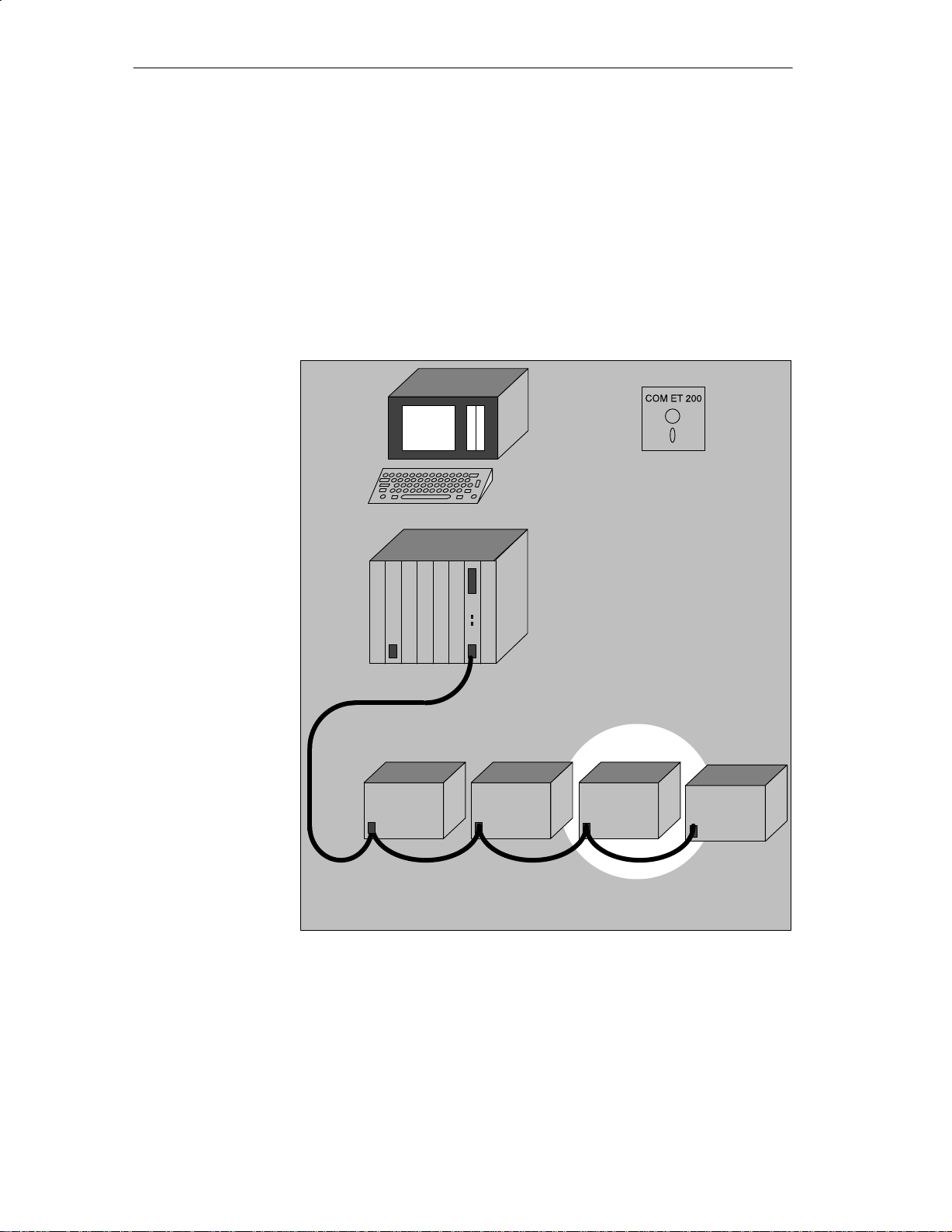
ET 200U is the designation for a slave station consisting of the following:
ET 200U interface module
Power supply
Bus units with up to 32 modules from the S5–100U I/O module spectrum.
The ET 200U distributed I/O station has the following characteristics:
IP 20 degree of protection
Accommodation of a maximum of 32 modules from the S5–100U module
spectrum (including CPs and IPs)
Maximum address space per ET 200U distributed I/O station
32 input bytes and 32 output bytes
Multi–tier configuration possible using the IM 315 and IM 316 interface
modules
Direct connection of a programmer or ET 200 Handheld for testing and
start–up (programmer with a CP 5410–S5DOS/ST programmer interface
module)
The station number of the ET 200U distributed I/O is switch–selectable
Example
The ET 200U module, Order No. 8MB11 is operated with DP Siemens
( Section 1.3)
The ET 200U module, Order No. 8MB12 can be operated either with DP
Siemens or with DP Standard ( Section 1.3)
ET 200U module, Order No. 8MC11 can be operated either with FMS or
with DP Standard ( Section 1.3)
High data throughput:
20 ET 200U distributed I/O stations with 8 input bytes and 8 output bytes
(= 2560 bits of user data) are connected to the bus. The baud rate set is
1500 Kbaud:
I.e., a complete data cycle lasts 5.9 ms. During the data cycle the IM 308–B
master interface module and the distributed I/Os exchange input/output data.
ET 200U Distributed I/O Station
EWA 4NEB 812 6087–02b
1-3

System Overview
1.3 What is DP Siemens and DP Standard?
What is DP Siemens and DP Standard?
Differences between DP Siemens
and DP Standard
What Does DIN
19245 Have to Offer?
DP Siemens is the bus protocol developed by Siemens. In cooperation with
the PROFIBUS User Organization, this bus protocol has been extended into
an open, multi–vendor system. This extended bus protocol has been filed
with the German Electrotechnical Commission (DKE) and it has been passed
as National draft standard DIN 19245, Part 3.
In this manual, the new bus protocol is called DP Standard.
The user interfaces of DP Siemens and DP Standard are very similar. All
functions which were available with an ET 200U(DP Siemens) are also provided for an ET 200U(DP Standard).
The DIN 19245 draft standard, Part 3, offers additional advantages:
Slave stations which meet the DIN 19245 draft standard, Part 3, can be
connected to the ET 200 distributed I/O system
Master stations which meet the DIN 19245 draft standard, Part 3, are able
to communicate with the ET 200U(DP Standard) slave station
The PROFIBUS DIN 19245 field bus standards cover a great variety of functions, thus making the bus system suitable for universal use, from the control
and cell level right up to the field level.
The ET 200 distributed I/O system is based on DIN 19245, Part 1 and supplements the definitions contained therein for the special applications in the
field of distributed I/O systems.
1-4
DIN 19245, Part 1 describes the bus access and line protocol as well as the
definitions for the required transmission hardware technique.
DIN 19245, Part 3 offers a solution for distributed I/O applications calling for
short system response times.
The major task of DIN 19245, Part 3, is the fast cyclic data exchange between the central PLCs (master station) and the I/O units (slave station).
DIN 19245, Part 3, offers the following features:
Transmission of 1024–bit I/O data for 32 stations in less than 10 ms.
Extensive diagnostics
Reduced parameterization and configuring effort
ET 200U Distributed I/O Station
EWA 4NEB 812 6087–02b

System Overview
What is FMS?
Definition
At Siemens, FMS is defined as the PROFIBUS DIN 19245 bus protocol,
Parts 1 and 2.
DIN 19245, Part 1, describes the bus access and transmission protocol and
the conventions for the transmission hardware required. DIN 19245, Part 2,
defines the application protocol and the user interface.
PROFIBUS–FMS has been developed especially for automation applications.
It enables automation systems of different manufacturers to communicate
with one another. PROFIBUS–FMS permits good connectivity to higher–
level automation systems.
The DP protocol offers faster response times than FMS so that FMS is intended rather for applications where time is not a crucial factor.
In this manual, the following three terms are used to distinguish the different
systems:
ET 200U: Slave station with IM 318–B interface module, in gene-
ral
ET 200U
(DP Siemens):
“318–8MB11”
or
“318–8MB12” which uses the “DP Siemens” bus protocol just like a “318–8MB11”.
ET 200U
(DP Standard):
“318–8MB12”
or
“318/8MC11” which uses the “DP Standard” bus protocol. DP Standard refers to the DIN 19245 draft standard,
Part 3.
ET 200U
(DP Standard/
FMS):
The “318–8MC11” uses both the “DP Standard” and
“FMS” bus protocols. The ET 200U (DP Standard/FMS)
can handle the sensor/actuator profile up to device
class 4.
ET 200U Distributed I/O Station
EWA 4NEB 812 6087–02b
1-5

Technical Description
2.1 Design of the ET 200U Interface Module 2-2. . . . . . . . . . . . . . . . . . . . . . . . . . . .
2.2 Technical Specifications 2-4. . . . . . . . . . . . . . . . . . . . . . . . . . . . . . . . . . . . . . . . . . .
Spectrum of I/O Modules 2-4. . . . . . . . . . . . . . . . . . . . . . . . . . . . . . . . . . . . . . . . . .
Figures
2-1 Design of the ET 200U Interface Module 2-3. . . . . . . . . . . . . . . . . . . . . . . . . . . .
2
ET 200U Distributed I/O Station
EWA 4NEB 812 6087-02b

Technical Description
The ET 200U distributed I/O station consists of the ET 200U interface module and the I/O modules.
This chapter contains a description of the controls and display elements of
the ET 200U interface module.
2
ET 200U Distributed I/O Station
EWA 4NEB 812 6087–02b
2-1

Technical Description
2.1 Design of the ET 200U Interface Module
“RUN” LED (green)
This LED lights up when the ET 200U interface module is in the
RUN mode (STOP/RUN switch in the “RUN” position and power
supply switched on)
“BUS–FAULT” LED (red)
“IM–FAULT” LED (red)
STOP/RUN switch
SINEC L2–DP interface
Terminals for 24 V supply and functional earth
Switch for setting the station number and
S the baud rate of the I/O bus (... 8MB11) ( Section 4.2.1)
or
S DP Siemens / DP Standard characteristics (... 8MB12)
( Section 5.2.1) or
S Switching from FMS to DP Standard bus parameters and vice
versa
(... 8MC11) ( Section 6.2).
Field for station number labels
Plug connector for connection of a bus unit
The LED indications are described in detail in the following Sections:
S ET 200U(DP Standard) in Section 4.3.1,
S ET 200U(DP Standard) in Section 5.3.1,
S ET 200U(DP Standard/FMS) in Section 6.4.
2-2
ET 200U Distributed I/O Station
EWA 4NEB 812 6087–02b

Technical Description
Figure 2-1 Design of the ET 200 Interface Module
ET 200U Distributed I/O Station
EWA 4NEB 812 6087–02b
2-3
 Loading...