

Siemens Simatic S5-101U Programming Instructions Manual
SIEMENS
Pr~gramma~ble Controller
Programming Instructions
Order No.: GWA 4NEB 810 2120-02 a
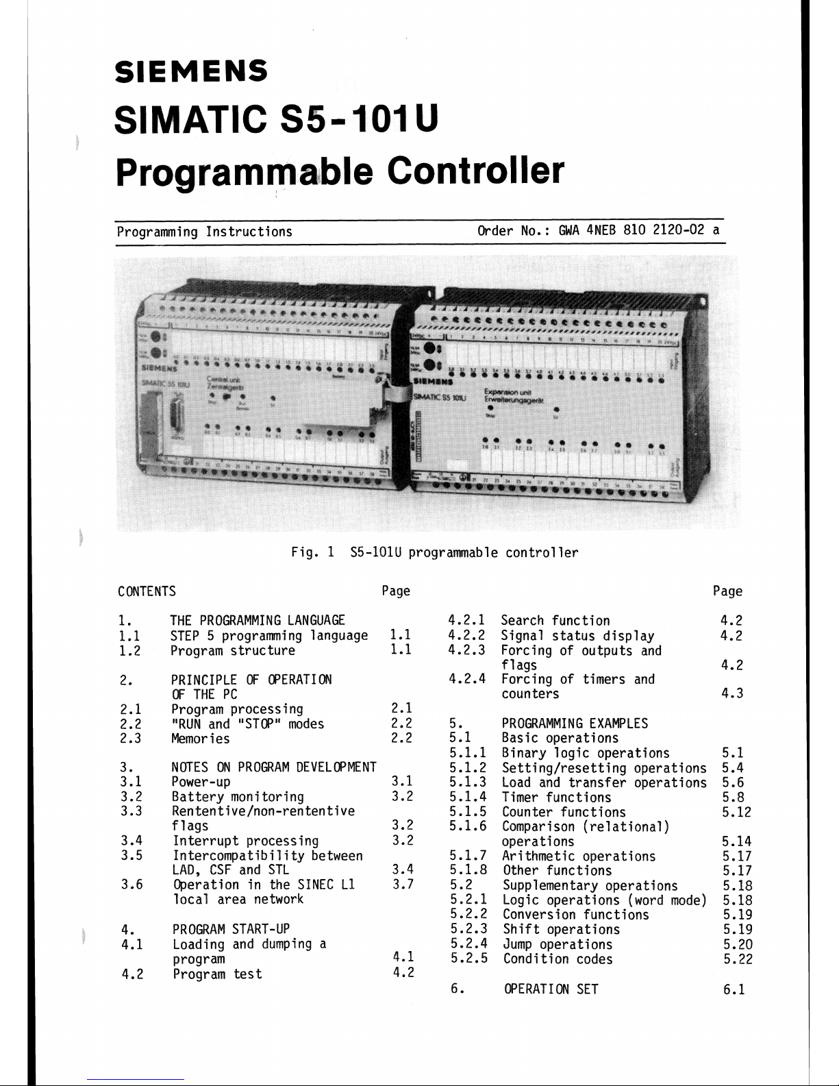
Fig.
1
S5-101U programmable controller
CONTENTS Page Page
THE PROGRAMMING LANGUAGE
4.2.1
STEP 5 programming language
1.1
4.2.2
Program structure
1.1
4.2.3
PRINCIPLE
OF
OPERATION 4.2.4
OF THE PC
Program processing 2.1
"RUN
and "STOP" modes 2.2 5.
Memor i es 2.2 5.1
5.1.1
NOTES
ON
PROGRAM
DEVELOPMENT 5.1.2
Power-up 3.1 5.1.3
Battery mon
i
tor i ng 3.2 5.1.4
Ren ten
tive/non-rententive 5.1.5
flags 3.2 5.1.6
Interrupt processing 3.2
Intercompatibi
l
i
ty between 5.1.7
LAD,
CSF and STL 3.4 5.1.8
Operation in the SINEC L1 3.7 5.2
local area network 5.2.1
5.2.2
PROGRAM START-UP 5.2.3
Loading and dumping a
5.2.4
program
4.1
5.2.5
Program test
4.2
6.
Search function
Signal status display
Forcing of outputs and
flags
Forcing of timers and
counters
PROGRAMMING EXAMPLES
Basic operations
Binary logic operations
Setting/resetting operations
Load and transfer operations
Timer functions
Counter functions
Comparison (relational)
operations
Arithmetic operations
Other functions
Supplementary operations
Logic operations (word mode)
Conversion functions
Shift operations
Jump operations
Cond
i
t
i
on codes
OPERATION SET
1.
The
programming language
1.1
STEP 5 programming language
The user programs are written in the
STEP 5 programning language. The
statements of this
l
anguage permit
not only the programning of simple
binary functions but also the programming of complex digital functions.
Depending on the programmer used, all
three methods of representation
statement list (STL)
1 adder d
i
agram (LAD)
control system flowchart (CSF)
are possible so that the method of
programming can be adapted to the
particular application. Only STL programming is possible with the handheld 605U programmer. The machine
code generated by the 6701675 pro-
grammers is identical for all
three methods of representat ion
..
1.2
Program structure
The user program consists of up to
1024
statements and can be written as a program block (PB) or function block (FB).
WFy
PBl
at
FBI
can
k
exwwted
on
%c
S5+1O1U
programable
contrallsr,
Program block
A program block can be programmed and
documented in
a11 three methods of re-
presentation (STL, LAD and CSF).
A
program block can be translated from one
method of representation into the two
other methods with the 6701675 programmers provided certain programming rules
are observed (see Section
3.4).
For users famil far with contactors and
re1 ays, the LAD method is recommended
since the ladder diagram has very close
similarities with schematic circuit
diagrams.
Program blocks are used especially
when a CRT-based
programmer is available and programming or documentation is to be made in graphic form.
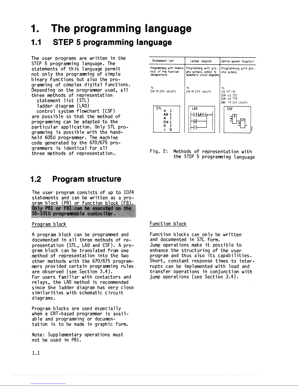
Fig.
2:
Methods of representation with
the STEP 5 programming language
to
3lN
19 239
idrcftl
Function block
Function blocks can only be written
and documented in STL form.
Jump operations make
it
possible to
enhance the structuring of the user
program and thus also its capabilities.
Short, constant response times to inter-
rupts can be implemented with load and
transfer operations in conjunction with
jump operations (see Section
3.4).
Note: Supplementary operations must
not be used in
PB1.
+o
2lh
19 239
Idrcctl
to
KC
117-15
DIN
L3
705
DIN
40
719
DIN
19
23i
,
lrrlfti
2.
Principle
of
operation
2.1
Program
processing
The control functions of the lOlU are
defined by a user program.
In order to be able to scan the user
program cyclically statement by state-
ment, the CPU
has to perform the follow-
ing functions:
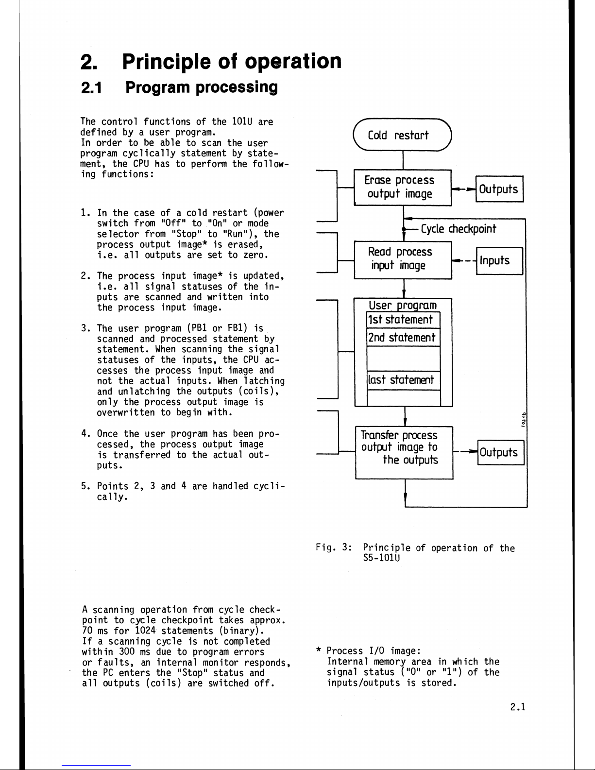
1.
In the case of a cold restart (power
switch from
"Off"
to "On" or mode
selector from "Stop" to "Run"), the
process output image* is erased,
i.e.
all outputs are set to zero.
2.
The process input image* is updated,
i.e. all signal statuses of the inputs are scanned and written into
the process input image.
The user program
(PB1 or FBI) is
scanned and processed statement by
statement. When scanning the signal
statuses of the inputs, the
CPU
accesses the process input image and
not the actual inputs. When latching
and unlatching the outputs (coils),
only the process output image is
overwritten to begin with.
4. Once the user program has been processed, the process output image
is transferred to the actual out-
puts.
5.
Points 2, 3 and 4 are handled cyclical
ly.
Cold restart
Cr>
Erase process
output image
I
Cycle checkpoint
Read
process
input image
12nd statement
I
Last statement
H
Transfer process
I
output image to
the outputs
Fig.
3:
Principle of operation of the
S5-101U
A
scanning operation from cycle checkpoint to cycle checkpoint takes approx.
70 ms for 1024 statements (binary).
If
a scanning cycle is not completed
within 300 ms due to program errors
*
Process 1/0 image:
or faults, an internal monitor responds,
Internal memory area in which the
the PC enters the "Stop" status and
signal
status
("0" or "1") of the
all outputs (coils) are switched off.
inputs/outputs is stored.
The
"Run"
and "Stop" modes
"RUN" mode
p-
In the "RUN" mode, the program is scanned
cyclically from cycle checkpoint to
cycle checkpoint. The PC is brought
into the "RUN" mode by
-
switching the mode selector to
"RUN1'
-
selecting the "PC RUN1' function of
the
programner (mode selector in "RUN"
position)
-
and on recovery of the power supply
if
the mode selector is at "RUN" and
was in the "RUN" position prior to
the power failure.
Memories
The PC has an internal program memory,
the data of which can be supported for
three years by a backup battery.
There are also two different memory
submodules (see Fig. 4).
"STOP" mode
In the "STOP" mode, the program is not
scanned and the outputs (coils) are
disabled. While the PC is in the "STOP"
state, all timers and counters and the
process 1/0 image retain the values
or states they had in the last scanning
cycle prior to the PC entering the "STOP"
state.
If
the PC is switched to "RUN",
the timers and counters (0
...
7) are
reset. The non-retentive flags and the
process 1/0 image are erased.
The
PC
is brought into the "STOP" mode
by
-
switching the mode selector to "STOP"
-
selecting the "PC STOP" function on
the programmer
-
faults or errors in program scanning,
e.g. time-out or operations that can
not be interpreted by the PC.
The cause for the PC entering the 'STOP"
state can be traced with the aid of
the "DISPLAY ESTACK" function of the
programner (see Section 4.2 of Operating
Instructions).
The memory submodules are used for pro-
gram dumping or for copying the program
should only one memory submodule be
used for a number of
PCs.
On
power-up or when the PC is switched
to
"RUN",
the contents of the memory
submodule are always copied into the
internal memory and processed there.
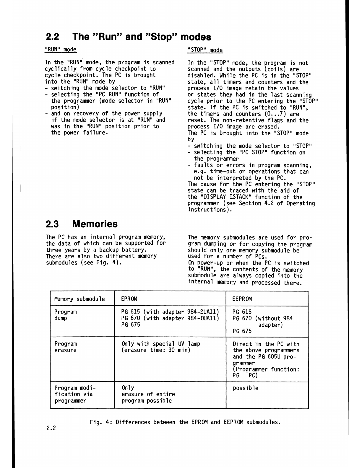
Fig. 4: Differences between the EPROM and EEPROM submodules.
Memory submodu
l
e
Program
dump
Program
erasure
Program mod
i
-
fication via
programmer
EPROM
PG
615 (with adapter 984-2UAll)
PG 670 (with adapter 984-OUAll)
PG 675
Only with special UV lamp
(erasure time: 30 min)
On
1~
erasure of entire
program possible
EEPROM
PG 615
PG 670 (without 984
adapter)
PG 675
Direct in the PC with
the above programmers
and the PG 605U
pro-
9
r
amme
r
Programmer function:
PG PC)
possible
3.
Notes on program development
Power
up
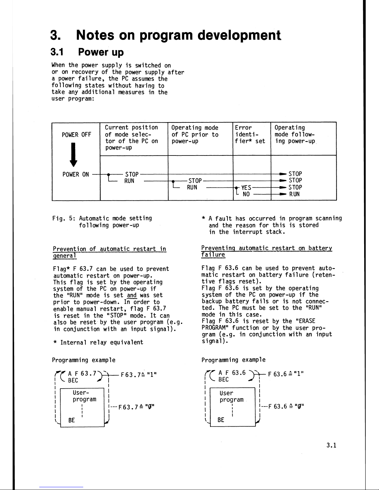
When the power supply is switched on
or on recovery of the power supply after
a power failure,
the PC assumes the
following states without having to
take any additional measures in the
user program:
Fig.
5:
Automatic mode setting
following power-up
Prevention of automatic restart in
general
Flag* F 63.7 can be used to prevent
automatic restart on power-up.
This flag is set by the operating
system of the PC on power-up
if
the
"RUN"
mode is set
and
was set
prior to power-down. In order to
enable manual restart, flag F 63.7
is reset in the "STOP" mode.
It
can
also be reset by the user program (e.g.
in conjunction with an input signal).
Error
i
dent
i
-
f
ier* set
-
YE
S
--------t
I
NO
Operating mode
of PC prior to
power-up
STOP
RUN
POWER OFF
l
POWER ON
*
Internal re1 ay equivalent
Operating
mode
follow-
i
ng power-up
-
STOP
STOP
S
TOP
-
RUN
Current position
of mode selector of the PC on
power-up
-
STOP
L
RUN
Programning example
)+
F63.7;
"1"
I
I
User-
!
I
I---
F 63
7
&
"9"
l
I
*
A
fault has occurred in program scanning
and the reason for this is stored
in the interrupt stack.
Preventinq automatic restart on battery
fail
ure
Flag F 63.6 can be used to prevent automatic restart on battery failure (retentive flags reset).
Flag F 63.6 is set by the operating
system of the PC on power-up
if
the
backup battery fails or is not connected. The PC must be set to the "RUN"
mode in this case.
Flag F 63.6 is reset by the "ERASE
PROGRAM" function or by the user pro-
gram (e.g. in conjunction with an input
signal).
Programming example
3.2
Battery
monitoring
Flag F 63.6 is used for monitoring the
The PC must be in the "RUN" state.
battery.
Flag F 63.6 is reset by the "ERASE PRO-
This flag is set by the operating system
GRAM"
function of the programner or by
of the PC on power recovery and during
the user program. The user can therefore
the normal scanning cycle
if
failure determine how the PC is to react to
of the battery backup
v01 tage
is detected.
backup battery fail ure.
The
S5-101W has a total of 512 flags.
The flag area is subdivided as follows:
Retentive flags (F
0.0
...
F
31.7)
-
retain their last state prior to
-
power-down on power-up (with backup
battery only)
-
retain their last state when the
mode is changed from "STOP" to "RUN"
(with and without backup battery)
-
are reset like the non-retentive
flags on power-up (without backup
battery)
-
can also be reset by the user program
(
"
ERASE PROGRAM" function
).
By using retentive flags, the last
status of the plant or machine prior
to the PC leaving the "RUN" mode can
be stored. On restart, the plant or
machine can resume operations at the
point at which
it
was stopped.
Interrupt processing
When an interrupt signal (e.g. emer-
gency off) from the process is re-
ceived by the PC, the latter interrupts cyclic scanning of the user program
and inititates the processing of a
specific interrupt routine.
Interrupt processing with the
S5-101U
is defined exclusively by the user program so that each input and output can
be used for interrupt processing.
Non-retentive flags (F 32.0.. .F 63.7)
-
are reset when the PC mode changes
from "STOP" to "RUN" and on power-up.
Flags F 61.0
-
F 62.7 are reserved
as coordinating
fl
ags for operation
in the SINEC L1 local area network;
flags F 63.0
-
F 63.7 are reserved
as system flags. Since they are affected by the PC operating system,
they must not be used as flags in
the normal sense.
In order to achieve minimum response
times, the inputs and outputs are referenced direct, i.e. outside cyclic
program scanning. The
load/transfer
operations "LPB" (inputs) and "TPB"
(outputs) are available for this purpose.
A
more or less constant response time
is achieved
if
the scanning of the in-
puts
programmed by the user as interrupt
inputs is uniformly distributed over
the entire user program. Fig. 6 shows
a user program with interrupt processing.
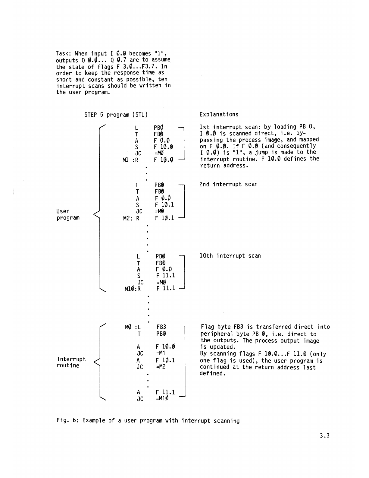
Task: When input
I
0.0
becomes
"l",
outputs
Q
@.g.
..
Q
0.7
are to assume
the state of flags F
3.a
...
F3.7. In
order to keep the response time as
short and constant as possible,
ten
interrupt scans should be written in
the user program.
User
program
STEP
5
program (STL)
Interrupt
routine
Expl
anat ions
1st interrupt scan: by loading PB
0,
I
0.0
is scanned direct, i.e. bypassing the process image, and mapped
on F
@.a.
If
F
0.0
(and consequently
I
0.0)
is
"l",
a jump is made to the
interrupt routine.
F
10.0
defines the
return address.
2nd
i
nterrupt scan
10th interrupt scan
Flag byte FB3 is transferred direct into
peripheral byte PB
0,
i.e. direct to
the outputs. The process output image
is updated.
By scanning flags
F
10.0
...
F 11.0 (only
one flag is used), the user program is
continued at the return address last
defined.
Fig.
6:
Example of a user program with interrupt scanning
3.5
Intercompatibility between LAD, CSF and STL
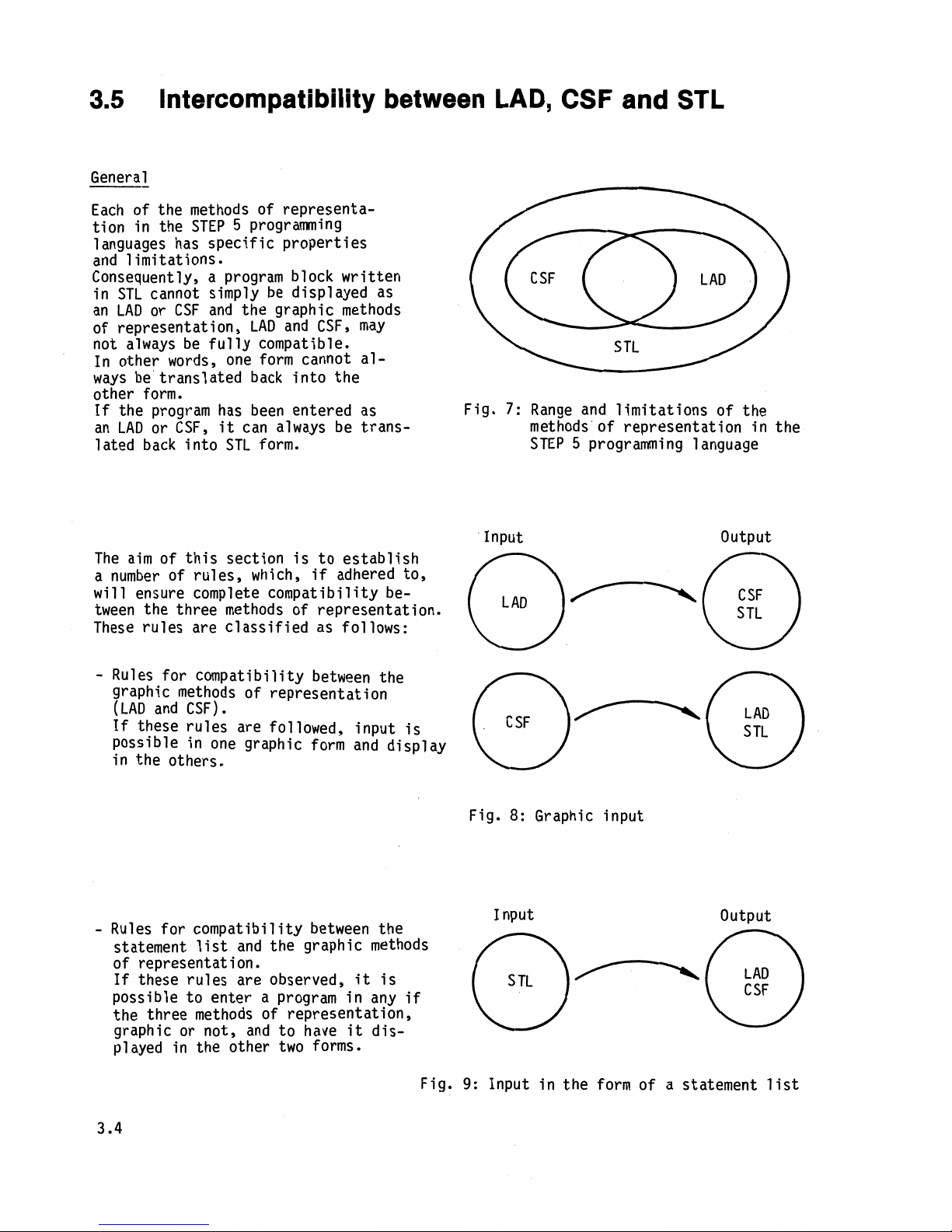
General
Each of the methods of representation in the STEP
5
programming
languages has specific properties
and limitations.
Consequently, a program block written
in STL cannot simply be displayed as
an LAD or CSF and the graphic methods
of representation, LAD and
CSFy may
not always be fully compatible.
In other words, one form cannot always be translated back into the
other form.
If
the program has been entered as
Fig.
7:
Range and limitations of the
an LAD or CSF,
it
can always be trans- methods of representation in the
lated back into STL form. STEP
5
programming language
Input Output
The aim of this section is to establish
a number of rules, which,
if
adhered to,
will
ensure complete compatibility be-
tween the three methods of representation.
These rules are classified as follows:
-
Rules for compatibility between the
graphic methods of representation
(LAD and CSF)
.
If
these rules are followed, input is
possible in one graphic form and display
in the others.
Fig.
8:
Graphic input
I
nput Output
-
Rules for compatibility between the
statement list and the graphic methods
of representat ion.
If
these rules are observed,
it
is
possible to enter a program in any
if
the three methods of representation,
graphic or not, and to have
it
dis-
played in the other two forms.
Fig.
9:
Input
in the form of
a statement list
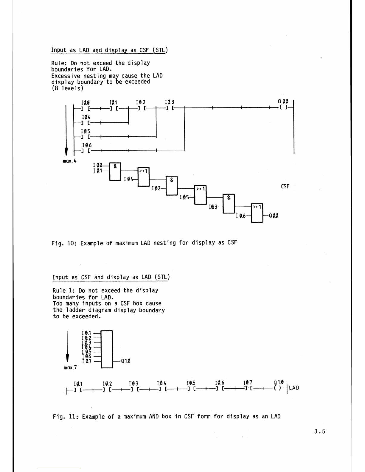
Input as LAD and dis~lav as CSF (STL)
Rule: Do not exceed the display
boundaries for LAD.
Excessive nesting may cause the LAD
display boundary to be exceeded
(8
levels)
max
.4
Example of maximum LAD nesting for display as CSF
Input as CSF and display as LAD
(STL)
Rule
1:
Do not exceed the display
boundaries for LAD.
Too many inputs on a CSF box cause
the
l
adder diagram display boundary
to be exceeded.
CSF
Fig.
11:
Example of a maximum
AND
box in CSF form for display as an LAD
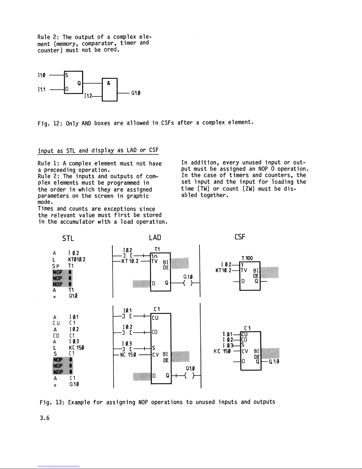
Rule 2: The output of a complex ele-
ment (memory, comparator, timer and
counter) must not be
ored.
Fig. 12: Only AND boxes are allowed in.CSFs after a complex element.
In~ut as STL and display as LAD or CSF
Rule
1:
A
complex element must not have
In addition, every unused input or
out-
a preceed i ng operation.
put must be assigned an NOP
0 operation.
Rule 2: The inputs and outputs of
com-
In the case of timers and counters, the
plex elements must be programmed in
set input and the input for loading the
the order in which they are assigned
time (TW) or count (ZW) must be
dis-
parameters on the screen in graphic
abled together.
mode.
Times and counts are exceptions since
the relevant value must first be stored
in the accumulator with a load operation.
STL
LAD
CSF
Fig. 13:
Example for assigning NOP operations to unused inputs and outputs
3.6
Operation in the SINEC
L1
local area network
The SINEC L1 local area network is used
for interconnecting
programnabl e con-
trol
l
ers of the l ow-end performance
range and operates on the Master-Slave
principle.
The CP 530
comrnun i cations processor
is always the Master, and the slaves
the
CPUs of all small PCs. Each slave
is assigned a
s1 ave number under which
it
is referenced. Data can be inter-
changed between the master and up to
30 slaves, as well as between the individual slaves. In the case of the
S5-101U,
the slave number, the coordinating flags
and the send and receive mailboxes are
defined as follows:
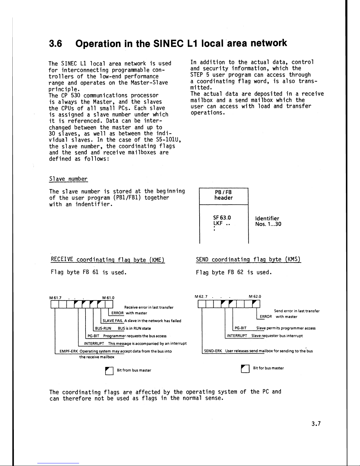
Slave
numk
The slave number is stored at the beginning
of the user program
(PBlIFB1) together
with an indentifier.
In addition to the actual data, control
and security information, which the
STEP 5 user program can access through
a coordinating flag word, is also trans-
mi
tted
.
The actual data are deposited in a receive
mailbox and a send mailbox which the
user can access with load and transfer
operations.
header
SF
63.0
LKF
..
Identifier
Nos.
1...30
RECEIVE coordinatinq
fl
aq b.yte (KME)
SEND coordinating
fl
aq byte (KMS)
Flag byte FB
61
is used. Flag byte FB
62
is used.
M61.7
.
.
.
M 61.0
I
I
1-r~
Receive error in last transfer
ERROR with master
SLAVE
FAIL A slave in the network has failed
BUS-RUN BUS is in RUN state
PG-BIT Programmer requests the bus access
INTERRUPT This message is accompanied by an interrupt
EMPF-ERK Operating system may accept data from the bus into
the receive
mailbox
Bit from bus master
M62.7
.
M
62.0
Send error In last transfer
Slave permits programmer access
SEND-ERK User releases send
mailbox for sending to the bus
Bit for bus master
The coordinating flags are affected by the operating system of the PC and
can therefore not be used as flags in the normal sense.
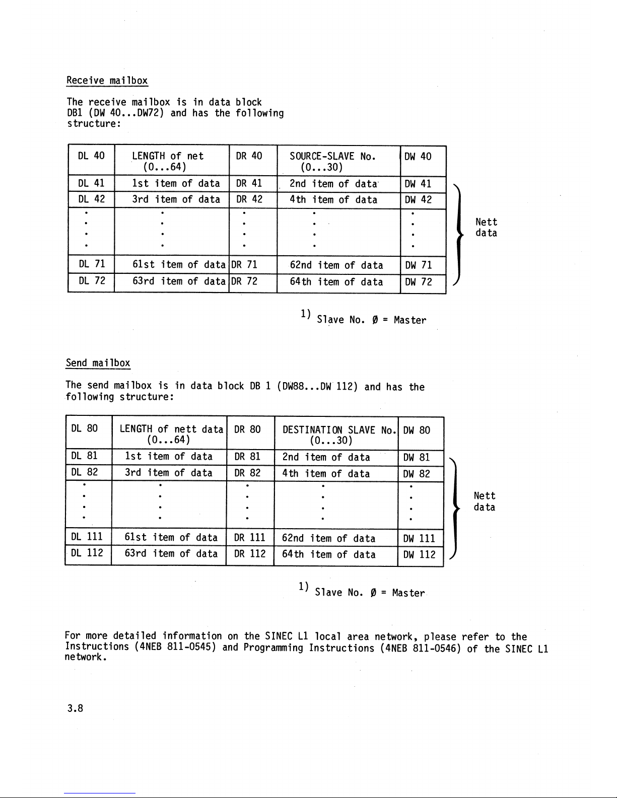
Receive mailbox
The receive mailbox is in data block
DB1 (DW 40
...
DW72) and has the following
structure
:
l) Slave No.
0
=
Master
DL 40
DL 41
DL 42
DL 71
DL 72
Send
mailbox
The send mailbox is in data block DB 1 (DW88..
.DW
112) and has the
following structure:
LENGTH of net
(0..
.64)
1st i tern of data
3rd item of data
61st item of data
63rd item of data
l) Slave No.
0
=
Master
DR 40
DR
41
DR
42
DR 71
DR
72
DL 80
DL 81
DL 82
DL
111
Nett
data
Nett
data
SOURCE-SLAVE No.
(0..
.30)
2nd item of data
4th item of data
62nd
i
tem of data
64th
itemof data
LENGTH of nett data
(0..
.64)
1st item of data
3rd item of data
61st item of data
For more detailed information on the SINEC L1 local area network, please refer to the
Instructions
(4NEB 811-0545) and Programming Instructions (4NEB 811-0546) of the SINEC L1
network
.
DW 40
DW 41
DW 42
DW 71
DW 72
DL 112 63rd item of data
DR
112
DR
80
DR
81
DR 82
DR
111
p
p-
64th item of data DW 112
DESTINATION SLAVE No.
(0..
.30)
2nd item of data
4th
i
tern of data
62nd item of data
.-
DW 80
DW 81
DW 82
DW
111
4.
Program Start
=up
The hand-held PG 605U/615 programmer
The following settings are necessary
and the CRT-based PG 670 and PG 675
on the PG 670 and PG 675 programners
programmers can be used for loading
in conjunction with the
S5-1101 U pro-
and testing programs. grammable controller:
PG 670:
S5-150
AK
S5-130
W
PG 675: S5-150
S
NO
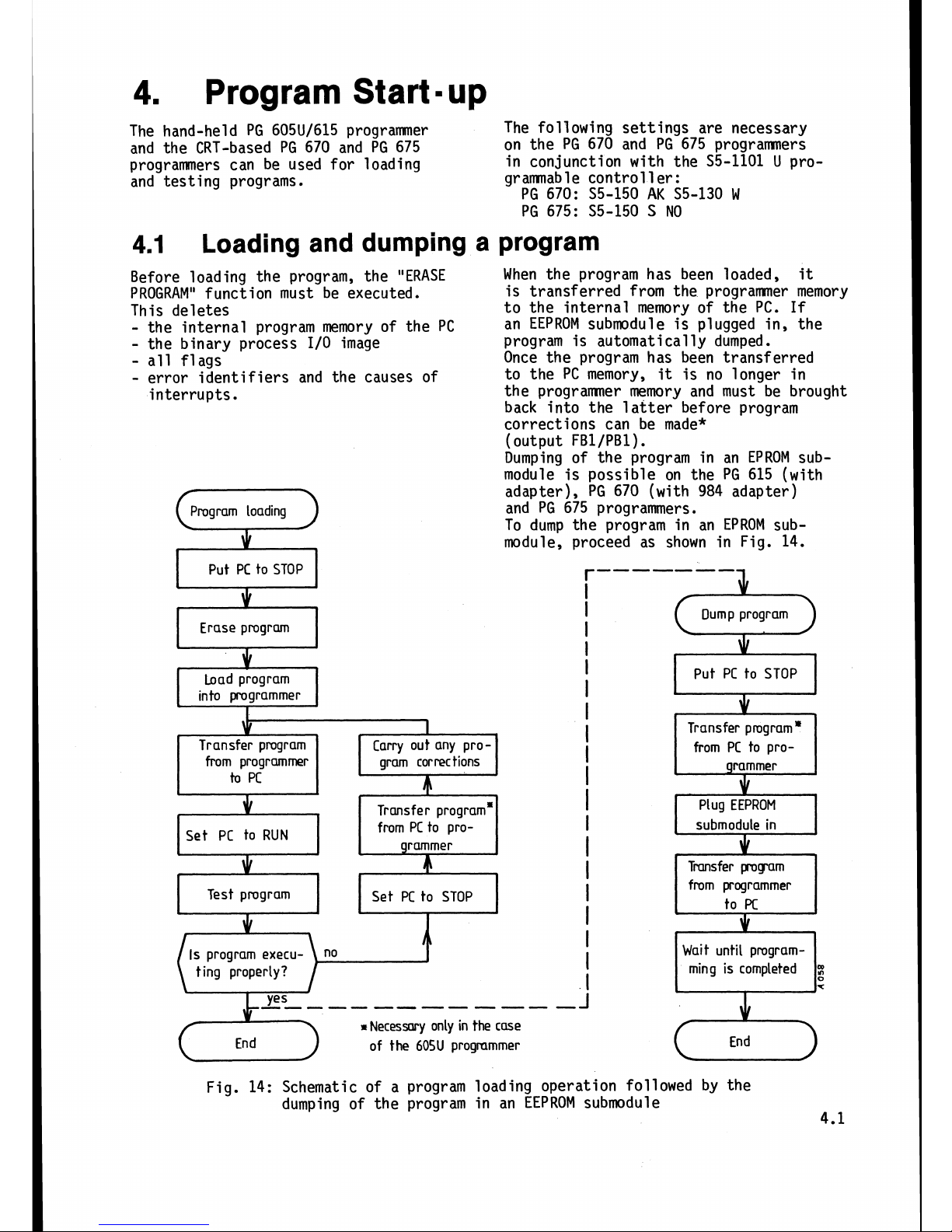
4.1
Loading and dumping a program
Fig. 14: Schematic of a program loading operation followed by the
dumping of the program in an EEPROM submodule
4.1
Before loading the program, the "ERASE
When the program has been loaded,
it
PROGRAM"
function must be executed.
is transferred from the
programmer memory
This deletes to the internal memory of the
PC.
If
-
the internal program memory of the PC
an EEPROM submodule is plugged in, the
-
the binary process
I/O
image
program is automatically dumped.
-
all flags
Once the program has been transferred
-
error identifiers and the causes of
to the PC memory,
it
is no longer in
interrupts.
the programner memory and must be brought
back into the latter before program
corrections can be made*
(output
FBl/PBl)
.
Dumping of the program in an EPROM sub-
module is possible on the PG 615 (with
adapter), PG 670 (with 984 adapter)
and PG 675 programmers.
To dump the program
in
an EPROM sub-
module, proceed as shown in Fig. 14.
Put PC to STOP
r-------
*
I
I
Dump program
Erase program
I
t
I
\Ir
Load program
I
Put PC to STOP
into
programmer
1
i
I
$
I
Transfer pmgram
Carry out any
pro-
I
from programmer gram corrections
Transfer program'
from
PC
to pro-
*
4
I
grammer
to
PC
JI
JI
-
Transfer program'
I
Plug EEPROM
from PC to pro-
I
submodule
in
Set
PC
to RUN
grammer
L
*
JI
4
I
r
I
Tmnsfer pmg-am
I
from programmer
Test pmgram
Set
PC
to STOP
+
JI
I
to
Pc
'b
2
T
I
\
.
I
.
r
Is program execu-
I
4
I
t
ing properly?
I
J
R
Necessary only in the case
of the
605U
progmmmer End
Wait until program-
ming is completed
 Loading...