

Siemens Simatic RTU303xC Series, Simatic RTU3030C, Simatic RTU3031C Operating Instructions Manual

SIMATIC
TeleControl - RTU
RTU303xC
Operating Instructions
RTU3030C
RTU3031C
06/2019
C79000
Preface
Application and functions
1
LEDs, connectors, buttons,
card slots
2
Connecting up, installation,
commissioning
3
Configuration (WBM)
4
Program blocks
5
Diagnostics and
maintenance
6
Technical data
7
Approvals
A
Dimension drawings
B
Accessories
C
Syslog Messages
D
Documentation references
E
RTU303xC
-G8976-C382-06
Siemens AG
Division Process Industries and Drives
Postfach 48 48
90026 NÜRNBERG
GERMANY
C79000-G8976-C382-06
Ⓟ
Copyright © Siemens AG 2015 - 2019.
All rights reserved
DANGER
indicates that death or severe personal injury will result if proper precautions are not taken.
WARNING
indicates that death or severe personal injury may result if proper precautions are not taken.
CAUTION
indicates that minor personal injury can result if proper precautions are not taken.
NOTICE
indicates that property damage can result if proper precautions are not taken.
WARNING
Siemens products may only be used for the applications described in the catalog and in the relevant technical
ambient conditions must be complied with. The information in the relevant documentation must be observed.
Legal information
Warning notice system
This manual contains notices you have to observe in order to ensure your personal safety, as well as to prevent
damage to property. The notices referring to your personal safety are highlighted in the manual by a safety alert
symbol, notices referring only to property damage have no safety alert symbol. These notices shown below are
graded according to the degree of danger.
If more than one degree of danger is present, the warning notice representing the highest degree of danger will
be used. A notice warning of injury to persons with a safety alert symbol may also include a warning relating to
property damage.
Qualified Personnel
The product/system described in this documentation may be operated only by personnel qualified for the specific
task in accordance with the relevant documentation, in particular its warning notices and safety instructions.
Qualified personnel are those who, based on their training and experience, are capable of identifying risks and
avoiding potential hazards when working with these products/systems.
Proper use of Siemens products
Note the following:
documentation. If products and components from other manufacturers are used, these must be recommended
or approved by Siemens. Proper transport, storage, installation, assembly, commissioning, operation and
maintenance are required to ensure that the products operate safely and without any problems. The permissible
Trademarks
All names identified by ® are registered trademarks of Siemens AG. The remaining trademarks in this publication
may be trademarks whose use by third parties for their own purposes could violate the rights of the owner.
Disclaimer of Liability
We have reviewed the contents of this publication to ensure consistency with the hardware and software
described. Since variance cannot be precluded entirely, we cannot guarantee full consistency. However, the
information in this publication is reviewed regularly and any necessary corrections are included in subsequent
editions.
05/2019 Subject to change
Preface
CAUTION
To prevent injury, read the manual before use.
Validity of this manual
This manual is valid for the products:
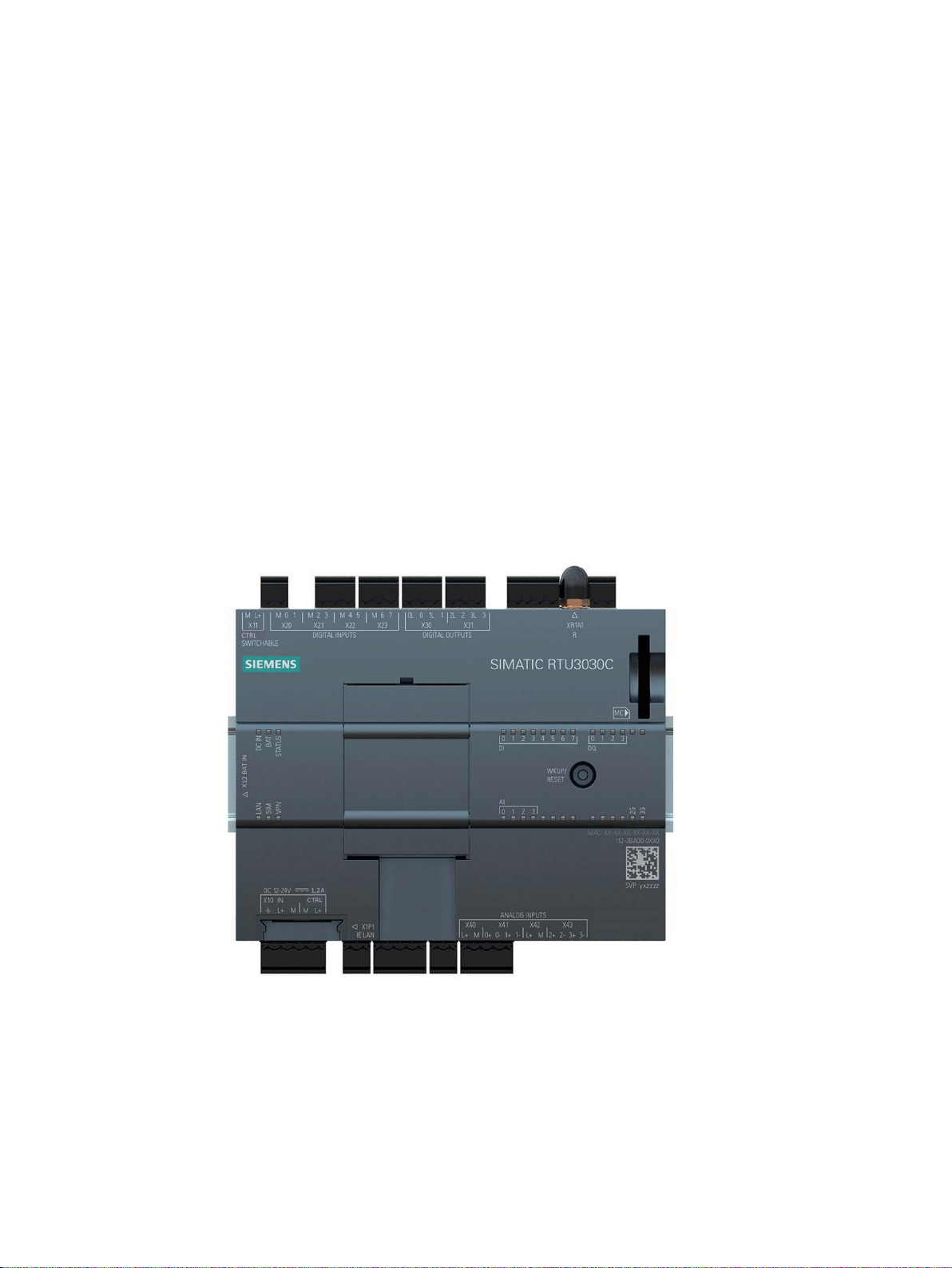
SIMATIC RTU3030C
Article number: 6NH3112-3BA00-0XX0
Hardware product version 2
Firmware version 3.1
The RTU is used to monitor and control outlying stations that are geographically distributed
and not connected to a power supply network. The RTU can store process data and transfer
it via mobile wireless or via the LAN interface and an external router to a master station.
RTU303xC
Operating Instructions, 06/2019, C79000-G8976-C382-06
Figure 1 SIMATIC RTU3030C
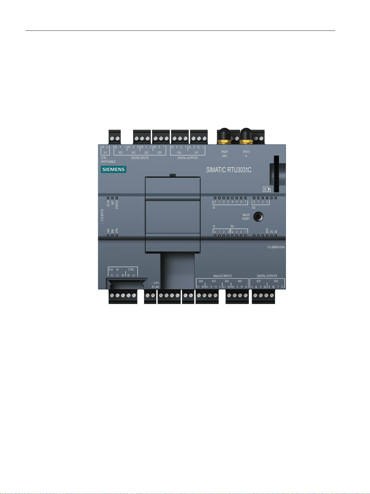
SIMATIC RTU3031C
Article number: 6NH3112-3BB00-0XX0
Hardware product version 2
Firmware version 3.1
3
Preface
The RTU is used to monitor and control outlying stations that are geographically distributed
and not connected to a power supply network. The RTU can store process data and transfer
it via mobile wireless or via the LAN interface and an external router to a master station.
The RTU3031C also has 4 additional digital outputs and supports GPS positioning and time
synchronization.
Figure 2 SIMATIC RTU3031C
You will find the the article number of the device on the front right of the housing
You will find the hardware product version of the device as a placeholder "X" printed on the
right side of the housing. Hardware version 2 is designated by "1 X 3 4"
You will find the the MAC address of the device on the front right of the housing
You will find the IMEI (International Mobile Equipment Identity) on the right had-side of the
housing.
Purpose of the manual
This manual describes the properties of this device and shows application examples.
RTU303xC
4 Operating Instructions, 06/2019, C79000-G8976-C382-06

Preface
The manaul supports you when installing, connecting up and commissioning the device.
The required configuration steps for the device are described.
You will also find instructions for operation and information about the diagnostics options.
Required experience
To install, commission and operate the device, you require experience in the following areas:
● General electrical engineering
● Automation engineering
● Data transfer via mobile wireless networks and Internet
Abbreviations/acronyms
This manual often uses the following abbreviations/acronyms:
●
RTU
The name "RTU" (Remote Terminal Unit) is used instead of the full product names
"RTU3010C", "RTU3030C" and "RTU3031C".
●
RTU30x0C
Used as a substitute for the complete product names of the "RTU3010C" and
"RTU3030C" devices.
●
RTU303xC
Used as a substitute for the complete product names of the "RTU3030C" and
"RTU3031C" devices.
●
HW2
Stands for devices with hardware product version 2.
●
WBM
"WBM" the acronym for the "Web Based Management" of the Web pages of the RTU for
configuration and diagnostics data.
●
Extension board
The term "extension board" is used instead of the full product name "EXTENSION
BOARD HART / RS485".
●
TCSB
Acronym for the control center software "TeleControl Server Basic" which is installed on a
PC, the telecontrol server.
New in this release
● Connection from up to 8 Hart devices through the expansion card "EXTENSION BOARD
HART / RS485"
● Remote access for SIMATIC PDM to HART and Modbus devices via HART-IP or Modbus
TCP
RTU303xC
Operating Instructions, 06/2019, C79000-G8976-C382-06
5

Preface
Note
Open source software
Read the license conditions for open source software carefully before using the product.
● Central logging of security and audit events; sending of events via the Syslog protocol.
● DNP3 redundancy
● Revision of function block "Silo volume calculation"
● Increase in configuration limits for function blocks
● Editorial revision
For the product notices on the Internet see:
Link: (https://support.industry.siemens.com/cs/ww/en/ps/21767/pm)
Replaced edition
Edition 07/2018
Current manual release on the Internet
You will also find the current version of this manual on the Internet pages of Siemens
Industry Online Support:
Link: (https://support.industry.siemens.com/cs/ww/en/ps/21767/man)
Cross references
In this manual there are often cross references to other sections.
To be able to return to the initial page after jumping to a cross reference, some PDF readers
support the command <Alt>+<left arrow>.
Sources of information and other documentation
You will find an overview of further reading and references in the Appendix of this manual.
License conditions
You will find the license conditions as a loadable file on the WBM pages of the device. You
will find the description of opening and loading license conditions in section General
functions of the WBM (Page 94).
You will find the packed file with the license conditions for Open Source software under the
following name:
● OSS_RTU30xxC_86.zip
RTU303xC
6 Operating Instructions, 06/2019, C79000-G8976-C382-06

Preface
Firmware
The firmware is signed and encrypted. This ensures that only firmware created by Siemens
can be downloaded to the device.
Security information
Siemens provides products and solutions with industrial security functions that support the
secure operation of plants, systems, machines and networks.
In order to protect plants, systems, machines and networks against cyber threats, it is
necessary to implement – and continuously maintain – a holistic, state-of-the-art industrial
security concept. Siemens’ products and solutions constitute one element of such a concept.
Customers are responsible for preventing unauthorized access to their plants, systems,
machines and networks. Such systems, machines and components should only be
connected to an enterprise network or the internet if and to the extent such a connection is
necessary and only when appropriate security measures (e.g. firewalls and/or network
segmentation) are in place.
For additional information on industrial security measures that may be implemented, please
visit
Link: (http://www.siemens.com/industrialsecurity)
Siemens’ products and solutions undergo continuous development to make them more
secure. Siemens strongly recommends that product updates are applied as soon as they are
available and that the latest product versions are used. Use of product versions that are no
longer supported, and failure to apply the latest updates may increase customers’ exposure
to cyber threats.
To stay informed about product updates, subscribe to the Siemens Industrial Security RSS
Feed under
Link: (http://www.siemens.com/industrialsecurity)
Recycling and disposal
The product is low in pollutants, can be recycled and meets the requirements of the WEEE
directive 2012/19/EU "Waste Electrical and Electronic Equipment".
Do not dispose of the product at public disposal sites. For environmentally friendly recycling
and the disposal of your old device contact a certified disposal company for electronic scrap
or your Siemens contact.
Keep to the local regulations.
You will find information on returning the product on the Internet pages of Siemens Industry
Online Support:
Link: (https://support.industry.siemens.com/cs/ww/en/view/109479891)
SIMATIC NET glossary
Explanations of many of the specialist terms used in this documentation can be found in the
SIMATIC NET glossary.
You will find the SIMATIC NET glossary on the Internet at the following address:
RTU303xC
Operating Instructions, 06/2019, C79000-G8976-C382-06
7

Preface
Link: (https://support.industry.siemens.com/cs/ww/en/view/50305045)
Training, Service & Support
You will find information on training, service and support in the multilanguage document
"DC_support_99.pdf" on the Internet pages of Siemens Industry Online Support:
Link: (https://support.industry.siemens.com/cs/ww/en/view/38652101)
RTU303xC
8 Operating Instructions, 06/2019, C79000-G8976-C382-06

Table of contents
Preface ................................................................................................................................................... 3
1 Application and functions ...................................................................................................................... 15
1.1 Application and use of the RTU .............................................................................................. 15
1.2 Configuration examples .......................................................................................................... 17
1.3 Modes and operating modes .................................................................................................. 21
1.4 Process connection - inputs / outputs ..................................................................................... 24
1.5 Control functions ..................................................................................................................... 24
1.6 Communications services ....................................................................................................... 25
1.7 Security functions for communication ..................................................................................... 32
1.8 Other services and properties ................................................................................................. 34
1.9 Performance data ................................................................................................................... 36
1.10 Scope of delivery, accessories, requirements ........................................................................ 39
2 LEDs, connectors, buttons, card slots ................................................................................................... 45
2.1 Appearance of the device ....................................................................................................... 45
2.2 LEDs ....................................................................................................................................... 46
2.3 Interfaces and connectors ...................................................................................................... 51
2.4 The button "WKUP/RESET" ................................................................................................... 57
2.5 Slots for SIM card and SD card .............................................................................................. 58
3 Connecting up, installation, commissioning ........................................................................................... 61
3.1 Important notes on using the device ....................................................................................... 61
3.1.1 Notices on use in hazardous areas ........................................................................................ 61
3.1.2 Notices on use in hazardous areas according to ATEX / IECEx ............................................ 63
3.1.3 Instructions for use in hazardous areas according to FM and UL HazLoc ............................. 64
3.1.4 Safety when connecting (devices without NEC Class 2) ........................................................ 65
3.1.5 Device defective ...................................................................................................................... 67
3.2 Requirements for commissioning ........................................................................................... 67
3.3 SD card / using and formatting SMC ...................................................................................... 68
3.4 Inserting the SIM card and SD card ........................................................................................ 69
3.5 Installing an RTU .................................................................................................................... 70
3.6 Grounding and overvoltage protection .................................................................................... 73
3.7 Connecting up the RTU .......................................................................................................... 74
3.8 Connecting devices to the extension board ............................................................................ 80
3.8.1 Modbus devices ...................................................................................................................... 80
RTU303xC
Operating Instructions, 06/2019, C79000-G8976-C382-06
9

Table of contents
3.8.2 HART devices ........................................................................................................................ 81
3.9 Commissioning and starting up the RTU ............................................................................... 84
4 Configuration (WBM) ............................................................................................................................ 89
4.1 Security recommendations .................................................................................................... 89
4.2 Range of functions of the WBM ............................................................................................. 92
4.3 General functions of the WBM ............................................................................................... 94
4.4 Permitted characters and parameter lengths ......................................................................... 95
4.5 Permissible file size for certificates and keys ...................................................................... 100
4.6 Establishing the connection between RTU and configuration PC ....................................... 100
4.6.1 Address data of the RTU ..................................................................................................... 100
4.6.2 Establishing a connection to the WBM of the RTU .............................................................. 101
4.7 User data for the first login to the WBM ............................................................................... 106
4.8 Logging in ............................................................................................................................. 107
4.9 Start page ............................................................................................................................. 108
4.9.1 Overview .............................................................................................................................. 108
4.9.2 Status ................................................................................................................................... 110
4.10 System ................................................................................................................................. 112
4.10.1 General ................................................................................................................................ 112
4.10.2 Device info ........................................................................................................................... 113
4.10.3 SD card ................................................................................................................................ 113
4.10.4 System time ......................................................................................................................... 116
4.11 Diagnostics ........................................................................................................................... 120
4.11.1 Diagnostics buffer ................................................................................................................ 120
4.11.2 Configuration ........................................................................................................................ 121
4.12 Maintenance ......................................................................................................................... 122
4.12.1 Configuration ........................................................................................................................ 122
4.12.2 Firmware .............................................................................................................................. 124
4.12.3 Operating status ................................................................................................................... 127
4.12.4 Online support ...................................................................................................................... 129
4.13 LAN ...................................................................................................................................... 130
4.13.1 Overview .............................................................................................................................. 130
4.13.2 Configuration ........................................................................................................................ 131
4.14 WAN ..................................................................................................................................... 133
4.14.1 Overview .............................................................................................................................. 133
4.14.2 Mobile wireless settings ....................................................................................................... 135
4.14.3 Wireless cell ......................................................................................................................... 140
4.14.4 SMS ..................................................................................................................................... 141
4.14.5 DynDNS ............................................................................................................................... 142
4.15 Services ............................................................................................................................... 144
4.15.1 Overview
.............................................................................................................................. 144
4.15.2 E-mail ................................................................................................................................... 145
4.15.3 FTP ...................................................................................................................................... 148
4.16 Security ................................................................................................................................ 150
RTU303xC
10 Operating Instructions, 06/2019, C79000-G8976-C382-06

Table of contents
4.16.1 Overview ............................................................................................................................... 150
4.16.2 VPN ....................................................................................................................................... 151
4.16.3 HTTPS .................................................................................................................................. 156
4.16.4 Event buffer ........................................................................................................................... 159
4.16.5 Syslog ................................................................................................................................... 160
4.17 Users / groups ....................................................................................................................... 161
4.17.1 User....................................................................................................................................... 161
4.17.2 Recipient groups ................................................................................................................... 164
4.18 Operating mode .................................................................................................................... 166
4.18.1 Operating modes .................................................................................................................. 166
4.18.2 Logging ................................................................................................................................. 169
4.18.3 Power supply ........................................................................................................................ 171
4.18.4 Battery service life ................................................................................................................. 176
4.18.5 Batteries: Estimating the working life .................................................................................... 176
4.19 Tags ...................................................................................................................................... 178
4.19.1 Overview ............................................................................................................................... 178
4.19.2 Configuration of the tags , general parameters .................................................................... 179
4.19.3 Digital inputs ......................................................................................................................... 181
4.19.4 Digital outputs / Digital memory bits ..................................................................................... 184
4.19.5 Analog inputs ........................................................................................................................ 184
4.19.6 Analog memory bits .............................................................................................................. 193
4.19.7 Temperature (Internal) .......................................................................................................... 194
4.19.8 Power supply (external) ........................................................................................................ 195
4.19.9 Battery ................................................................................................................................... 195
4.19.10 Texts ..................................................................................................................................... 196
4.20 Extension board .................................................................................................................... 199
4.20.1 General ................................................................................................................................. 199
4.20.2 RS-485 Modbus .................................................................................................................... 201
4.20.3 HART .................................................................................................................................... 203
4.20.4 Devices ................................................................................................................................. 205
4.20.5 Tags ...................................................................................................................................... 206
4.21 GPS (RTU3031C) ................................................................................................................. 211
4.21.1 General ................................................................................................................................. 211
4.21.2 Tags ................................
...................................................................................................... 212
4.22 Program ................................................................................................................................ 213
4.22.1 Creating the user program using program blocks ................................................................ 213
4.23 Telecontrol ............................................................................................................................ 213
4.23.1 Overview ............................................................................................................................... 213
4.23.2 TeleControl Basic .................................................................................................................. 215
4.23.3 ST7........................................................................................................................................ 218
4.23.4 DNP3..................................................................................................................................... 220
4.23.5 IEC 60870-5-104 ................................................................................................................... 226
4.23.6 Data points ............................................................................................................................ 230
4.23.7 Status IDs of the data points ................................................................................................. 239
4.23.8 Wake-up call / wake-up SMS ................................................................................................ 240
4.24 Tag tables ............................................................................................................................. 243
4.24.1 Overview ............................................................................................................................... 243
RTU303xC
Operating Instructions, 06/2019, C79000-G8976-C382-06
11

Table of contents
5 Program blocks .................................................................................................................................... 249
5.1 Block overview ..................................................................................................................... 249
5.2 Parameter assignment of the blocks.................................................................................... 251
5.3 Often used parameters ........................................................................................................ 252
5.4 Blocks for logical functions ................................................................................................... 255
5.4.1 Logical AND ......................................................................................................................... 255
5.4.2 Logical OR ........................................................................................................................... 256
5.4.3 Exclusive OR (XOR) ............................................................................................................ 257
5.4.4 Logical NOT ......................................................................................................................... 258
5.5 Blocks for basic types of calculation .................................................................................... 259
5.5.1 Addition ................................................................................................................................ 259
5.5.2 Subtraction ........................................................................................................................... 259
5.5.3 Multiplication ........................................................................................................................ 260
5.5.4 Division ................................................................................................................................. 261
5.6 Blocks for time functions ...................................................................................................... 262
5.6.1 On delay ............................................................................................................................... 262
5.6.2 Off delay ............................................................................................................................... 263
5.6.3 On / Off delay ....................................................................................................................... 265
5.6.4 Retentive on delay ............................................................................................................... 266
5.6.5 Pulse generator .................................................................................................................... 268
5.6.6 Random on/off delay ............................................................................................................ 268
5.6.7 Pulse sequence.................................................................................................................... 269
5.6.8 Year timer ............................................................................................................................. 273
5.6.9 Week timer ........................................................................................................................... 276
5.6.10 Astronomical clock ............................................................................................................... 277
5.7 Blocks for analog value functions ........................................................................................ 279
5.7.1 Triggered saving .................................................................................................................. 279
5.7.2 Analog value monitoring ...................................................................................................... 280
5.7.3 Limit value switch ................................................................................................................. 281
5.7.4 Difference limit switch .......................................................................................................... 284
5.7.5 Range monitoring ................................................................................................................. 287
5.7.6 Analog value comparator ..................................................................................................... 289
5.7.7 Min. /Max. /Mean value ........................................................................................................ 290
5.7.8 Analog value processing ...................................................................................................... 292
5.7.9 GPS position (RTU3031C) ................................................................................................... 293
5.7.10 Statistics ............................................................................................................................... 295
5.8 Counter and summation blocks ........................................................................................... 298
5.8.1 Counters
............................................................................................................................... 298
5.8.2 Elapsed time counter ........................................................................................................... 300
5.8.3 Frequency calculation .......................................................................................................... 302
5.8.4 Flow calculation.................................................................................................................... 303
5.8.5 Flow totalizer ........................................................................................................................ 304
5.8.6 Flow calculation rectangular weir ......................................................................................... 306
5.8.7 Silo volume calculation ........................................................................................................ 309
5.9 Blocks for messages ............................................................................................................ 311
5.9.1 Sending SMS messages ...................................................................................................... 311
5.9.2 Send e-mail .......................................................................................................................... 312
5.9.3 FTP file transfer.................................................................................................................... 313
RTU303xC
12 Operating Instructions, 06/2019, C79000-G8976-C382-06

Table of contents
5.10 Switch and relay blocks ........................................................................................................ 315
5.10.1 Latching relays ...................................................................................................................... 315
5.10.2 Current impulse relay ............................................................................................................ 317
5.10.3 Wiping relay .......................................................................................................................... 319
5.10.4 Time relay ............................................................................................................................. 321
5.11 Other blocks .......................................................................................................................... 323
5.11.1 Operating state ..................................................................................................................... 323
6 Diagnostics and maintenance ............................................................................................................. 325
6.1 Diagnostics options ............................................................................................................... 325
6.2 Error detections for Telecontrol, e-mails and FTP ................................................................ 327
6.3 Loading firmware .................................................................................................................. 329
6.4 Resetting to factory settings ................................................................................................. 329
6.5 Replacing the RTU ................................................................................................................ 331
6.6 Batteries: Replacement, recycling and disposal ................................................................... 332
7 Technical data .................................................................................................................................... 335
A Approvals ............................................................................................................................................ 341
B Dimension drawings ............................................................................................................................ 349
C Accessories ........................................................................................................................................ 351
C.1 Battery module ...................................................................................................................... 351
C.1.1 Battery module and battery expansion module .................................................................... 351
C.1.2 Battery ................................................................................................................................... 356
C.2 Extension Board .................................................................................................................... 358
C.2.1 EXTENSION BOARD HART / RS485 .................................................................................. 358
C.3 SD card / SMC ...................................................................................................................... 361
C.3.1 Compatible SD cards ............................................................................................................ 361
C.3.2 SIMATIC S7 Memory Card (SMC) ........................................................................................ 362
C.4 Antennas and accessories .................................................................................................... 363
C.4.1 Antenna ANT896-4ME .......................................................................................................... 363
C.4.2 Antenna ANT794-4MR.......................................................................................................... 363
C.4.3 Antenna ANT895-6ML (RTU3031C) ..................................................................................... 364
C.4.4 Antenna accessories, screw connections ............................................................................. 365
C.5 Router SCALANCE M ........................................................................................................... 368
C.6 Protective housing ................................................................................................................ 370
C.6.1 Aluminum protective housing ................................................................................................ 370
C.6.2 Stainless steel protective housing ........................................................................................ 372
C.7 Overvoltage protection modules ........................................................................................... 374
C.7.1 Overvoltage protection module for the antenna cable .......................................................... 374
C.7.2 Overvoltage protection modules for supply and signal cables ............................................. 375
RTU303xC
Operating Instructions, 06/2019, C79000-G8976-C382-06
13

Table of contents
D Syslog Messages ................................................................................................................................. 377
D.1 Structure of the Syslog Messages ....................................................................................... 377
D.2 Tags in Syslog Messages .................................................................................................... 378
D.3 Explanation of the messages ............................................................................................... 380
E Documentation references ................................................................................................................... 387
E.1 /1/ ......................................................................................................................................... 387
E.2 /2/ ......................................................................................................................................... 388
E.3 /3/ ......................................................................................................................................... 388
E.4 /4/ ......................................................................................................................................... 388
E.5 /5/ ......................................................................................................................................... 388
E.6 /6/ ......................................................................................................................................... 388
E.7 /7/ ......................................................................................................................................... 389
E.8 /8/ ......................................................................................................................................... 389
E.9 /9/ ......................................................................................................................................... 389
E.10 /10/ ....................................................................................................................................... 389
Index ................................................................................................................................................... 391
RTU303xC
14 Operating Instructions, 06/2019, C79000-G8976-C382-06

1
1.1 Application and use of the RTU
Applications
The RTU is intended for monitoring and controlling small outlying stations without a
connection to a power supply network.
In telecontrol networks, the RTU is used to connect the outlying stations to the master station
via mobile wireless or via the LAN interface of the RTU and an optional external router.
Core functions
The RTU supports the following core functions:
●
Energy-saving operation
Thanks to the energy-saving operation with various operating modes (see below), the
RTU is predestined for use in geographically distributed outlying stations, measuring
points and other applications without connection to a power supply network.
The RTU can be supplied with auxiliary power via the following power sources:
– Battery modules
Battery modules are available as accessories, see Appendix Battery module
(Page 351)
– External power source e.g. solar modules
●
Process connection
For the process connection, the RTU is equipped with inputs and outputs:
– 8 x DI (digital inputs)
– 4 or 8 (RTU3031C) x DQ (digital outputs)
– 4 x AI (analog inputs)
– up to 16 x DI/AI via the extension board
●
Controller
For simple control tasks, the process data can be linked via program blocks.
●
Storing process data (Logging)
The RTU provides the option of storing the process data of the connected sensors and
the values of some internal parameters on an SD card.
Use this option when there is no communications partner in the master station for the
RTU.
You can also use the function when you transfer the process data to the master station
(optional).
RTU303xC
Operating Instructions, 06/2019, C79000-G8976-C382-06
15

Application and functions
1.1 Application and use of the RTU
● Communication with the control room
If a communications partner is available in the master station, the RTU can send process
data to the control room. The data is transferred either via the mobile wireless service
GPRS or UMTS or via LAN (optionally with an external router).
●
Telecontrol protocols
For communication with the master station, the RTU supports the following protocols:
– TeleControl Basic
– SINAUT ST7
– DNP3
– IEC 60870-5-104
You will find detailed information about the protocols in the section Communications
services (Page 25).
●
Position determination and time synchronization via GPS (RTU3031C)
The exact position of the RTU can be monitored via GPS and, for example, an alarm can
be triggered if the RTU moves outside a defined range.
High-precision time-of-day synchronization via GPS is also possible.
Configuration examples
You will find configurations of the RTU in the section Configuration examples (Page 17).
Configuration and programming of the RTU in the WBM
Configuration
You configure the parameters of the RTU itself, its inputs and outputs, control functions and
communication parameters conveniently in the Web Based Management (WBM). The WBM
consists of Web pages stored on the RTU. From a configuration PC you connect to the
WBM.
Programming
You program in the WBM with the following actions:
● Keyboard entries
● Selection of options in drop-down lists
● Enabling check boxes
● Working with buttons ("Apply", "Add", "Load", "Search" etc.)
RTU303xC
16 Operating Instructions, 06/2019, C79000-G8976-C382-06
Application and functions
1.2 Configuration examples
1.2 Configuration examples
Below, you will find configuration examples for applications of the RTU.
You will find references to the configuration of individual communications functions in the
section Communications services (Page 25).
You will find a diagram of the configuration of the configuration PC that accesses the WBM
of the RTU using HTTP and OpenVPN in the section Establishing a connection to the WBM
of the RTU (Page 101).
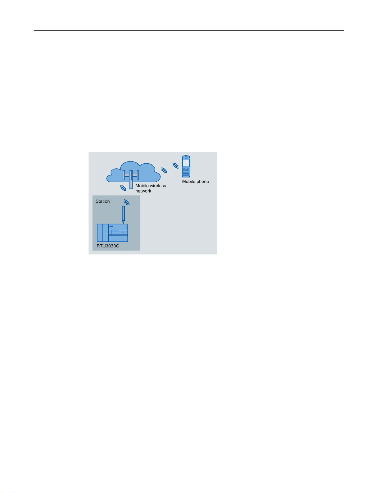
SMS / E-mail / FTP
Figure 1-1 Sending SMS messages by the RTU
Sending SMS messages / e-mail
The RTU can send messages (SMS / e-mails) for configurable events via program blocks or
using the logging function.
After a request from a mobile telephone, a diagnostics SMS message can be sent.
In the attachment of e-mails, you have the option of transferring the process image, the
diagnostics buffer or the current log file.
Receiving SMS messages
The RTU can be wakened out of the sleep mode by the telecontrol server or by the SMS
message of a mobile telephone or by SINEMA Remote Connect to establish a connection to
the communications partner
All mobile phones that are permitted to send a wake-up SMS message or the request for a
diagnostics SMS message to the RTU, must be enabled with the phone number of every
user in the WBM of the RTU ("Wake-up call allowed").
FTP file transfer
The RTU can transfer files to an FTP server in the LAN or reachable via the Internet via an
FTP block. The current log file, the entire process image or the diagnostics buffer can be
transferred.
RTU303xC
Operating Instructions, 06/2019, C79000-G8976-C382-06
17
Application and functions
1.2 Configuration examples
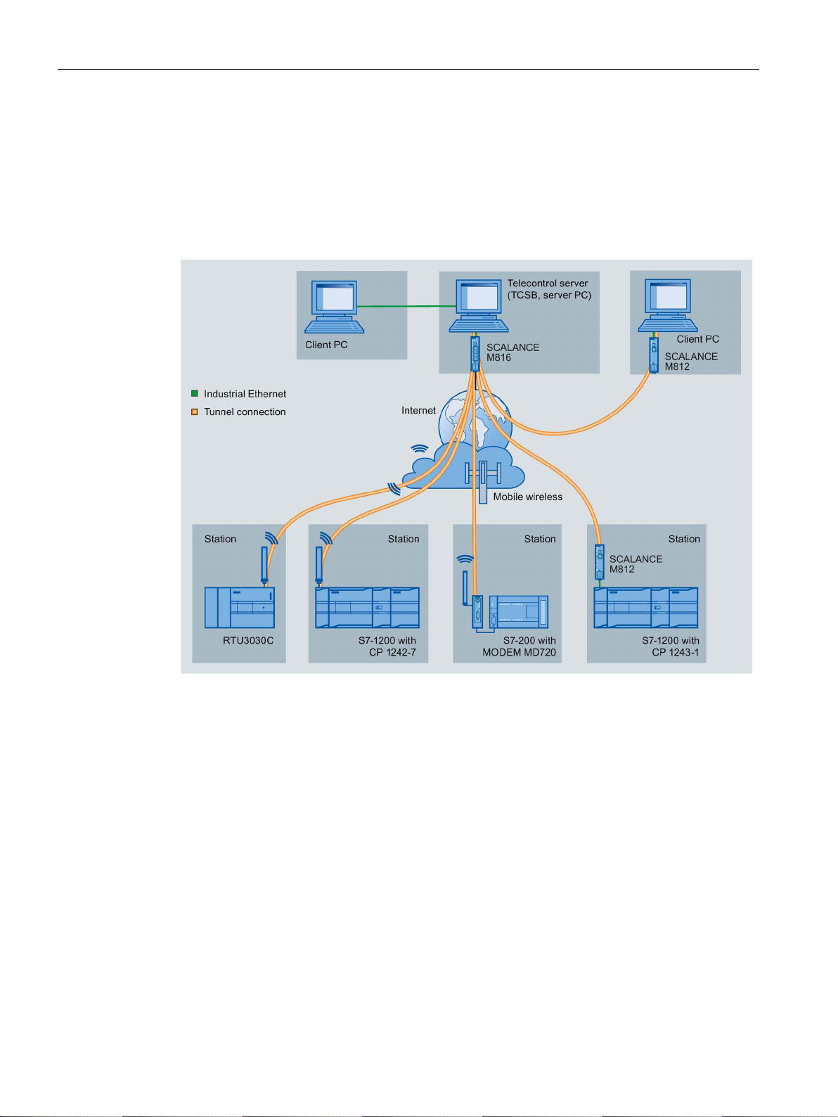
Telecontrol with the "TeleControl Basic" protocol
In the following example the RTU uses the "TeleControl Basic" protocol and communicates
via the mobile wireless network and the Internet with the teleconrol server (TCSB) in the
master station.
Using its integrated OPC server, the telecontrol server exchanges data with the OPC client
of the control center.
Figure 1-2 Communication of the RTU and other station types with a master station
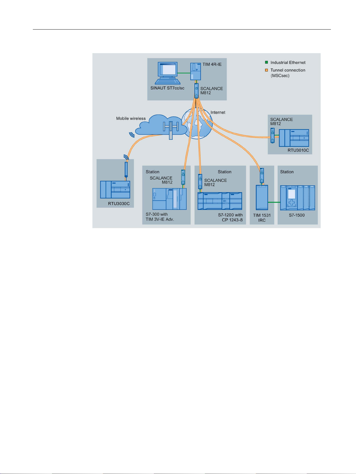
Telecontrol with the "ST7" protocol
In the following example the RTU communicates using the telecontrol protocol SINAUT ST7.
For secure communication, the RTU uses the transport protocol "MSCsec".
The figure contains two alternative connections:
● RTU3010C with connection via the Internet
● RTU3030C with connection via mobile wireless
It would also be possible to connect via LAN, only via the Internet or via an additional
underlying OpenVPN tunnel.
RTU303xC
18 Operating Instructions, 06/2019, C79000-G8976-C382-06
Application and functions
1.2 Configuration examples
Figure 1-3 Communication of the RTU3010C and RTU3030C with a master station TIM
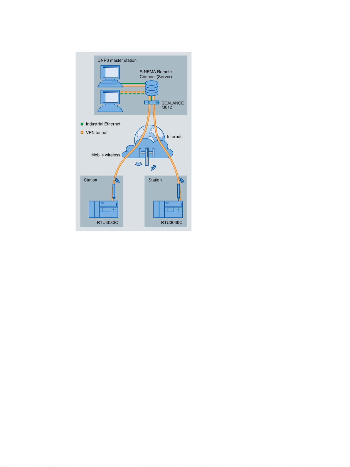
Telecontrol with the "DNP3" protocol
The following example contains a configuration with stations that communicate with the
master via the mobile wireless network and the Internet.
In this example, the master is duplicated. The two devices of the DNP3 master (main and
substitute master) in the master station are addressed by the RTU using one DNP3 address
but two different IP addresses.
The connections between stations and master are via an OpenVPN server "SINEMA
Remote Connect".
When using the DNP3 protocol, for example, SIMATIC PCS 7 TeleControl or the system of a
third-party provider can be used as the master. If you use SIMATIC PCS 7 TeleControl as
the DPN3 master, you require the necessary DPN3 driver.
RTU303xC
Operating Instructions, 06/2019, C79000-G8976-C382-06
19
Application and functions
1.2 Configuration examples
Figure 1-4 Communication of the RTU with a DNP3 master station
Telecontrol with the IEC protocol
The following example contains a configuration with stations that communicate with the
master via the mobile wireless network and the Internet.
The connections between stations and master are via an OpenVPN server "SINEMA
Remote Connect".
RTU303xC
20 Operating Instructions, 06/2019, C79000-G8976-C382-06

Application and functions
1.3 Modes and operating modes
Figure 1-5 Communication of the RTU with an IEC master station
When using the IEC protocol, the RTU can also communicate with a redundantly configured
master.
1.3 Modes and operating modes
Modes
The modes of the RTU are not configured explicitly but result from the configuration of the
communications partner and the existence of an SD card.
The RTU can be operated one or both of the following modes:
TeleControl
In the "TeleControl" mode, the RTU can send process data via the mobile wireless network
or via the LAN interface and an external router to a master station (see also "Communication
mode" below).
This mode is adopted when a communications partner (master station) is configured.
As an option, process data can be stored on an SD card. To do this logging must be enabled
in the WBM in "Operating mode".
RTU303xC
Operating Instructions, 06/2019, C79000-G8976-C382-06
21

Application and functions
1.3 Modes and operating modes
Logging
In the "Logging" mode the RTU has no communications partner in the master station.
Instead, the RTU stores the process data.
This operating mode is adopted when logging must be enabled in the WBM in "Operating
mode".
In the "Logging" mode, the RTU requires an SD card where it can store the process data.
The stored process data can be read out from the SD card or sent via the mobile wireless
network or the LAN interface and an external router. Cyclic sending is possible by e-mail or
FTP. You can load the data on a PC via the WBM.
Operating modes
The RTU can adopt the following operating modes:
● Sleep mode
● Update mode
● Communication mode
● Service mode
Sleep mode
In the energy-saving standard operating mode the updating of the inputs and outputs, the
communications functions, the LEDs and the self check function (see section Other services
and properties (Page 34)) of the RTU are turned off.
The RTU interrupts the sleep mode in the following situations:
● Pressing the button "WKUP" and changing to the service mode
● Configured change to the update mode (WBM > Operating mode)"
With the inputs, other specific update cycles can be configured (WBM > "Tags").
● Configured change to the communication mode (WBM > Operating mode)"
● Pending diagnostics message with configured change to the communication mode (WBM
> "Diagnostics" > "Notifications")
● Cyclic interruption of the sleep mode to fetch a wake-up SMS (WBM > "Operating mode")
● Occurrence of certain events:
– Creating a new log file with a configured change to the communication mode to
transfer the old log file
– Further events, refer to the section "Update mode".
In the "TeleControl" mode, the RTU in sleep mode has the greatest energy-saving potential
when using the "TeleControl Basic" protocol.
Update mode
The update mode is controlled by the configurable update cycle, refer to the section
Operating modes (Page 166).
RTU303xC
22 Operating Instructions, 06/2019, C79000-G8976-C382-06

Application and functions
1.3 Modes and operating modes
In the Update mode, the RTU runs through the following steps:
● Read the inputs and, if enabled, the GPS position (RTU3031C) that were configured for
the current cycle.
● Processing of the program blocks
● Writing the outputs
● Saving the process data in the send buffer when telecontrol communication is enabled
● Saving the process data data on the SD card (with Logging activated)
After updating, the RTU returns to sleep mode, or changes to the communication mode if
this is configured. The update cycle and communication cycle can also run independently of
each other.
In addition to the configured update cycle, the RTU changes from the sleep mode to the
update mode when configurable events occur. The following events can be configured:
● Value change at the analog input "AI0"
● Edge change at a digital input
● Triggering of timers of program blocks, for example with a pulse generator or with the
on/off delay.
● Manual value change of a tag in WBM
Note that configured events lead to higher current consumption.
Communication mode
In the Communication mode, the RTU performs the following tasks:
● Activating the internal mobile wireless modem or the LAN interface and an external router
(via configurable control outputs of the RTU)
● Sending the data messages to the configured communications partner in the master
station
● Sending stored messages / data (SMS messages, e-mails, FTP file transfer, Syslog)
● Synchronization of the time of day if configured.
● Diagnostics
In addition to the tasks listed above, in the communication mode a connection can be
established to the WBM of the RTU by the telecontrol server or the configuration PC. This
makes diagnostics of the RTU and maintenance work possible.
The times of the changeover to the communication mode can be configured as a cycle and
on the occurrence of events. After transferring data, the RTU returns to the sleep mode. As
long as there is no update cycle running.
Connection establishment as a result of receiving a wake-up SMS message from the
telecontrol server or from a mobile phone can be configured. Remember that this increases
the current consumption of the RTU. For more detailed information, refer to the section
Wake-up call / wake-up SMS (Page 240).
Service mode
The service mode is enabled by briefly pressing the (< 1 s) of the "WKUP" button.
RTU303xC
Operating Instructions, 06/2019, C79000-G8976-C382-06
23

Application and functions
1.4 Process connection - inputs / outputs
The changeover to the Service mode as the following effect:
● Turning on the LEDs that were turned off in the other operating modes to reduce energy
consumption.
● Activation of the LAN interface
With the LAN interface of the RTU activated, a configuration PC can access the Web
pages (WBM) of the RTU.
The Service mode is intended for commissioning and for service purposes on site, for
example, to replace the battery.
The service mode can be active parallel with the update mode and communication mode.
The service mode can also be activated permanently. Remember that this increases the
energy consumption of the RTU significantly.
1.4 Process connection - inputs / outputs
Inputs, outputs
The RTU provides the following inputs and outputs for the process connection:
● 8 digital inputs
The first two digital inputs can also be configured as fast counter inputs up to 5 kHz.
● 4 digital outputs, designed as bistable mechanical relays
● RTU3031C: 4 digital outputs, designed as fast electronic relays
● 4 analog inputs
The input AI0 can also be monitored in sleep mode.
● Up to 16 digital or analog inputs via the extension board
You will find details in the section Interfaces and connectors (Page 51).
1.5 Control functions
Control functions
The control functions of the RTU are implemented by creating a user program made up of
program blocks. The blocks are displayed graphically and programmed on integrated Web
pages (WBM), see section Program (Page 213).
The linking with inputs and outputs and the programming of function values is performed
conveniently with drop-down lists or by entering values.
RTU303xC
24 Operating Instructions, 06/2019, C79000-G8976-C382-06

Application and functions
1.6 Communications services
The following groups of program blocks are available:
● Logical functions
Logical AND / OR, NOT (inverter), exclusive OR
● Timer functions
Delay blocks, pulse generator, timer block
● Analog value functions
Threshold value and comparator blocks, arithmetic functions etc.
● Counter and summation blocks
Counter, flow, summation and volume blocks
● Blocks for messages
Sending by SMS, e-mail and FTP
● Relay blocks
Latching relays, current impulse relays, wiping relays, time relays
● Other blocks
Block for changing the operating state
For a description of the program blocks, refer to the section Program blocks (Page 249).
1.6 Communications services
Interfaces for communication
With firmware version V1, the RTU supports communication via mobile wireless (WAN
interface).
As of firmware version V2, the RTU also supports communication via LAN, optionally with an
external router. For the following communications services the interface (LAN/WAN) can be
set separately: Telecontrol, e-mail, FTP, NTP.
As of firmware version V3, connections to an OpenVPN server (or SINEMA RC) can be
made via LAN or WAN.
Exception: Connections with DynDNS are always via mobile wireless.
You will find a selection of routers in the appendix Router SCALANCE M (Page 368).
RTU303xC
Operating Instructions, 06/2019, C79000-G8976-C382-06
25

Application and functions
1.6 Communications services
Protocols for communication with a master station
Depending on the loaded firmware variant, the RTU supports one of the following protocols
for communication with a master station:
●
TeleControl Basic
This is a proprietary protocol of Siemens for telecontrol applications.
The IP-based communications protocol is used to connect the RTU to the application
TCSB. TCSB is installed on a PC in the master station, the telecontrol server. For the
version, see section Scope of delivery, accessories, requirements (Page 39).
Via the OPC-DA or OPC-UA server of TCSB, and OPC client can access the process
data of the RTU. For the TCSB manual, see /4/ (Page 388).
Apart from the RTU, several S7-1200 CPs also support the protocol. It allows especially
energy-saving operation since communications connections are only established
temporarily stop
●
SINAUT ST7
The RTU uses the ST7 protocol for communication with a master station TIM.
For communication with a PC application in the master station, the connection must run
via the master station TIM.
When communicating with a TIM module, the RTU uses the transfer protocol "MSCsec"
on the network layer (OSI layer 3). The S7 or MSC protocol cannot be used for
communication with a master station application.
RTU303xC
26 Operating Instructions, 06/2019, C79000-G8976-C382-06

Application and functions
NOTICE
Securing communication
1.6 Communications services
● DNP3
The RTU functions as a DNP3 station (Outstation).
Communication is based on the DNP3 SPECIFICATION Version 2.x (2007/2009).
The RTU is certified for the DNP3 conformity levels Level 1 and 2, but also supports
higher conformity levels.
For secure communication with the master, the connection can be established via a VPN
tunnel, see section Security functions for communication (Page 32).
• When using the LAN interface, select suitable means to make sure that there is
secure communication with the master, for example by using SCALANCE M routers.
• For direct use of the WAN interface without an underlying VPN connection, make
sure that the mobile wireless network is protected against access by third parties,
e.g. by using a private APN.
According to the specification "Supplement to Volume 2 - SECURE AUTHENTICATION",
the RTU supports secure authentication, see section DNP3 (Page 220).
You will find a detailed overview of the attributes and properties specified in the DNP3
protocol and supported by the RTU in the DNP3 device profile, see /2/ (Page 388).
You can find the supported object groups and variations in the section Data points
(Page 230).
Communications partners (DNP3 masters) of the RTU can be:
– SIMATIC PCS 7 TeleControl
– SIMATIC WinCC TeleControl
– A TIM module with DNP3 capability (TIM 3V IE DNP3 / TIM 4R IE DNP3)
For the manual of the TIM module see /8/ (Page 389).
– Third-party systems that support the DNP3 specification named above.
●
IEC 60870-5
The RTU functions as a substation (slave).
Communication is based on the specification IEC 60870-5 Part 104 (2006).
Communications partners of the RTU can be all master systems that support the
specification named above.
For secure communication with the master, the connection can be established via a VPN
tunnel, see section Security functions for communication (Page 32).
RTU303xC
Operating Instructions, 06/2019, C79000-G8976-C382-06
27

Application and functions
NOTICE
Securing communication
1.6 Communications services
• When using the LAN interface, select suitable means to make sure that there is
secure communication with the master, for example by using SCALANCE M routers.
• For direct use of the WAN interface without an underlying VPN connection, make
sure that the mobile wireless network is protected against access by third parties,
e.g. by using a private APN.
You will find a detailed overview of the attributes and properties specified in the IEC
specification and supported by the RTU in the IEC device profile, see /3/ (Page 388).
You can find the supported IEC type identifiers in the section Data points (Page 230).
When it ships, the RTU is loaded with the firmware variant for the "TeleControl Basic"
protocol.
Firmware for the protocols DNP3, IEC and ST7
To use these telecontrol protocols, you need to load the corresponding firmware variant on
the RTU.
You can obtain the suitable firmware file free of charge from Siemens Industry Online
Support:
● Link: (http://www.automation.siemens.com/aspa_app/)
Here, you will find a contact.
● Link: (https://support.industry.siemens.com/cs/ww/en/ps/21766/dl)
With this page, you can download the firmware.
The firmware version for the "TeleControl Basic" protocol loaded when the device was
delivered is then overwritten, but it can be loaded to the module again.
For information on loading firmware files, see section Loading firmware (Page 329).
RTU303xC
28 Operating Instructions, 06/2019, C79000-G8976-C382-06

Application and functions
1.6 Communications services
Other communication services
The RTU can send messages and data for configured event classes (diagnostics buffer
entries) either as SMS messages or as e-mails.
●
SMS (receive)
The following SMS messages can be received:
– Wake-up SMS message configured in the Configuration and Monitoring Tool (CMT) of
TCSB for establishing a connection to the telecontrol server
– Manually triggered wake-up SMS message from the Web server of TCSB for
establishing a connection to a PC (via the telecontrol server)
– Wake-up SMS from SINEMA Remote Connect
– Manual TeleService SMS optionally with deadline
– SMS message as request for a diagnostics SMS message
You enable receipt of SMS messages in the WBM, refer to the section SMS (Page 141).
●
SMS (sending)
The following SMS messages can be sent:
– SMS message if diagnostics messages occur, refer to the section Configuration
(Page 121).
– SMS message with event-related process data via program blocks, refer to the section
Sending SMS messages (Page 311).
– Diagnostics SMS message, refer to the section Diagnostics options (Page 325).
– SMS messages if certain events occur relating to the SD card or battery module
– SMS when the IP address changes on the WAN interface
RTU303xC
Operating Instructions, 06/2019, C79000-G8976-C382-06
29

Application and functions
1.6 Communications services
● E-mail (sending)
The following e-mails can be sent:
– E-mail if diagnostics messages occur, refer to the section Configuration (Page 121).
– E-mail with event-related process data via program blocks, refer to the section Send
e-mail (Page 312).
– E-mails with process data (log file) using the logging function, refer to the section
Logging (Page 169).
– E-mails if certain events occur relating to the SD card or battery module
– E-mail when the IP address changes on the WAN interface
In the attachment of an e-mail, there is the option of transferring the current process
image, the log file or the entire diagnostics buffer. The attachment is transferred
uncompressed or compressed as a ZIP archive.
You configure the access data and general settings for using the e-mail service in the
WBM, refer to the section E-mail (Page 145).
For information on the configurable security option "STARTTLS" when sending e-mails,
refer to the section Security functions for communication (Page 32).
You configure further parameters of notifications on the following WBM pages:
– Recipient of the messages, refer to the section Users / groups (Page 161).
– Message texts, refer to the section Texts (Page 196).
– For information on selecting the attachment of the e-mail, see section Configuration
(Page 121).
●
FTP (sending)
Transfer of FTP files via a program block to an FTP server reachable via LAN or the
Internet
The function corresponds to the FTP command "PUT".
An FTP file transfer is possible for the following data:
– Current log file
See section Logging (Page 169).
– The entire process image
– The entire diagnostics buffer
The file can be transferred uncompressed or compressed as a ZIP archive. For
uncompressed transfer, the file transfer can also be performed with the "Append"
function. When this is used, when the file being transferred arrives at the destination
location, the FTP server appends the file to an existing file of the same name, if present,
instead of overwriting it.
For information on the program block see section FTP file transfer (Page 313).
For information on the configurable security option when using FTP transfer see section
Security functions for communication (Page 32).
RTU303xC
30 Operating Instructions, 06/2019, C79000-G8976-C382-06
 Loading...