

SIMATIC RI45 PII Series,SIMATIC RI45 PII Tower,SIMATIC RI45 PII Desktop,SIMATIC RI45 PII Rack
Table of contents
 Loading...
Siemens SIMATIC RI45 PII Series,SIMATIC RI45 PII Tower,SIMATIC RI45 PII Desktop,SIMATIC RI45 PII Rack Product Information Bulletin
SIMATIC
RI45 PII
Product Information Bulletin
C79000-Z7076-C814-02

Safety Guidelines
!
!
This product information bulletin contains notices which you should observe to ensure your own
personal safety , as well as to protect the product and connected equipment. These notices are
highlighted in the manual by a warning triangle and are marked as follows according to the level
of danger:
Warning
indicates that death, severe personal injury or substantial property damage can result if proper
precautions are not taken.
Caution
indicates that minor personal injury or property damage can result if proper precautions are not
taken.
Note
draws your attention to particularly important information on the product, handling the product, or
to a particular part of the documentation.
Correct Usage
!
Trademarks
Please observe the following:
Note
Y ou can set up and operate your device in conjunction with the following instructions.
Only qualified personnel should be allowed to install and work on this equipment. Qualified
persons are defined as persons who are authorized to commission, to ground, and to tag
equipment, systems, and circuits in accordance with established safety practices and standards.
Warning
This device may only be used for the applications described in the catalog or technical description,
and only in connection with devices or components from other manufacturers which have been
approved or recommended by Siemens.
This product can only function correctly and safely if it is transported, stored and set up carefully and
correctly , and operated and maintained as recommended.
SIMA TIC R , SIMA TIC NETR and SIMA TIC HMIR are registered trademarks of SIEMENS AG.
Copyright E Siemens AG 1999 All Rights Reserved
The reproduction, transmission or use of this document or its contents is
not permitted without express written authority.
Offenders will be liable for damages. All rights, including rights created by
patent grant or registration of a utility model or design, are reserved.
Siemens AG
Bereich Automatisierungs- und Antriebstechnik
Geschaeftsgebiet Industrie Automatisierungssysteme
Postfach 4848, D-90327 Nuernberg
Siemens Aktiengesellschaft
Disclaimer of Liability
We have checked the contents of this manual for agreement with the
hardware and software described. Since deviations cannot be precluded
entirely , we cannot guarantee full agreement. However , the data in this
manual are reviewed regularly and any necessary corrections included in
subsequent editions. Suggestions for improvement are welcomed.
Technical data subject to change.
C79000Z7076C814
Printed in the Fed. Rep. of Germany

Contents
1 Safety Instructions 1-1. . . . . . . . . . . . . . . . . . . . . . . . . . . . . . . . . . . . . . . . . . . . . . . . . . . . .
1.1 General Notes 1-2. . . . . . . . . . . . . . . . . . . . . . . . . . . . . . . . . . . . . . . . . . . . . . . . . .
1.2 Notes on the CE Symbol 1-4. . . . . . . . . . . . . . . . . . . . . . . . . . . . . . . . . . . . . . . . .
1.3 Approvals for the USA and Canada (RI45 PII) 1-5. . . . . . . . . . . . . . . . . . . . . . .
1.3.1 FCC Approval for USA and Canada (RI45 PII) 1-6. . . . . . . . . . . . . . . . . . . . . .
2 Unpacking and Installing the RI45 PII 2-1. . . . . . . . . . . . . . . . . . . . . . . . . . . . . . . . . . . .
2.1 Device Models 2-2. . . . . . . . . . . . . . . . . . . . . . . . . . . . . . . . . . . . . . . . . . . . . . . . . .
2.2 Installing and Transporting the RI45 PII 2-3. . . . . . . . . . . . . . . . . . . . . . . . . . . . .
2.3 Hardware components of the RI45 PII 2-4. . . . . . . . . . . . . . . . . . . . . . . . . . . . . .
2.4 Installing Your PC in a 19” Cabinet or Rack (RI45 PII 19” Operation) 2-7. . .
2.5 Drives 2-8. . . . . . . . . . . . . . . . . . . . . . . . . . . . . . . . . . . . . . . . . . . . . . . . . . . . . . . . .
3 Setting Up and Operating the RI45 PII 3-1. . . . . . . . . . . . . . . . . . . . . . . . . . . . . . . . . . . .
3.1 Connecting the RI45 PII to the Power Supply 3-2. . . . . . . . . . . . . . . . . . . . . . .
3.2 Connecting I/O Devices 3-4. . . . . . . . . . . . . . . . . . . . . . . . . . . . . . . . . . . . . . . . . .
3.3 Keyboard 3-6. . . . . . . . . . . . . . . . . . . . . . . . . . . . . . . . . . . . . . . . . . . . . . . . . . . . . .
3.4 Starting Up Your PC for the First Time 3-7. . . . . . . . . . . . . . . . . . . . . . . . . . . . .
3.5 Electronic Manual 3-8. . . . . . . . . . . . . . . . . . . . . . . . . . . . . . . . . . . . . . . . . . . . . . .
3.6 Installing Adobe Acrobat 3-9. . . . . . . . . . . . . . . . . . . . . . . . . . . . . . . . . . . . . . . . .
3.7 Backing Up Hard Disk Data on Diskettes 3-9. . . . . . . . . . . . . . . . . . . . . . . . . . .
4 Expanding the RI45 PII 4-1. . . . . . . . . . . . . . . . . . . . . . . . . . . . . . . . . . . . . . . . . . . . . . . . . .
4.1 Opening the Unit 4-2. . . . . . . . . . . . . . . . . . . . . . . . . . . . . . . . . . . . . . . . . . . . . . . .
4.2 Components Visible After Opening the Unit 4-4. . . . . . . . . . . . . . . . . . . . . . . . .
4.3 Installing Memory Expansion Cards 4-7. . . . . . . . . . . . . . . . . . . . . . . . . . . . . . . .
4.4 Changing the Backup Battery 4-9. . . . . . . . . . . . . . . . . . . . . . . . . . . . . . . . . . . . .
4.5 Closing the Unit 4-9. . . . . . . . . . . . . . . . . . . . . . . . . . . . . . . . . . . . . . . . . . . . . . . . .
4.6 Options 4-10. . . . . . . . . . . . . . . . . . . . . . . . . . . . . . . . . . . . . . . . . . . . . . . . . . . . . . . .
5 Technical Specifications 5-1. . . . . . . . . . . . . . . . . . . . . . . . . . . . . . . . . . . . . . . . . . . . . . . .
5.1 Technical Specifications 5-2. . . . . . . . . . . . . . . . . . . . . . . . . . . . . . . . . . . . . . . . . .
Product Information Bulletin RI45 PII
C79000-Z7076-C814-02
iii

Contents
6 Error Diagnostics 6-1. . . . . . . . . . . . . . . . . . . . . . . . . . . . . . . . . . . . . . . . . . . . . . . . . . . . . . .
6.1 The PC Does not React to the ON/OFF Switch 6-2. . . . . . . . . . . . . . . . . . . . . .
6.2 Problems When Using Modules from Other Manufacturers 6-2. . . . . . . . . . . .
6.3 The Monitor Remains Dark 6-3. . . . . . . . . . . . . . . . . . . . . . . . . . . . . . . . . . . . . . .
6.4 The Screen Display Does not Appear or Drifts 6-4. . . . . . . . . . . . . . . . . . . . . . .
6.5 No Mouse Pointer Appears on the Screen 6-4. . . . . . . . . . . . . . . . . . . . . . . . . .
6.6 The Clock Time and/or the Date in Your PC Is Incorrect 6-5. . . . . . . . . . . . . .
6.7 Rebooting Your Hard Drive (Data Deleted) 6-5. . . . . . . . . . . . . . . . . . . . . . . . . .
6.8 An Error Message Appears on the Screen 6-6. . . . . . . . . . . . . . . . . . . . . . . . . .
6.9 RI45 PII Self-Test Prior to Booting 6-7. . . . . . . . . . . . . . . . . . . . . . . . . . . . . . . . .
7 Service Representatives 7-1. . . . . . . . . . . . . . . . . . . . . . . . . . . . . . . . . . . . . . . . . . . . . . . .
7.1 Regional Repair Centers 7-3. . . . . . . . . . . . . . . . . . . . . . . . . . . . . . . . . . . . . . . . .
iv
Product Information Bulletin RI45 PII
C79000-Z7076-C814-02

Safety Instructions
1
Chapter
Overview
This chapter provides you with mandatory safety instructions which you must
follow when you operate your PC and its components.
This device corresponds to the relevant safety measures according to IEC,
EN, VDE, UL, and CSA. If you have questions about the permissibility of
the installation in the designated environment, please contact our service
representative. Chapter 7 contains the service address locations.
Product Information Bulletin RI45 PII
C79000-Z7076-C814-02
1-1

Safety Instruction
s
1.1 General Notes
Transport
Installation
Power Connection
We recommend that you transport the device only in the original packaging
(protection against shock and impact).
Condensation can occur if the device is transported from a cold environment
into the operating area. The device must be dry prior to startup. You must
allow for an acclimatization time of at least two hours.
Please observe the notes on ambient conditions in the section entitled
“Technical Specifications,” and the installation notes of this manual when
installing and operating the device.
Be sure the fan ventilation slots are open so that a sufficient amount of air
can be drawn in to cool the housing interior.
The sliding door in front of the drives on the front side must be kept closed
for safety reasons (fire protection according to UL 1950/EN 60950). You may
open the sliding door only to service the drives. You must not remove the
sliding door.
Check whether the device’s set supply voltage is the same as the local supply
voltage.
This device is equipped with a safety-tested power supply cable. You may
connect this device only to a grounding outlet with a grounding contact.
Make certain that the socket outlet on the device or the grounding contact for
the building wiring system is freely accessible.
The mains switch does not separate the device from the power system. To
establish a complete power separation, you must disconnect the power plug
(inlet connector on the back of the device). This location must be accessible.
A central isolating switch must be present for cabinet mounting.
Install the cables so that no one can step on them or trip over them. When
you connect the device, adhere to the relevant instructions in the Product
Information Bulletin.
Do not connect or disconnect power supply cables and data transmission lines
during thunderstorms.
In emergency situations (for example, damaged housing, damaged operator
elements, a damaged power supply cable, ingress of liquids or foreign
particles), switch off the device. Disconnect the power plug and inform the
responsible service personnel.
The PC must be switched off when you connect or disconnect I/O devices
(keyboard, mouse, printer, etc.). You can damage the PC if you do not adhere
to these instructions.
1-2
Product Information Bulletin RI45 PII
C79000-Z7076-C814-02

Safety Instruction
s
Repairs
ESD
Guidelines
Only authorized personnel are permitted to repair the device. Unauthorized
opening and improper repairs on the device can result in significant danger to
the user.
Before you open the device, first switch it off and then disconnect the power
plug.
Install only system expansion devices provided for this computer. If you
install other expansion devices, you can damage the system or violate the
safety requirements and regulations for radio interference suppression.
Contact your technical support team or where you purchased your PC to find
out which system expansion devices may safely be installed.
If you install or exchange system expansions and damage your PC, the
warranty becomes void.
The following sticker can be used to identify modules with ESD
(electrostatically-sensitive devices):
If you handle modules with ESD, it is essential that you adhere to the
following guidelines:
S Before you work with modules with ESD, you must statically discharge
yourself (for example, through contact with a grounded object).
S Devices and tools you use must be free of a static charge.
S Disconnect the power plug before you connect or disconnect modules
with ESD.
S Touch modules with ESD on the edge only.
S Do not touch any wiring posts or conductors on a module with ESD.
Product Information Bulletin RI45 PII
C79000-Z7076-C814-02
1-3

Safety Instruction
s
1.2 Notes on the CE Symbol
The following applies to the SIMATIC product described in this manual:
EMC Directive
Low-Voltage
Directive
Declaration of
Conformity
In accordance with the EU Directive 89/336/EEC “Electromagnetic
Compatibility.” In accordance with the CE label for this product, the
following areas of application are relevant:
Application Requirements
Area
Domestic, business and
commercial areas, as well as
small businesses
Industrial area EN 50081-2: 1993 EN 50082-2: 1995
Emitted Interfer ence Immunity
EN 50081-1: 1992 EN 50082-1: 1992
1)
This product complies with the reqirements of the EU Directive 73/23/EEC
“Low-Voltage Directive.” Conformance with this standard has been verified
according to EN 60950.
The EU declarations of conformity and the relevant documentation are held
at the disposal of the competent authorities at the address below:
Siemens Aktiengesellschaft
Bereich Automatisierungs- und Antriebstechnik
A&D AS E 4
Postfach 1963
D-92209 Amberg
Germany
Observing the
Installation
Guidelines
Connecting
Peripherals
Products not bearing the CE label fulfill the requirements and standards as
specified in the section on “Technical Specifications.”
The installation guidelines and safety instructions specified in the
documentation must be observed during startup and operation.
The requirements regarding noise immunity (EN50082-2:1995) are met when
you connect a peripheral switable for an industrial environment.
Note
Any other devices which are connected to this product must also be radio
interference suppressed according to the German Ministry for Post and Telecommunications provision 1046/84 and 243/91 or European Economic Community Directive 89/336/EEC. Products which fulfil these specifications
carry a manufacturer ’s certificate, the corresponding BZT (German government body for telecommunications approvals) approval or the CE symbol.
Products which do not fulfil these requirements may only be employed with
special permission from the BZT.
1)
does not apply to the RI45 PII T ower
1-4
Product Information Bulletin RI45 PII
C79000-Z7076-C814-02
Underwriters Laboratories (UL) to standard UL 1950, Report E11 5352 and
Safety Instruction
s
ISO 9001
Certificate
The quality assurance system for the whole product process (development,
production, and marketing) fulfils the requirements of ISO 9001 (corresponds
to EN29001: 1987).
This has been certified by the German society for the certification of quality
management systems (DQS).
EQ-Net certificate no.: 1323-01
1.3 Approvals for the USA and Canada (RI45 PII)
UL/CSA Approval
C
Important for the USA and Canada:
The following labels indicate that the relevant approval is available for the
device bearing the label:
Underwriters Laboratories (UL) to standard UL 1950
Underwriters Laboratories (UL) to Canadian standard C22.2 No. 950
C US
NRTL
Underwriters Laboratories (UL) to standard UL 1950, Report E11 5352 and
to Canadian standard C 22.2 No.950
UL Recognition Mark
Canadian Standard Association (CSA) to standard C22.2. No. 950
Canadian Standard Association (CSA) to American standard UL 1950
Product Information Bulletin RI45 PII
C79000-Z7076-C814-02
1-5

Safety Instruction
s
1.3.1 FCC Approval for USA and Canada (RI45 PII)
Federal Communications Commission
Radio Frequency Interference Statement
This equipment has been tested and found to comply with the limits for a Class A digital device, pursuant to Part
15 of the FCC Rules. These limits are designed to provide reasonable protection against harmful interference
when the equipment is operated in a commercial environment. This equipment generates, uses, and can radiate
radio frequency energy and, if not installed and used in accordance with the instruction manual, may cause
harmful interference to radio communications. Operation of this equipment in a residential area is likely to cause
harmful interference in which case the user will be required to correct the interference at his own expense.
Shielded Cables
Shielded cables must be used with this equipment to maintain compliance with FCC regulations.
Modifications
Changes or modifications not expressly approved by the manufacturer could void the user’s authority to operate
the equipment.
Conditions of Operations
This device complies with Part 15 of the FCC Rules. Operation is subject to the following two conditions: (1) this
device may not cause harmful interference, and (2) this device must accept any interference received, including
interference that may cause undesired operation.
Canadian Notice
This equipment does not exceed the Class A limits for radiated emissions as described in the Radio Interference
Regulations of the Canadian Department of Communications.
A vis Canadien
Le présent appareil numérique n’émet pas de bruits radioélectriques dépassant les limites applicables aux
appareils numériques de la Classe A prescrites dans le Réglement sur le brouillage radioélectrique édicté par le
Ministère des Communications du Canada.
1-6
Product Information Bulletin RI45 PII
C79000-Z7076-C814-02

Unpacking and Installing the RI45 PII
2
Chapter Overview
This chapter describes how to install the RI45 PII and contains all the
information you need to know about its most important components:
S Device models
S Installing and transporting
S Hardware components/interfaces
S Keyboard
S Installing your PC in a 19” cabinet or rack (RI45 PII 19” operation)
S Drives.
Product Information Bulletin RI45 PII
C79000-Z7076-C814-02
2-1
Unpacking and Installing the RI45 PII
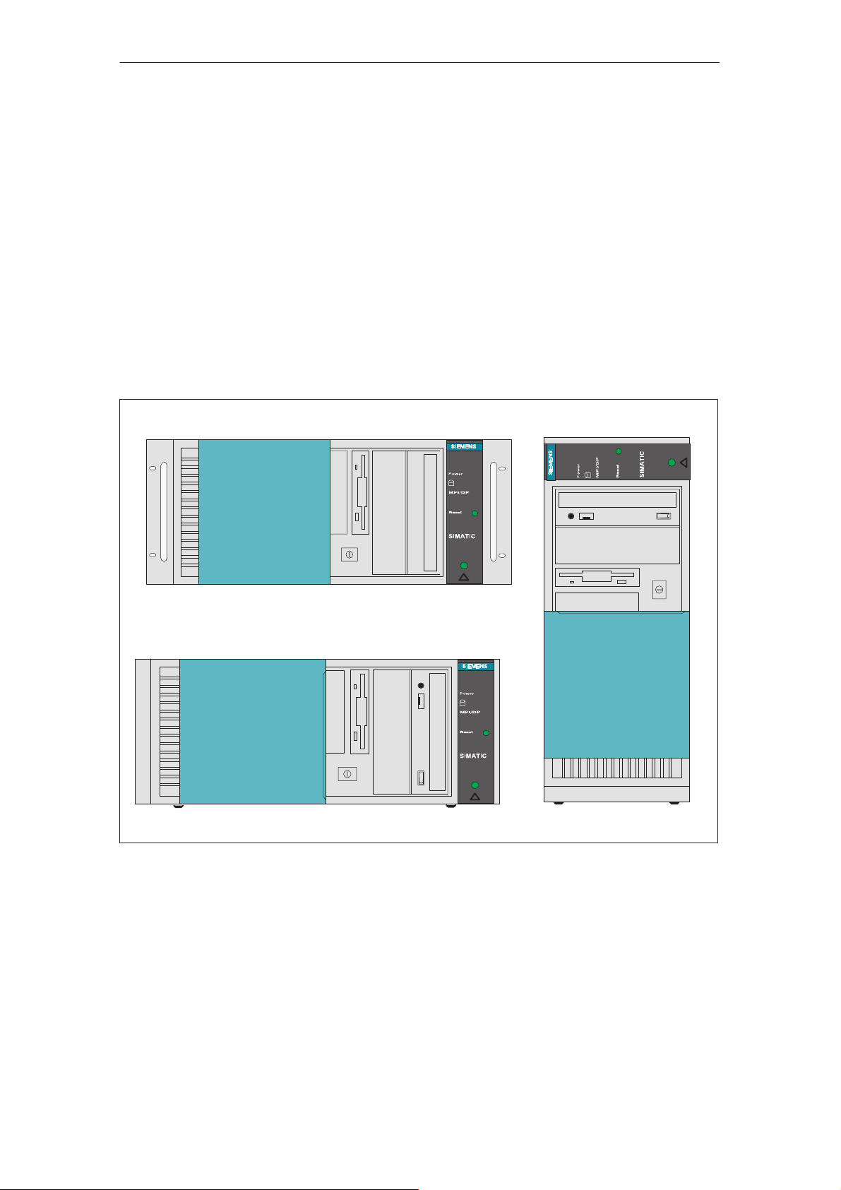
2.1 Device Models
The SIMATIC PC RI45 PII is available in the following three models:
Rack
Tower
Desktop
Rack
This model is designed to be installed in a 19” cabinet or mounting rack; it is
equipped with a module retainer and an air filter.
This model is designed for office use; it is equipped with a sound card and is
also supplied with a keyboard and a mouse.
This model is designed for table-top use; it is only available as a PCS7
device.
Tower
!
PC RI45 PII
PC RI45 PII
!
Desktop
Figure 2-1 Device Models of the RI45 PII
PC RI45 PII
!
2-2
Product Information Bulletin RI45 PII
C79000-Z7076-C814-02

2.2 Installing and Transporting the RI45 PII
Unpacking and Installing the RI45 PII
Unpacking the
RI45 PII
!
Unpack your RI45 PII as follows:
1. Remove the packing.
2. Do not throw the original packing away. Keep it in case you have to
transport the unit again sometime in the future.
3. Check with the packing list to make sure no components are missing.
4. Please keep the documentation in a safe place. It contains important
information on the operation of your RI45 PII.
5. Check the packing and its contents for any shipping or transport damage.
6. Please inform your local dealer of any shipping or transport damages and
of outstanding items indicated on the packing list.
Caution
Risk of mechanical damage!
When transporting your RI45 PII in cold weather when it may be exposed to
extreme variations in temperature, make sure that no moisture or
condensation can form on or in the unit.
The unit should be allowed to reach room temperature slowly before it is started
up. If condensation has formed, the unit should be left for about 12 hours before
being switched on.
Installing your
RI45 PII
Transport
Fill the serial number of your RI45 PII in the table below. If your device has
been stolen and repair work is required the repair and maintenance centers
can only identify it by its serial number.
Serial number RI45 PII
Installing the tower:
Proceed as follows:
1. Place your device on a horizontal and even surface.
Do not cover the ventilating slots.
2. Place the monitor, keyboard, and mouse in the most convenient position.
3. Connect the monitor, keyboard, and mouse.
Despite the fact that the RI45 PII is of rugged design, its internal components
are sensitive to severe vibrations or shock. You must therefore protect your
RI45 PII against severe mechanical stressing when transporting it. Use the
original packing material if you have to ship the programming device from
one location to another.
F No.:
Product Information Bulletin RI45 PII
C79000-Z7076-C814-02
2-3
Unpacking and Installing the RI45 PII
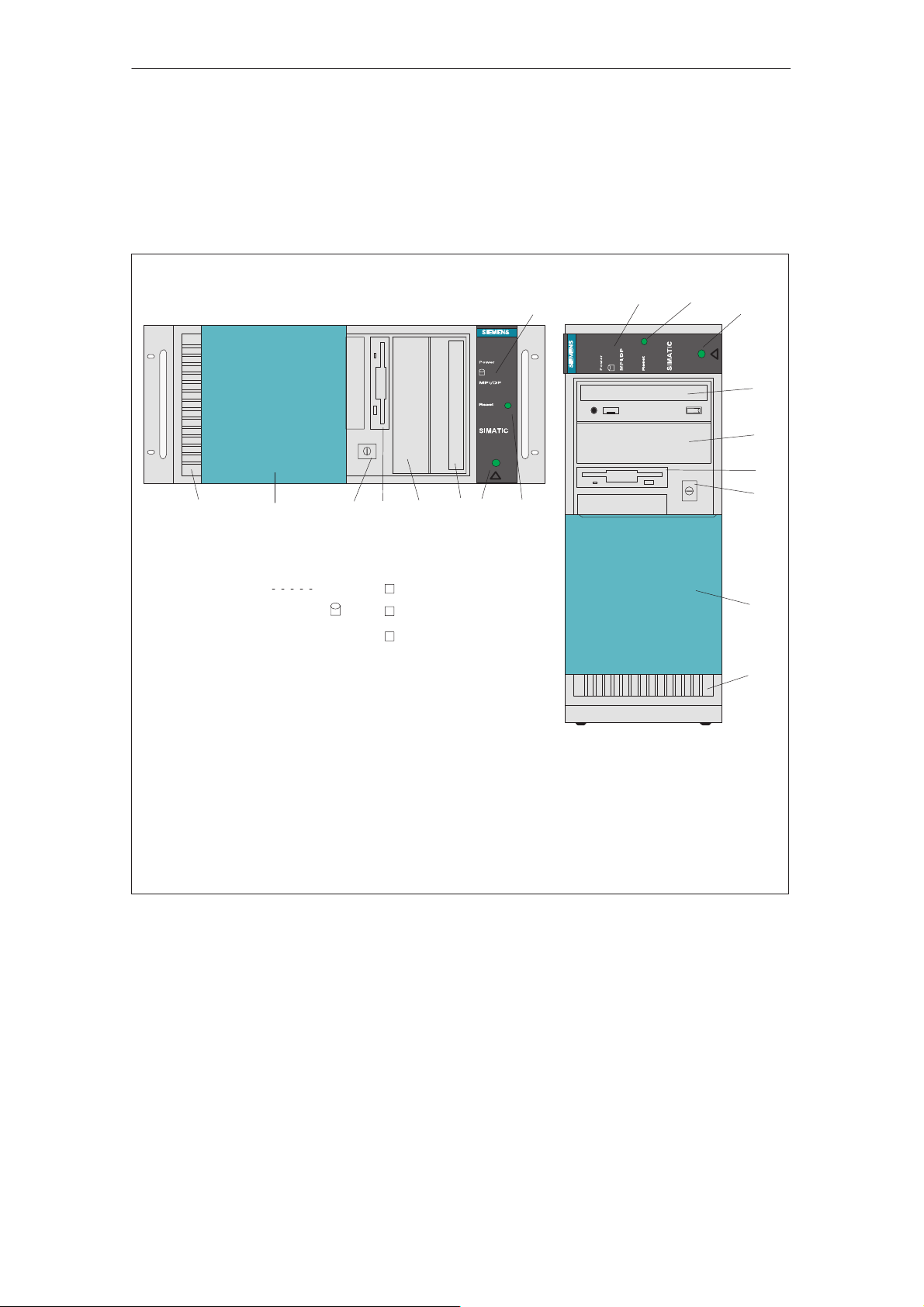
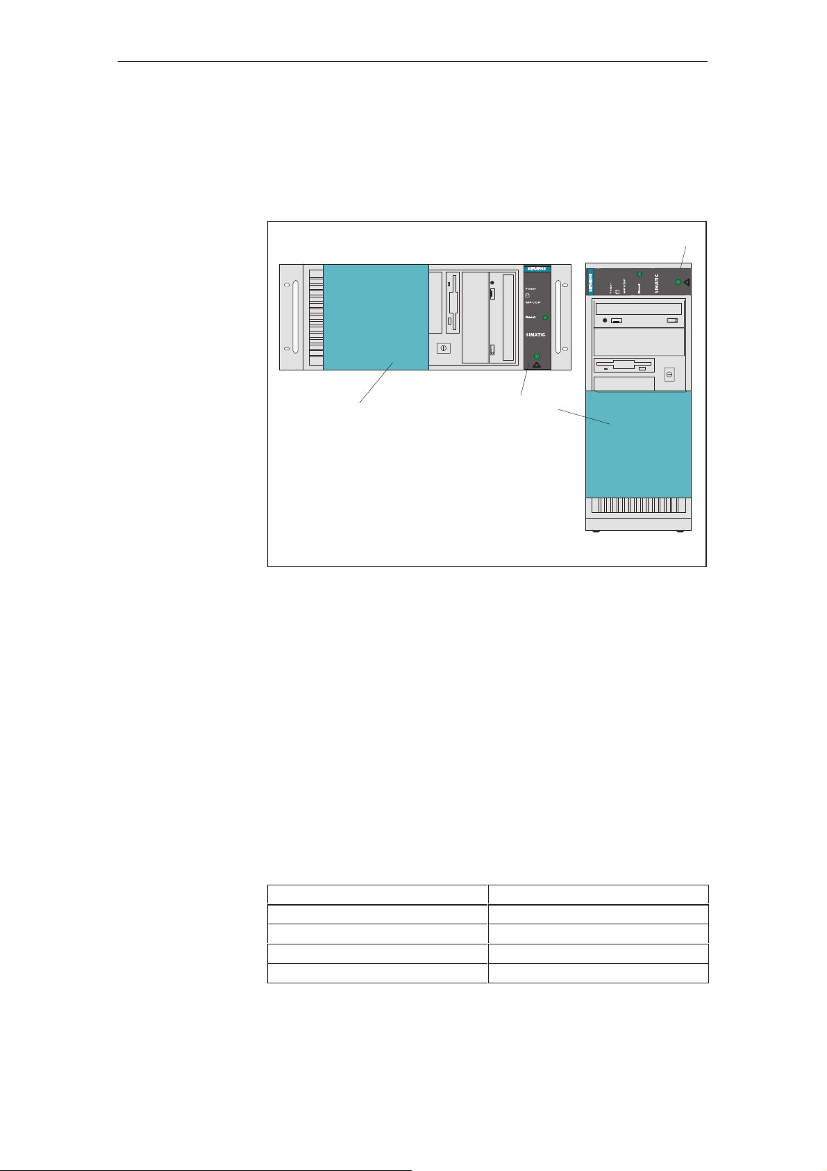
2.3 Hardware components of the RI45 PII
Front
Rack
9 8 7 6
1 LED displays
All important operator controls and displays are located behind the drive
cover on the front of the unit.
21
!
PC RI45 PII
4
5
Power
Power LED
Hard disk access
MPI/DP
MPI/DP port
RUN (with SafeCard only)
TEMP (with SafeCard only)
1
PC RI45 PII
!
32
Tower
3
4
5
6
7
8
9
2 Reset button
3 Lock for drive cover (access protection)
4 CD-ROM drive
5 Free slot
6 Diskette drive
7 On/Off switch
8 Protective cover for disk drive
9 V entilating slots
Figure 2-2 Front of the RI45 PII
2-4
Product Information Bulletin RI45 PII
C79000-Z7076-C814-02
Unpacking and Installing the RI45 PII
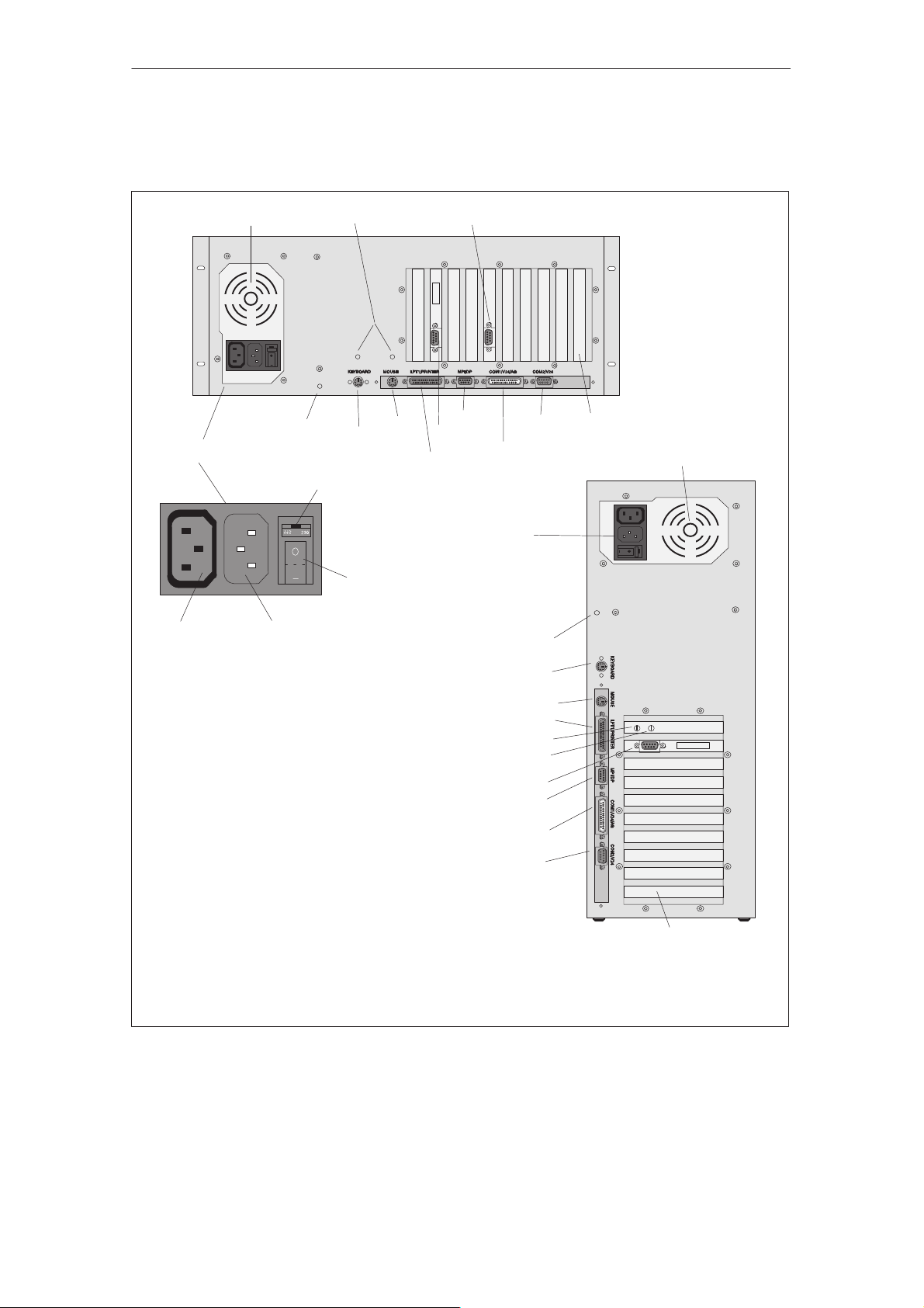
Rear Panel
(Connectors)
14
All the power supply connectors and interface ports for connecting to
external devices are located on the rear panel of the RI45 PII.
1
B
13
11
12
Supply voltage selector switch
B
On/Off switch
152
8
9
10
6
7
14
5
1
B
Power supply
connector
socket (out)
Power supply
connector
socket (in)
1 Cooling fan
2 Strain relief device (rack only)
3 Microphone (tower only)
4 Loudspeaker (tower only)
5 Dummy plates covering expansion slots
6 COM2
7 COM1
8 MPI/DP
9 VGA
10 LPT1
11 PS/2 mouse
12 PS/2 keyboard
13 Grounding studs
14 Supply voltage selector switch
15 Relay (with SafeCard only)
Figure 2-3 Rear Panel with Connectors and Ports
13
12
11
10
3
4
9
8
7
6
5
Product Information Bulletin RI45 PII
C79000-Z7076-C814-02
2-5
V.24 /
Unpacking and Installing the RI45 PII
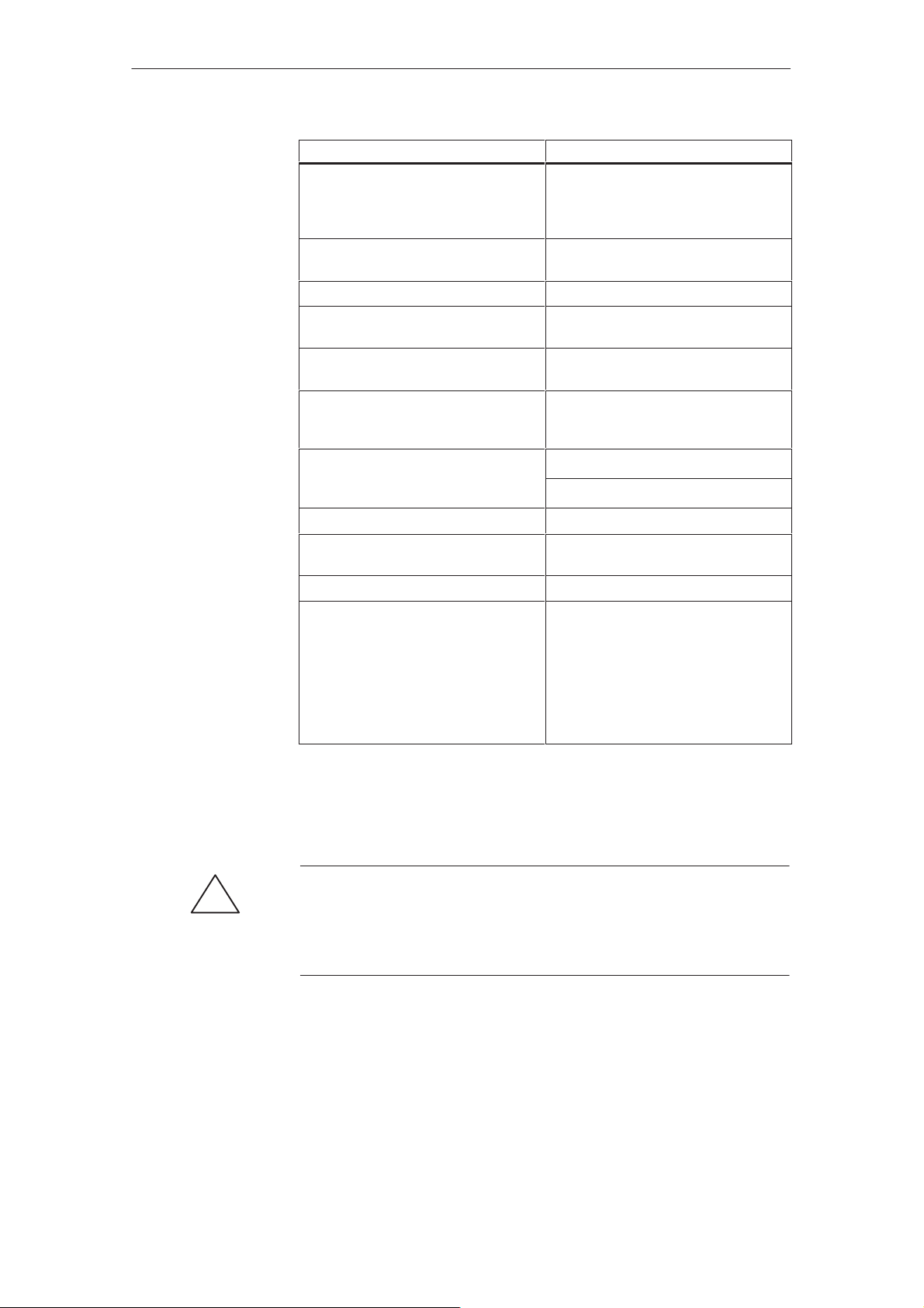
Ports and Connectors Function
Power supply connector Input
Power supply connector Output
PS/2 keyboard Connection for keyboard (trackball
PS/2 mouse Connection for PS/2 mouse
LPT 1 printer
Parallel interface
MPI/DP multipoint interface (RS485)* Connection for S7 programmable
COM 1
V.24/MODEM/PLC
Serial port
COM 2
mouse
Serial port
VGA Interface Connection for external monitor
Loudspeaker (RI45 PII T ower only) Connection for external stereo
Microphone (RI45 PII T ower only) Connection for microphone (mono)
Relay output (with SafeCard only) Connection of a signaling unit to the
Connection for power supply
(120/240V AC)
Connection for external monitor
(120/240V AC)
supported)
Connection for printer with parallel
interface
(compatible with CP 5611)
Connection for S5 programmable
controller
Connection for serial mouse
Connection for serial printer
loudspeaker
“SafeCard” monitoring module.
T echnical data:
Switching voltage DC: max. 60V
Switching current DC : max. 1A
Switching power DC : max. 30W
Limiting continuous
current DC : max. 1A
Ventilating Slots
!
* Galvanic isolation within the safety extra-low voltage circuit (SELV)
The raised air outlet slots for ventilation are located at the front and back
side. These slots must not be covered in any way.
Caution
Risk of overheating!
If you cover up the slots for the inlet and outlet air in any way, there is a risk
that your RI45 PII will be damaged.
2-6
Product Information Bulletin RI45 PII
C79000-Z7076-C814-02
Unpacking and Installing the RI45 PII
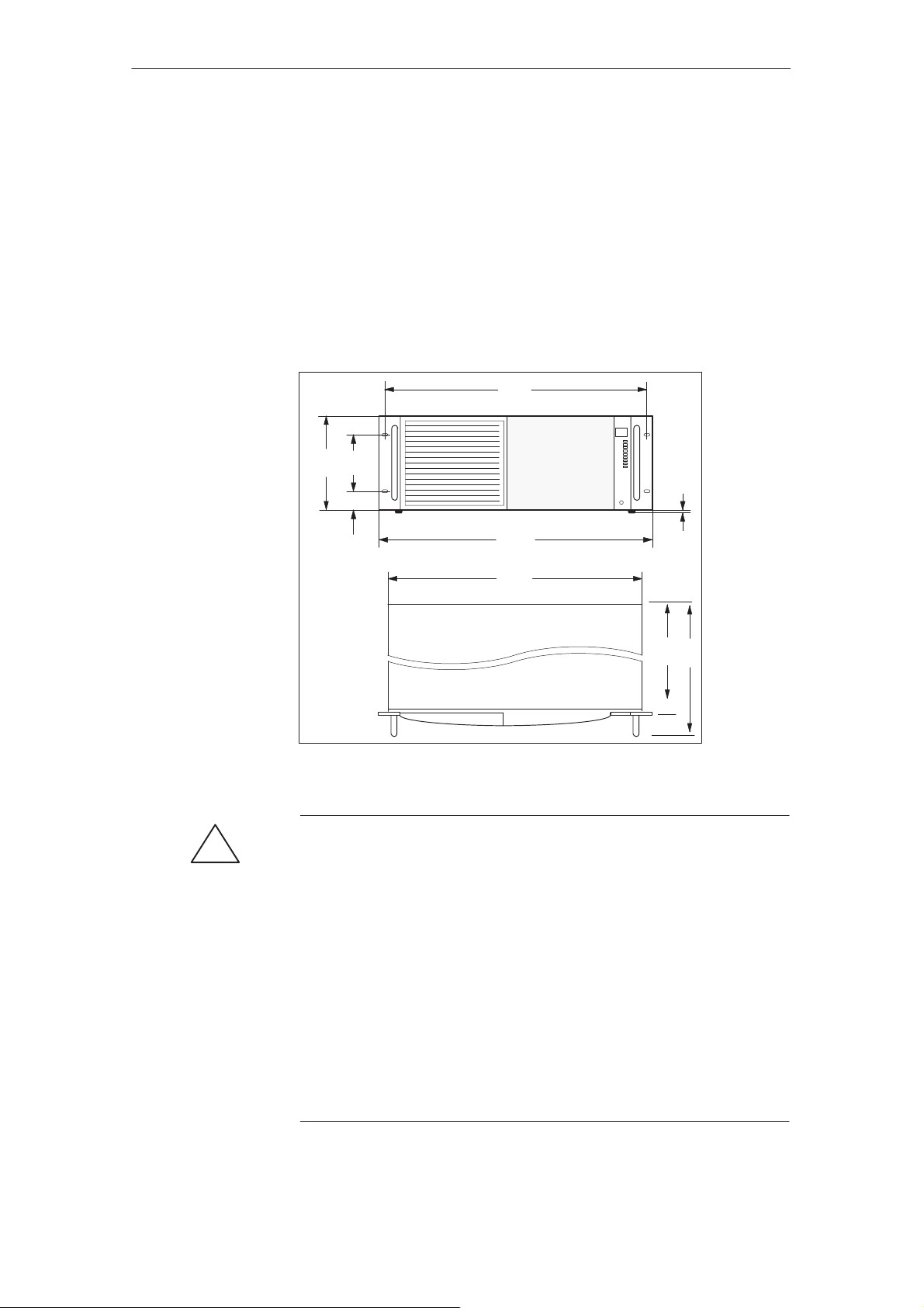
2.4 Installing Your PC in a 19” Cabinet or Rack (RI45 PII 19” Operation)
Layout
The installation height for your SIMATIC PC RI45 PII is only four ET
(height units = 177 mm, Figure LEERER MERKER). Therefore, special
installation assemblies are not required for installing this computer in a 19”
cabinet or rack. You must use four screws to fix the computer into position on
the cabinet’s braces. However, you should under no circumstances mount the
computer just on these screws (without rack slide rails). Use the respective
manufacturer’s cabinet or rack slide rails or L-sections. Contact your cabinet
supplier directly regarding cabinet or rack installation.
465
(18,31)
SIEMENS
(4,61)
101
177
(3,98)
(0,39)
38
(1,5)
483
(19,02)
448
(17,64)
10
(17,24)
438
482
(18,98)
All dimensions in mm
All dimensions ( ) in inches
Figure 2-4 SIMATIC PC RI45 PII Installation Dimensions
Warning
!
Avoid extreme ambient conditions as far as possible. Protect your SIMATIC
PC from dust, moisture, and heat. (Refer to the “System Unit” section in the
Technical Description.)
Mount the device as safely as possible to prevent any danger (for example,
by falling over).
The clearance around the system unit must be at least 200 mm at the front
and rear, so that the system unit is sufficiently ventilated.
Make certain that the ventilation slots for the system unit and the monitor
are not covered.
Make certain that the sliding door in front of the drives is closed during
operation. If the sliding door is not closed, insufficient air is drawn through
the ventilation slots to cool the interior of the system unit.
Product Information Bulletin RI45 PII
C79000-Z7076-C814-02
2-7
Unpacking and Installing the RI45 PII
2.5 Drives
Disk Drive Cover
The disk drives of your RI45 PII are protected against dirt penetration by a
sliding cover.
PC RI45 PII
PC RI45 PII
!
1
2
1 Lock for disk drive cover
2 Disk drive cover
2
1
!
Diskette Drive
Drive Types
Types of Diskette
Figure 2-5 Disk Drive Cover
S Open the disk drive cover to gain access to the drives and the power
switch.
S Slide the cover down, so that the disk drives and the power switch are
accessible.
S For improved ventilation and protection against dirt, the cover should be
closed during operation.
You can store programs and data on diskettes with the disk drive and load
them from diskettes into the RI45 PII.
The RI45 PII is equipped with the following drives as standard:
You can use the following diskettes:
Double-Sided High-Density Diskette Double-Sided Double-Density Diskette
3.5 in. 3.5 in.
1.44 Mbytes (135 TPI) 720 Kbytes
80 tracks per side 80 tracks per side
RI recognizes diskettes by their coding RI recognizes diskettes by their coding
2-8
Product Information Bulletin RI45 PII
C79000-Z7076-C814-02
Loading...