

Page 1
SIMATIC RF-DIAG
_
_________________
_
_
_________________
_
_
_________________
_
_
_________________
_
_
_________________
_
_
_________________
_
_
_________________
_
_
_________________
_
RFID systems
SIMATIC Ident
SIMATIC RF-DIAG
Operating Manual
09/2012
C79000-G8976-C292-01
Introduction
1
Description
2
Connecting hardware
3
Software installation
4
Operating the software
5
Application Examples
6
Error and system messages
7
Appendix A
A
Page 2
Siemens AG
Industry Sector
Postfach 48 48
90026 NÜRNBERG
GERMANY
Order number: C79000-G8976-C292
Ⓟ 09/2012 Technical data subject to change
Copyright © Siemens AG 2012.
All rights reserved
Legal information
Warning notice system
This manual contains notices you have to observe in order to ensure your personal safety, as well as to prevent
damage to property. The notices referring to your personal safety are highlighted in the manual by a safety alert
symbol, notices referring only to property damage have no safety alert symbol. These notices shown below are
graded according to the degree of danger.
DANGER
indicates that death or severe personal injury will result if proper precautions are not taken.
WARNING
indicates that death or severe personal injury may result if proper precautions are not taken.
CAUTION
indicates that minor personal injury can result if proper precautions are not taken.
NOTICE
indicates that property damage can result if proper precautions are not taken.
If more than one degree of danger is present, the warning notice representing the highest degree of danger will
be used. A notice warning of injury to persons with a safety alert symbol may also include a warning relating to
property damage.
Qualified Personnel
The product/system described in this documentation may be operated only by personnel qualified for the specific
task in accordance with the relevant documentation, in particular its warning notices and safety instructions.
Qualified personnel are those who, based on their training and experience, are capable of identifying risks and
avoiding potential hazards when working with these products/systems.
Proper use of Siemens products
Note the following:
WARNING
Siemens products may only be used for the applications described in the catalog and in the relevant technical
documentation. If products and components from other manufacturers are used, these must be recommended
or approved by Siemens. Proper transport, storage, installation, assembly, commissioning, operation and
maintenance are required to ensure that the products operate safely and without any problems. The permissible
ambient conditions must be complied with. The information in the relevant documentation must be observed.
Trademarks
All names identified by ® are registered trademarks of Siemens AG. The remaining trademarks in this publication
may be trademarks whose use by third parties for their own purposes could violate the rights of the owner.
Disclaimer of Liability
We have reviewed the contents of this publication to ensure consistency with the hardware and software
described. Since variance cannot be precluded entirely, we cannot guarantee full consistency. However, the
information in this publication is reviewed regularly and any necessary corrections are included in subsequent
editions.
Page 3

SIMATIC RF-DIAG
Operating Manual, 09/2012, C79000-G8976-C292-01
3
Table of contents
1 Introduction................................................................................................................................................ 5
1.1
Preliminary information ..................................................................................................................5
1.2
Abbreviations and naming conventions .........................................................................................6
2
Description................................................................................................................................................. 7
2.1
Requirements and notices .............................................................................................................7
2.2
Area of application and scenarios..................................................................................................8
2.3
Components of the product and ordering data ..............................................................................9
3
Connecting hardware............................................................................................................................... 11
3.1
The PC adapter for SIMATIC RF-DIAG.......................................................................................12
3.1.1
Description ...................................................................................................................................12
3.1.2
Pin assignment of the RS-422 interface ......................................................................................13
3.1.3
Technical specifications ...............................................................................................................16
3.1.4
Dimension drawing ......................................................................................................................18
3.1.5
Certificates and approvals ...........................................................................................................19
3.2
Connecting the hardware.............................................................................................................19
3.2.1
Connecting an Ethernet-based reader.........................................................................................19
3.2.2
Connecting a serial reader...........................................................................................................21
4
Software installation................................................................................................................................. 23
4.1
Installing the software ..................................................................................................................23
4.2
Installation and use of the USB driver .........................................................................................23
4.3
Starting the software ....................................................................................................................25
5
Operating the software ............................................................................................................................ 29
5.1
The log area.................................................................................................................................30
5.2
Tab overview................................................................................................................................31
5.3
The tabs of the RF640R/RF670R readers...................................................................................32
5.3.1
The "Info" tab ...............................................................................................................................32
5.3.2
The "Tag Data" tab.......................................................................................................................34
5.3.3
The "IO" tab..................................................................................................................................36
5.3.4
The "RSSI" tab.............................................................................................................................38
5.3.5
The "Tag Events" tab ...................................................................................................................41
5.4
The tabs of the RF620R/RF630R readers...................................................................................43
5.4.1
The "Info" tab ...............................................................................................................................43
5.4.2
The "Tag Data" tab.......................................................................................................................45
5.4.3
The "RSSI" tab.............................................................................................................................48
5.4.4
The "Power Ramp" tab ................................................................................................................51
5.4.5
The "Tag List" tab.........................................................................................................................55
5.4.6
The "Parameters" tab...................................................................................................................58
Page 4

Table of contents
SIMATIC RF-DIAG
4 Operating Manual, 09/2012, C79000-G8976-C292-01
5.4.7 The "VSWR" tab.......................................................................................................................... 62
5.4.8 The "Firmware-Update" tab......................................................................................................... 64
6
Application Examples .............................................................................................................................. 65
6.1
Scenarios for use of the PC adapter for RF-DIAG...................................................................... 65
6.2
Example of an application "optimize antenna position" .............................................................. 67
6.3
Example of an application "Determining transmit power"........................................................... 69
6.4
Example of an application "Setting the Power Ramp and RSSI Threshold" .............................. 71
6.5
Example of an application "Testing and setting parameters for industrial UHF algorithms" ...... 74
7
Error and system messages.................................................................................................................... 77
A
Appendix A .............................................................................................................................................. 79
A.1
Service & Support ....................................................................................................................... 79
Page 5

SIMATIC RF-DIAG
Operating Manual, 09/2012, C79000-G8976-C292-01
5
Introduction
1
1.1 Preliminary information
Purpose of this document
This manual contains information on the installation and operation of the SIMATIC RF-DIAG
diagnostics tool. The diagnostics tool supports you during commissioning and diagnostics of
UHF reading points and helps you to optimize the reader settings.
It is intended for machine operators, production line operators, configuration engineers and
maintenance and servicing staff who are responsible for the smooth operation of the system.
To work with the diagnostics tool, you require knowledge of the Windows version you are
using, Windows XP or Windows 7.
To configure the RFID components, you require knowledge of the following:
● Structure of the particular plant
● Configuration of the plant
● Basic knowledge of RFID and UHF
Only perform the installation and subsequent configuration if you have this knowledge.
Registered trademarks
SIMATIC ® is a registered trademark of the Siemens AG.
History
The following edition(s) of this manual have been published previously:
Edition Note
09/2012 First edition
Additional documentation
You will find additional information on setting parameters for the RF620R/RF630R readers in
"Parameter assignment manual RF620R/RF620R
(http://support.automation.siemens.
com/WW/view/en/33287195)".
You will find additional information on setting parameters for the RF640R/RF670R readers in
the manuals"RF-MANAGER Basic" and "XML Programming".
You will find further information on the RF600 readers, antennas and accessories in the
"RF600 system manual (http://support.automation.siemens.
com/WW/view/en/22437600)".
Page 6

Introduction
1.2 Abbreviations and naming conventions
SIMATIC RF-DIAG
6 Operating Manual, 09/2012, C79000-G8976-C292-01
1.2 Abbreviations and naming conventions
The following terms/abbreviations are used synonymously in this document:
Read/write device, RWD Reader
Mobile data storage, MDS, data carrier Transponder, tag
Interface module, IM Communications module, CM
Page 7

SIMATIC RF-DIAG
Operating Manual, 09/2012, C79000-G8976-C292-01
7
Description
2
2.1 Requirements and notices
Minimum requirements
Table 2- 1 Hardware requirements
Processor > 1 GHz
Main memory > 1 GB RAM
Memory space ≥ 50 MB
Graphics resolution
• Minimum: 1024 × 786
• Recommended: 1280 × 1024
Additional hardware CD-ROM drive
Table 2- 2 Software requirements
Operating system
• Windows XP Professional, SP3 or higher
• Windows 7 Professional 32-bit, SP1 or higher
• Windows 7 Professional 64-bit, SP1 or higher
Additional software Microsoft .NET-Framework 2.01
Additional USB drivers2 Silicon Labs CP210x USB to UART Bridge3
1
The installation file for Microsoft .NET-Framework 2.0 is on the CD in the folder "DotNet
Framework 2.0".
2
Is required for communication with the RF620R/RF630R readers via the PC adapter for
SIMATIC RF-DIAG
3
The installation file for the USB driver is on the CD in the folder "Silabs"
Note
No multiple instance capability
The diagnostics tool cannot be opened and operated more than once at any one time.
Page 8

Description
2.2 Area of application and scenarios
SIMATIC RF-DIAG
8 Operating Manual, 09/2012, C79000-G8976-C292-01
2.2 Area of application and scenarios
Where the diagnostics tool is used
The SIMATIC RF-DIAG diagnostics tool supports diagnostics of the following RF600
readers:
● Ethernet-based readers RF640R/RF670R
● Serial RF620R/RF630R readers
(In conjunction with the PC adapter that ships with the product)
Note
Parameter assignment of the RF640R/RF670R
To assign parameters to the RF640R and RF670R readers, you require the RF-MANAGER
Basic.
Note
Functionalities depend on the firmware version of the UHF reader
The functionality provided by the software depends on the type, version and firmware
version of the connected UHF reader.
Using the diagnostics tool
SIMATIC RF-DIAG supports you during commissioning and diagnostics of UHF reading
points and helps you to optimize the reader settings. The aim of the diagnostics tool is to
allow you to read out current values from readers so that you can adapt parameters
according to the values read out. This allows you to align readers and antenna optimally and
to achieve the best possible write/read results.
In an isolated test environment, for example, you can analyze the write/read behavior of
readers. You can obtain specific information about the various influences on the write/read
result and how the result can be optimized by the spatial arrangement or by adapting the
parameters.
Readers, for example, that do not return ideal write/read results in an industrial environment
can be diagnosed selectively. You can adapt the parameters and optimize the write/read
behavior taking into account the current environmental conditions.
Based on these examples, the following scenarios emerge:
● Diagnostics of an Ethernet-based reader
● Diagnostics of a serial reader in an isolated test environment
● Diagnostics of a serial reader in industrial applications
The various scenarios require different procedures when connecting the readers. Connecting
the readers is described in the section "Connecting the hardware (Page 19)".
Page 9
Description
2.3 Components of the product and ordering data
SIMATIC RF-DIAG
Operating Manual, 09/2012, C79000-G8976-C292-01
9
2.3 Components of the product and ordering data
Components of SIMATIC RF-DIAG
● CD with SIMATIC RF-DIAG software, USB driver and documentation
● PC adapter for SIMATIC RF-DIAG for connecting the SIMATIC RF readers to SIMATIC
RF-DIAG software
● RS-422 cable, length 2 m
● USB connecting cable (USB 2.0 standard A at PC end to USB 2.0 mini-B at adapter end),
length 1.8 m
Ordering data
Product Order number
SIMATIC RF-DIAG 6GT2080-3GA00
Accessories for SIMATIC RF-DIAG
Adapter cable for wide-range power supply
24 VDC connecting cable for PC adapter for SIMATIC RF-
DIAG, length 5 m
6GT2891-0PH50
RS-422 cable, length 2 m (spare part) 6GT2891-4FH20
Wide-range power supply unit for SIMATIC RF systems
(100 - 240 VAC / 24 VDC / 3 A)
with 2 m connecting cable with country-specific plug
EU: 6GT2898-0AA00
UK: 6GT2898-0AA10
US: 6GT2898-0AA20
Page 10

Description
2.3 Components of the product and ordering data
SIMATIC RF-DIAG
10 Operating Manual, 09/2012, C79000-G8976-C292-01
Page 11
SIMATIC RF-DIAG
Operating Manual, 09/2012, C79000-G8976-C292-01
11
Connecting hardware
3
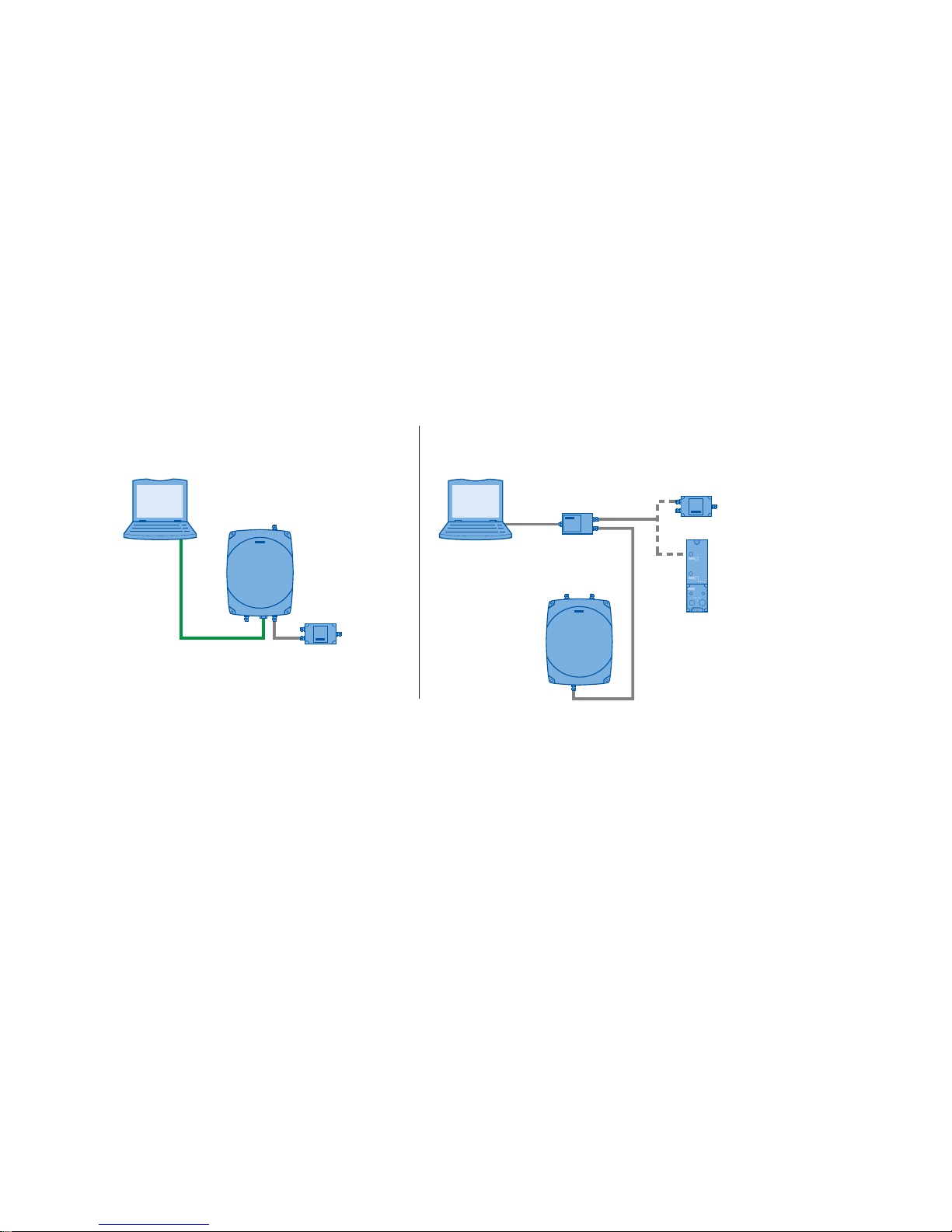
To be able to read out data from readers using the diagnostics tool or to assign parameters
to the reader, you need to connect the reader involved to a PC.
The Ethernet-based readers RF640R/RF670R can be connected quickly and simply to the
PC using a crossover cable or with an Ethernet adapter capable of cross-linking. The serial
readers RF620R/RF630R need to be connected to the PC using the PC adapter that ships
with the product. You will find further information about the PC adapter and connecting the
readers in the following sections.
3*3&
3*3&
3&DGDSWHU
&RQQHFWLRQRI(WKHUQHWEDVHGUHDGHUV &RQQHFWLRQRIVHULDOUHDGHUV
&0
:LGHUDQJHSRZHU
VXSSO\XQLW
:LGHUDQJHSRZHU
VXSSO\XQLW
5)55)5
5)55)5
Figure 3-1 Connecting the reader to a PC
Page 12
Connecting hardware
3.1 The PC adapter for SIMATIC RF-DIAG
SIMATIC RF-DIAG
12 Operating Manual, 09/2012, C79000-G8976-C292-01
3.1 The PC adapter for SIMATIC RF-DIAG
3.1.1 Description
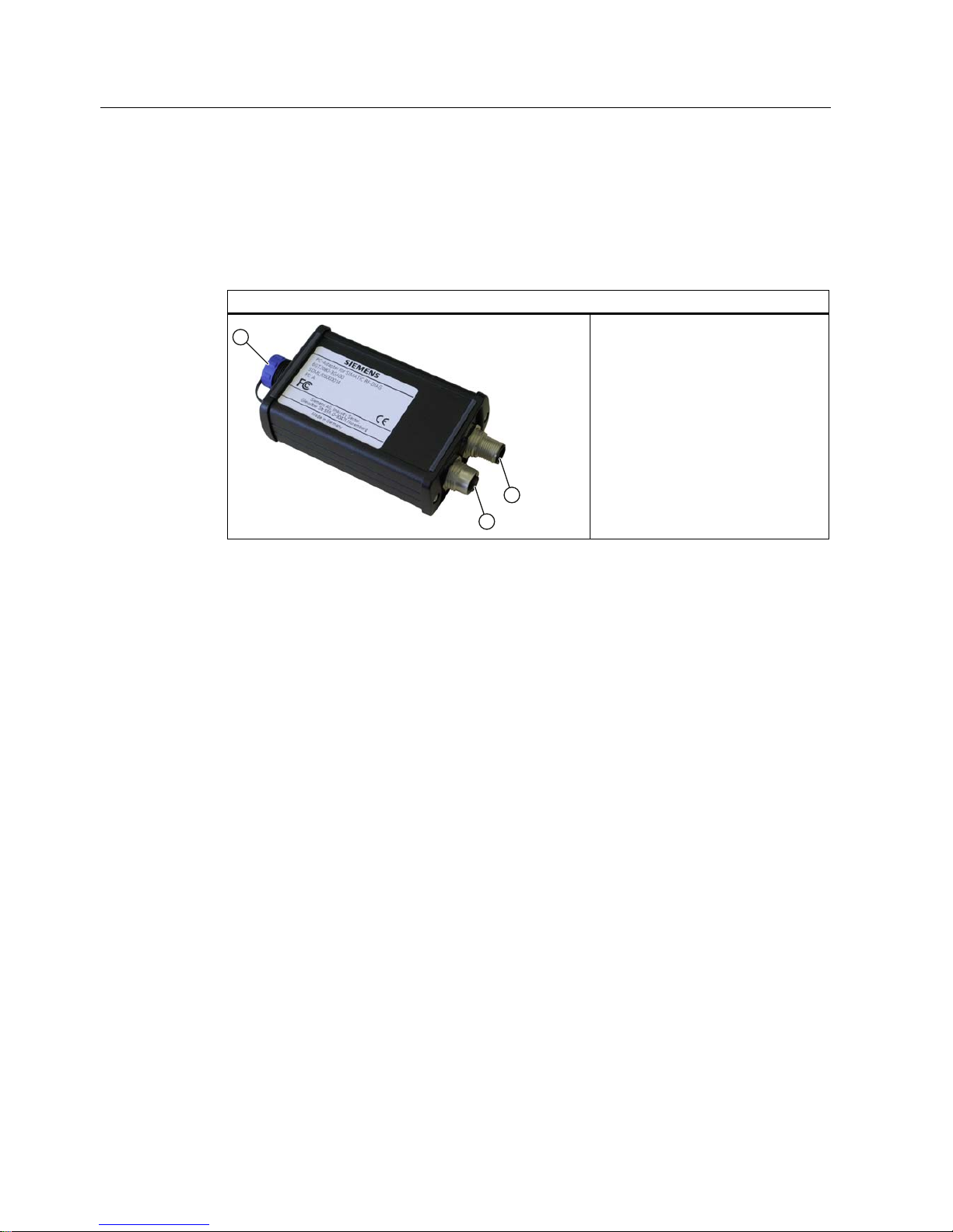
PC adapter for SIMATIC RF-DIAG
① USB interface
② RS-422 – CM / wide-range power
supply unit
③ RS-422 – RF reader
The SIMATIC RF-DIAG product consists of a CD with software and documentation and a
hardware packet. The hardware packet consists of a PC adapter for SIMATIC RF-DIAG, a
USB connecting cable and an RS-422 cable.
The PC adapter for SIMATIC RF-DIAG is a converter from USB to RS-422. Communication
between the PC and reader can be established using the PC adapter.
Characteristics
● RS-422 to USB converter for communication with the RF620R and RF630R
● Dimensions without connecting cables: 101 x 63 x 35 mm
● CE-compliant (EU and UK versions)
● FCC-compliant for use in the USA and Canada
● Mechanically and electrically rugged design
● RS-422 interface
– With 24 VDC / 3 A for CM or wide-range power supply unit
– With 24 VDC / 3 A for reader
● Short-circuit proof
Page 13
Connecting hardware
3.1 The PC adapter for SIMATIC RF-DIAG
SIMATIC RF-DIAG
Operating Manual, 09/2012, C79000-G8976-C292-01
13
Highlights
● Diagnostics via a PC with the reader supplied with power from the system
● IP65 degree of protection
● Can be used in high temperature ranges
● Use in productive operation possible
● Switchover to diagnostics mode "on the fly" (parallel to regular operation)
Note
Protection from environmental influences
The IP65 degree of protection of the PC adapter is only valid if the USB protective cap is
fitted and the corresponding RS-422 cable is connected. During diagnostics, this degree of
protection is not present.
3.1.2 Pin assignment of the RS-422 interface
Pin assignment for connection to the CM or wide-range power supply unit
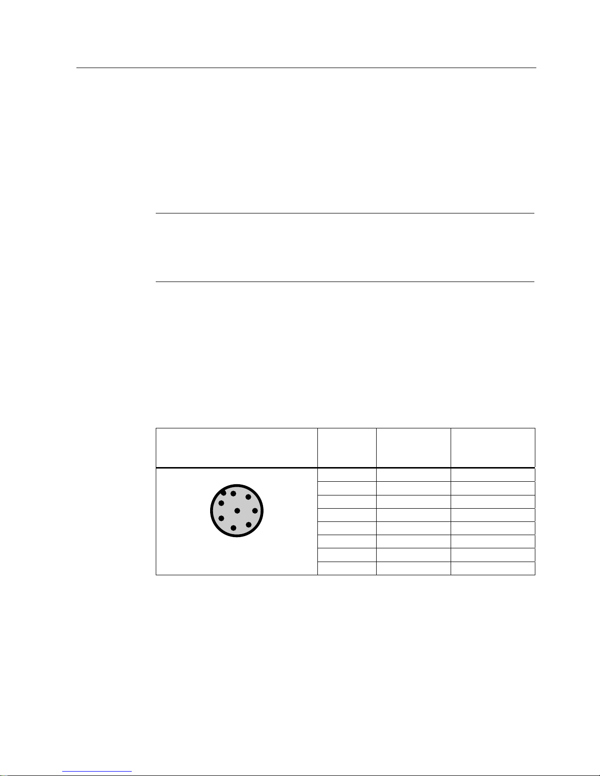
Pin assignment of the connector for PC adapter and CM or wide-range power supply unit
Table 3- 1 RS-422 interface of the PC adapter (male connector)
Pin Pin
Device end 8pin M12
Assignment for
CM
Assignment for
wide-range power
supply unit
1 + 24 V + 24 V
2 - Transmit Free
3 0 V 0 V
4 + Transmit Free
5 + Receive Free
6 - Receive Free
7 Free Free
8 Ground (shield) Ground (shield)
The knurled bolt of the M12 plug does not contact the shield (reader end).
Page 14
Connecting hardware
3.1 The PC adapter for SIMATIC RF-DIAG
SIMATIC RF-DIAG
14 Operating Manual, 09/2012, C79000-G8976-C292-01
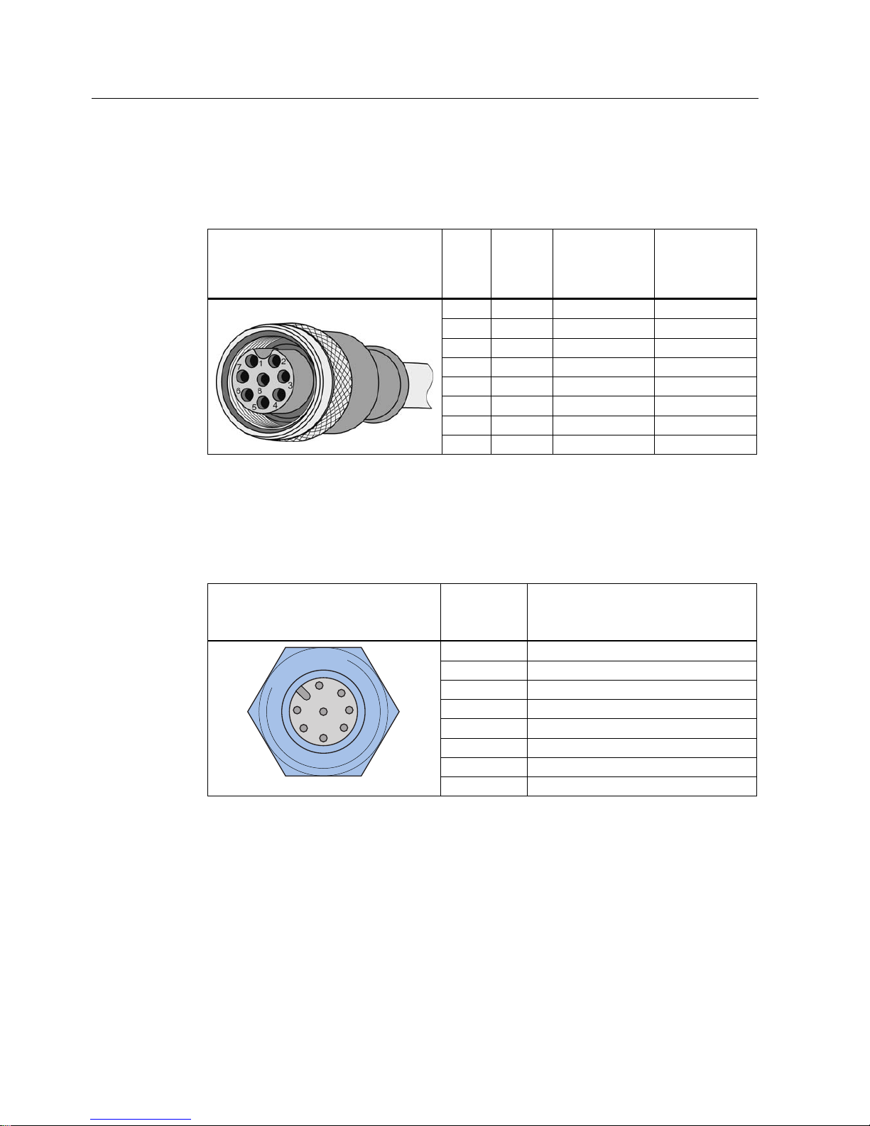
Pin assignment of the connecting cable between PC adapter and CM or wide-range power
supply unit
Table 3- 2 RS-422 connecting cable
View of M12 socket M12
pin
Core
color
Pin assignment
for CM
Pin assignment
for wide-range
power supply
unit
1 White 24 VDC 24 VDC
2 Brown TX neg Not used
3 green GND GND
4 Yellow TX pos Not used
5 gray RX pos Not used
6 pink RX neg Not used
7 Blue Not used Not used
8 Red Ground (shield) Ground (shield)
Pin assignment for connecting to the RF readers
Pin assignment of the connector for PC adapter and UHF reader
Table 3- 3 RS-422 interface of the PC adapter (female connector)
Pin Pin
Device end 8pin M12
Assignment for the RF readers
1 + 24 V
2 - Transmit
3 0 V
4 + Transmit
5 + Receive
6 - Receive
7 Free
8 Ground (shield)
The knurled bolt of the M12 plug does not contact the shield (reader end).
Page 15
Connecting hardware
3.1 The PC adapter for SIMATIC RF-DIAG
SIMATIC RF-DIAG
Operating Manual, 09/2012, C79000-G8976-C292-01
15
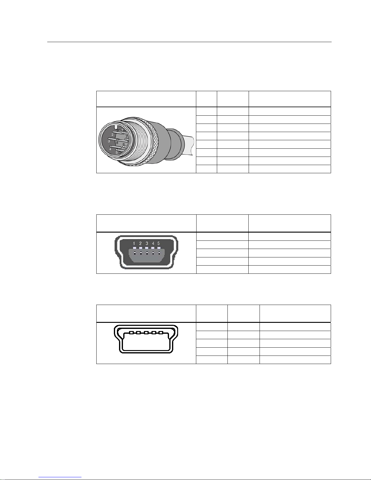
Pin assignment of the connecting cable between PC adapter and UHF reader
Table 3- 4 RS-422 connecting cable
View of M12 plug M12
pin
Wire color Pin assignment
1 White 24 VDC
2 Brown TX neg
3 green GND
4 Yellow TX pos
5 gray RX pos
6 pink RX neg
7 Blue Not used
8 Red Ground (shield)
Pin assignment for connection to the PC
Table 3- 5 USB 2.0 mini-B connector socket of the PC adapter
View of connection socket Pin
Device side
Assignment
1 + 5 V
2 Data 3 Data +
4 ID (not used)
5 GND
Table 3- 6 USB 2.0 mini-B plug of the connecting cable
View of mini-B plug Pin
Device side
Wire color Assignment
1 Red + 5 V
2 White Data 3 green Data +
4 - ID (not used)
5 Black GND
Page 16
Connecting hardware
3.1 The PC adapter for SIMATIC RF-DIAG
SIMATIC RF-DIAG
16 Operating Manual, 09/2012, C79000-G8976-C292-01
3.1.3 Technical specifications
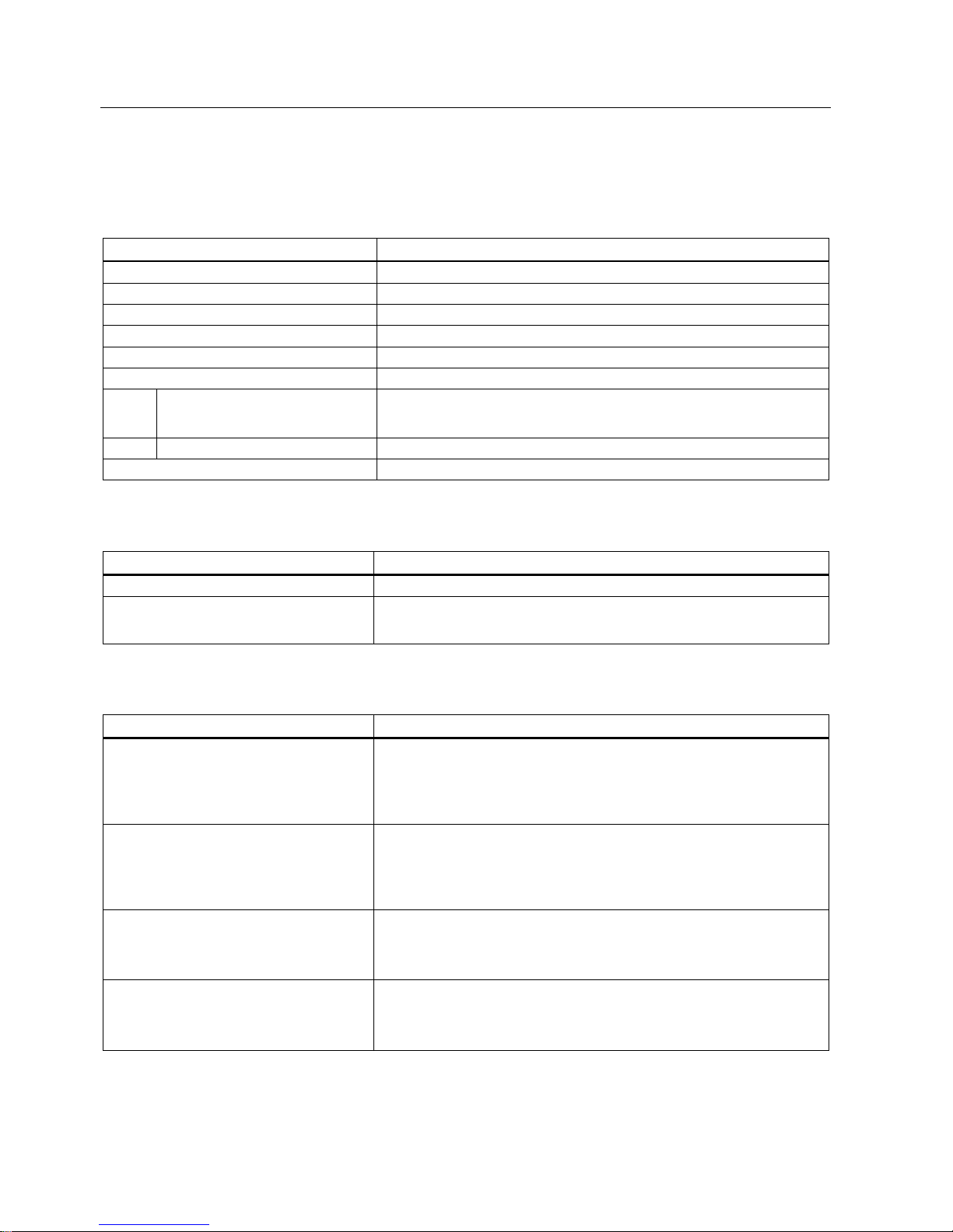
Table 3- 7 Mechanical data
Property Description
Weight 310 g
Dimensions (L x W x H) 101 × 63 × 35 mm
Enclosure material Aluminum (painted)
Housing color Black
Installation No securing aids
Interfaces
RS422
• 1 x pin (8-pin M12, connection to CM/wide-range power supply)
• 1 x socket (8-pin M12, connection to the reader)
USB USB 2.0 Mini-B
MTBF in years 1.1x10³
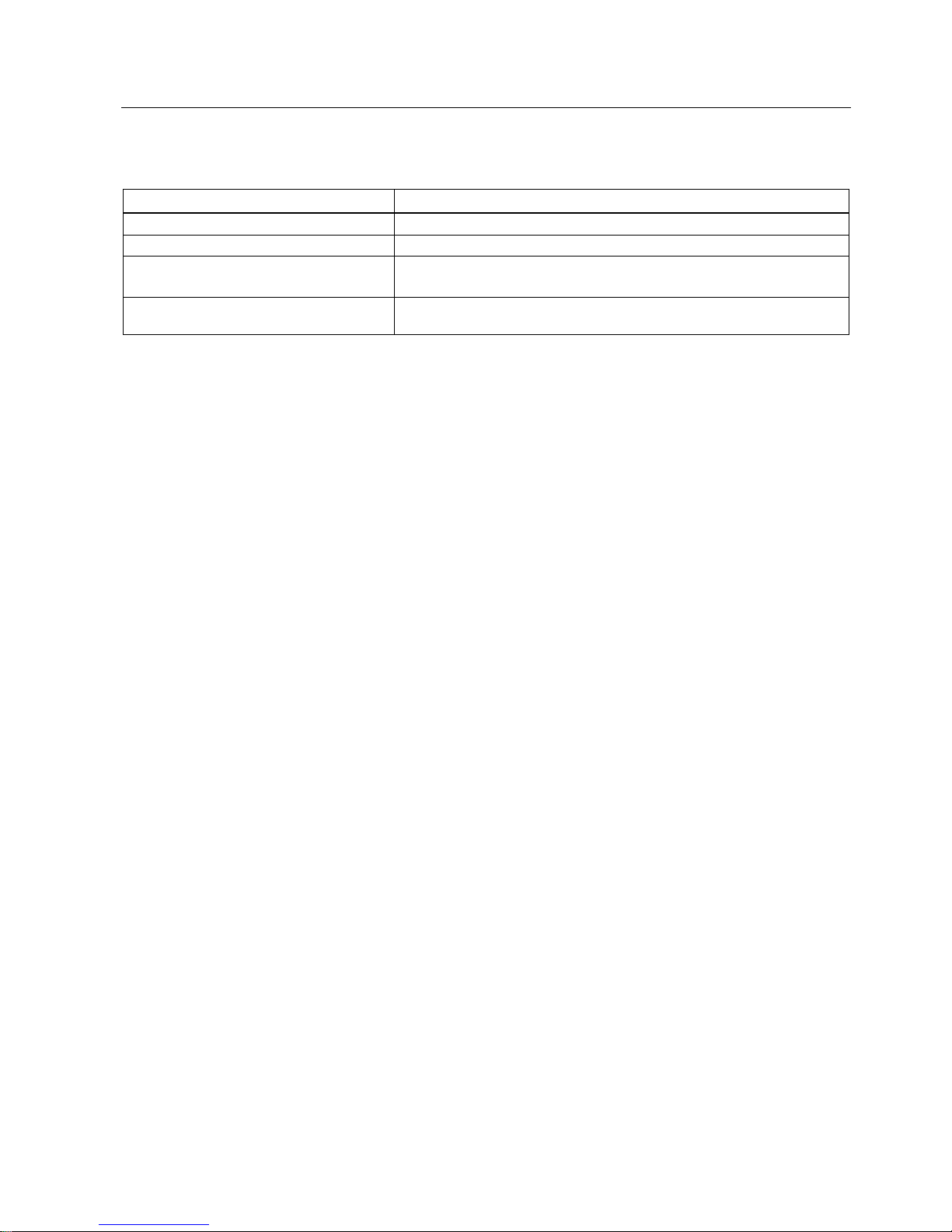
Table 3- 8 Software interfaces
Property Description
Software – RS-422 SIMATIC S7 / TIA
Software – USB
• RF600
• 3964R & RF-DIAG
Table 3- 9 Electrical data
Property Description
Power supply of the PC adapter via USB
(during operation)
• Nominal value
• Permitted range
• 5 V DC
• 4.0 to 5.25 VDC
Power supply of the RF readers via RS-422
• Nominal value
• Permitted range
• 24 VDC
• 20 to 30 VDC
Current consumption
• Connection via USB and RS-422
• No connection via USB
• Via 5 VDC, approx. 30 mA; 24 VDC, approx. 15 mA
• Via 24 VDC, ≤ 5 mA
Transmission rates USB / RS-422
• 19.2 Kbps
• 57.6 Kbps
• 115.2 Kbps
Page 17
Connecting hardware
3.1 The PC adapter for SIMATIC RF-DIAG
SIMATIC RF-DIAG
Operating Manual, 09/2012, C79000-G8976-C292-01
17
Table 3- 10 Ambient conditions
Property Description
Temperature range during operation -25 ℃ to +70 ℃
Temperature range during storage -40 ℃ to +85 ℃
Shock resistant to EN 60068-2-27
Vibration resistant to EN 60068-2-6
50 g, 1)
20 g,
1)
Degree of protection in accordance with
EN 60529
IP65 2)
1)
The values for shock and vibration are maximum values and must not be applied continuously nor when the USB plug is
plugged in.
2)
Only when the USB protective cap is fitted and the corresponding RS-422 cables are connected.
Page 18
Connecting hardware
3.1 The PC adapter for SIMATIC RF-DIAG
SIMATIC RF-DIAG
18 Operating Manual, 09/2012, C79000-G8976-C292-01
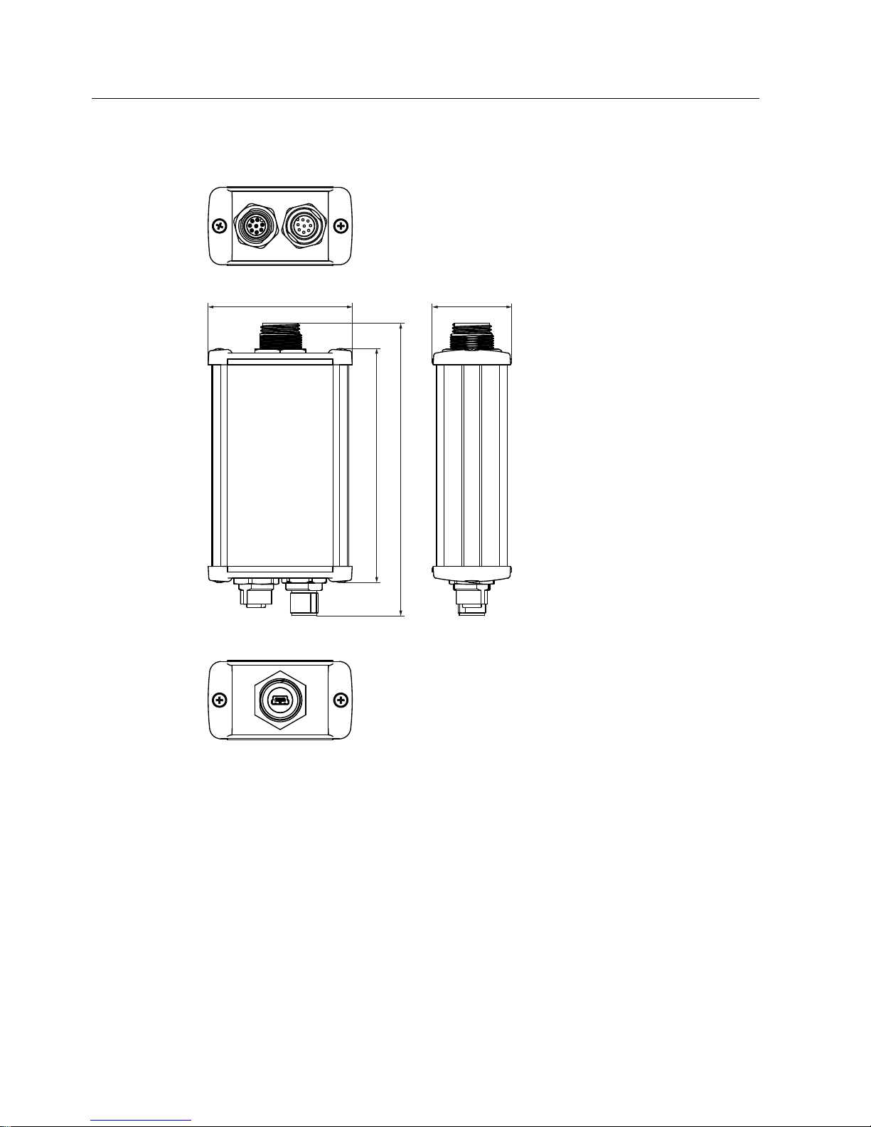
3.1.4 Dimension drawing
Figure 3-2 Dimension drawing of the PC adapter for SIMATIC RF-DIAG (all dimensions in mm)
When the USB protective cap is screwed on, the length of the adapter is 134 mm. The
tolerances are +/- 1 mm.
Page 19
Connecting hardware
3.2 Connecting the hardware
SIMATIC RF-DIAG
Operating Manual, 09/2012, C79000-G8976-C292-01
19
3.1.5 Certificates and approvals
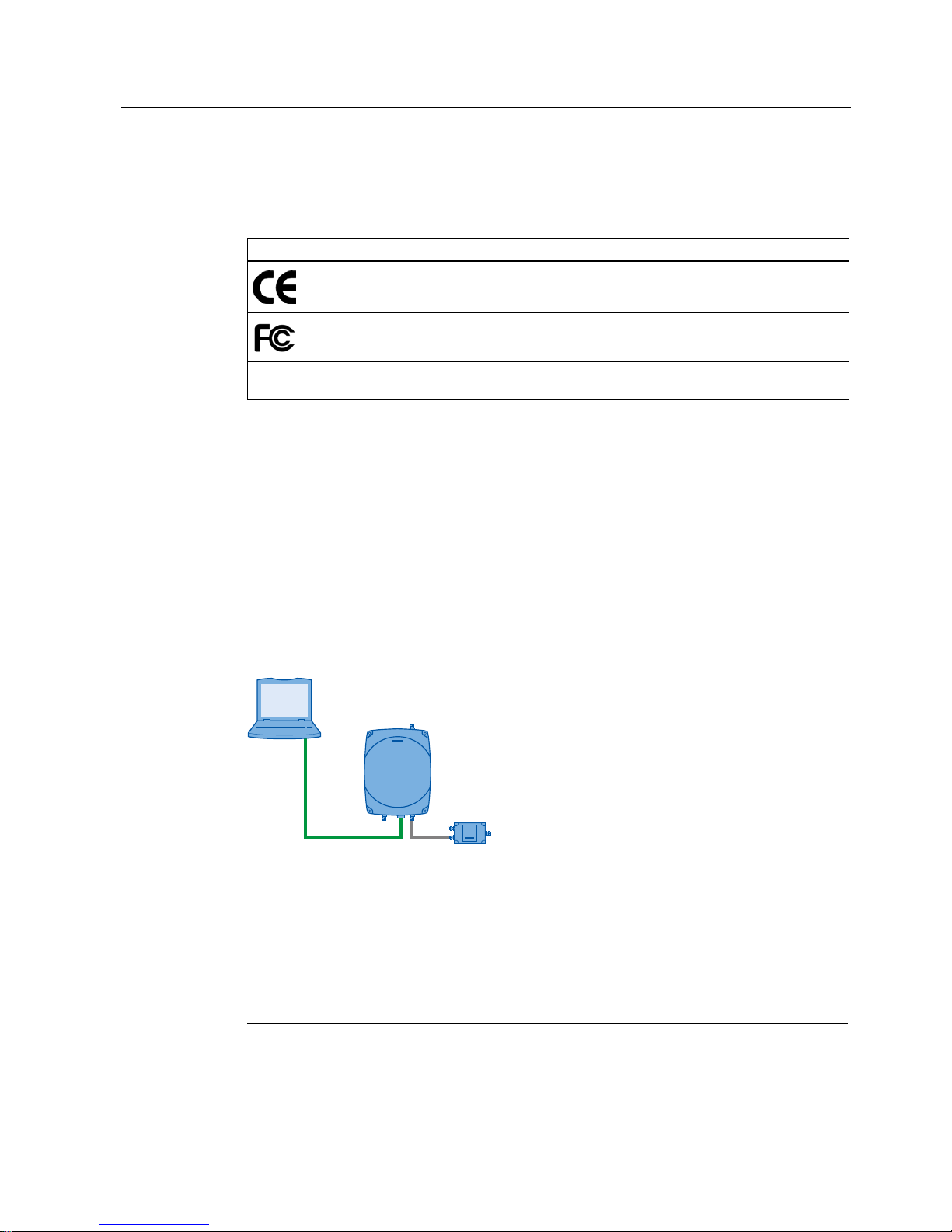
Table 3- 11 Certificates and approvals for the PC adapter
Certificate Description
CE approval complying with 2004/108/EC EMC
FCC Rules, Part 15, Subpart B, Sections 15.107 and 15.109
Industry Canada Radio
Standards Specifications
CAN/CSA-CISPR 22-10 - Information technology equipment – Radio
disturbance characteristics – Limits and methods of measurement
3.2 Connecting the hardware
3.2.1 Connecting an Ethernet-based reader
Connecting an Ethernet-based reader in an isolated test environment
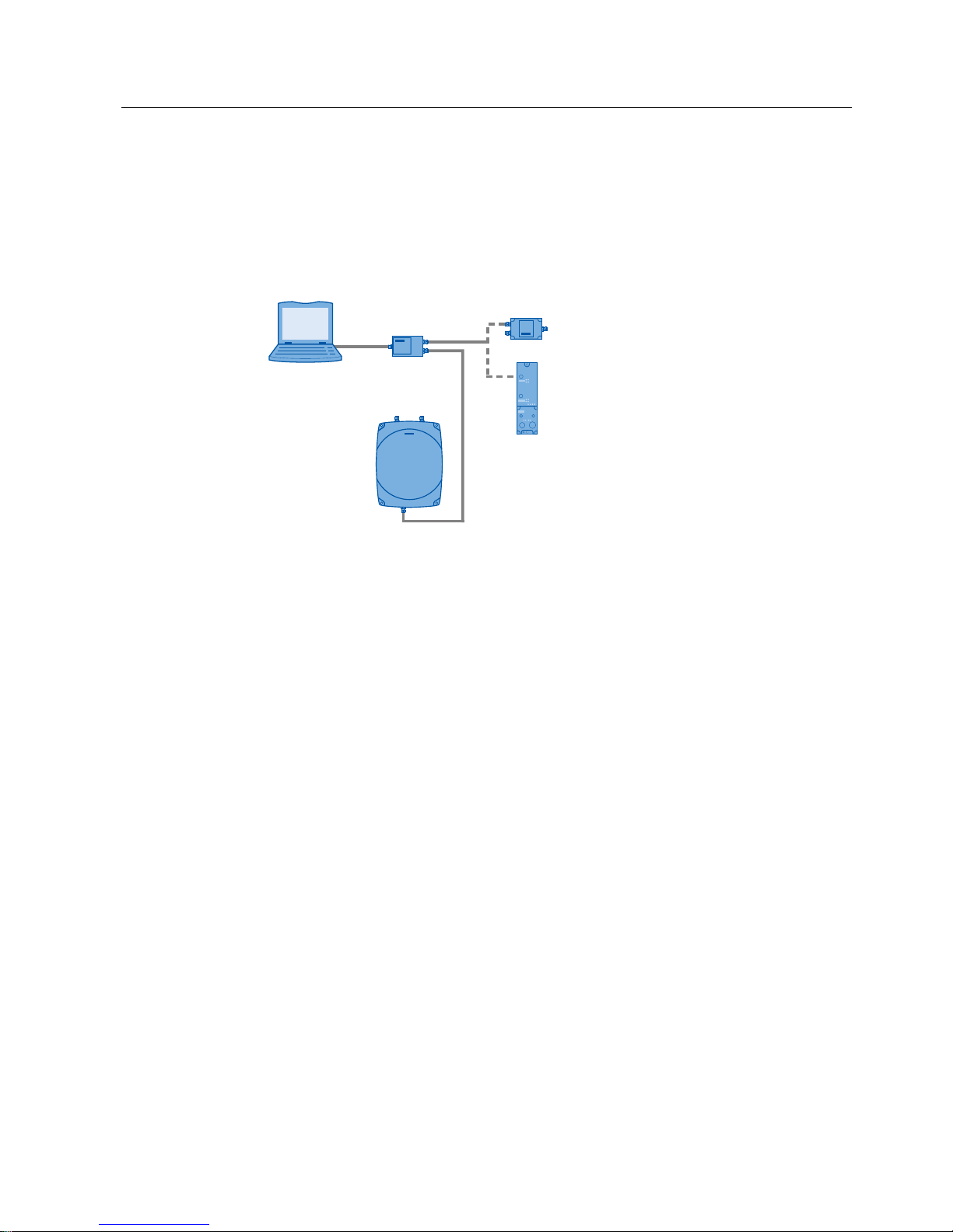
To set up or to diagnose an Ethernet-based reader RF640R/RF670R, you can connect the
reader to the PC using a crossover cable or an Ethernet adapter capable of cross-linking.
3*3&
:LGHUDQJHSRZHUVXSSO\XQLW
5)55)5
Figure 3-3 Connecting Ethernet-based readers to a PC
Note
Reader parameter assignment with RF-MANAGER Basic
Remember that you assign parameters and correct the readers using the RF-MANAGER
Basic. SIMATIC RF-DIAG is used only to check the current settings.
Note that the reader cannot communicate with more than one software tool at any one time.
You will find further information on connecting up and assigning parameters for an Ethernetbased reader in the manual "RF-MANAGER Basic".
Page 20

Connecting hardware
3.2 Connecting the hardware
SIMATIC RF-DIAG
20 Operating Manual, 09/2012, C79000-G8976-C292-01
You require the following:
● Ethernet cable
● Adapter cable for wide-range power supply unit
● Wide-range power supply unit
Follow the steps below to connect an Ethernet-based reader to a PC:
1. Connect the PC to the reader using a crossover cable.
2. Start the SIMATIC RF-DIAG diagnostics tool and establish the connection between the
PC and reader using the software user interface as described in the sections "Starting the
softwa
re (Page 25) and "Operating the software (Page 29)".
Page 21
Connecting hardware
3.2 Connecting the hardware
SIMATIC RF-DIAG
Operating Manual, 09/2012, C79000-G8976-C292-01
21
3.2.2 Connecting a serial reader
The serial readers need to be connected to the PC using the PC adapter. The following
scenarios are possible:
● Diagnostics of a serial reader in an isolated test environment
● Diagnostics of a serial reader in industrial applications
3*3&
3&DGDSWHU
:LGHUDQJHSRZHUVXSSO\XQLW
&0
5)55)5
Figure 3-4 Connecting serial readers to a PC
Diagnostics of a serial reader in an isolated test environment:
To set up an RF620R//RF630R serial reader or to run diagnostics on it, you require the
supplied PC adapter for SIMATIC RF-DIAG. To run diagnostics in an isolated test
environment, you require neither a master module nor a communications module.
You require the following:
● Wide-range power supply unit
● Adapter cable for wide-range power supply unit
● RS-422 cable (ships with product)
● USB cable (ships with product)
Follow the steps below to operate a serial reader from a PC:
1. Connect the wide-range power supply unit to the interface with an RS-422 cable.
The connected wide-range power supply unit supplies the reader with power.
2. Connect the reader to the interface with an RS-422 cable.
3. Connect the PC to the USB interface using the USB connecting cable.
4. Start the SIMATIC RF-DIAG diagnostics tool and establish the connection between the
PC and reader using the software user interface.
Page 22

Connecting hardware
3.2 Connecting the hardware
SIMATIC RF-DIAG
22 Operating Manual, 09/2012, C79000-G8976-C292-01
Diagnostics of a serial reader in industrial applications:
When using a serial reader in an industrial environment, the reader is operated using CMs
and a master module. To set up an RF620R//RF630R serial reader or to run diagnostics on
it, you also require the PC adapter for SIMATIC RF-DIAG.
To run diagnostics, you need to disconnect the reader from the CM and connect both
devices to the PC adapter via the RS-422 interface. Communication between the reader and
CM is via the PC adapter.
To run diagnostics, you now need to connect the PC to the reader via the USB interface of
the PC adapter. As soon as the PC has been connected to the PC adapter, communication
between the CM and reader is interrupted. You can now read out the data or adapt
parameters using the PC. If you disconnect the PC and PC adapter in the software user
interface, the reader is automatically restarted. Then disconnect the USB cable to prevent a
restart of the reader in diagnostics mode and to restore the communications connection
between reader and CM. Data that has not been saved is lost. During this procedure, the
power supply is always maintained.
Note
Sequence when disconnecting
Always disconnect the PC and PC adapter first using the software user interface before you
unplug the USB cable.
You require the following:
● Operational CM connected using a suitable connecting cable between the CM and reader
● 2 x RS-422 cable (one cable ships with the product, use a second cable from the plant)
● USB cable (ships with product)
Follow the steps below to operate a serial reader in an industrial environment:
1. Connect the CM to the interface with an RS-422 cable.
The reader is supplied with power via the connected CM.
2. Connect the reader to the interface with an RS-422 cable.
3. Connect the PC to the USB interface using the USB connecting cable.
As soon as you connect the PC, the connection between the CM and reader is
interrupted. Communication with the connected PC is now via the USB interface.
4. Start the SIMATIC RF-DIAG diagnostics tool and establish the connection between the
PC and reader using the software user interface.
Page 23

SIMATIC RF-DIAG
Operating Manual, 09/2012, C79000-G8976-C292-01
23
Software installation
4
4.1 Installing the software
To use the SIMATIC RF-DIAG diagnostics tool, you do not need to perform any installation.
Follow the steps below to copy the diagnostics tool to your PC:
1. Insert the supplied CD in your CD drive.
2. Right-click on the "SIMATIC RF-DIAG" folder on the CD and select the "Copy" command
in the shortcut menu.
3. Select the folder on your PC to which you want to copy the diagnostics tool.
4. Right-click on the folder and select the "Paste" command in the shortcut menu.
Note
Installing .NET Framework
If an error message appears when you start the diagnostics tool SIMATIC RF-DIAG, this
indicates that the required version of .NET Framework is not yet on your system.
The required version of .NET Framework is available on the CD in the "DotNET Framework
2.0" folder.
Run both setups "NetFx20SP2_x86.exe" and then "NDP20SP2-KB958481-x86.exe" to install
the required components.
4.2 Installation and use of the USB driver
To operate the SIMATIC RF-DIAG application with a serial reader (RF620R/RF630R), the
appropriate USB driver "Silicon Labs CP210x USB to UART Bridge" Version 6.5.3.0 is
required for communication via the PC adapter for SIMATIC RF-DIAG. The following steps
are described based on the "Windows XP" operating system.
Page 24

Software installation
4.2 Installation and use of the USB driver
SIMATIC RF-DIAG
24 Operating Manual, 09/2012, C79000-G8976-C292-01
A. Check for and uninstall older variants of the USB driver "Silicon Labs CP210x USB to
UART Bridge" version 6.5.3.0
1. Open "Computer Management " with "Start > Settings > Control Panel > Administrative
Tools".
2. Select "Device Manager" and open the subfolder "Ports (COM & LPT)".
If the USB driver "Silicon Labs CP210x USB to UART Bridge" was installed previously,
you will find the following as one of the entries:
"Silicon Labs CP210x USB to UART Bridge (COM<x >)" (e.g. "Silicon Labs CP210x USB
to UART Bridge (COM5)").
If there is no"Silicon Labs CP210x USB to UART Bridge" entry in the "Ports (COM &
LPT)" subfolder, you can cancel the steps already taken in the open dialog boxes and
start installation of the USB driver.
3. Select the entry with the right mouse button and then select "Properties" in the shortcut
menu.
In the "Driver" tab of the dialog box that now opens, you will find the "Driver Version"
entry.
4. If the driver version is lower than 6.5.3, click "Cancel".
5. Uninstall the driver by selecting the USB driver with the right mouse button and selecting
"Uninstall" in the shortcut menu.
6. Follow the instructions of the wizard.
B. Installation of the USB driver for the PC adapter for SIMATIC RF-DIAG
1. Install the correct variant (32/64-bit) of the USB driver using the setup
"CP210xVCPInstaller.exe" in "<CD>\SiLabs\MCU\CP210x\Windows_XP_S2K3_Vista_7".
2. Following installation, insert the USB cable that is already connected to the PC adapter
into the PC.
At the bottom right of the screen, you will see a message that a new device has been
detected and the initialization of the PC adapter is completed.
3. The new device appears in the Device Manager as "Silicon Labs CP210x USB to UART
Bridge".
To identify the COM port that needs to be set in the SIMATIC RF-DIAG application for serial
readers, follow the steps below:
C. Selecting the COM port using SIMATIC RF-DIAG
1. Open "Computer Management " with "Start > Settings > Control Panel > Administrative
Tools".
2. Select "Device Manager" and open the subfolder "Ports (COM & LPT)".
3. If the USB driver of the PC adapter for SIMATIC RF-DIAG was correctly installed earlier,
you
will find the following as one of the entries:
"Silicon Labs CP210x USB to UART Bridge (COM<x >)" (e.g. "Silicon Labs CP210x USB
to UART Bridge (COM5)").
This means that you select COM<x> from the drop-down list in the SIMATIC RF-DIAG
application as the port (in the example above "COM5").
Page 25
Software installation
4.3 Starting the software
SIMATIC RF-DIAG
Operating Manual, 09/2012, C79000-G8976-C292-01
25
4.3 Starting the software
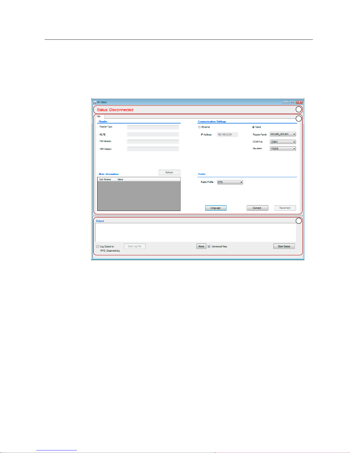
Once you have copied the diagnostics tool, you can start SIMATIC RF-DIAG by doubleclicking on the "SIMATIC_RF-DIAG.exe" file. After starting the software, the user interface of
the diagnostics tool appears:
The 3 areas of the software user interface
① Status area
② Reader-specific functionalities
③ Protocol area
Figure 4-1 User interface of the SIMATIC RF-DIAG software
Page 26
Software installation
4.3 Starting the software
SIMATIC RF-DIAG
26 Operating Manual, 09/2012, C79000-G8976-C292-01
Status area ①
The status area shows which reader type is currently connected to the PC as well as the
current status of the connection.
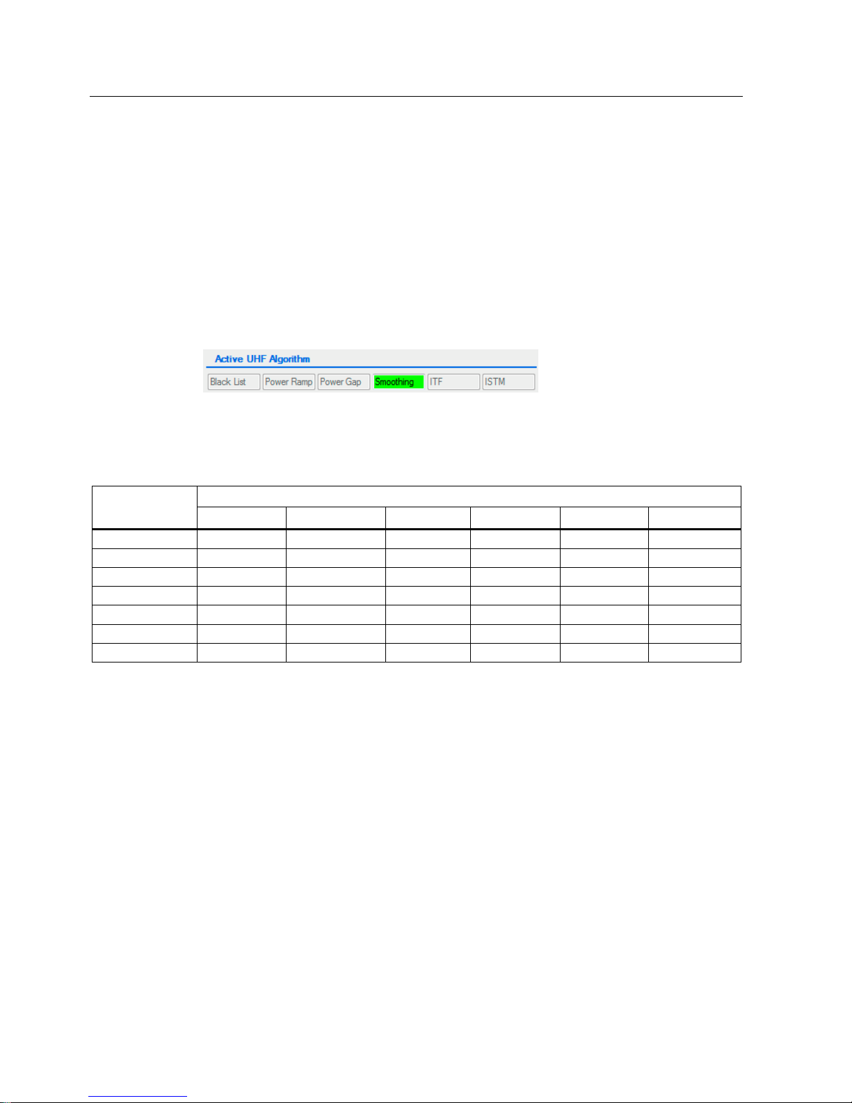
Display of the active UHF algorithms:
only with RF620R / RF630R
As soon as the connection is established to a serial reader, the possible UHF algorithms are
also displayed. The UHF algorithms that were activated are highlighted on a green
background.
Figure 4-2 Display of the active UHF algorithms
The following table shows the tabs of the software user interface that are affected by the
active UHF algorithms:
Active UHF algorithm Tab
Black List Power Ramp Power Gap Smoothing ITF ISTM
Info - - - - - Tag Data X - - - - RSSI X - - - - Power Ramp X X - - - Tag list X X X X X X
VSWR - - - - - Firmware update - - - - - -
Reader-specific functionalities ②
After starting the program only the "Info" tab is displayed. This tab is always displayed
regardless of the connection status and the reader type. It serves as the central starting point
for establishing a connection to the reader.
Various tabs are displayed depending on the reader you connect to. The "Reader-specific
functionalities" area depends on the particular tab and displays reader-specific functions.
If you have established the connection to a reader, various functions of the diagnostics tool
are displayed in tabs depending on the connected reader.
You will find the list of all tabs and a detailed description of the functions in the section
"Operating the software (Page 29)".
Page 27

Software installation
4.3 Starting the software
SIMATIC RF-DIAG
Operating Manual, 09/2012, C79000-G8976-C292-01
27
Logging area ③
This part of the application provides a logging function with which all actions performed,
events and error messages are logged. You will find more detailed information on the
logging area in the section "The log area (Page 30)".
Page 28

Software installation
4.3 Starting the software
SIMATIC RF-DIAG
28 Operating Manual, 09/2012, C79000-G8976-C292-01
Page 29

SIMATIC RF-DIAG
Operating Manual, 09/2012, C79000-G8976-C292-01
29
Operating the software
5
Note
Entry of incorrect values
Newly entered values are checked only when they are changed or written to the reader. If
you enter incorrect or invalid values in input boxes, these values are not transferred to the
reader when you attempt to make changes or write to the reader. Following attempted
changes/writing, these invalid values are highlighted in the user interface in orange.
Note
Display of changed values
Changed values that have not yet been transferred to the reader are shown in green.
Page 30

Operating the software
5.1 The log area
SIMATIC RF-DIAG
30 Operating Manual, 09/2012, C79000-G8976-C292-01
5.1 The log area
Setting options for the log area
The log area is included in all tabs. All the actions taken are logged in the output window of
the logging area. The output is stored in a ring buffer. When the buffer is full, the oldest
entries are overwritten by the newer entries.
You can save the displayed entries in a log file ("RFID_Diagnosis.log"). Apart from the
information displayed in the user interface, all communication from and to the reader is also
logged. This allows a more thorough analysis later if problems occur. The log file is located
in the same directory as the executable program "SIMATIC_RF-DIAG.exe".
The maximum size of the log file is only limited by the file system and the space on the hard
disk of the computer you are using.
With the "About" button, you can display the version of the software.
To display all tabs of the diagnostics tool, you need to select the "Advanced View" check
box. In the default setting, the only tabs displayed are those with which you can only read out
data. By selecting the "Advanced View" check box, you also see the tabs with which you can
change parameters. You will find a list of the tabs in the following section.
Once you have selected the check box, you need to enter the password and confirm with
"OK". The default password set in the factory is "1234". Click the "Change" button to change
the password.
Both the content of the display window as well as the log file can be emptied separately
using the "Clear Output" or "Clear Log File" buttons.
Note
Forgotten password
If the password is forgotten, the software needs to be reinstalled.
Page 31
Operating the software
5.2 Tab overview
SIMATIC RF-DIAG
Operating Manual, 09/2012, C79000-G8976-C292-01
31
5.2 Tab overview
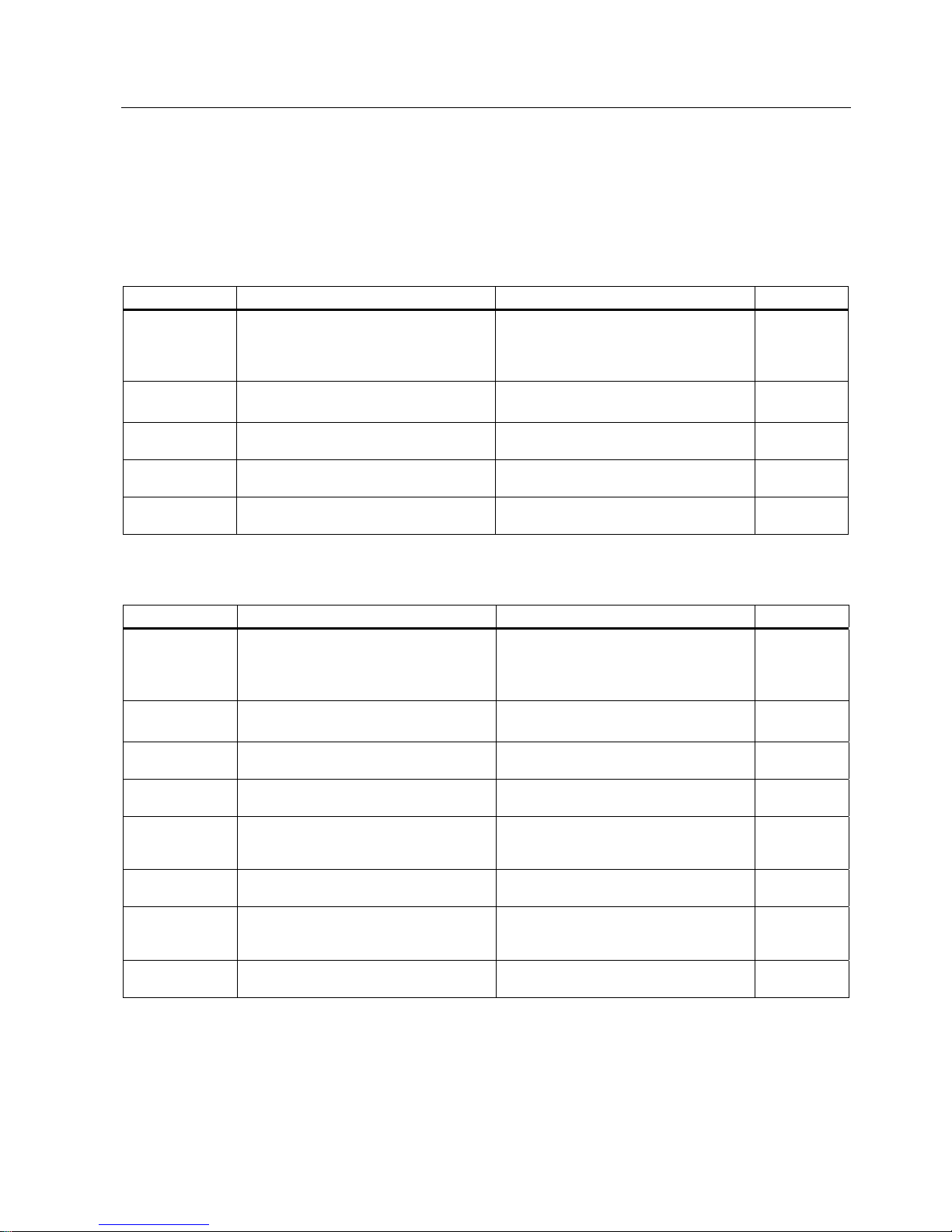
After successful establishment of a connection to the reader, the following tabs are available
depending on the connected reader type and the firmware version:
Table 5- 1 The tabs of the Ethernet-based readers RF640R/RF670R
Tab Functionality Note/uses Adv. View
Info
• Connection establishment to reader
• Display of reader-specific information
• Change language
Always visible
Precise indication of which reader type is
connected.
Tag Data Read and write functions for the memory
areas of a transponder.
Test of the functionality of the reader
Check of transponder data
☑
Tag Events Visualization of the transponder events
sent by the reader.
Test of the functionality of the reader
IO Setting outputs and visualization of the
current statuses of the inputs.
Test of the functionality of the reader
RSSI Display of the RSSI values of the read
transponders
Optimization of the antenna alignment
Table 5- 2 The tabs of the serial readers RF620R/RF630R
Tab Functionality Note/uses Adv. View
Info
• Connection establishment to reader
• Display of reader-specific information
• Change language
Always visible. Precise indication of which
reader type is connected.
Tag Data Read and write functions for the memory
areas of a transponder.
Test of the functionality of the reader
Check of transponder data
☑
RSSI Display of the RSSI values of the read
transponders
Optimization of the antenna alignment
Power Ramp
(as of V2.0*)
Visualization of the power set by the
reader per read cycle
Setting the optimum power ramp values. ☑
Tag List
(as of V2.0*)
Display of the RSSI values read over time
and the read power used for them by the
reader.
Check of the effectiveness of the set UHF
features.
☑
Parameter
(as of V2.0*)
Boxes for setting the selected features Setting of all UHF features ☑
VSWR Display of the VSWR value (voltage
standing wave ratio) of the connected
antennas.
Read out of the quality characteristics of
the air interface
☑
Firmware-Update
(as of V1.04*)
Updating the firmware -
*)Firmware version of the reader
Page 32
Operating the software
5.3 The tabs of the RF640R/RF670R readers
SIMATIC RF-DIAG
32 Operating Manual, 09/2012, C79000-G8976-C292-01
5.3 The tabs of the RF640R/RF670R readers
Note
Configuration of the RF640R/RF670R readers is possible only using the RF-MANAGER
Basic
If an RF640R/RF670R reader is connected, the data sources can only be configured with the
RF-MANAGER Basic. The SIMATIC RF-DIAG diagnostics tool only accesses the
configuration loaded on the reader.
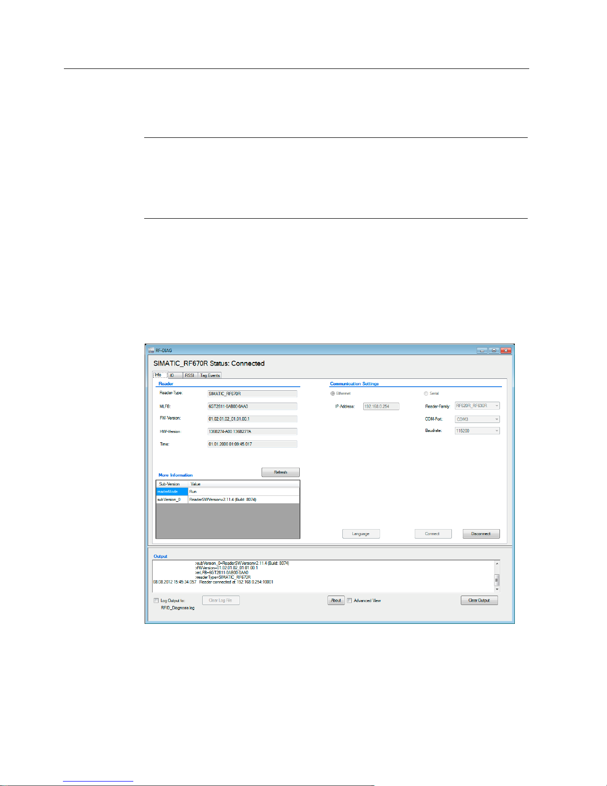
5.3.1 The "Info" tab
With the functions on the "Info" tab, you can establish the connection to the reader. This tab
is always displayed regardless of the connected reader type or the current connection status.
Following successful connection establishment to a reader, important basic information of
the reader is displayed.
Figure 5-1 The "Info" tab following successful connection establishment to an RF670R
Page 33

Operating the software
5.3 The tabs of the RF640R/RF670R readers
SIMATIC RF-DIAG
Operating Manual, 09/2012, C79000-G8976-C292-01
33
Establishing a connection to Ethernet-based readers
To establish a connection to an Ethernet-based reader, follow the steps below:
1. In the "Communication Settings" area, select "Ethernet".
2. Enter the IP address of the reader currently connected to the PC in the "IP-Address" input
box.
To be able to establish the connection to the reader, this address must be known. Each
reader is assigned the default IP address 192.168.0.254 in the factory.
Note
Reading out and changing the IP address of the reader
You can only read out or change the IP address of a reader using the RF-MANAGER
Basic.
3. Click the "Connect" button.
Reaction: The connection to the reader is established. The basic information of the reader is
displayed in the "Reader" area.
Changing the language
In the "Info" tab, you can change the language of the software user interface. Click the
"Language" button to change the software user interface to German or English.
Page 34
Operating the software
5.3 The tabs of the RF640R/RF670R readers
SIMATIC RF-DIAG
34 Operating Manual, 09/2012, C79000-G8976-C292-01
5.3.2 The "Tag Data" tab
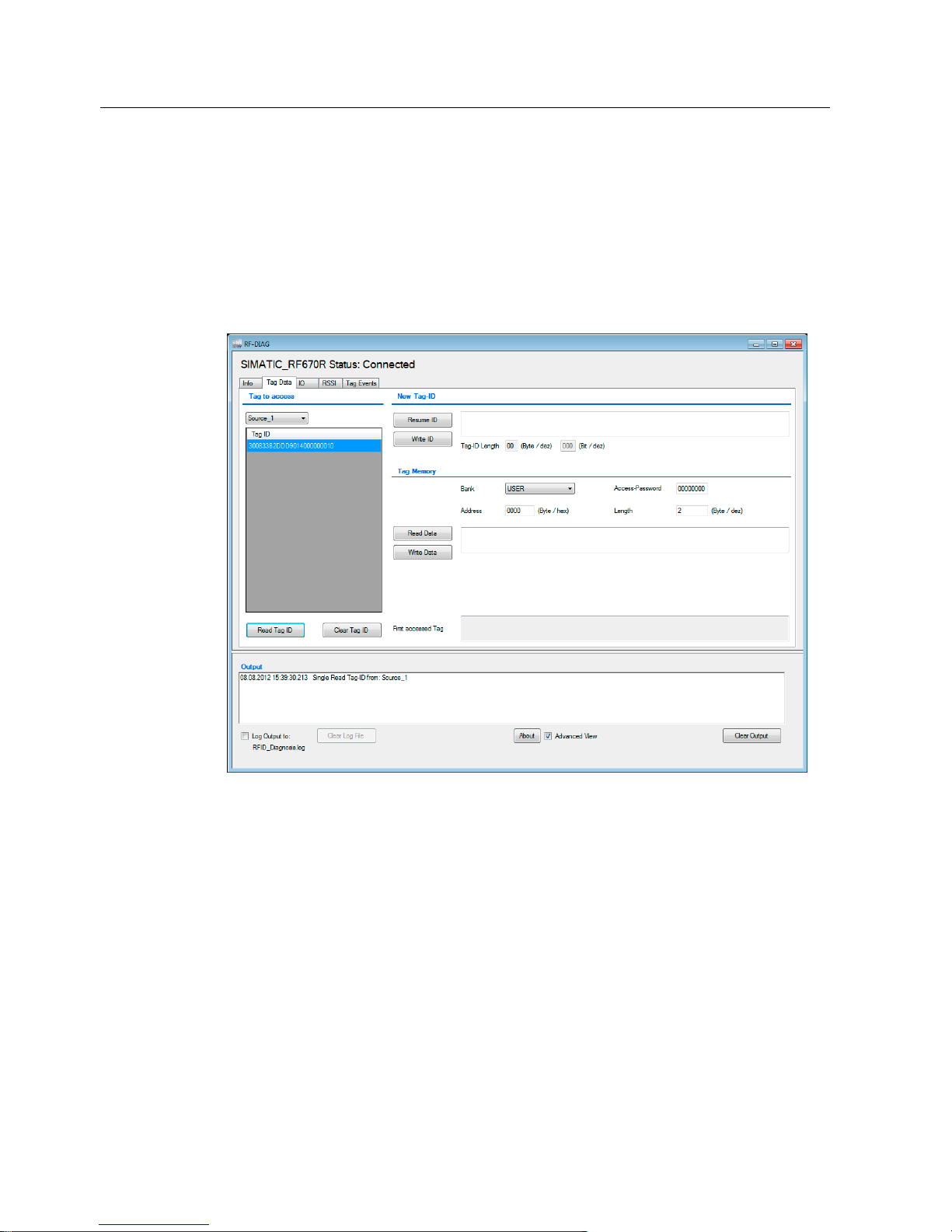
The "Tag Data" tab is displayed only in the advanced view.
Using the "Tag Data" tab, you can verify the transponder data and the basic function of a
reading point quickly and simply. You can read out any data from the transponder or write to
the transponder. When writing to the transponder, you can address all memory areas of the
transponder. With a single command, a maximum of 64 bytes can be read or written.
You can also change the EPC-ID of the transponder.
Figure 5-2 The "Tag Data" tab
Selecting transponders
In the drop-down list of the "Tag to access" area, you can choose the data source via which
the reader will establish the connection to the transponder.
The "Tag ID" list contains all the transponders in the antenna field. You can update the list
with the "Read Tag ID" button. From this list, select the transponder for which you want to
use write or read operations.
Page 35

Operating the software
5.3 The tabs of the RF640R/RF670R readers
SIMATIC RF-DIAG
Operating Manual, 09/2012, C79000-G8976-C292-01
35
Assigning a new tag ID
To assign a new tag ID to a transponder, follow the steps below:
1. Select the required transponder in the "Tag ID" list.
2. In the "New Tag-ID" area, click the "Resume ID" button to accept the current tag ID of the
transponder.
Reaction: The ID of the transponder is displayed as a hexadecimal character string in the
input box.
3. Adapt the tag ID displayed in the input field as required.
The tag ID length to be written is decided by the number of characters and specified in
bytes or bits in two output boxes.
4. Click the "Write ID" button to transfer the new ID to the transponder.
Reaction: The tag ID is written to the transponder.
Note
Error message "Weak Power"
If the error message "Weak Power" appears after writing the tag ID, it is possible that the
new tag ID of the transponder was not overwritten. In this case read out the tag ID again
and, if necessary repeat the write function.
Reading/writing tag data
In the "Tag Memory" area, you can address all memory areas of an ISO 18000-6C
transponder. You can read/write specific data using the "Bank" drop-down list and the two
input boxes "Address" and "Length". To read/write a protected transponder, you will need to
specify the "Access Password" of the transponder.
Click the "Read Data" button to read out the data of the transponder. The data read out is
displayed in the input box as a hexadecimal character string. With the "Write Data" button,
you can write the data in the input box to the transponder.
Note
"Address" input box
In the "Address" input box, you set the address offset (in bytes) of the selected memory bank
(EPC, USER, RESERVED, TID). The meaning of the bytes for each memory bank is
according to ISO 18000-6C.
Note
"Tag to access" list empty or deleted
If the "Tag to access" list is empty or has been deleted, read/write commands then apply to
all transponders in the input box.
Page 36
Operating the software
5.3 The tabs of the RF640R/RF670R readers
SIMATIC RF-DIAG
36 Operating Manual, 09/2012, C79000-G8976-C292-01
Note
"First accessed Tag"
The first transponder to be processed is always displayed. If more than one transponder was
processed in the input box, the list of the EPC IDs of all processed transponders can be
seen in "Output". If there is only one tag that was processed in the input box, this is
displayed.
5.3.3 The "IO" tab
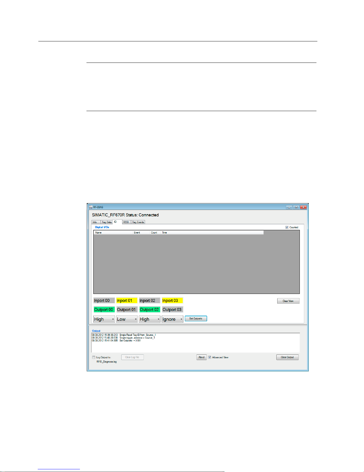
Using the "IO" tab (Inport/Outport), you can read out the inputs and outputs of the connected
readers. In this tab, you can also set specific outputs.
The inputs/outputs of the readers can only be read out synchronously. The reader can also
send IO events for changes at its inputs/outputs. IO events are, however, only sent by the
reader if the reader was suitably configured.
Figure 5-3 The "IO" tab
Page 37

Operating the software
5.3 The tabs of the RF640R/RF670R readers
SIMATIC RF-DIAG
Operating Manual, 09/2012, C79000-G8976-C292-01
37
Displaying the IO events
As soon as you open the "IO" tab, the diagnostics tool starts to record all events (state
changes) of the inputs/outputs (IO events). The detected IO events are displayed in the form
of a table. IO events are, however, only sent by the reader if the reader was suitably
configured. With the default setting, no IO events are sent.
With the "Counted" check box, you can change the table mode to display a compact table.
Note
Enabling or disabling "Counted"
When you enable or disable "Counted", the displayed list is deleted and the displayed events
re-initialized.
The two table modes:
● Counted (default)
Compact overview - recommended if large numbers of IO events are involved. In this
mode only one row of the table is used per input/output and possible event (High, Low). If
an event is repeated on a transponder, only the existing row is updated. Multiple
occurrences of the same event are indicated in the "Count" column. In this mode, it is
easy to recognize how often the state of an input/output has changed.
● Time
Detailed overview - each event is displayed in a separate row. This makes the
chronological sequence of the IO events clear.
Table 5- 3 Displayed properties of the inputs/outputs
Property Description
Name Name of IO port.
Event Type of the event.
The level (High, Low) at which the input/output changed.
Count Number of identical events of this input/output.
Time Time stamp when the event was sent.
Setting the outputs
The digital inputs/outputs are displayed below the table. If an input is occupied, this is
highlighted with a yellow background. To set the outputs again, select the required status
from the drop-down lists and activate this using the "Set Outports" button. Active outputs are
highlighted in green. Changes to the outputs are documented in the logging area (X = no
change, 0 = Low, 1 = High).
Remains: Output is not changed.
Off: Output is changed to "Low" state.
On: Output is changed to "High" state.
Page 38
Operating the software
5.3 The tabs of the RF640R/RF670R readers
SIMATIC RF-DIAG
38 Operating Manual, 09/2012, C79000-G8976-C292-01
5.3.4 The "RSSI" tab
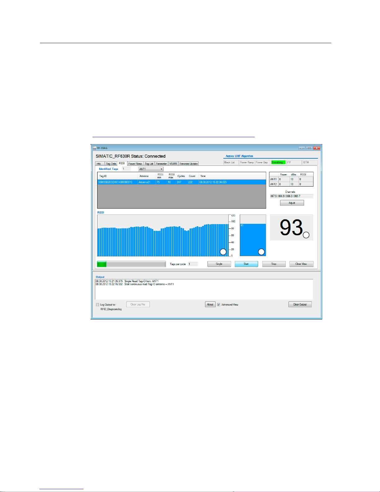
With the "RSSI" tab (Received Signal Strength Indikator) you can display the strength of the
received antenna signal and, if necessary, optimize the antenna alignment or transponder
position/distance. To allow optimum adaptation of the antenna, the RSSI values of the
transponders read by the reader are updated cyclically. The RSSI value indicates the signal
strength with which a transponder was recognized.
You will find further information on adapting the environmental conditions and the RSSI
value in "RF600 system manual
(http://support.automation.siemens.
com/WW/view/en/22437600)".
D E
F
Figure 5-4 The "RSSI" tab
From the drop-down list, you can select the data source with which the recording will be
made.
Page 39

Operating the software
5.3 The tabs of the RF640R/RF670R readers
SIMATIC RF-DIAG
Operating Manual, 09/2012, C79000-G8976-C292-01
39
Controlling the recording
Using the "Single", "Start", "Stop" and "Clear View", you can control the recording of the
RSSI values:
● Single setting
A single read of the selected data source is triggered and the measured values obtained
are displayed.
● Start
Existing values from a previous recording are deleted. A new recording is then started.
Reads of the selected data source are performed cyclically.
● Stop
Stopping the recording
● Deleting the display
Existing values from the last recording are deleted.
A progress bar indicates that the recording is active. The output box displays the number of
transponders read with the last read operation.
List of identified transponders
After you have started recording the RSSI values, all the transponders identified by the
reader are listed in the table.
Table 5- 4 Displayed properties of the recognized transponders
Property Description
Tag ID EPC ID of the detected transponder
Antenna Antenna with which the transponder was detected. Do not forget that the
transponder may also have been detected on a different antenna.
RSSI min Minimum RSSI value of the transponder. Calculated over all successful
inventories.
RSSI max Maximum RSSI value of the transponder. Calculated over all successful
inventories.
Cycles Number of inventories taken of this transponder.
Count Number of successful inventories of this transponder.
Time Time stamp when the transponder was last read.
To make it easier to identify the transponders and to assign the RSSI values, the
transponders are shown in different colors. 10 different colors are available for distinguishing
the transponders. If more transponders were read than the available colors, the colors are
repeated.
Transponders can be selected individually in the table. The selected transponder is
highlighted with the selection color set in Windows.
The sum of the identified transponders is displayed in the "Identified Tags" output box.
Page 40

Operating the software
5.3 The tabs of the RF640R/RF670R readers
SIMATIC RF-DIAG
40 Operating Manual, 09/2012, C79000-G8976-C292-01
Display of the RSSI values
The RSSI values of the transponders are shown in three representations:
● RSSI value according to transponders (a)
The bar diagram shows the RSSI values of the identified transponders in chronological
order. The Y axis shows the RSSI values of the transponder that were read. The X axis
shows the read access to the various transponders. With each read access, the RSSI
values of all identified transponders are represented as a bar.
The transponders are assigned the same colors as in the table above. If a transponder is
selected in the table, the transponder in the bar diagram also changes to the selection
color.
If no transponder is identified during the read, a bar with the RSSI value "0" (no bar) is
displayed.
With this representation, you can recognize quickly and simply when a transponder is not
read with every access.
● Current RSSI value (b, c)
The last measured RSSI value is shown in a further bar. With the aid of this view, you can
quickly find the ideal alignment for the highest RSSI value by varying the antenna
position.
The current RSSI value of the selected transponder is also displayed as a numeric value.
Note
RSSI display when changing data sources
If the data source is changed in other tabs when recording RSSI values, the display of the
previously measured RSSI values of the previous data source is retained on screen. The
RSSI values of the other data source are added.
This behavior can be avoided using "Clear View".
Page 41
Operating the software
5.3 The tabs of the RF640R/RF670R readers
SIMATIC RF-DIAG
Operating Manual, 09/2012, C79000-G8976-C292-01
41
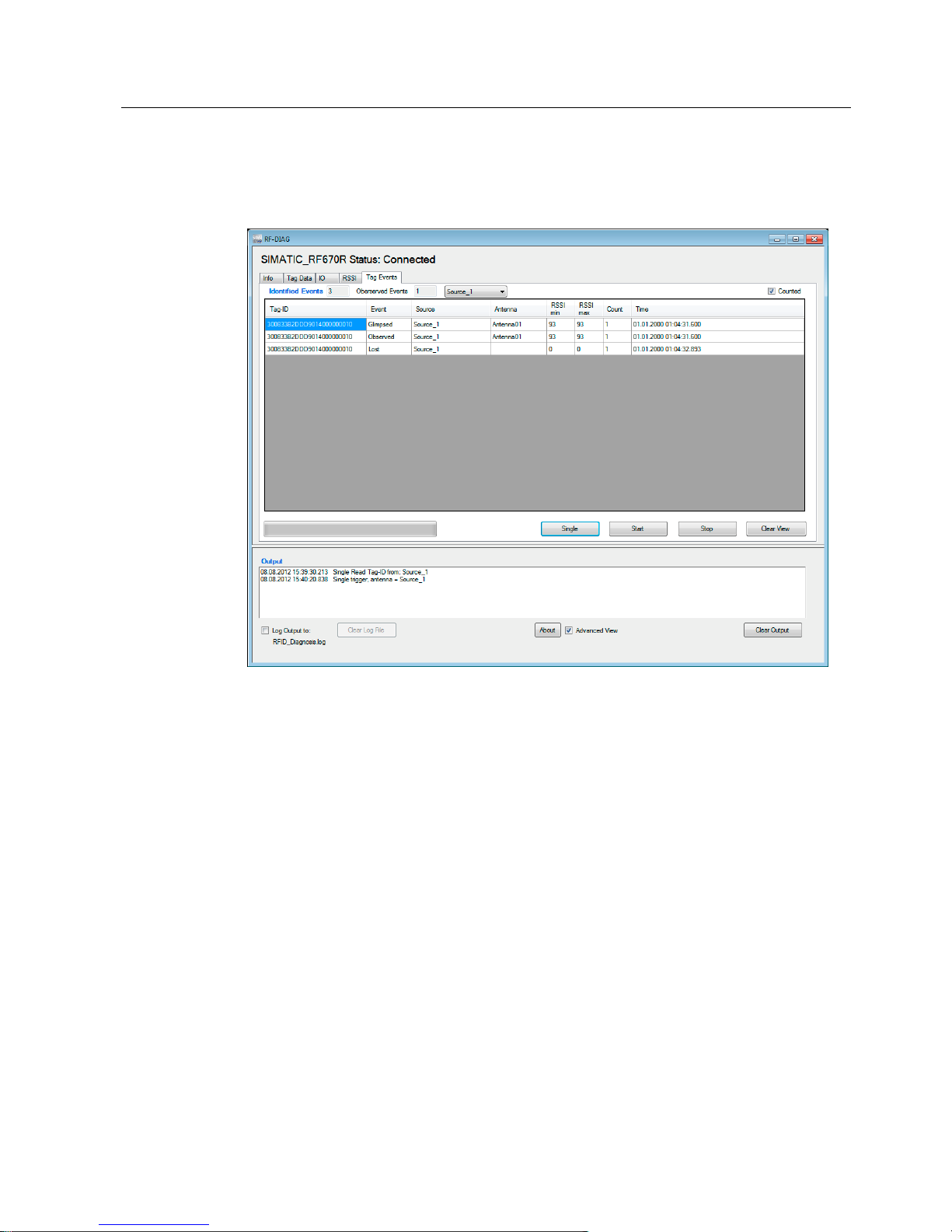
5.3.5 The "Tag Events" tab
Using the "Tag Events" tab, you can verify tag events quickly and simply.
Figure 5-5 The "Tag Events" tab
From the drop-down list, you can select the data source with which the recording will be
made.
Controlling recordings
Using the "Single", "Start", "Stop" and "Clear View", you can control the recording of the
events:
● Single setting
A single read of the selected data source is triggered and the measured values obtained
are displayed.
● Start
Any existing values from a previous recording are not deleted. A new recording is then
started. Reads of the selected data source are performed cyclically.
Page 42

Operating the software
5.3 The tabs of the RF640R/RF670R readers
SIMATIC RF-DIAG
42 Operating Manual, 09/2012, C79000-G8976-C292-01
● Stop
Stopping the recording
● Deleting the display
Existing values from the last recording are deleted.
A progress bar indicates that the recording is active.
Displaying the events
After starting the recording of the events, the number of identified events and the number of
observed events are displayed. The table lists all the events sent by the reader.
With the "Counted" check box, you can change the table mode to display a compressed
table. If you have selected the check box the "Counted" mode is active. If you have not
selected the check box the "Time" mode is active.
The two table modes:
● Quantity
Compact overview - recommended if large numbers of transponders are involved. In this
mode, only different events are displayed. If an event is repeated on a transponder, only
the existing row is updated.
● Time (default)
Detailed overview - each event is displayed in a separate row. This makes the
chronological sequence of the events clear.
Table 5- 5 Displayed properties of the Tag Events
Property Description
Tag ID EPC ID of the detected transponder
Event Type of event (New, Glimpsed, Observed, Lost). Depending on the configuration in
RF-MANAGER Basic, only a selection of the possible events is generated.
Data source Data source with which the transponder was detected.
Antenna Antenna with which the transponder was detected. Do not forget that the
transponder may also have been detected on a different antenna.
RSSI 1) RSSI value of the transponder that was calculated for this event.
RSSI min 2) Minimum RSSI value of the transponder. Calculated over all events of this
transponder.
RSSI max 2) Maximum RSSI value of the transponder. Calculated over all events of this
transponder.
Count 2) Number of identical events of this transponder.
Time Time stamp when the transponder was last read.
1)
exists only in "Time" mode
2)
exists only in "Counted" mode
Page 43
Operating the software
5.4 The tabs of the RF620R/RF630R readers
SIMATIC RF-DIAG
Operating Manual, 09/2012, C79000-G8976-C292-01
43
5.4 The tabs of the RF620R/RF630R readers
5.4.1 The "Info" tab
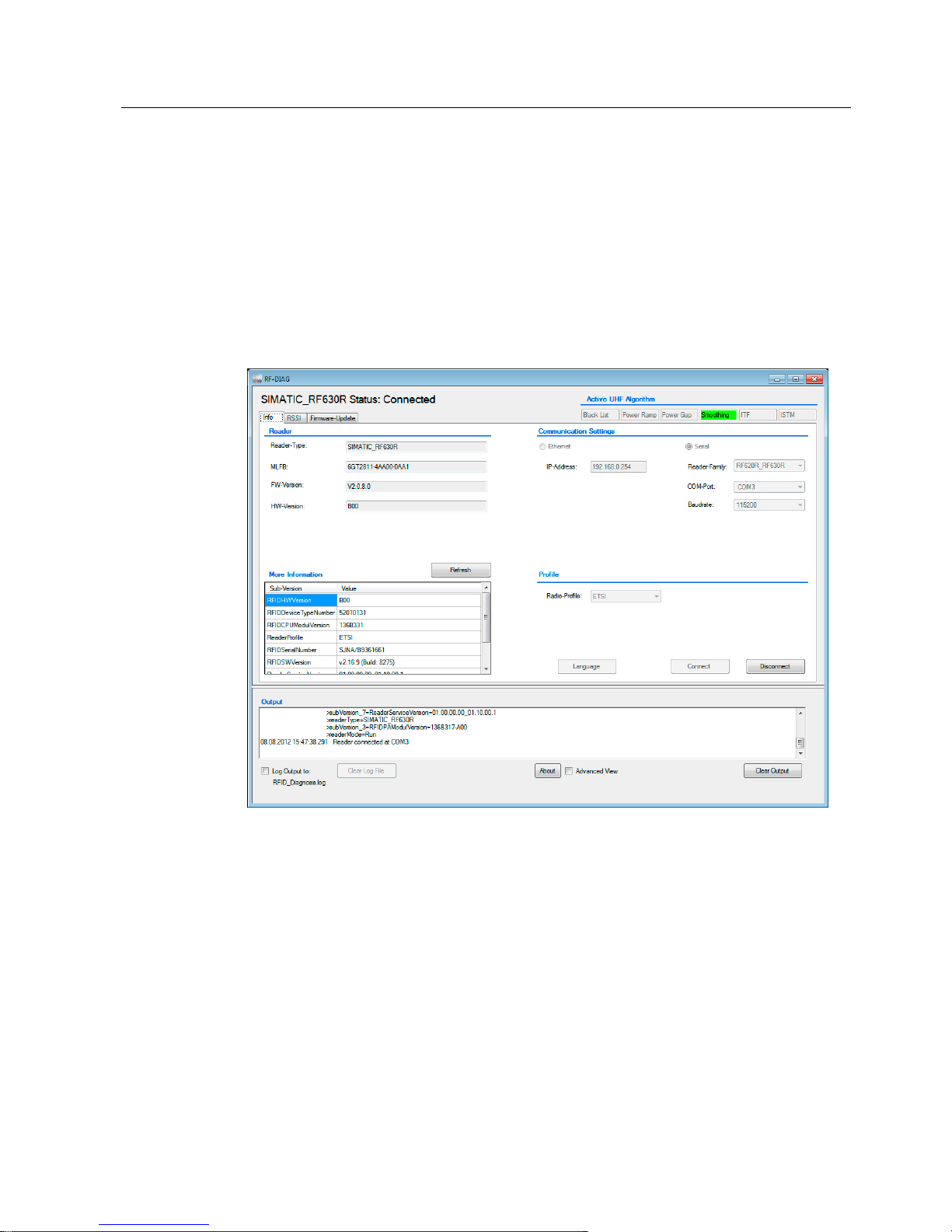
With the functions on the "Info" tab, you can establish the connection to the reader. This tab
is always displayed regardless of the connected reader type or the current connection status.
Following successful connection establishment to a reader, important basic information of
the reader is displayed.
Figure 5-6 The "Info" tab following successful connection establishment to an RF630R
Page 44

Operating the software
5.4 The tabs of the RF620R/RF630R readers
SIMATIC RF-DIAG
44 Operating Manual, 09/2012, C79000-G8976-C292-01
Establishing a connection to serially connected readers
To establish a connection to a serially connected reader, follow the steps below:
1. In the "Communication Settings" area, select "Serial".
2. From the "Reader Family" drop-down list, select the reader time currently connected to
the PC.
3. From the "COM Port" drop-down list, select the port currently being used. The
requirements for communication using the USB driver of the PC adapter for SIMATIC RFDIAG and the selection of the COM port can be found in the section "Installation and use
of the USB driver
(Page 23)".
4. From the "Baudrate" drop-down lis
t, select the baud rate that was stored on the CM.
5. In the "Profile" area, select the radio profile used by the reader currently connected to the
PC from the "Radio Profile" drop-down list.
6. Click the "Connect" button.
Reaction: The connection to the reader is established. The basic information of the reader is
displayed in the "Reader" area.
Note
Switchover to diagnostics mode
As soon as the connection to a reader is established via the diagnostics tool, the reader
changes to diagnostics mode. During diagnostics mode, you can change parameters on the
reader using the diagnostics tool.
Switching back to communication mode
To disconnect the diagnostics tool from the reader, follow the steps below:
1. Click the "Disconnect" button.
2. Disconnect the USB cable from the adapter.
The reader is automatically returned to communications mode to be able to communicate
with the CM. This ensures problem-free communication between the reader and controller.
Note
Return to communications mode with the CM
If the reader is disconnected from the USB cable during diagnostics mode, you may need to
restart the reader to be able to operate it via the CM again.
Changing the language
In the "Info" tab, you can change the language of the software user interface. Click the
"Language" button to change the software user interface to German or English.
Page 45
Operating the software
5.4 The tabs of the RF620R/RF630R readers
SIMATIC RF-DIAG
Operating Manual, 09/2012, C79000-G8976-C292-01
45
5.4.2 The "Tag Data" tab
The "Tag Data" tab is displayed only in the advanced view.
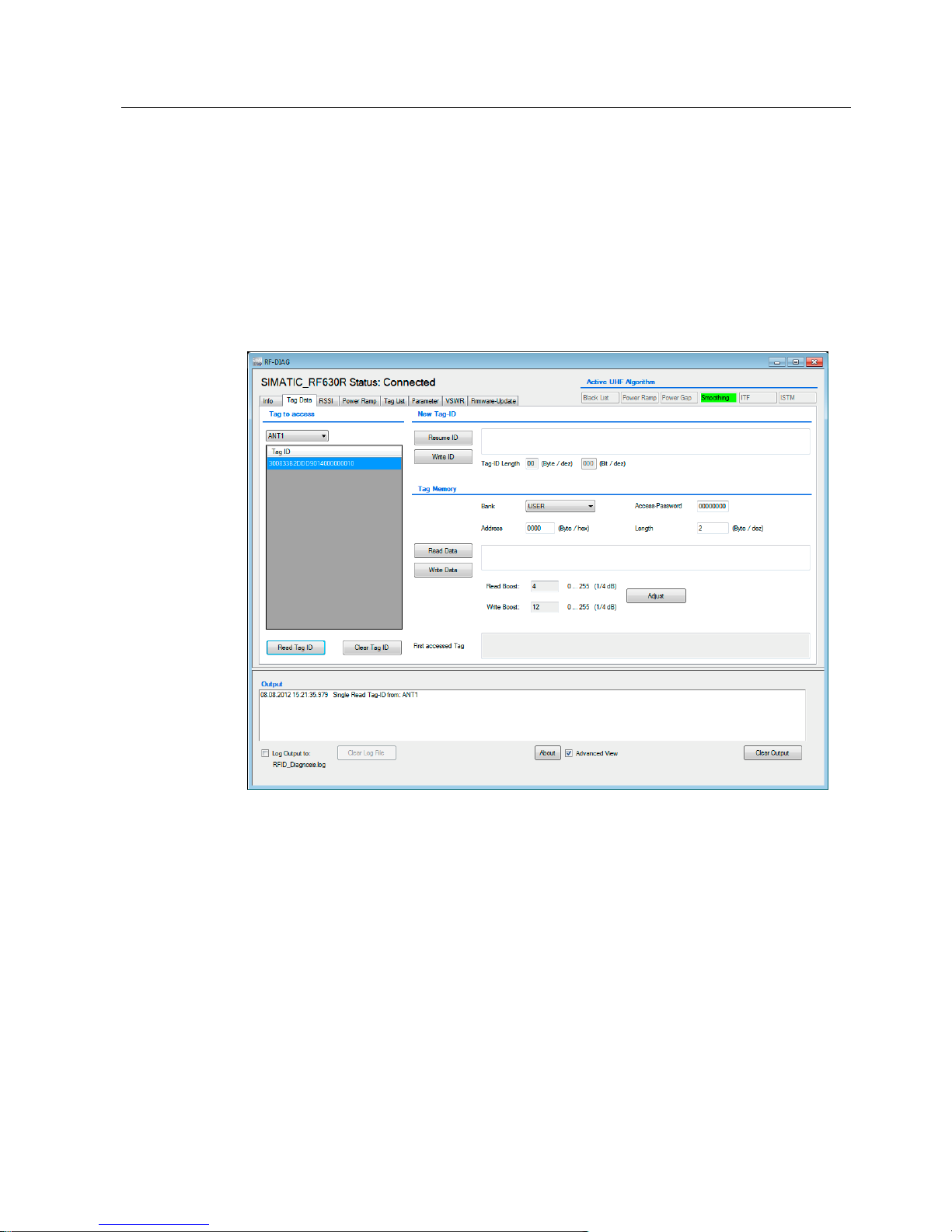
Using the "Tag Data" tab, you can verify the transponder data and the basic function of a
reading point quickly and simply. In this tab, you can read out any data from the transponder
or write to the transponder. When writing to the transponder, you can address all memory
areas of the transponder. With a single command, a maximum of 64 bytes can be read or
written.
You can also change the EPC-ID of the transponder.
Figure 5-7 The "Tag Data" tab
Selecting transponders
In the drop-down list of the "Tag to access" area, you can choose the antenna via which the
reader will establish the connection to the transponder.
The "Tag ID" list contains all the transponders in the antenna field. You can update the list
with the "Read Tag ID" button. From this list, select the transponder for which you want to
use write or read operations.
Page 46

Operating the software
5.4 The tabs of the RF620R/RF630R readers
SIMATIC RF-DIAG
46 Operating Manual, 09/2012, C79000-G8976-C292-01
Assigning a new tag ID
To assign a new tag ID to a transponder, follow the steps below:
1. Click the "Read Tag ID" button.
2. Select the required transponder in the "Tag ID" list.
3. In the "New Tag-ID" area, click the "Resume ID" button to accept the current tag ID of the
transponder.
Reaction: The ID of the transponder is displayed as a hexadecimal character string in the
input box.
4. Adapt the tag ID displayed in the input field as required.
The tag ID length to be written is decided by the number of characters and specified in
bytes or bits in two output boxes.
5. Click the "Write ID" button to transfer the new ID to the transponder.
Reaction: The tag ID is written to the transponder.
Note
Error message "Weak Power"
If the error message "Weak Power" appears after writing the tag ID, it is possible that the
new tag ID of the transponder was not overwritten. In this case read out the tag ID again
and, if necessary repeat the write function.
If necessary, increase the transmit power as described in the section "6.2 (Page 67)".
Reading/writing tag data
In the "Tag Memory" area, you can address all memory areas of an ISO 18000-6C
transponder. You can read/write specific data using the "Bank" drop-down list and the two
input boxes "Address" and "Length". To read/write a protected transponder, you will need to
specify the "Access Password" of the transponder.
Click the "Read Data" button to read out the data of the transponder. The data read out is
displayed in the input box as a hexadecimal character string. With the "Write Data" button,
you can write the data in the input box to the transponder.
In the "Address" input box, you set the address offset (in bytes) of the selected memory bank
(EPC, USER, RESERVED, TID). The meaning of the bytes for each memory bank is
according to ISO 18000-6C.
Note
"Tag to access" list is empty or was deleted
If the "Tag to access" list is empty or has been deleted, read/write commands then apply to
all transponders in the input box.
Page 47

Operating the software
5.4 The tabs of the RF620R/RF630R readers
SIMATIC RF-DIAG
Operating Manual, 09/2012, C79000-G8976-C292-01
47
Note
"First accessed Tag"
The first transponder to be processed is always displayed. If more than one transponder was
processed in the input box, the list of the EPC IDs of all processed transponders can be
seen in "Output". If there is only one transponder that was processed in the input box, this is
displayed.
Note
Increasing the power setting if reading the tag IDs is unsuccessful
"Read Boost" and "Write Boost" are only added to the power setting, see "RSSI" or "Power
Ramp" tabs. If you want to improve recognition of transponders, increase the power
"Distance limiting (Power)" in one of the tabs"RSSI", "Power Ramp" or "Parameter".
When the maximum possible power setting of a reader has been reached, "Read Boost" or
"Write Boost" no cause an increase in power.
If reading out or writing to a transponder fails, you can increase the power. Click the
"Change" button. In the dialog box that opens, specify the number of 1/4 dB steps by which
you want to increase the power. Changes in the "Read Boost" input box increase the power
when reading data. Changes in the "Write Boost" input box increase the power when writing
data.
Note
Effect of "Read Boost"
"Read Boost" is only effective with "Read Data" and otherwise it is not effective, for example
with "Read Tag ID".
Page 48
Operating the software
5.4 The tabs of the RF620R/RF630R readers
SIMATIC RF-DIAG
48 Operating Manual, 09/2012, C79000-G8976-C292-01
5.4.3 The "RSSI" tab
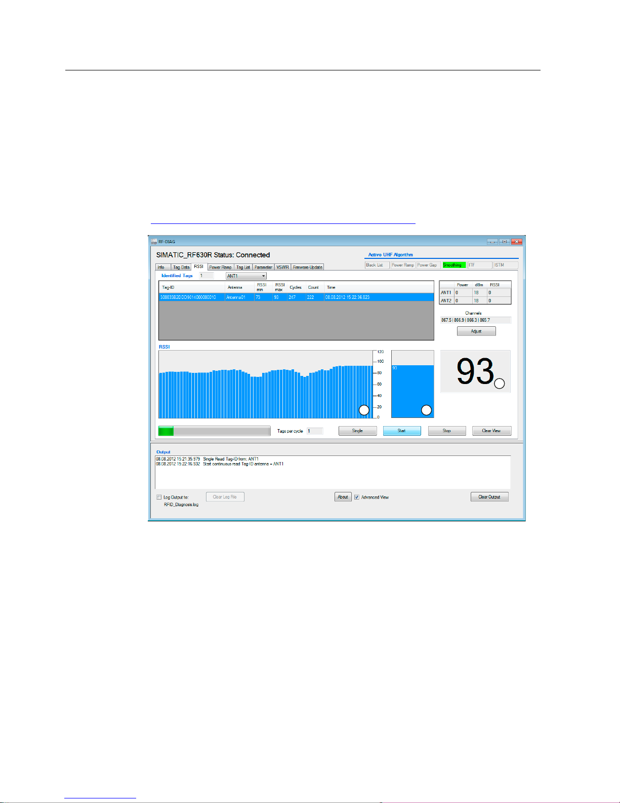
With the "RSSI" tab (Received Signal Strength Indikator) you can display the strength of the
received antenna signal and, if necessary, optimize the antenna alignment or transponder
position/distance. To allow optimum adaptation of the antenna, the RSSI values of the
transponders read by the reader are updated cyclically. The RSSI value indicates the signal
strength with which a transponder was recognized.
You will find further information on adapting the environmental conditions and the RSSI
value in "RF600 system manual
(http://support.automation.siemens.
com/WW/view/en/22437600)".
D E
F
Figure 5-8 The "RSSI" tab
From the drop-down list, you can select the antenna with which the recording will be made.
Page 49

Operating the software
5.4 The tabs of the RF620R/RF630R readers
SIMATIC RF-DIAG
Operating Manual, 09/2012, C79000-G8976-C292-01
49
Controlling the recording
Using the "Single", "Start", "Stop" and "Clear View", you can control the recording of the
RSSI values:
● Single setting
A single read of the selected antenna is triggered and the measured values obtained are
displayed.
● Start
Existing values from a previous recording are deleted. A new recording is then started.
Reads of the selected antenna are performed cyclically.
● Stop
Stopping the recording
● Deleting the display
Existing values from the last recording are deleted.
A progress bar indicates that the recording is active. The output box displays the number of
transponders read with the last read operation.
List of identified transponders
After you have started recording the RSSI values, all the transponders identified by the
reader are listed in the table.
Table 5- 6 Displayed properties of the recognized transponders
Property Description
Tag ID EPC ID of the detected transponder
Antenna Antenna with which the transponder was detected. Do not forget that the
transponder may also have been detected on a different antenna.
RSSI min Minimum RSSI value of the transponder. Calculated over all successful
inventories.
RSSI max Maximum RSSI value of the transponder. Calculated over all successful
inventories.
Cycles Number of inventories taken of this transponder.
Count Number of successful inventories of this transponder.
Time Time stamp when the transponder was last read.
To make it easier to identify the transponders and to assign the RSSI values, the
transponders are shown in different colors. 10 different colors are available for distinguishing
the transponders. If more transponders were read than the available colors, the colors are
repeated.
Transponders can be selected individually in the table. The selected transponder is
highlighted with the selection color set in Windows.
The sum of the identified transponders is displayed in the "Identified Tags" output box.
Page 50
Operating the software
5.4 The tabs of the RF620R/RF630R readers
SIMATIC RF-DIAG
50 Operating Manual, 09/2012, C79000-G8976-C292-01
Display of the RSSI values
The RSSI values of the transponders are shown in three representations:
● RSSI value according to transponders (a)
The bar diagram shows the RSSI values of the identified transponders in chronological
order. The Y axis shows the RSSI values of the transponder that were read. The X axis
shows the read access to the various transponders. With each read access, the RSSI
values of all identified transponders are represented as a bar.
The transponders are assigned the same colors as in the table above. If a transponder is
selected in the table, the transponder in the bar diagram also changes to the selection
color.
If no transponder is identified during the read, a bar with RSSI value "0" (no bar) is
displayed.
With this representation, you can recognize quickly and simply when a transponder is not
read with every access.
● Current RSSI value (b, c)
The last measured RSSI value is shown in a further bar. With the aid of this view, you can
quickly find the ideal alignment for the highest RSSI value by varying the antenna
position.
The current RSSI value of the selected transponder is also displayed as a numeric value.
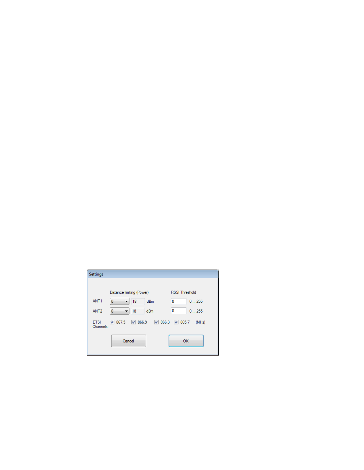
Setting reader parameters
With the "Adjust" button, you can change the most important reader parameters, such as
antenna power or RSSI Threshold. With readers for the ETSI radio profile, you can also
specify the ETSI channels that the reader will use in this dialog box.
Figure 5-9 Changing reader parameters in the "RSSI" tab
The changed parameters are only valid when the program is running. In other words, the
parameters are not stored permanently on the reader. In the "Parameter" tab, you can save
the parameter configurations retentively.
Page 51
Operating the software
5.4 The tabs of the RF620R/RF630R readers
SIMATIC RF-DIAG
Operating Manual, 09/2012, C79000-G8976-C292-01
51
You will find more information on parameters in the section "The "Parameters" tab
(Page 58)" or in "Parameter assignment manual RF620R/RF630R
(http://support.automation.siemens.
com/WW/view/en/33287195)".
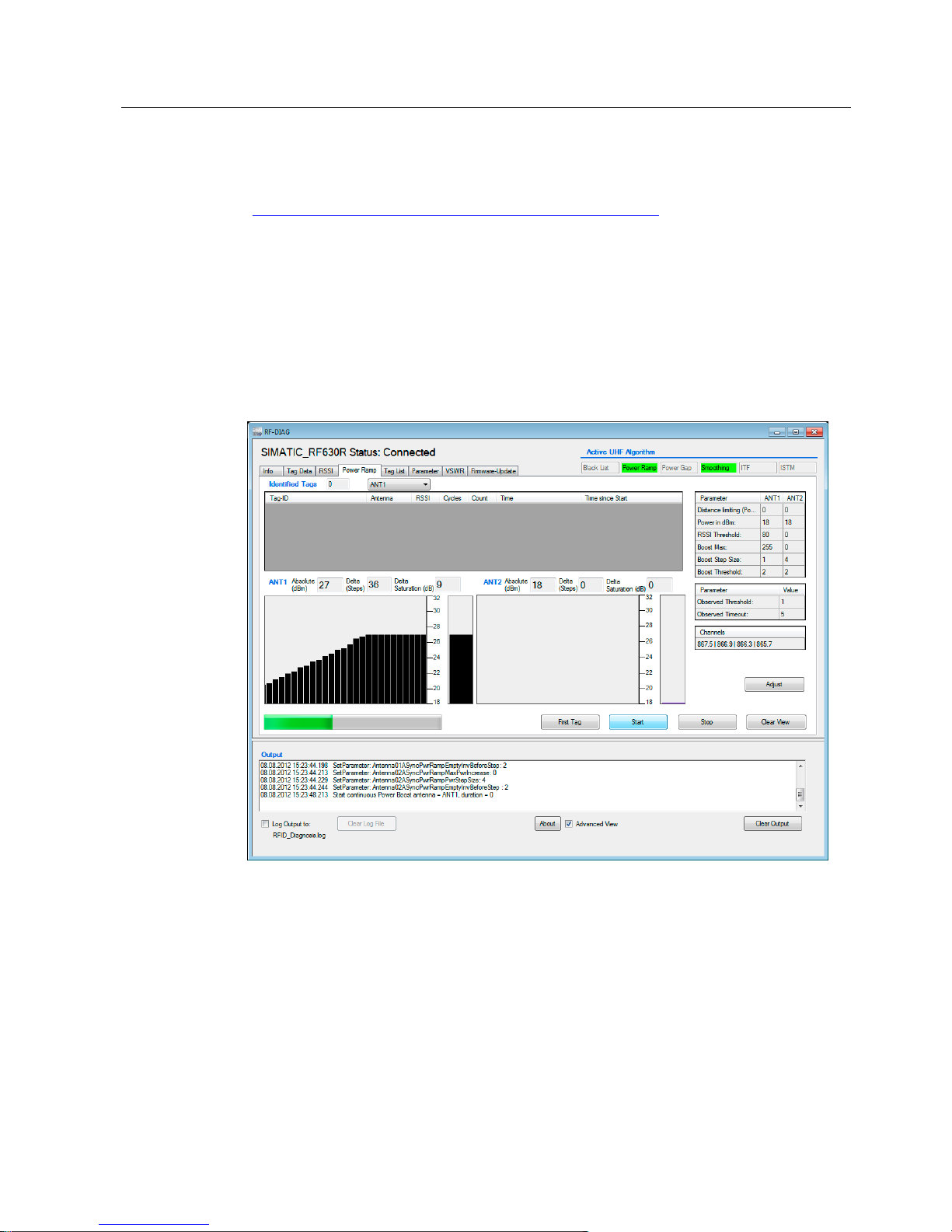
5.4.4 The "Power Ramp" tab
The "Power Ramp" tab is displayed only in the advanced view.
With the "Power Ramp" tab, you can display the current transmit/radiated power of the
readers/antennas. This allows you to make an optimum setting for the "Power Ramp".
The currently used transmit power (RF630R) or radiated power (RF620R) of the reader per
read access is displayed.
Figure 5-10 The "Power Ramp" tab
Page 52

Operating the software
5.4 The tabs of the RF620R/RF630R readers
SIMATIC RF-DIAG
52 Operating Manual, 09/2012, C79000-G8976-C292-01
Controlling recordings
Using the "First Tag", "Start", "Stop" and "Clear View", you can control the recording of the
transmit/radiated power:
● First Tag
Cyclic reads are triggered on the selected antenna and the measured values obtained
are displayed. The recording is stopped automatically when a transponder is identified
the first time.
● Start
Any existing values from a previous recording are deleted. A new recording is then
started. Reads of the selected antenna are performed cyclically.
● Stop
Stopping the recording
● Deleting the display
Existing values from the last recording are deleted.
A progress bar indicates that the recording is active.
List of identified transponders
After you have started recording the transmit/radiated power, all the transponders identified
by the reader are listed in the table.
Table 5- 7 Displayed properties of the recognized transponders
Property Description
Tag ID EPC ID of the detected transponder
Antenna Antenna with which the transponder was detected. Only one antenna is ever
displayed here. With this display, you cannot recognize the antenna or antennas
that detected the transponder or whether several antennas detected the
transponder.
RSSI RSSI value with which the transponder was last read.
Cycles Number of inventories since this transponder was identified the first time
Count Number of successful inventories of this transponder.
Time Time stamp when the transponder was last read.
Time since Start The time in [ms] that has elapsed since the start of the test and the first successful
read of the transponder.
The color in the table row indicates whether or not the transponder was identified during the
last inventories:
Green Transponder was identified during the last inventory
Light green Transponder was not identified only during the last inventory
Red Transponder was not identified during the last two inventories
The sum of the identified transponders is displayed in the "Identified Tags" output box.
Page 53

Operating the software
5.4 The tabs of the RF620R/RF630R readers
SIMATIC RF-DIAG
Operating Manual, 09/2012, C79000-G8976-C292-01
53
Display of the transmit power/radiated power
The current values for the transmit/radiated power of the readers/antennas is shown in two
identically structured views.
The output boxes
The output boxes "Absolute", "Delta" and "Delta Saturation" display the absolute
transmit/radiated power, the number of power increases in 0.25 dB steps and the effective
increase in power in [dB]. Theoretically the transmit/radiated power can be increased by up
to 255 steps (63.75 dB) ("Delta"). Since the maximum transmit/radiated power of the reader
is limited, the "Delta Saturation" output box displays the effective increase in power.
The bar diagram
The bar diagram shows the transmit/radiated power over time. For each read access, a bar
is shown on the X axis with the transmit/radiated power used.
With this representation, you can see very quickly and easily how the transmit/radiated
power changes. In particular, this visualizes the use of the Power Ramp and its effects on
the transmit/radiated power.
The transmit/radiated power used for the last measurement is shown separately as a bar.
With this view, you can see the current value at a glance.
Note
Dependency of the bar diagram representation of reader hardware, PC hardware and
operating system
The bar diagram representation of Power Ramp depends on the performance of the PC
hardware, the operating system and the reader hardware.
Page 54
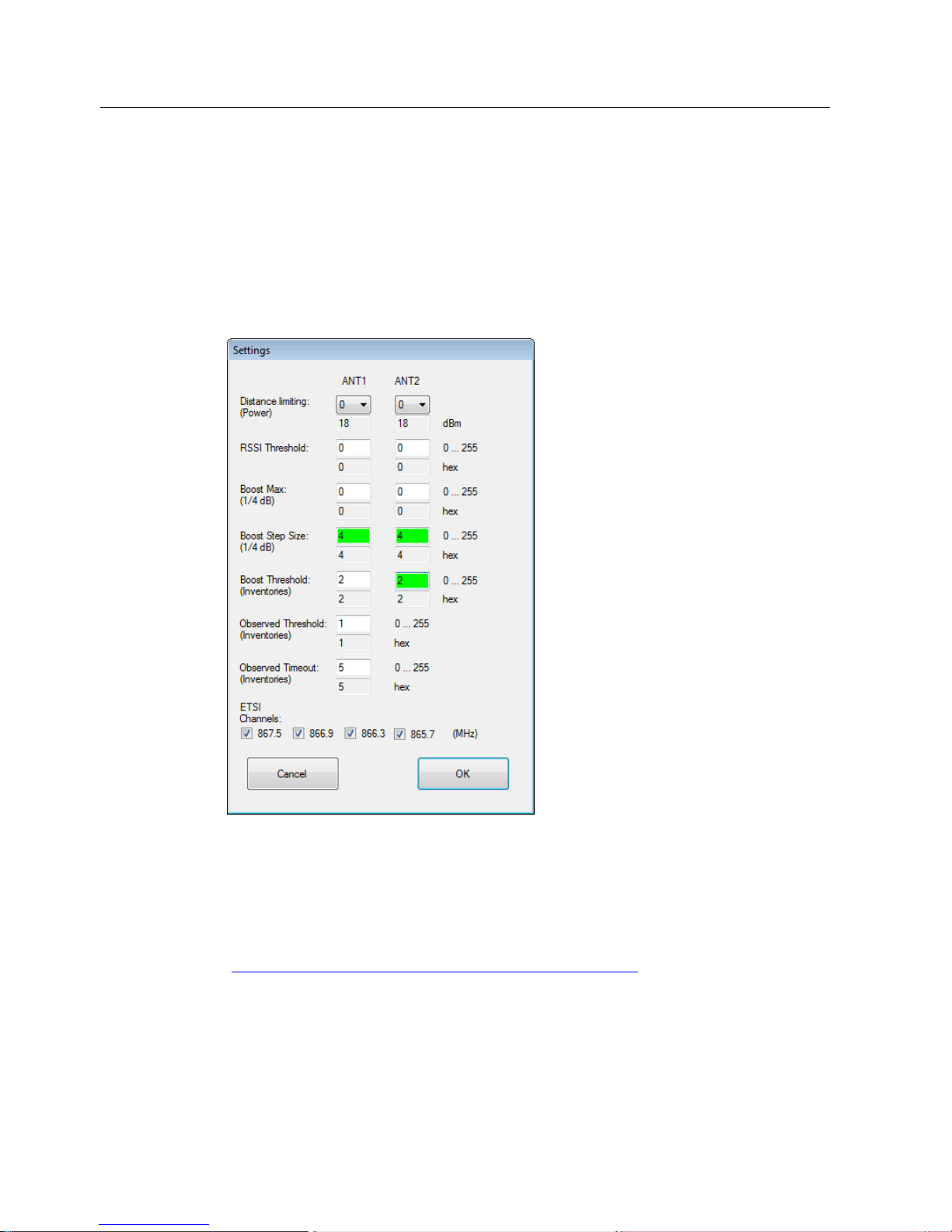
Operating the software
5.4 The tabs of the RF620R/RF630R readers
SIMATIC RF-DIAG
54 Operating Manual, 09/2012, C79000-G8976-C292-01
Power Ramp - setting parameters
Using the "Adjust" button, you can change the parameters required for the Power ramp and
select ETSI channels (analogous to the "RSSI" tab). You can also activate automatic
increases in the transmit/radiated power. Depending on your entries, the transmit/radiated
power of the antenna is increased in ¼ dB steps if the transponder is not identified during an
inventory.
For readers with the ETSI radio profile, you can also specify the ETSI channels for which the
changes will be effective in this dialog box.
Figure 5-11 "Power Ramp - changing parameters
The changed parameters are only valid when the program is running. In other words, the
parameters are not stored permanently on the reader. In the "Parameter" tab, you can save
the parameter configurations retentively.
You will find more information on parameters in the section "The "Parameters" tab
(Page 58)" or in "Parameter assignment manual RF620R/RF630R
(http://support.automation.siemens.
com/WW/view/en/33287195)".
Page 55
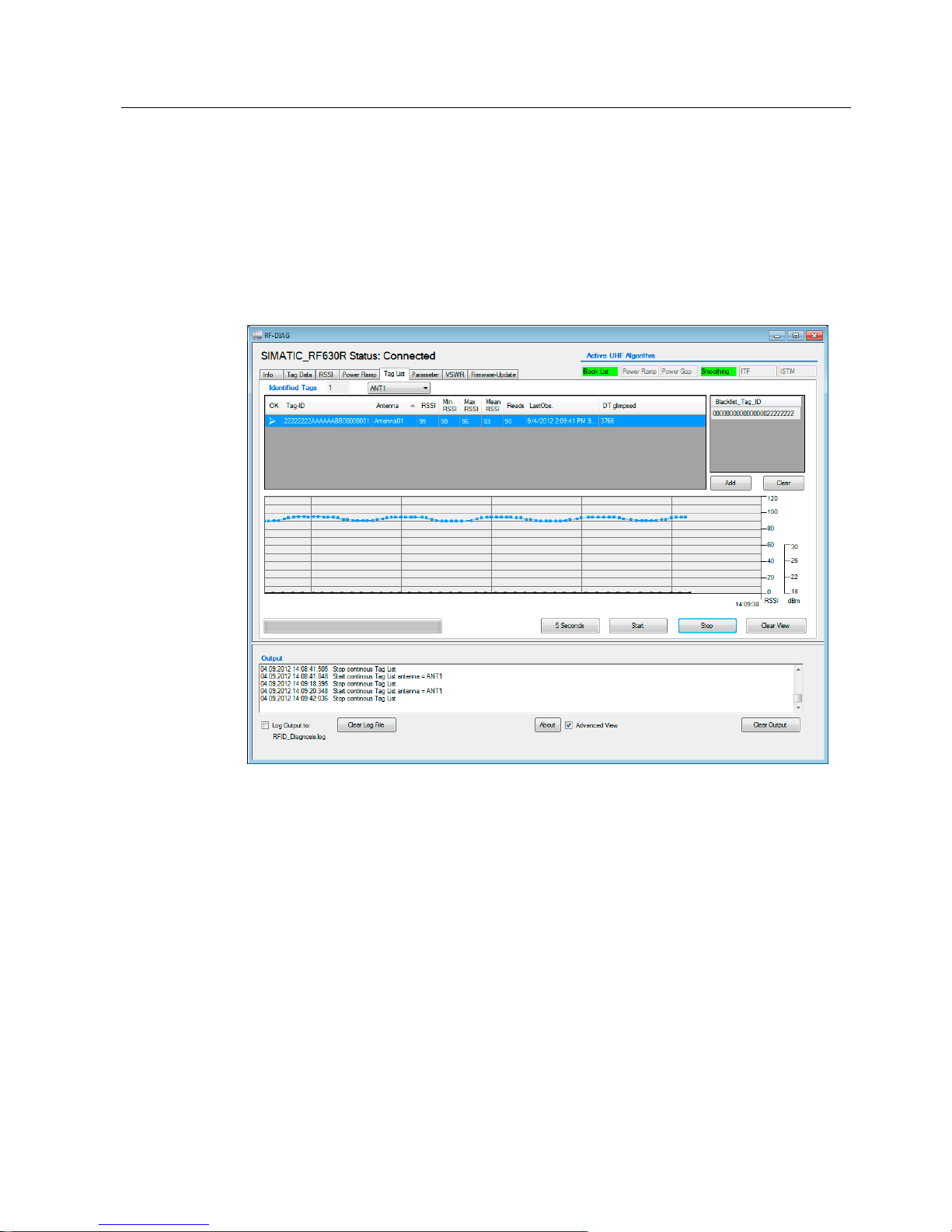
Operating the software
5.4 The tabs of the RF620R/RF630R readers
SIMATIC RF-DIAG
Operating Manual, 09/2012, C79000-G8976-C292-01
55
5.4.5 The "Tag List" tab
The "Tag List" tab is displayed only in the advanced view.
In the "Tag List" tab, you will see list of all the transponders identified by the reader. With this
tab, you can read out the RSSI values of each individual identification of a transponder and
therefore check the effectiveness of all active UHF algorithms (for example Power Ramp,
Smoothing, ISTM). Disabled transponders are displayed in the Black List assuming that you
have activated the Black List in the "Parameter" tab.
Figure 5-12 The "Tag List" tab
Controlling recordings
Using the "5 Seconds", "Start", "Stop" and "Clear View", you can control the recording of the
transponders:
● 5 Seconds
The recording is started and automatically stopped after 5 seconds. This functionality
cannot be selected if the ITF feature is active.
● Start
Any existing values from a previous recording are deleted. A new recording is then
started.
Page 56

Operating the software
5.4 The tabs of the RF620R/RF630R readers
SIMATIC RF-DIAG
56 Operating Manual, 09/2012, C79000-G8976-C292-01
● Stop
Stopping the recording
● Deleting the display
Existing values from the last recording are deleted.
A progress bar indicates that the recording is active.
List of identified transponders
After you have started recording, all the transponders identified by the reader are listed in the
table.
Table 5- 8 Displayed properties of the recognized transponders
Property Description
OK Symbol indicating whether the transponder was detected as valid by the reader.
If the reader is operating in Smoothing mode, the transponder needs to be
detected Observed Threshold number of times.
Tag ID EPC ID of the detected transponder
Antenna Antenna with which the transponder was detected. Only one antenna is ever
displayed here. With this display, you cannot recognize the antenna or antennas
that detected the transponder or whether several antennas detected the
transponder.
RSSI RSSI value with which the transponder was last read.
RSSI min Minimum RSSI value of the transponder. Calculated over all successful
inventories.
RSSI max Maximum RSSI value of the transponder. Calculated over all successful
inventories.
Mean RSSI Average RSSI value of the transponder.
Reads Number of successful inventories of the transponder.
LastObs. Time stamp when the transponder was last read.
DT glimpsed Time that has elapsed in [ms] between the first and last successful transponder
read.
Page 57

Operating the software
5.4 The tabs of the RF620R/RF630R readers
SIMATIC RF-DIAG
Operating Manual, 09/2012, C79000-G8976-C292-01
57
Note
Marking the transponders
All transponders that remain following filtering of all activated algorithms are marked "OK".
The possible activated filters include the following:
1. Black List
2. Smoothing or Inventory Threshold Filter
3. Sorting the ISTM
If the ISTM is activated, all transponders remaining after filtering 1 and 2 and that are within
the minimum distance of the set sorting criterion are marked as OK.
During processing on the PLC in the case above, if more than 1 transponder is marked with
"OK, no tag would be displayed in the Tag List. This applies only to Singletag Mode.
To make it easier to identify the transponders and to assign the transmit/radiated power, the
transponders are shown in different colors. 10 different colors are available for distinguishing
the transponders. If more transponders were read than the available colors, the colors are
repeated.
Transponders can be selected individually in the table. The selected transponder is
highlighted with the selection color set in Windows.
The sum of the identified transponders is displayed in the "Identified Tags" output box.
Displaying and working with the Black List
This is only displayed if the UHF algorithm "Black List" has been activated in the "Parameter"
tab. With the "Add" buttons, you can transfer selected transponders from the list of identified
transponders to the Black List. These transponders are removed from the list and the tag ID
of the transponder is entered in the Black List. Transponders in the Black List are no longer
read out and are no longer displayed during future recordings.
With the "Clear" button, all the transponders in the "Black List" can be deleted from the Black
List.
Display of the RSSI values and the transmit/radiated power
The diagram shows both the RSSI values of all read transponders as well as the
transmit/radiated power of the reader.
To make identification easier, the lines of the RSSI values of the transponders are shown in
the same color that was assigned to the transponders earlier in the list of identified
transponders.
The RSSI values of the transponders are shown as individual dots. If you select a
transponder in the list of identified transponders, the dots in the diagram are connected
together by a thin line.
The transmit power of the reader is shown as a thick line. The measuring points are
highlighted as dots on the line.
Page 58
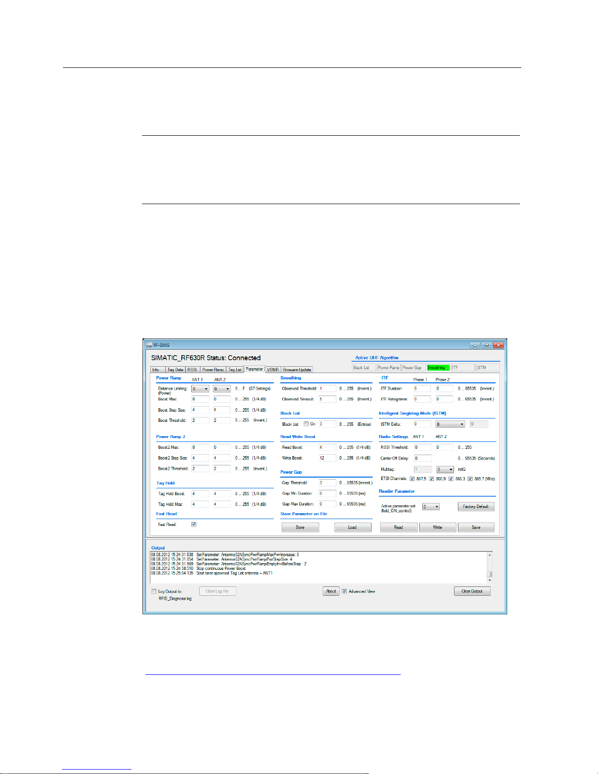
Operating the software
5.4 The tabs of the RF620R/RF630R readers
SIMATIC RF-DIAG
58 Operating Manual, 09/2012, C79000-G8976-C292-01
The transmit power of ANT1 is shown as a black line and the transmit power of ANT2 as a
violet line.
Note
Time stamp of the transmit/radiated power
The time stamp for the transmit/radiated power is generated by the diagnostics tool. This
means that there may be slight deviations in the times of RSSI measured values and the
times of the measured transmit/radiated power.
5.4.6 The "Parameters" tab
The "Parameter" tab is displayed only in the advanced view.
With the "Parameter" tab, you can activate, read out, enter, adapt and write the various
parameters and store them on the reader. This gives you the option of generating different
configurations and loading them again later. Laborious manual re-entry of configurations is
therefore unnecessary.
Figure 5-13 The "Parameters" tab
You will find a description of the UHF algorithms and the individual parameters in "Parameter
assignment manual RF620R/RF630R
(http://support.automation.siemens.
com/WW/view/en/33287195)".
Page 59

Operating the software
5.4 The tabs of the RF620R/RF630R readers
SIMATIC RF-DIAG
Operating Manual, 09/2012, C79000-G8976-C292-01
59
The buttons of the "Parameter" tab:
● Back up
Click the "Store" button to store all currently set parameters on your PC or PG. You can
select the name and storage location of the file yourself.
Note
File with prefix "AUP:" or "RESET:"
All the parameters that represent expert parameters are given the "AUP:" prefix in the file
when they are written.
All parameters that were set in communications mode or using Reset are given the
"RESET:" prefix in the file when they are written.
● Download
Click the "Load" button to reload the parameters from the saved file.
● Factory setting
Click the "Factory Default" button to reset the reader to the factory settings.
Note
Changed parameters are lost
All changed parameters in the active parameter set on the reader and on the user
interface are reset to the factory settings.
● Active parameters set
Two parameter sets are stored on the reader. Using the drop-down list, you can read out,
write and save different parameter sets (0 and 2). To be able to process a parameter set
with the diagnostics tool, you need to select the parameter set from the drop-down list
and then click the "Read" button.
● Read
Click the "Read" button to read out all the parameters from the reader and enter them in
the display boxes.
● Write
Click the "Write" button to transfer changed parameters to the reader.
Note
Parameters not permanently overwritten
Parameters that were set using "init_run" in PLC mode are NOT stored retentively on the
reader, not even after clicking the "Store" button. With the next "init_run", the data is
overwritten again. This applies to the parameters "Distance Limiting (Power)", "Multitag",
"InitQ", "ETSI Channels" and "Black List".
● Store
Click the "Store" button to save the parameters permanently on the reader.
Page 60

Operating the software
5.4 The tabs of the RF620R/RF630R readers
SIMATIC RF-DIAG
60 Operating Manual, 09/2012, C79000-G8976-C292-01
The parameters
Parameter Description
Power Ramp Specifies the step-by-step increase in the transmit/radiated power per antenna.
Power Ramp automatically increases the power if a transponder was not identified
during read/write access.
Power Ramp 2 Specifies the step-by-step increase in the transmit/radiated power per antenna.
Power Ramp increases the power automatically if a transponder was not identified
during read/write access and ITF phase 2 was activated in the parameter settings.
Tag Hold If the Tag Hold algorithm is active, an identified transponder is saved on the reader
with the first "READ" / "WRITE" access. In contrast to the normal mode, if Tag
Hold is activated, all subsequent "READ" / "WRITE" commands execute only for
this transponder.
Fast Read Specifies whether the transponder ID is read out again (deactivated) or whether
the ID is read out from the reader memory (activated).
Smoothing Specifies how often a transponder must be detected before the reader performs
read/write access. Alternative to ITF. Smoothing is the default setting.
Black List The Black List algorithm is used to hide transponders that have already been
processed. Using the Black List algorithm, overshoots etc. can be avoided in
difficult UHF environments. With the aid of the Black List, you can specify the size
of the ring buffer (entries).
Read/Write
Boost
Specifies a fixed transmit/radiated power increase of an antenna in ¼ dB steps for
read/write access.
Power Gap Specifies gaps between read/write accesses. Power Gap allows undisturbed
reading/writing of transponders when there is a high reader density.
ITF Specifies the number of inventories in which a transponder must be detected
before the reader performs read/write access. Alternative to Smoothing.
ISTM Sorting mechanism to allow processing of one of the transponders located in the
antenna field in Singletag Mode. Specifies the minimum distance of the ISTM delta
and the sorting criterion.
Radio Settings Specifies an RSSI limit value. A transponder needs to be identified with the
minimum signal strength defined here before it is entered in the Tag List so that
read/write access is possible. You can also make settings for the following radio
parameters: "RSSI Threshold", "Carrier Off Delay", "InitQ" and "ETSI Channels".
"Multitag" is defined using "InitQ".
Page 61

Operating the software
5.4 The tabs of the RF620R/RF630R readers
SIMATIC RF-DIAG
Operating Manual, 09/2012, C79000-G8976-C292-01
61
Note
"Multitag" and "Initial Q"
With EPC Class1 Gen2, you can use "InitQ" to specify the maximum number of
transponders that can be expected to be located in the measuring field at the same time so
that collisions can be prevented.
The following formula applies:
2
Initial Q value
= Number of expected transponders (corresponds to "Multitag").
It is important to note here that the length of a read cycle increases the higher the value of
Initial Q is. This value is calculated from the "Multitag" variable that is set by an "init_run"
command of the RF620R/RF630R readers. Note the following rule of thumb if you want to
optimize performance; the value should be as low as possible and as high as necessary.
The setting of "Multitag" can be found in the description of the "init_run" command for FB55
in the "RF620R/RF630R parameter assignment manual
(http://support.automation.siemens.
com/WW/view/en/33287195)".
The parameter settings in the "RSSI", "Power Ramp" and "Special" tabs are adopted in the
"Parameter" tab and if they are saved, they are also saved on the reader.
The following table shows the tabs of the software user interfaces that are affected by
changes to the parameters in the "Parameter" tab:
Parameter settings in the "Parameter" tab have effects in the following tabs
Active UHF algorithm 1) Other non-displayed UHF algorithms 2)
Tab
Black
List
Power
Ramp
Power
Gap
Smoothing
ITF ISTM Power
Ramp
2
3)
Tag
Hold
Fast
Read
Read/
Write
Boost
Radio
Settings
Reader
Parameter
Store
Parameter
on File
Info - - - - - - - - - - - - Tag Data X - - - - - - - - X X X -
RSSI X - - - - - - - - - X X -
Power
Ramp
X X - - - - - - - - X X -
Tag list X X X X X X X - - - X X VSWR - - - - - - - - - - - - Firmware
update
- - - - - - - - - - - - -
1)
Are shown in the status bar of the software user interface.
2)
Are not shown in the status bar of the software user interface.
3)
Only in conjunction with activating ITF(phase 2).
Page 62
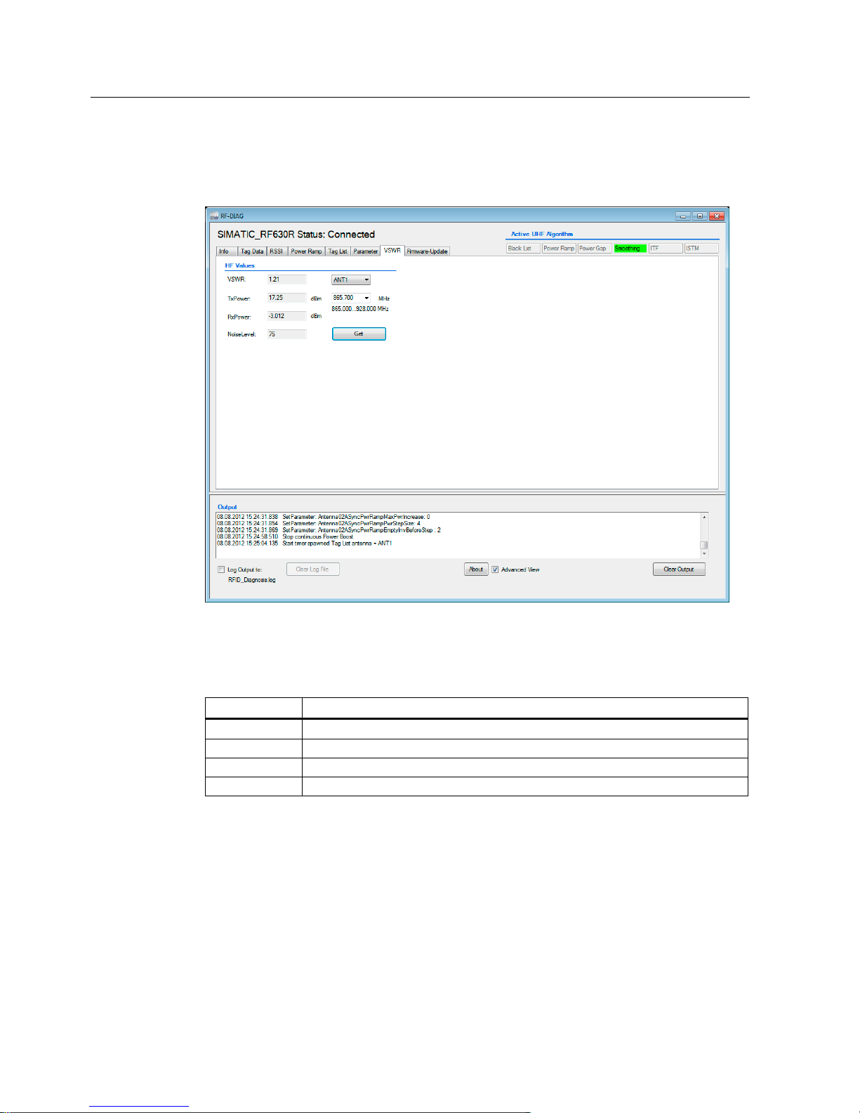
Operating the software
5.4 The tabs of the RF620R/RF630R readers
SIMATIC RF-DIAG
62 Operating Manual, 09/2012, C79000-G8976-C292-01
5.4.7 The "VSWR" tab
With the "VSWR" tab, you can read out HF values, quality characteristics of the air interface.
Figure 5-14 The "VSWR" tab
The HF Values
Parameter Description
VSWR Voltage standing wave ratio: Is calculated from Tx and Rx Power. *)
Tx Power Power at output in [dBm]
Rx Power Power at input in [dBm]
Noise Level Noise level: Wideband RSSI value measured by reader
*) A value ≥ 1.5 may indicate a hardware defect. Contact Customer Support in this case.
From the upper drop-down list, you can select the antenna with which you want to read out
the HF values. From the lower drop-down list, you can select the frequency range of the
antenna. If the frequency you require cannot be selected, you can also enter this value. You
will find the frequency bands of the various reader types in the following table:
Page 63

Operating the software
5.4 The tabs of the RF620R/RF630R readers
SIMATIC RF-DIAG
Operating Manual, 09/2012, C79000-G8976-C292-01
63
Reader type Frequency band
ETSI 865,7 ... 867.5 MHz
FCC USA: 902 ... 928 MHz
Brazil: 515,25 ... 527.75 MHz
South Korea: 917,3 ... 920.3 MHz
CMIIT 920,125 ... 924.875 MHz
Click the "Read" button to read out the HF values of the selected antenna.
Page 64
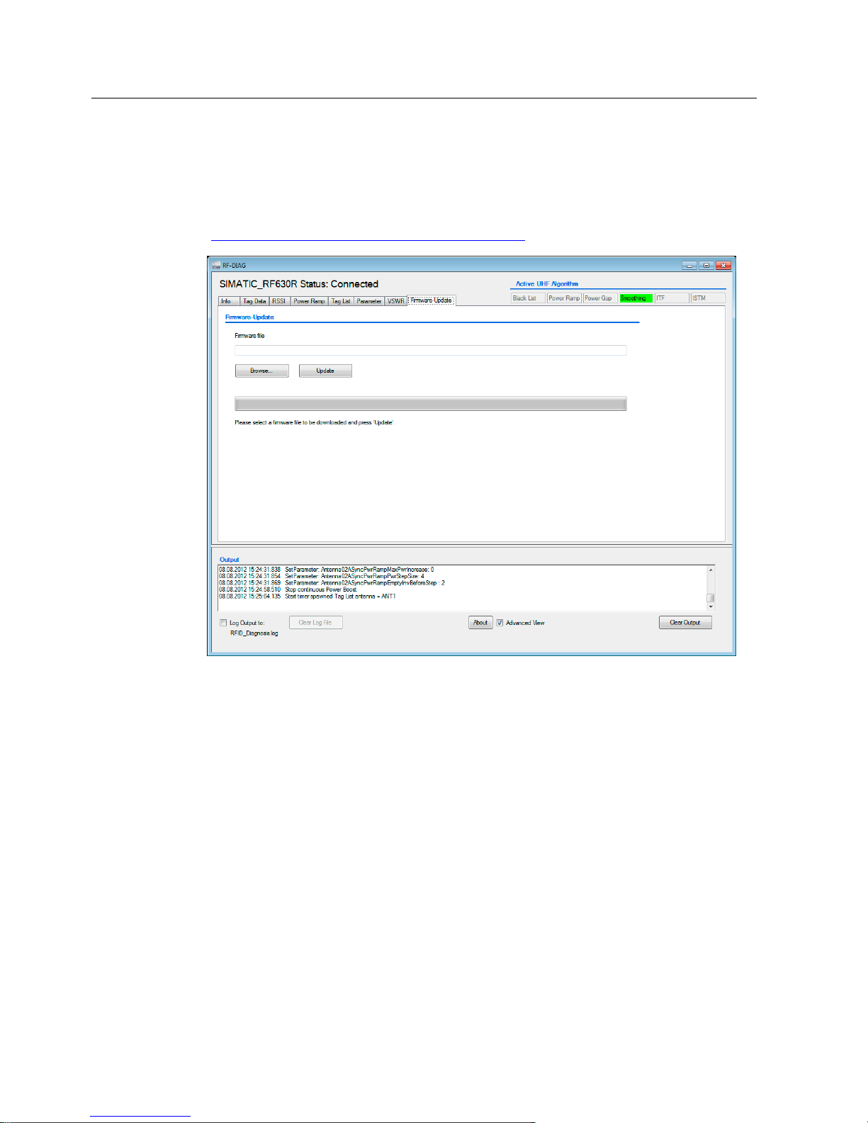
Operating the software
5.4 The tabs of the RF620R/RF630R readers
SIMATIC RF-DIAG
64 Operating Manual, 09/2012, C79000-G8976-C292-01
5.4.8 The "Firmware-Update" tab
With the "Firmware-Update" tab, you can update the firmware of the serial RF600 readers
(RF620R/RF630R). You will find more detailed information on the firmware in the section
"Service & Support (Page 79)" and on the Internet on the "Support homepage
(http://www.siemens.com/automation/service&support
)".
Figure 5-15 The "Firmware-Update" tab
To update the firmware, proceed as follows:
1. Copy the update file to your PC or programming device.
2. Select the update file.
You can enter the path of the update five in the input box or select the update file using
the "Browse..." button.
3. Click the "Update" button to start the update.
Reaction: The update is started and the update progress is shown.
Reaction: Following a successful update, the "Info" tab is opened automatically.
Page 65
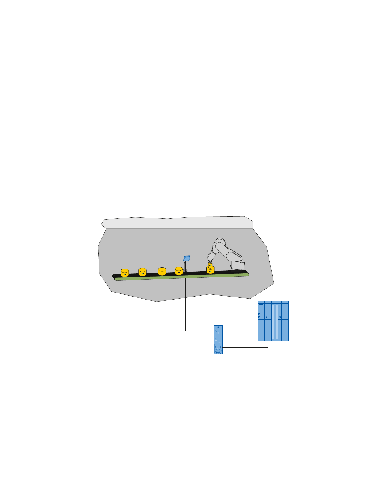
SIMATIC RF-DIAG
Operating Manual, 09/2012, C79000-G8976-C292-01
65
Application Examples
6
6.1 Scenarios for use of the PC adapter for RF-DIAG
SIMATIC RF-DIAG can be used in conjunction with the PC adapter in two different
scenarios:
● "Operation in the plant"
● "Operation in a test setup"
Operation in the plant
SIMATIC RF-DIAG is used to set up, assign parameters to or diagnose an RF620R/RF630R
reader installed in the plant.
The RF620R/RF630R reader is installed in the plant and connected to a communications
module.
6,0$7,&6
FRQWUROOHU
&0
Figure 6-1 Operating a serial reader in the plant
The PC adapter for RF-DIAG is now inserted between the communications module and
reader and the sequence is restarted in the plant. As long as no PC is connected to the
adapter via USB, communication between the communications module and reader remains
unaffected. The adapter does not disrupt operation. As soon as a PC is connected to the
adapter via USB, communication from the reader is redirected to the PC. The power supply
of the reader via the communications module is not interrupted. No separate power supply is
necessary.
Page 66
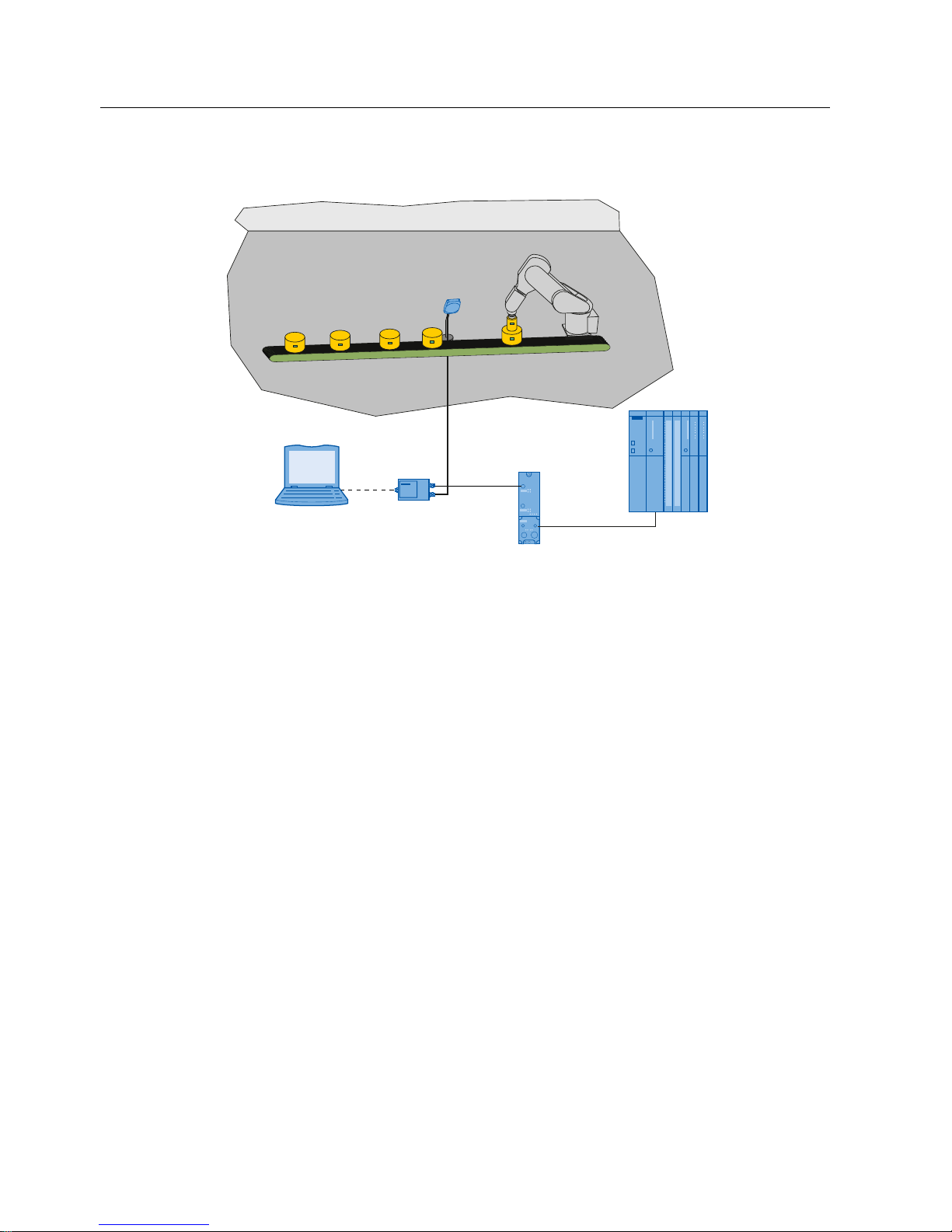
Application Examples
6.1 Scenarios for use of the PC adapter for RF-DIAG
SIMATIC RF-DIAG
66 Operating Manual, 09/2012, C79000-G8976-C292-01
3*3&
3&DGDSWHU
6,0$7,&6
FRQWUROOHU
&0
Figure 6-2 Operating a serial reader in the plant with connected PC adapter
After completing the tasks with RF-DIAG, restarting the reader and unplugging the USB
cable, the connection between the reader and communications module is restored. A
subsequent "init_run" command changes the reader to the required operational status.
Operation in a test setup
SIMATIC RF-DIAG is used to test, assign parameters to or diagnose an RF620R/RF630R
reader outside the plant.
The RF620R/RF630R is connected to the PC adapter. The PC with RF-DIAG is connected
to the PC adapter via USB. To supply the reader with power, the wide-range power supply
unit is connected to the PC adapter via the connecting cable.
The following application examples are based one on the other. It is advisable to read
through the application examples in the order in which they appear.
Page 67

Application Examples
6.2 Example of an application "optimize antenna position"
SIMATIC RF-DIAG
Operating Manual, 09/2012, C79000-G8976-C292-01
67
6.2 Example of an application "optimize antenna position"
Aim
The aim is to find the optimum antenna position of an RFID reading point as quickly as
possible. A good antenna position should have a high and stable RSSI value.
Background
The position and alignment of the RFID antennas has a significant influence on the quality of
the read results. For this reason, mounting the antennas is an important step during
commissioning of an RFID reading point. With SIMATIC RF-DIAG it is possible to find the
optimum antenna position and alignment simply and quickly.
The strength of the transponder reply is known as the RSSI value (Received Signal Strength
Indication). The RSSI value can be between 0 and 255. The higher the RSSIvalue, the better
the signal strength. The actual value depends on numerous parameters including the
transponder type, the chip used in the transponder, antenna, transmit power, distance
between antenna and transponder, reflections, noise level in the channels used and in
neighboring channels etc.
In practice, RSSI values of approximately 65 to approximately 115 can be detected with
SIMATIC RF600 readers.
Procedure
1. Mount the antenna in its approximate position at the selected installation location.
2. Then connect the reader to the commissioning PC with RF-DIAG via the PC adapter and
select the "RSSI" tab in the tool.
3. Create a typical identification situation. In other words, position the object including the
transponder at the point at which it needs to be identified later during operation.
Note
Make sure there is line-of-sight contact between the antenna and transponder
Make sure that there are no persons or objects between the antenna and the transponder
and that the neighboring antenna fields are deactivated that could otherwise disturb
transmission.
4. Set the transmit power to level 0. When necessary, deactivate all additional functions
(Power Ramp, Black List, ITF, Tag Hold, RSSI Threshold etc.). In the factory setting,
these are deactivated.
Page 68

Application Examples
6.2 Example of an application "optimize antenna position"
SIMATIC RF-DIAG
68 Operating Manual, 09/2012, C79000-G8976-C292-01
5. By adjusting the antenna or transponder horizontally or vertically and by adapting the
angle of inclination, find the position at which the highest RSSI value is displayed in the
diagnostics tool.
The display of the RSSI value is indicated in a large font and can therefore be read at the
distance of several meters. A good antenna position results in a high and stable RSSI
value.
If the transponder cannot be identified at any position, increase the transmit power by one
level and repeat step 5.
6. Once you have found the optimum position secure the antenna in this position.
Possible error symptoms and how to counter them
Error symptom 1:
Despite optimization measures, the transponder data cannot be read out regularly.
Countermeasure 1:
Select an adequately high transmit power (see example "Example of an application
"Determi
ning transmit power" (Page 69)") and optimize this, if nece
ssary using further UHF
algorithms.
Error symptom 2:
Despite adapting the transmit power, the transponder data cannot be read out regularly.
Countermeasure 2:
Optimizing the reading point:
● Antenna position and alignment
● Transponder alignment
● possibly use of absorption materials
Further options open to you include the choice of alternative antennas or the use of multiple
antennas for a reading point (diversity).
You will find further information on the set and achievable distances in the section "RF600
system planning" in the "RF600 system manual
(http://support.automation.siemens.
com/WW/view/en/22437600)".
Page 69

Application Examples
6.3 Example of an application "Determining transmit power"
SIMATIC RF-DIAG
Operating Manual, 09/2012, C79000-G8976-C292-01
69
6.3 Example of an application "Determining transmit power"
Aim
The aim is to find the minimum transmit power with which a transponder can be identified.
Background
The "Power Ramp" function of the RF620R and RF630R readers allows the reader to
increase the transmit power automatically if no transponder is identified in the field. This
function can be used to obtain the power settings of a reading point.
Procedure
Requirements:
The reading point is fully installed and the reader is connected to the SIMATIC RF-DIAG tool
via the PC adapter. Make sure that you make changes to the values of the Power Ramp
based on real environmental conditions.
1. Select the "Power Ramp" tab in SIMATIC RF-DIAG. You will find a precise description of
the Power ramp algorithm in the relevant section of the "SIMATIC RF620R/RF630R
Configuration Manual (http://support.automation.siemens.com/WW/
view/en/33287195)".
2. Make the settings for the Power Ramp as follows:
– For each antenna to be used, select a low power limit (corresponds to ANT1:
RESET[distance_limiting, bit 0-3] and ANT2: RESET[distance_limiting, bit 4-7])
– Select a power increase per step (Boost Step Size ANT1, Boost Step Size ANT2)
– Select the maximum power increase to be reached after n steps (Boost Max ANT1,
Boost Max ANT2)
– Select the number of consecutive inventories to be taken via ANT1 or ANT2 before
the power is increased by a step (Boost Threshold ANT1, Boost Threshold ANT2)
– The Power Ramp remains at the transmit power at which the transponder was
identified.
If the parameter settings for the setup have been optimized, the required power is selected
automatically by the algorithm to perform transponder inventories. After several runs, the
necessary power for identifying the transponders reaches a maximum value between the
Power Ramp low limit and the Power Ramp high limit.
Adopt the power settings in SIMATIC RF-DIAG in the PLC or STEP 7 application:
● By selecting the achieved maximum power for ANT1 using RESET[distance_limiting, bit
0-3] and for ANT2 using, RESET[distance_limiting, bit 4-7], it is possible to ensure
identification of the transponder.
● By using the Power Ramp algorithm set here, situation-specific adaptation of the power is
possible.
Page 70

Application Examples
6.3 Example of an application "Determining transmit power"
SIMATIC RF-DIAG
70 Operating Manual, 09/2012, C79000-G8976-C292-01
Note
Maximum transmit power is limited by the hardware
Remember that the maximum achievable transmit power is limited physically by the reader.
When using the Power Ramp, remember to include already active UHF algorithms that affect
the transmit power (Read/Write Boost). The maximum physical transmit power cannot be
exceeded.
Possible error symptoms and how to counter them:
Error symptom 1:
The power setting usually has a value close to or identical to the set Power Ramp high limit.
Countermeasure 1:
Increase the Power Ramp high limit. If this is not possible, modify the antenna configuration
(see example "Example of an application "optimize a
ntenna position" (Page 67)") or select a
different antenna.
Error symptom 2:
The Power Ramp low limit is not adequate to identify the transponders. Too many steps are
required to reach the necessary power.
Countermeasure 2:
Increase the Power Ramp low limit and, if necessary the step size (Boost Step Size ANT1 or
Boost Step Size ANT2).
Page 71

Application Examples
6.4 Example of an application "Setting the Power Ramp and RSSI Threshold"
SIMATIC RF-DIAG
Operating Manual, 09/2012, C79000-G8976-C292-01
71
6.4 Example of an application "Setting the Power Ramp and RSSI
Threshold"
Aim
The aim is to increase the robustness of the reading point by using the Power Ramp in read
mode and using the RSSI Threshold to avoid overshoot.
Background
The Power Ramp algorithm is useful when a transponder needs to be identified with an
output power as low as possible (inventory). This power can vary by several dB between
inventories taken at different times.
The use of an RSSI threshold is a practical solution when an RSSI value is detected at a
reading point for the transponders to be identified that is always higher than the minimum
value (RSSI Threshold) and other transponders outside the reading point are always below
this threshold.
Procedure
To evaluate an optimized parameter assignment of Power Ramp and RSSI Threshold, use
the "Tag List" tab. Use the "RSSI" tab to assign the RSSI threshold values (RSSI Threshold
ANT1, RSSI Threshold ANT2). To make settings for Power Ramp, use the "Power Ramp"
tab.
The following values have proved useful in typical use cases:
● Monitor the RSSI values of the transponders in the Tag List. Note down the typical RSSI
value of the required transponder (overreach). Set the value of RSSI Threshold ANT1 /
RSSI Threshold ANT2 half way between the two obtained values. In many situations, this
results in an RSSI Threshold of approximately 88% of the RSSI value of the required
transponder.
● Set Boost Max ANT1 / Boost Max ANT2 to 8 (+2 dB), Boost Step Size ANT1 / Boost Step
Size ANT2 to 4 (1 dB) and Boost Threshold ANT1 / Boost Threshold AN2 to 2 (2
inventories).
Page 72

Application Examples
6.4 Example of an application "Setting the Power Ramp and RSSI Threshold"
SIMATIC RF-DIAG
72 Operating Manual, 09/2012, C79000-G8976-C292-01
Note
Ensuring data access reliability
It is advisable to include a recording of SLG-STATUS and MDS-STATUS during operation in
the PLC or STEP 7 application. With the help of the data, you can evaluate and ensure data
access reliability during read/write access to various transponders. If the result is
satisfactory, follow the steps below:
• Adapt the RSSI Threshold more accurately to the actual situation based on the actually
measured RSSI values.
• Adjust the transmit power. If the actual transmit power is regularly higher than the set
transmit power, the Power Ramp will be active often. This is an indication that the basic
transmit power is too low.
Adapting the Power Ramp:
If the transmit power goes up to the higher power value in at least 25% of the reads (actual
transmit power = basic power + Power Ramp value) the Power Ramp is set somewhat too
low or has too little power reserve. Here, it is advisable to increase the Power Ramp. The
procedure is analogous to "Example of an application "Determining transmit power"
(Page 69)".
If a s
uitable parameter assignment was selected for the setup, a suitable power will be
selected in an adequately short time by the algorithm to be able to take inventories of the
transponders and transponders that should not be identified can be rejected by the RSSI
filter. After several runs, the necessary power for identifying the transponders reaches a
maximum value between the Power Ramp low limit and the Power Ramp high limit.
Possible error symptoms and how to counter them
Error symptom 1:
Optimization measures do not lead to successful data access often enough.
Countermeasure 1:
Select an adequately high transmit power (see example "Example of an application
"Determi
ning transmit power" (Page 69)") and optimize this, if nece
ssary using further UHF
algorithms.
Error symptom 2:
Despite adjusting the transmit power, the antenna position cannot be optimized.
Countermeasure 2:
Optimize the RSSI thresholds. If this measure is not successful, optimization by using further
UHF algorithms (e.g. ISTM) may bring about improvements.
Optimize the reading point. Further options open to you include the choice of alternative
antennas or the use of multiple antennas for a reading point (diversity).
Page 73

Application Examples
6.4 Example of an application "Setting the Power Ramp and RSSI Threshold"
SIMATIC RF-DIAG
Operating Manual, 09/2012, C79000-G8976-C292-01
73
Error symptom 3:
The power setting usually has a value close to or identical to the set Power Ramp high limit.
Countermeasure 3:
Increase the Power Ramp high limit. If this is not possible, modify the antenna configuration
(see example Example of an application "optimize a
ntenna position" (Page 67)) or select a
different antenna.
Error symptom 4:
The Power Ramp low limit is never adequate to identify the transponders. Too many steps
are required to reach the necessary power.
Countermeasure 4:
Increase the Power Ramp low limit and, if necessary the step size (Boost Step Size ANT1 or
Boost Step Size ANT2).
Page 74
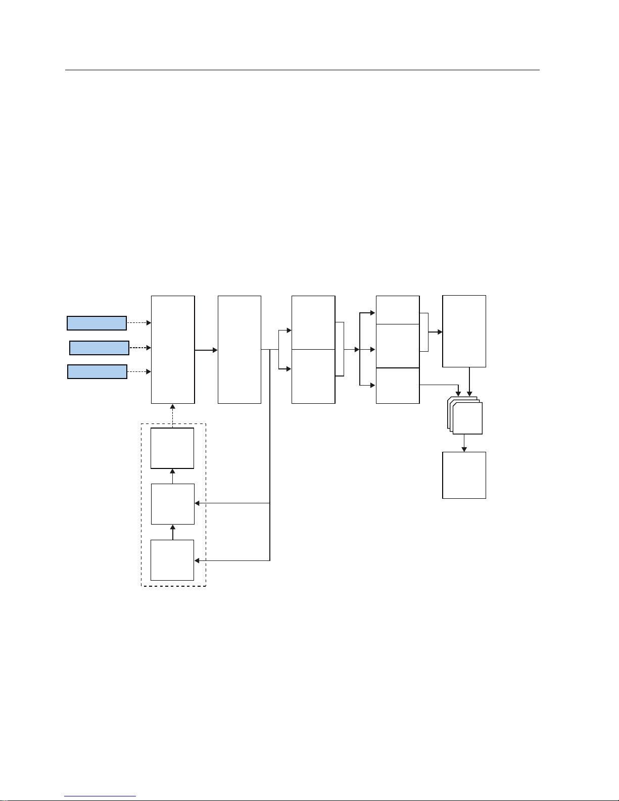
Application Examples
6.5 Example of an application "Testing and setting parameters for industrial UHF algorithms"
SIMATIC RF-DIAG
74 Operating Manual, 09/2012, C79000-G8976-C292-01
6.5 Example of an application "Testing and setting parameters for
industrial UHF algorithms"
Aim
The aim is to test whether the behavior of the reading point can be improved by the use of
industrial UHF algorithms and to find the optimum parameter settings for them.
Background
If antenna optimization and the Power Ramp do not lead to a satisfactory result, further
industrial algorithms need to be activated:
7$*,'
&ROOHFW
,QYHQWRU\
%ODFN/LVW
7$*,'
7$*,'
6PRRWKLQJ
,QYHQWRU\
7KUHVKROG
)LOWHU
6LQJOHWDJ
,QWHOOLJHQW
6LQJOHWDJ
0RGH
0XOWLWDJ
7DJ + ROG
6
,QWHUIDFH
3RZHU
5DPS
5DGLR3RZHU
3RZHU
*DS
7DJ /LVW
5HDG
%RRVW
:ULWH
%RRVW
Figure 6-3 Tag List Processing by the industrial SIMATIC UHF algorithms of the RF600 reader
Page 75

Application Examples
6.5 Example of an application "Testing and setting parameters for industrial UHF algorithms"
SIMATIC RF-DIAG
Operating Manual, 09/2012, C79000-G8976-C292-01
75
Brief description of the UHF algorithms:
● Black List: Filtering out of transponders that have already been processed
● Smoothing:Filtering if transponders are not constantly detectable
● Inventory Threshhold Filter: Filtering of transponders based on their read frequency
● Intelligent Singletag Mode: Automatic selection of a transponder based on its properties
in the wireless field
● Tag Hold: Reliable process access to a transponder that has already been processed
● Power Ramp: Automatic adaptation of the transmit power
● Power Gap: Improved interference immunity when operating readers installed close
together
● Read/Write Boost: Increased power when reading and writing transponders
This results in the following options for combining filters:
Table 6- 1 Possible combinations of the UHF algorithms
Operating mode Read/Write
Boost
Power Ramp /
Power Gap
Black List ISTM
1)
Tag Hold
Smoothing
Single tag mode
X X X X X
Smoothing
Multitag mode
X X X - -
ITF
Single tag mode
X X X X X
ITF
Multitag mode
X X X - -
1)
Intelligent Singletag Mode
You will find further details on the algorithms in section 6.3 in Parameter assignment manual
RF620R/RF630R (http://support.automation.siemens.
com/WW/view/en/33287195).
The parameters to be used here are displayed in the "Parameter" tab and can be adapted
there and stored directly on the reader. The meaning of the parameters is also described in
section 6.3 of the Parameter assignment manual RF620R/RF630R
(http://support.automation.siemens.
com/WW/view/en/33287195).
The tag list events are visualized in the "Tag List" tab.
Procedure
When deciding which algorithms need to be activated, we suggest the following procedure:
For single tag mode:
1. Optimize the antenna configuration (see Example of an application "optimize antenna
positio
n" (Page 67)) including the RSSI Threshold.
2. Set the para
meters for the Power Gap and the Power Ramp and optimize.
Page 76

Application Examples
6.5 Example of an application "Testing and setting parameters for industrial UHF algorithms"
SIMATIC RF-DIAG
76 Operating Manual, 09/2012, C79000-G8976-C292-01
3. Set the parameters for Read Boost /Write Boost and optimize them if the inventories are
very successful but the reads and writes are less reliable.
4. Set parameters for the Black List filter and optimize them.
5. Decide whether parameter assignment and optimization of inventories should be filtered
using Smoothing or ITF so that these can then have parameters assigned and be
optimized.
6. Decide whether single tag mode or Intelligent Singletag Mode (ISTM) and Sorting are
necessary to be able to assign parameters and optimize ISTM later.
7. Decide whether Tag Hold should also be activated if the inventories return good tag
identification but subsequent reads and writes are less often successful and a
permanently set Read Boost /Write Boost with the required power increase leads to too
much interference in the plant.
Since all algorithms are dependent on each other, steps 1 to 7 may need to be worked
through several times.
For multitag mode:
1. Optimize the antenna configuration (see Example of an application "optimize antenna
positio
n" (Page 67)) including the RSSI Threshold.
2. Set the para
meters for the Power Gap and the Power Ramp and optimize.
3. Set the parameters for Read Boost /Write Boost and optimize them if the inventories are
very successful but the reads and writes are less reliable.
4. Set parameters for the Black List filter and optimize them.
Since all algorithms are dependent on each other, steps 1 to 4 may need to be worked
through several times.
If the parameter assignment for the setup was selected suitably, the suitable power will be
selected by the algorithm in an adequately short time to be able to take inventories of the
transponders. The transponders that cannot be identified are discarded by the RSSI filter.
Read and write access is always to the required transponder with the required Read/Write
Boost or Tag Hold.
Possible error symptoms and how to counter them
The possible error symptoms result from the data access statistics of each separate step (1
to 7) achieved for the application. The countermeasures for each error are listed for steps 1
and 2.
For each of the steps 3 to 7, the countermeasure is to set the parameters of each parameter
set and optimize them. You are supported by a log file and the "Tag List" tab allowing you to
evaluate the parameter assignment of all the parameters.
Page 77

SIMATIC RF-DIAG
Operating Manual, 09/2012, C79000-G8976-C292-01
77
Error and system messages
7
Fault messages
Error message Note
ERROR: Windows Environment Variable "TZ={0}" found!
Tool will calculate wrong time stamps!
Delete the variable.
ERROR: weak power Increase the power.
Page 78

Error and system messages
SIMATIC RF-DIAG
78 Operating Manual, 09/2012, C79000-G8976-C292-01
Page 79

SIMATIC RF-DIAG
Operating Manual, 09/2012, C79000-G8976-C292-01
79
Appendix A
A
A.1 Service & Support
Contacts
If you have any further questions on the use of our products, please contact one of our
representatives at your local Siemens office.
The addresses are found on the following pages:
● On the Contact partner (www.siemens.com/automation/partner
)
● In Catalog CA 01
● In Catalog ID 10 specifically for industrial communication / industrial identification systems
Technical Support
You can access technical support for all IA/DT projects via the following:
● Phone: + 49 (0) 911 895 7222
● Fax: + 49 (0) 911 895 7223
● E-mail (mailto:[email protected]
)
● Internet: Online support request form: (www.siemens.com/automation/su
pport-request)
Service & support for industrial automation and drive technologies
You can find various services on the Support homepage
(www.siemens.com/automation/service&support
) of IA/DT on the Internet.
There you will find the following information, for example:
● Our newsletter containing up-to-date information on your products.
● Relevant documentation for your application, which you can access via the search
function in "Product Support".
● A forum for global information exchange by users and specialists.
● Your local contact for IA/DT on site.
● Information about on-site service, repairs, and spare parts. Much more can be found
under "Our service offer".
RFID homepage
For general information about our identification systems, visit RFID homepage
(http://www.siemens.com/ident/rfid
).
Page 80

Appendix A
A.1 Service & Support
SIMATIC RF-DIAG
80 Operating Manual, 09/2012, C79000-G8976-C292-01
Technical documentation on the Internet
A guide to the technical documentation for the various products and systems is available on
the Internet:
SIMATIC Guide manuals (www.siemens.com/simatic-tech-doku-portal
)
Online catalog and ordering system
The online catalog and the online ordering system can also be found on the Industry Mall
Homepage (http://www.siemens.de/industrial-controls/mall
).
Training center
We offer appropriate courses to get you started. Please contact your local training center or
the central training center in
D-90327 Nuremberg.
Phone: +49 (0) 180 523 56 11
(€ 0.14 /min. from the German landline network, deviating mobile communications prices are
possible)
For information about courses, see the SITRAIN homepage (www.sitrain.com
).
 Loading...