

Page 1

SIMATIC RF650R/RF680R/RF685R
___________________
___________________
___________________
___________________
___________________
___________________
___________________
___________________
___________________
___________________
SIMATIC Ident
RFID systems
SIMATIC
RF650R/RF680R/RF685R
Configuration Manual
10/2015
C79000
Introduction
1
Notes on security
2
Description
3
Commissioning
4
Configuration via STEP 7
(PROFINET device)
5
Configuring with the WBM
6
Interface to the SIMATIC
controller
7
XML interface
8
Service and maintenance
9
Appendix
A
-G8976-C386-03
Page 2

Siemens AG
Division Process Industries and Drives
Postfach 48 48
90026 NÜRNBERG
GERMANY
C79000-G8976-C386-03
Ⓟ
Copyright © Siemens AG 2014 - 2015.
All rights reserved
Legal information
Warning notice system
DANGER
indicates that death or severe personal injury will result if proper precautions are not taken.
WARNING
indicates that death or severe personal injury may result if proper precautions are not taken.
CAUTION
indicates that minor personal injury can result if proper precautions are not taken.
NOTICE
indicates that property damage can result if proper precautions are not taken.
Qualified Personnel
personnel qualified
Proper use of Siemens products
WARNING
Siemens products may only be used for the applications described in the catalog and in the relevant technical
maintenance are required to ensure that the products operate safely and without any problems. The permissible
ambient conditions must be complied with. The information in the relevant documentation must be observed.
Trademarks
Disclaimer of Liability
This manual contains notices you have to observe in order to ensure your personal safety, as well as to prevent
damage to property. The notices referring to your personal safety are highlighted in the manual by a safety alert
symbol, notices referring only to property damage have no safety alert symbol. These notices shown below are
graded according to the degree of danger.
If more than one degree of danger is present, the warning notice representing the highest degree of danger will
be used. A notice warning of injury to persons with a safety alert symbol may also include a warning relating to
property damage.
The product/system described in this documentation may be operated only by
task in accordance with the relevant documentation, in particular its warning notices and safety instructions.
Qualified personnel are those who, based on their training and experience, are capable of identifying risks and
avoiding potential hazards when working with these products/systems.
Note the following:
documentation. If products and components from other manufacturers are used, these must be recommended
or approved by Siemens. Proper transport, storage, installation, assembly, commissioning, operation and
All names identified by ® are registered trademarks of Siemens AG. The remaining trademarks in this publication
may be trademarks whose use by third parties for their own purposes could violate the rights of the owner.
We have reviewed the contents of this publication to ensure consistency with the hardware and software
described. Since variance cannot be precluded entirely, we cannot guarantee full consistency. However, the
information in this publication is reviewed regularly and any necessary corrections are included in subsequent
editions.
for the specific
10/2015 Subject to change
Page 3

Table of contents
1 Introduction ............................................................................................................................................. 7
2 Notes on security .................................................................................................................................... 9
3 Description ............................................................................................................................................ 11
4 Commissioning ..................................................................................................................................... 17
5 Configuration via STEP 7 (PROFINET device) ...................................................................................... 29
6 Configuring with the WBM ..................................................................................................................... 33
1.1 Preface ...................................................................................................................................... 7
1.2 Abbreviations and naming conventions .................................................................................... 8
3.1 Properties of the UHF readers ................................................................................................ 11
3.2 User-specific procedures ........................................................................................................ 14
4.1 Important notes on using the device ....................................................................................... 17
4.2 Connect the hardware............................................................................................................. 19
4.3 Setup/network topology .......................................................................................................... 21
4.4 Assign the IP address / device name ..................................................................................... 22
4.4.1 Assigning the IP address / device name with the PST ........................................................... 23
4.4.2 Assigning the IP address / device name with STEP 7 ............................................................ 25
5.1 Linking readers into STEP 7 (Basic / Professional) ................................................................ 29
5.2 The TIA Portal (STEP 7 Basic / Professional) ........................................................................ 30
5.3 Overview of the configurable properties ................................................................................. 31
6.1 Starting WBM .......................................................................................................................... 33
6.2 The WBM ................................................................................................................................ 35
6.3 The menu items of the WBM .................................................................................................. 40
6.3.1 The "Start page" menu item .................................................................................................... 40
6.3.2 The "Settings - General" menu item ....................................................................................... 42
6.3.3 The "Settings - Read points" menu item ................................................................................. 46
6.3.4 The "Settings - Tag fields" menu item .................................................................................... 58
6.3.5 The "Settings - Filters" menu item .......................................................................................... 60
6.3.6 The "Settings - Digital outputs" menu item ............................................................................. 64
6.3.7 The "Settings - Communication" menu item ........................................................................... 66
6.3.8 The "Settings - Adjust antenna" menu item ............................................................................ 71
6.3.9 The "Settings - Activation power" menu item .......................................................................... 73
6.3.10 The "Diagnostics - Tag monitor" menu item ........................................................................... 77
6.3.11 The "Diagnostics - Log" menu item ........................................................................................ 80
6.3.12 The "Diagnostics - Messages" menu item .............................................................................. 82
6.3.13 The "Edit transponder" menu item .......................................................................................... 83
6.3.14 The "User management" menu item ....................................................................................... 87
6.3.15 The "System" menu item ........................................................................................................ 91
SIMATIC RF650R/RF680R/RF685R
Configuration Manual, 10/2015, C79000-G8976-C386-03
3
Page 4

Table of contents
7 Interface to the SIMATIC controller ....................................................................................................... 93
8 XML interface ...................................................................................................................................... 139
6.3.16 The "Help" menu item ............................................................................................................ 92
7.1 Retrieving the Ident library ..................................................................................................... 93
7.2 Overview of the Ident library .................................................................................................. 94
7.3 Project preparations ............................................................................................................... 95
7.4 Setting the "IID_HW_CONNECT" data type .......................................................................... 97
7.5 General structure of the function blocks ................................................................................ 99
7.6 Programming Ident blocks ................................................................................................... 103
7.6.1 Basic blocks ......................................................................................................................... 103
7.6.1.1 Read ..................................................................................................................................... 103
7.6.1.2 Reset_Reader ...................................................................................................................... 104
7.6.1.3 Write ..................................................................................................................................... 104
7.6.2 Extended blocks ................................................................................................................... 106
7.6.2.1 Config_Upload/-_Download ................................................................................................. 106
7.6.2.2 Inventory .............................................................................................................................. 109
7.6.2.3 Read_EPC_Mem.................................................................................................................. 113
7.6.2.4 Read_TID ............................................................................................................................. 114
7.6.2.5 Set_Param ........................................................................................................................... 115
7.6.2.6 Write_EPC_ID ...................................................................................................................... 117
7.6.2.7 Write_EPC_Mem .................................................................................................................. 118
7.6.2.8 AdvancedCMD ..................................................................................................................... 119
7.6.3 Status blocks ........................................................................................................................ 120
7.6.3.1 Reader_Status ..................................................................................................................... 120
7.7 Programming the Ident profile .............................................................................................. 121
7.7.1 Structure of the Ident profile ................................................................................................. 121
7.7.2 Overview of the commands .................................................................................................
123
7.7.3 Command structure ............................................................................................................. 124
7.7.4 Commands ........................................................................................................................... 126
7.7.5 Chaining ............................................................................................................................... 130
7.7.6 Command repetition ............................................................................................................. 132
7.8 Digital inputs/outputs ............................................................................................................ 138
8.1 Functionality of the XML interface........................................................................................ 139
8.2 Demo application ................................................................................................................. 141
8.2.1 Structure of the demo application ........................................................................................ 141
8.2.2 User interface of the demo application ................................................................................ 143
8.2.3 Working with the demo application ...................................................................................... 144
8.3 XML commands ................................................................................................................... 145
8.3.1 Connections ......................................................................................................................... 146
8.3.1.1 hostGreetings ....................................................................................................................... 147
8.3.1.2 hostGoodbye ........................................................................................................................ 148
8.3.1.3 heartBeat .............................................................................................................................. 149
8.3.2 Reader settings .................................................................................................................... 150
8.3.2.1 setConfiguration ................................................................................................................... 150
8.3.2.2 getConfiguration ................................................................................................................... 151
8.3.2.3 getConfigVersion.................................................................................................................. 152
SIMATIC RF650R/RF680R/RF685R
4 Configuration Manual, 10/2015, C79000-G8976-C386-03
Page 5

Table of contents
9 Service and maintenance .................................................................................................................... 225
8.3.2.4 getActiveConfiguration .......................................................................................................... 153
8.3.2.5 getLogfile .............................................................................................................................. 154
8.3.2.6 resetLogfile ........................................................................................................................... 155
8.3.2.7 setParameter ........................................................................................................................ 156
8.3.2.8 getParameter ........................................................................................................................ 158
8.3.2.9 setTime ................................................................................................................................. 160
8.3.2.10 getTime ................................................................................................................................. 161
8.3.2.11 setIO...................................................................................................................................... 162
8.3.2.12 getIO ..................................................................................................................................... 164
8.3.2.13 resetReader .......................................................................................................................... 165
8.3.2.14 getReaderStatus ................................................................................................................... 167
8.3.3 Transponder processing ....................................................................................................... 168
8.3.3.1 editBlackList .......................................................................................................................... 169
8.3.3.2 getBlackList ........................................................................................................................... 170
8.3.3.3 getAllSources ........................................................................................................................ 172
8.3.3.4 triggerSource ........................................................................................................................ 173
8.3.3.5 readTagIDs ........................................................................................................................... 174
8.3.3.6 getObservedTagIDs .............................................................................................................. 177
8.3.3.7 writeTagID ............................................................................................................................. 181
8.3.3.8 readTagMemory .................................................................................................................... 185
8.3.3.9 writeTagMemory ................................................................................................................... 189
8.3.3.10 readTagField ......................................................................................................................... 194
8.3.3.11 writeTagField ........................................................................................................................
198
8.3.3.12 killTag .................................................................................................................................... 202
8.3.3.13 lockTagBank ......................................................................................................................... 206
8.3.4 Negative XML replies ............................................................................................................ 211
8.4 XML EventReports ................................................................................................................ 214
8.4.1 Events ................................................................................................................................... 214
8.4.1.1 tagEventReport ..................................................................................................................... 214
8.4.1.2 rssiEventReport .................................................................................................................... 218
8.4.1.3 ioEventReport ....................................................................................................................... 220
8.4.2 Interrupts ............................................................................................................................... 222
9.1 Diagnostics ........................................................................................................................... 225
9.1.1 Diagnostics via the LED displays .......................................................................................... 226
9.1.2 Diagnostics via display elements .......................................................................................... 228
9.1.3 Diagnostics via SNMP .......................................................................................................... 229
9.1.4 Diagnostics using the WBM .................................................................................................. 229
9.1.5 Diagnostics using the TIA Portal (STEP 7 Basic / Professional) .......................................... 230
9.2 Error messages ..................................................................................................................... 232
9.2.1 How the LED status display works ....................................................................................... 233
9.2.2 RF650R/RF680R/RF685R error messages.......................................................................... 234
9.3 Module replacement ............................................................................................................. 240
9.3.1 Backup configuration data .................................................................................................... 240
9.3.2 Replacing a module .............................................................................................................. 243
9.4 Firmware update ................................................................................................................... 244
9.5 Restore to factory settings .................................................................................................... 245
SIMATIC RF650R/RF680R/RF685R
Configuration Manual, 10/2015, C79000-G8976-C386-03
5
Page 6

Table of contents
A Appendix ............................................................................................................................................. 247
A.1 Planning and installation of UHF read points ....................................................................... 247
A.1.1 Technical basics................................................................................................................... 247
A.1.2 Implementation of UHF RFID installations ........................................................................... 250
A.1.2.1 Preparation phase ................................................................................................................ 250
A.1.2.2 Test phase ........................................................................................................................... 252
A.1.2.3 Setting up read points .......................................................................................................... 252
A.1.3 Dealing with field disturbances ............................................................................................ 256
A.1.3.1 Types and approaches to solutions ..................................................................................... 256
A.1.3.2 Measures for eliminating field disturbances ......................................................................... 258
A.2 Command and acknowledgement frames ........................................................................... 260
A.2.1 Structure of the command frame ......................................................................................... 260
A.2.2 READER-STATUS ............................................................................................................... 261
A.2.3 INVENTORY ........................................................................................................................ 262
A.2.4 PHYSICAL-READ ................................................................................................................ 263
A.2.5 PHYSICAL-WRITE............................................................................................................... 264
A.2.6 WRITE-ID ............................................................................................................................. 265
A.2.7 KILL-TAG ............................................................................................................................. 266
A.2.8 LOCK-TAG-BANK ................................................................................................................ 267
A.2.9 EDIT-BLACKLIST ................................................................................................................ 268
A.2.10 GET-BLACKLIST ................................................................................................................. 269
A.2.11 READ-CONFIG .................................................................................................................... 270
A.2.12 WRITE-CONFIG .................................................................................................................. 271
A.3 Service & Support ................................................................................................................
272
SIMATIC RF650R/RF680R/RF685R
6 Configuration Manual, 10/2015, C79000-G8976-C386-03
Page 7

1
1.1
Preface
Purpose of this document
Scope of validity of this document
Registered trademarks
Documentation classification
This manual contains all the information required for the parameter assignment and
commissioning of the RF650R, RF680R and RF685R readers of the SIMATIC RF600
system.
This manual is intended for:
● Commissioning engineers
● Configuration engineers
● Service technicians
This documentation is valid for all supplied versions of the SIMATIC
RF650R/RF680R/RF685R readers and describes the delivery state as of 10/2015 and
firmware version V2.1.
SIMATIC ®, SIMATIC RF ®, MOBY ®, RF MANAGER ® and SIMATIC Sensors ® are registered
trademarks of Siemens AG.
You will find further information on the properties, technical specifications and possible
applications of the RF650R, RF680R and RF685R readers in the "SIMATIC RF600 System
Manual (https://support.industry.siemens.com/cs/ww/en/view/22437600
You will find more information on operating the readers via communications modules
(PROFIBUS operation) in the manuals of the relevant communications module
(https://support.industry.siemens.com/cs/ww/en/ps/15105/man
For S7 programmers who create their own command and acknowledgment frames, the
communications rules and frames that are required can be found in the Appendix in the
section "Command and acknowledgement frames (Page 260)". XML programmers will find
the required communications rules and frames in the section "XML interface (Page 139)".
)".
).
SIMATIC RF650R/RF680R/RF685R
Configuration Manual, 10/2015, C79000-G8976-C386-03
7
Page 8

Introduction
Specifications
History
Edition
Note
10/2014
First edition
10/2015
Revised and expanded edition
1.2
Abbreviations and naming conventions
Write/read device (SLG)
Readers
Mobile data storage unit (MDS)
Transponder, tag
Interface module (ASM)
Communications module (CM)
1.2 Abbreviations and naming conventions
The Ident blocks in the manual are based on the "Proxy Ident Function Block" protocol. You
can obtain the specification of the "Proxy Ident Function Block" from the PROFIBUS User
Organization. You will also find further information on the Ident blocks and the Ident profile in
the manual "Ident profile and Ident blocks, standard function for Ident systems
(https://support.industry.siemens.com/cs/ww/en/view/106368029
)".
At several points, the manual references the "EPCglobal Specification". This standard
essentially describes the communication between transponders and RFID readers. You will
find the specification on the Internet at "GS1 (http://www.gs1.org
)"
The following edition(s) of the configuration manual have been published up to now:
07/2015 Revised and expanded edition.
Expansion of the documentation by the following:
• PROFIBUS connection
• MRP and SNMP capability
• Capability of processing transponders of the ISO 18000-6B standard
The following terms/abbreviations are used synonymously in this document:
SIMATIC RF650R/RF680R/RF685R
8 Configuration Manual, 10/2015, C79000-G8976-C386-03
Page 9

2
Recommendations for secure handling of the WBM
Keep to the following security recommendations when working with the WBM (Web Based
Management) to prevent unauthorized access to the device:
● Enable user management and create new profiles.
● Before making the device available, change the default passwords for the standard
profiles "Administrator" and "User".
● Use strong passwords.
● You should not use the same passwords for different user names or systems.
● Enable only the services (communications protocols) that will actually be used on the
device and also the installed interfaces/ports. Unused ports could be used to access the
network downstream from the device.
● If a firewall is necessary, configure and start the firewall before you connect the device to
a public network. Make sure that the firewall is configured so that it accepts connections
from a specific domain.
● Check the device regularly to make sure that these recommendations and/or other
internal security guidelines are adhered to.
● The configuration files are available in XML format for simple use. Make sure that the
configuration files outside the device are suitably protected. You can, for example,
encrypt the files, store them at a safe location and transfer them only via secure
communications channels.
● Do not connect the device directly to the Internet. Operate the device within a protected
network area.
● The firmware itself is signed and encrypted. This ensures that only authentic firmware can
be downloaded to the device.
● Check for non-secure protocols activated on the device. While some protocols such as
HTTPS are secure, others such as HTTP were not developed for this purpose. With nonsecure protocols, suitable security measures must be taken to prevent unauthorized
access to the device/network.
● Check regularly that the device complies with these recommendations and /or other
internal security policies.
● Evaluate your plant as a whole in terms of security. Use the cell protection concept with
suitable products.
SIMATIC RF650R/RF680R/RF685R
Configuration Manual, 10/2015, C79000-G8976-C386-03
9
Page 10

Notes on security
SIMATIC RF650R/RF680R/RF685R
10 Configuration Manual, 10/2015, C79000-G8976-C386-03
Page 11

3
3.1
Properties of the UHF readers
Area of application
The UHF readers SIMATIC RF650R, RF680R and RF685R are intended for use in logistics
and in automation. The RF680R and RF685R readers are intended for use in automation
environments, for example on a production line but are equally suitable for applications in
logistics. To meet these requirements, the readers were equipped with a high transmit power
and degree of protection (IP65). For applications in logistics with less demanding
requirements relating to the protection class and transmit power, the RF650R reader is a
cost-effective alternative. All readers are equipped with extensive diagnostics options and
can process ISO 18000-6C and ISO 18000-6B transponders.
The RF685R has one special feature with its internal, adaptive antenna. This significantly
increases the reliability of read and write actions even under difficult radio conditions.
The RF680R and RF685R readers are either integrated without problems in SIMATIC S7
automation systems via an integrated PROFINET connector or via the RS-422 interface and
the ASM 456 communications module via PROFIBUS. Suitable programming blocks are
available. The connection to PC environments is via Ethernet using TCP/IP and the XML
protocol. A second Ethernet interface (both M12) can be used for diagnostics during
operation so that the connection to the higher-level system does not need to be interrupted.
The RF650R has one Ethernet interface (RJ-45). This is used both to connect to PC systems
as well as for configuration and diagnostics and it can also be used during operation. Higherlevel software communicates with the reader using TCP/IP and the XML protocol.
The WBM (Web Based Management) allows commissioning, configuration and diagnostics
of all three devices using an Internet browser. This makes additional updates and installation
of configuration and diagnostics software unnecessary.
SIMATIC RF650R/RF680R/RF685R
Configuration Manual, 10/2015, C79000-G8976-C386-03
11
Page 12

Description
Characteristics
Characteristics
RF650R
RF680R
RF685R
connector
Transmit power
1000 mW
2000 mW
Digital inputs/outputs
4 x digital inputs and 4 x digital outputs
RS-422 interface
--
1 x plug M12 8-pin
via CM
(115.2 kbps)
tocol)
speed
Degree of protection
IP30
IP65
STEP 7 (S7)
SIMATIC interface
Note
Minimum supported block size of a controller
When operating with a controller, make sure that blocks wi
supported.
Note
IRT is not supported
Note that the RF680R/RF685R readers do not support IRT (Isochronous Real Time). The
readers can also not function as IRT conductors.
The readers can be configured as clients in MRP r
supported by the readers.
3.1 Properties of the UHF readers
The following characteristics distinguish the SIMATIC RF650R, RF680R and RF685R UHF
readers:
Table 3- 1 Characteristics of the readers
Antennas 4 x external antenna connectors 1 x internal, adaptive
antenna
1 x external antenna
PROFIBUS connection
Ethernet interface 1 x Industrial Ethernet,
(TCP/IP with XML pro-
Max. transmission
Configuration/diagnostics options
Interfaces to
PC/controller
-- ASM 456
2 x Industrial Ethernet, M12
RJ-45
100 Mbps 100 Mbps
WBM (browser) WBM (browser)
XML interface XML interface
(TCP/IP with XML protocol or PROFINET)
th a minimum size of > 16 KB are
ings. Network diagnostics via SNMP is
SIMATIC RF650R/RF680R/RF685R
12 Configuration Manual, 10/2015, C79000-G8976-C386-03
Page 13
Description
Certificates
Integration
3.1 Properties of the UHF readers
The readers RF680R and RF685R support the following certificates:
● PROFINET certificate for software version V2.1.0
● PROFINET IO version V2.2
● Network load Class I
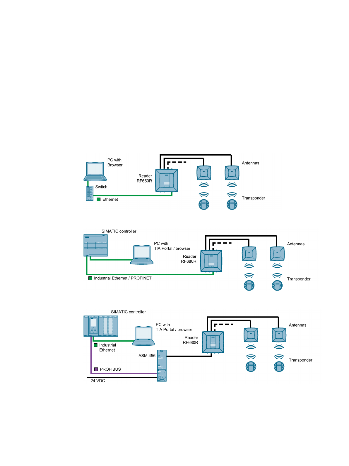
The following figures show examples of some of the of the integration options of the readers.
Note that in all examples, the connection of the readers RF680R and RF685R can be via a
SIMATIC controller both via Industrial Ethernet / PROFINET and via PROFIBUS.
Figure 3-1 RF650R reader in an IT environment
Figure 3-2 RF680R reader in an automation environment (PROFINET)
Figure 3-3 RF680R reader in an automation environment (PROFIBUS)
SIMATIC RF650R/RF680R/RF685R
Configuration Manual, 10/2015, C79000-G8976-C386-03
13
Page 14

Description
3.2
User-specific procedures
3.2 User-specific procedures
Figure 3-4 RF685R in an IT environment, without external antenna
All 3 readers can be integrated in an IT environment (XML). The RF68xR readers can be
integrated both in an IT and in an automation environment (S7).
The RF685R reader can also be operated without external antennas.
The SIMATIC RF650R, RF680R or RF685R UHF readers are preconfigured when shipped
and can be put into operation without any further configuration. When shipped from the
factory, the readers are preconfigured as follows:
● First antenna connector set
● Transmit power: 20 dBm
● IP address:
– RF650R: 192.168.0.254
– RF680R/RF685R: DHCP
As described in the previous section, the SIMATIC UHF readers RF650R, RF680R and
RF685R are designed for different environments and requirements.
If you operate the RF680R and RF685R readers in an automation environment, they are
configured and programmed from the perspective of an S7 user. Integration in third-party
controllers is, of course, also possible. If you operate the RF650R, RF680R and RF685R
readers in an XML environment, they are configured and programmed from the perspective
of an XML user.
If you want to adapt the readers to your requirements, we recommend the following userspecific procedure:
SIMATIC RF650R/RF680R/RF685R
14 Configuration Manual, 10/2015, C79000-G8976-C386-03
Page 15

Description
Procedure as S7 user
Procedure as XML user
3.2 User-specific procedures
1. Connect the hardware
You will find information on this in the section "Connect the hardware (Page 19)".
2. Assign the IP address / device name
You will find information on this in the section "Assigning the IP address / device name
with the PST (Page 23)" or "Assigning the IP address / device name with STEP 7
(Page 25)".
3. Configure reader and if applicable communications module
You will find information on this in the section "Configuration via STEP 7 (PROFINET
device) (Page 29)" and "Configuring with the WBM (Page 33)".
4. Configure / program reader commands
You will find information on this in the section "Interface to the SIMATIC controller
(Page 93)".
1. Connect the hardware
You will find information on this in the section "Connect the hardware (Page 19)".
2. Assign the IP address / device name
You will find information on this in the section "Assigning the IP address / device name
with the PST (Page 23)".
3. Configure the reader
You will find information on this in the section "Configuring with the WBM (Page 33)".
4. Program reader commands
You will find information on this in the section "XML interface (Page 139)".
Later in the document, these symbols will help your orientation and will show you whether
the section is of interest to you or not. Only the sections with user-specific content, in other
words content that is tool/interface-specific contain these symbols. Sections without these
symbols are general and relevant for both areas of application.
SIMATIC RF650R/RF680R/RF685R
Configuration Manual, 10/2015, C79000-G8976-C386-03
15
Page 16

Description
3.2 User-specific procedures
SIMATIC RF650R/RF680R/RF685R
16 Configuration Manual, 10/2015, C79000-G8976-C386-03
Page 17

4
Note
Commissioning the readers in PROFIBUS operation
You will find information on commissioning the RF680R and RF685R readers via a
communications module (PROFIBUS operation) in the manual of the relevant
communications module.
4.1
Important notes on using the device
Safety notices on the use of the device
General notes
WARNING
Safety extra low voltage
There is an additional requirement if devices are operated with a redundant power supply:
WARNING
Opening the device
The following safety notices must be adhered to when setting up and operating the device
and during all work relating to it such as installation, connecting up, replacing devices or
opening the device.
The equipment is designed for operation with Safety Extra-Low Voltage (SELV) by a
Limited Power Source (LPS). (This does not apply to 100 V ... 240 V devices.)
This means that only SELV / LPS complying with IEC 60950-1 / EN 60950-1 / VDE 0805-1
must be connected to the power supply terminals. The power supply unit for the equipment
power supply must comply with NEC Class 2, as described by the National Electrical Code
(r) (ANSI / NFPA 70).
If the equipment is connected to a redundant power supply (two separate power supplies),
both must meet these requirements.
SIMATIC RF650R/RF680R/RF685R
Configuration Manual, 10/2015, C79000-G8976-C386-03
D not open the device when energized.
17
Page 18
Commissioning
NOTICE
Alterations not permitted
Overvoltage protection
NOTICE
Protection of the external 24 VDC voltage supply
Repairs
WARNING
Repairs only by authorized qualified personnel
4.1 Important notes on using the device
Alterations to the devices are not permitted. If this is not adhered to, the radio approvals,
the relevant country approvals (e.g. CE or FCC) and the manufacturer's guarantee are
invalidated.
If the module is supplied via extensive 24 V supply lines or networks, interference by strong
electromagnetic pulses on the supply lines is possible, e.g. from lightning or the switching
of large loads.
The connector for the 24 VDC external power supply is not protected against strong
electromagnetic pulses. Make sure that any cables liable to lightning strikes are fitted with
suitable overvoltage protection.
Repairs may only be carried out by authorized qualified personnel. Unauthorized opening of
and improper repairs to the device may result in substantial damage to equipment or risk of
personal injury to the user.
SIMATIC RF650R/RF680R/RF685R
18 Configuration Manual, 10/2015, C79000-G8976-C386-03
Page 19

Commissioning
4.2
Connect the hardware
Prior to installation and commissioning
NOTICE
Read the manual of the SIMATIC controller you using
NOTICE
Installation/removal with the power off
Procedure
4.2 Connect the hardware
Prior to installation, connecting up and commissioning, read the relevant sections in the
manual of the SIMATIC controller you are using. When installing and connecting up, keep
to the procedures described in the manual.
Wire up the PC or SIMATIC controller and modules to be connected only when the power is
off. Make sure that the power supply is turned off when installing/uninstalling the devices.
Follow the steps below to connect a reader via Ethernet/PROFINET:
1. Install the reader.
2. Connect the reader to the PC or the SIMATIC controller using an Ethernet cable.
– For the Ethernet connection to the RF650R reader, use a connecting cable with an
RJ-45 plug.
– For the PROFINET connection of the RF680R/RF685R reader, use a connecting
cable with an M12 plug (4-pin).
3. If necessary, connect the reader to one or more external antennas.
4. Connect the reader to the power supply using the connecting cable.
The reader is ready for operation when the "R/S" LED is lit/flashes green. If the "R/S" LED is
flashing, the reader is waiting for a connection. If the "R/S" LED is lit constantly, the reader is
connected to the controller or PC.
SIMATIC RF650R/RF680R/RF685R
Configuration Manual, 10/2015, C79000-G8976-C386-03
19
Page 20
Commissioning
Picture
Description
④
4.2 Connect the hardware
Pre-assembled cables therefore permit the ideal and simple connection of the reader. You
will find more information on the cables and wide-range power supply unit in the catalog "ID
10
https://w3app.siemens.com/mcms/infocenter/content/en/Seiten/order_form.aspx?nodeKey=
(
key_9180440&infotype=1)".
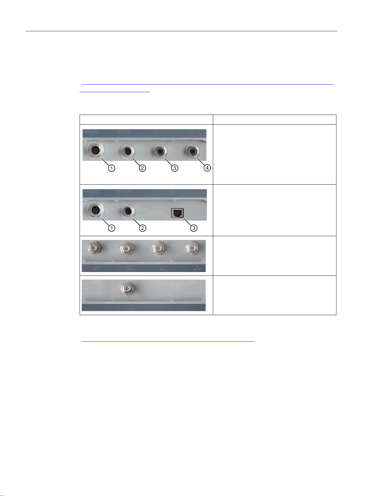
Table 4- 1 Interfaces and antenna connectors of the readers
Interfaces of the RF680R/RF685R readers
① Digital I/O interface (M12, 12-pin)
② Power supply 24 VDC and RS-422 (M12, 8-
pin)
③ Ethernet interface, TCP/IP (M12, 4-pin)
Ethernet interface, TCP/IP (M12, 4-pin)
Interfaces of the RF650R reader
① Digital I/O interface (M12, 12-pin)
② Power supply 24 VDC and RS-422 (M12, 8-
pin)
③ Ethernet interface, TCP/IP (RJ-45 , 8-pin)
Antenna connectors of the RF650R/RF680R
readers
4 x antenna connectors for external antennas
(RP-TNC)
Antenna connector of the RF685R reader
1 x antenna connector for external antenna
(RP-TNC)
For detailed information on mounting the readers as well as ordering data of the readers and
cables, refer to the section "SIMATIC RF600 System Manual
(https://support.industry.siemens.com/cs/ww/en/view/22437600
)".
SIMATIC RF650R/RF680R/RF685R
20 Configuration Manual, 10/2015, C79000-G8976-C386-03
Page 21
Commissioning
4.3
Setup/network topology
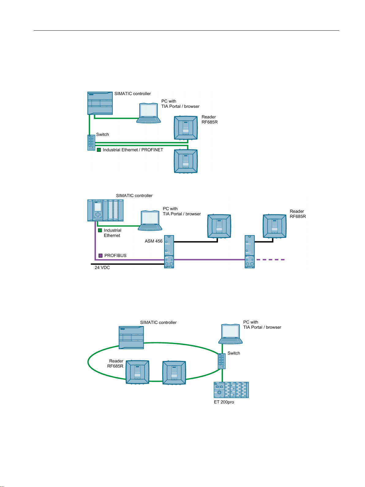
4.3 Setup/network topology
PROFINET communication of the RF680R and RF685R readers can be set up as a star, bus
or ring topology.
Figure 4-1 Sample configuration star topology
Figure 4-2 Sample configuration bus topology
With a bus topology, remember that if the communications connection of a reader to the
controller is interrupted, the communications connection to all downstream readers is also
interrupted.
Figure 4-3 Sample configuration MRP ring topology
SIMATIC RF650R/RF680R/RF685R
Configuration Manual, 10/2015, C79000-G8976-C386-03
21
Page 22

Commissioning
Media redundancy
Setup of an MRP ring topology
4.4
Assign the IP address / device name
4.4 Assign the IP address / device name
Media redundancy is a function that ensures network and system availability. Redundant
transmission links in the MRP topology ensure that an alternative communications path is
made available if a transmission link fails. To make this possible you need to configure the
RF680R and RF685R readers as a client of the Media Redundancy Protocol (MRP) in STEP
7 (Basic / Professional).
MRP is part of PROFINET standardization according to IEC 61158.
To set up an MRP ring topology with media redundancy, you must join both free ends of a
line network topology in the same device. The closing of the line topology to form a ring is via
two network ports of one of the devices (ring ports). With the RF680R and RF685R readers,
the network ports "X1P1" and "X1P2" can function as ring ports.
You will find additional information on setting up an MRP ring topology in the STEP 7 online
help and in the "SIMATIC PROFINET system description
(https://support.industry.siemens.com/cs/ww/en/view/19292127
)".
To achieve ideal communication between the PC and readers or a SIMATIC controller and
readers, you need to assign a unique IP address or device name to each individual reader.
Depending on the environment in which you operate the readers, there are different
procedures as explained below:
● Operating RF650R/RF680R/RF685R readers as an XML user in an IT environment
The unique assignment is based on the IP address or device name using the Primary
Setup Tool V4.2 or higher (PST).
● Operating RF680R/RF685R readers as an S7 user in an automation environment
The unique assignment for PROFINET operation is based on the device name using the
TIA Portal (STEP 7 Basic / Professional V13 or higher).
In PROFIBUS operation via a communications module an IP address needs to be
assigned only for configuration and diagnostics purposes.
The RF650R reader ships with the IP address "192.168.0.254" set in the factory. In the
factory settings, the RF680R and RF685R readers are set to DHCP.
These alternative methods are described below.
SIMATIC RF650R/RF680R/RF685R
22 Configuration Manual, 10/2015, C79000-G8976-C386-03
Page 23
Commissioning
4.4.1
Assigning the IP address / device name with the PST
Requirement
Procedure
4.4 Assign the IP address / device name
This section is intended for both S7 and XML users (RF650R/RF680R/RF685R).
The Primary Setup Tool (V4.2 or higher) is installed and the RF650R/RF680R/RF685R
reader is connected and has started up. You will find the Primary Setup Tool on the DVD
accompanying the reader or on the Internet at "Industry Online Support
(https://support.industry.siemens.com/cs/ww/en/ps
)".
Follow the steps below to assign a new, unique IP address and a unique device name to the
reader:
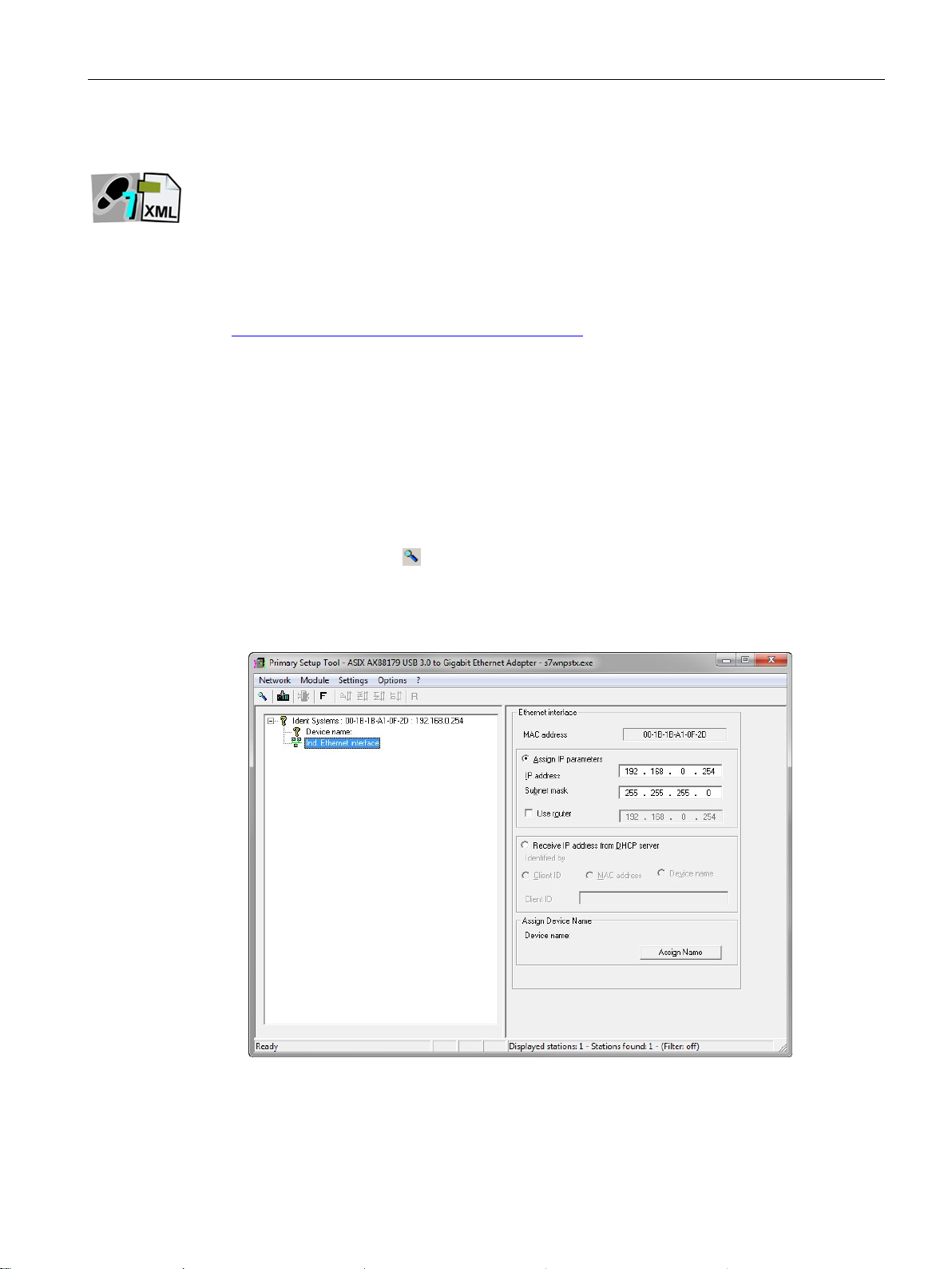
1. Call up the Primary Setup Tool with "Start > All Programs > Siemens Automation >
SIMATIC > Primary Setup Tool".
2. In the menu bar under "Settings > Set PG/PC interface..." select the network adapter via
which the reader is connected to the PC and confirm with "OK".
3. Click on the "Search"
A dialog box opens with the information that a device was found in the network.
4. Click on the "+" character beside the folder symbol in the structure tree and click the entry
"Ind. Ethernet interface".
icon in the toolbar.
Figure 4-4 Assigning an IP address
5. To assign the reader a new IP address, select the "Assign IP parameters" radio button.
6. Enter a new, unique IP address for the reader in the "IP address" input box.
SIMATIC RF650R/RF680R/RF685R
Configuration Manual, 10/2015, C79000-G8976-C386-03
23
Page 24

Commissioning
Note
Waiting time
Wait until the IP address / the device name has been updated. To display the change,
you need to activate the s
Station buzz test
4.4 Assign the IP address / device name
7. Enter the subnet mask of your network in the "Subnet mask" input box.
8. Click on "Assign Name" to assign a unique device name to the reader.
9. Click the "Load"
symbol to transfer the settings to the reader.
10.Confirm the next dialog box with "Yes".
earch function using the "Search" icon .
Result: The reader is assigned the new IP address and a new device name.
If several readers are connected to the network/PC, it is possible to make the LEDs of the
device selected in the output window flash. Using the node flash test, you can identify the
required reader quickly and simply.
Follow the steps below to identify the relevant reader using the flash function:
1. In the menu bar, select the menu command "Network> Browse".
2. Select the required module from the device list.
3. In the menu bar, select the menu command "Module> Flashing".
4. Click the "Start" button.
The LEDs on the selected reader flash.
5. Click the "Stop" button to stop the flashing.
SIMATIC RF650R/RF680R/RF685R
24 Configuration Manual, 10/2015, C79000-G8976-C386-03
Page 25

Commissioning
4.4.2
Assigning the IP address / device name with STEP 7
Note
Restriction when assigning IP addresses
Remember that only the RF680R and RF685R readers can b
device using STEP
only be assigned a unique IP address using the Primary Setup Tool.
Requirement
Procedure
4.4 Assign the IP address / device name
This section is intended only for S7 users (RF680R/RF685R).
e configured as a PROFINET
7. The RF650R reader does not support PROFINET and can therefore
STEP 7 is installed, the RF680R/RF685R readers are linked into the TIA Portal and the
RF680R/RF685R reader is connected and has started up.
You will find further information on linking the readers into the TIA Portal in the section
"Linking readers into STEP 7 (Basic / Professional) (Page 29)".
Follow the steps below to assign a unique device name to the reader:
1. Call up the TIA Portal with "Start > All Programs > Siemens Automation > TIA Portal Vxx".
2. Create a new project.
3. Change to the Project view.
4. Using the project tree, insert a SIMATIC controller in the project using the "Add new
device" menu command.
The device view opens and the SIMATIC controller is displayed.
5. Drag the required reader from the hardware catalog to the project.
6. Change to the network view and connect the reader to the SIMATIC controller.
7. Right-click on the reader.
SIMATIC RF650R/RF680R/RF685R
Configuration Manual, 10/2015, C79000-G8976-C386-03
25
Page 26
Commissioning
4.4 Assign the IP address / device name
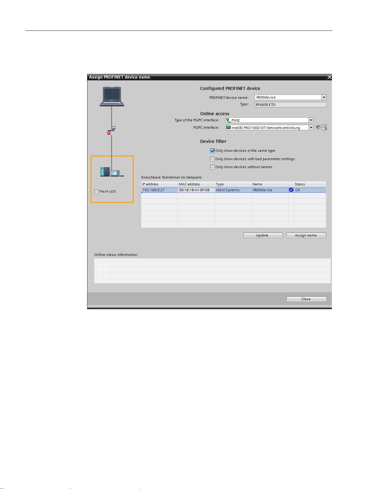
8. In the shortcut menu, select the menu command "Assign device name".
Reaction: The "Assign PROFINET device name" window opens.
Figure 4-5 Assigning a device name
9. Select the connection type in the "Online access" in the "Type of the PG/PC interface"
drop-down list.
10.In the "PG/PC interface" drop-down list in the "Online access" area, select the network
adapter via which the reader is connected to the PC.
11.Click the "Refresh" button to display all reachable nodes in the network.
12.Select the required node from the list.
13.Now click the "Assign name" button to assign the PROFINET device name to the reader.
Result: The reader is assigned the configured PROFINET device name from the project.
SIMATIC RF650R/RF680R/RF685R
26 Configuration Manual, 10/2015, C79000-G8976-C386-03
Page 27

Commissioning
Note
Assigning a device name when replacing a module
When you repl
more information on this in the section "
Station buzz test
4.4 Assign the IP address / device name
ace a module, you can assign the device names automatically. You will find
Replacing a module (Page 243)".
If several readers are connected to the controller, it is possible to make the LEDs of the
device selected in the output window flash. In this case, compare the MAC address of the
device with the displayed MAC address and then select the required reader. Using the node
flash test, you can identify the required reader quickly and simply.
Follow the steps below to identify the relevant reader using the flash function:
1. In the Project tree, select the menu command "Online access > <your online access> >
Update accessible devices".
The available devices are displayed.
2. Select the required RF680R and click the entry "Online & Diagnostics" in the folder of the
selected device.
3. Select the option "Functions > Assign name".
4. Click the "Flash LED" button.
The two LEDs on the selected reader flash.
5. Click the "Flash LED" button again to stop the flashing.
SIMATIC RF650R/RF680R/RF685R
Configuration Manual, 10/2015, C79000-G8976-C386-03
27
Page 28

Commissioning
4.4 Assign the IP address / device name
SIMATIC RF650R/RF680R/RF685R
28 Configuration Manual, 10/2015, C79000-G8976-C386-03
Page 29

5
Note
Configuration of the readers using STEP 7 for PROFIBUS operation
You will find information on configuring the communications module you are using for
PROFIBUS operation in the manual of the relevant communications module.
5.1
Linking readers into STEP 7 (Basic / Professional)
Procedure
This section is intended only for S7 users (RF680R/RF685R).
Note that the RF680R/RF685R readers are only included in the TIA Portal as of STEP 7
Basic/Professional version V14. With older versions as of V13, the readers must be linked
into TIA using an HSP or GSDML file. Using the GSDML file, you can also link the reader
into STEP 7 Classic or third-party systems.
Note that some of the functions of the GSDML file are restricted compared with the HSP file.
Follow the steps below to link the HSP file of the RF680R/RF685R readers into STEP 7:
1. Copy the installation file (*-zip) locally to your PC.
You will find the file on the Internet on the pages of the Industry online support
(https://support.industry.siemens.com/cs/ww/en/view/72341852
2. Extract the *.zip file and copy the *.ispxx files it contains to a directory that you can
access with STEP 7 Basic / Professional.
3. Open the TIA Portal and change to the project view.
4. With the "Options > Support packages" menu command, open the "Detailed information"
dialog.
After opening the this dialog, the "Installation of support packages" tab opens as default
and in the right-hand window, you can see the support packages installed up to now.
5. Click the "Add from file system" button and go to the folder where you stored the *.ispxx
files.
6. Select the required *.ispxx file.
The HSP file for the installation now appears in the "Detailed information" dialog. The
"Installed" column still has the entry "No" for this HSP.
).
7. Select the HSP file and click the "Install" button.
SIMATIC RF650R/RF680R/RF685R
Configuration Manual, 10/2015, C79000-G8976-C386-03
29
Page 30

Configuration via STEP 7 (PROFINET device)
5.2
The TIA Portal (STEP 7 Basic / Professional)
Requirement
Procedure
5.2 The TIA Portal (STEP 7 Basic / Professional)
8. In the next dialog, click the "Continue" button to start the installation.
At the end of the installation, a message appears indicating that the installation was
successful.
9. Click the "Finish" button and restart the TIA Portal.
Result: Your hardware catalog has now been updated in the TIA Portal. If you open the
"Detailed information" dialog again, the "Installed" column for the HSP file now has the entry
"Yes". You will find the RF680R/RF685R readers on the following path in the hardware
catalog: "Detecting & Monitoring > Ident systems > PROFINET > SIMATIC RF600".
As an alternative, you can also link the GSDML file into the TIA Portal. You then install using
the "Options > Install general station description file (GSD)" menu command. When installing
using the GSDML file, you will find the RF680R/RF685R readers on the following path in the
hardware catalog: "Additional field devices > PROFINET IO > Ident systems > Siemens AG
> SIMATIC RF600".
You will find further information and help on linking in files in the online help of the TIA Portal.
The RF680R/RF685R readers can be linked into SIMATIC automation systems using STEP
7 Basic / Professional as of V13 (TIA Portal). The connection is via PROFINET. Following
this, you can configure the reader using the WBM while you control the work with the reader
using the Ident library of the TIA Portal.
The reader is connected, has started up and a device name has been assigned to the
reader. The TIA Portal has been started.
Follow the steps below to create a new project:
1. Call up the TIA Portal with "Start > All Programs > Siemens Automation > TIA Portal Vxx".
2. Create a new project.
3. Change to the Project view.
4. Using the project tree, insert a SIMATIC controller in the project using the "Add new
device" menu command.
The device view opens and the SIMATIC controller is displayed.
5. Drag the required reader type from the hardware catalog to the project ("Detecting &
Monitoring > Ident systems > PROFINET > SIMATIC RF600").
6. Change to the network view and connect the reader to the SIMATIC controller.
SIMATIC RF650R/RF680R/RF685R
30 Configuration Manual, 10/2015, C79000-G8976-C386-03
Page 31

Configuration via STEP 7 (PROFINET device)
Note
Downloading the project
If you have already created an RF680R/RF685R project, you can select this in the start view
of the T
5.3
Overview of the configurable properties
Parameter
Functionality
General
General settings of the reader
PROFINET interface [X1]
All settings of the PROFINET interface
General
Name of the PN interface
Ethernet addresses
Setting of the IP address and device name
an MRP domain etc.
400).
Note: The WBM can only be started if either the PROFINET connection between
5.3 Overview of the configurable properties
IA Portal and open it with the "Load project" button.
To display the reader properties, select the reader in the device view and open the
"Properties" tab.
Figure 5-1 Properties of the reader
The following table provides an overview of all configurable reader parameters:
Table 5- 1 Configurable parameters of the reader
Advanced options Advanced PROFINET options such as update time, port settings, belonging to
Hardware identifier / diagnostics
addresses
Web Based Management Starting the WBM of the reader
Hardware identifier of the PROFINET interface (with a connected S7-1200/-
1500).
Diagnostics address of the PROFINET interface (with a connected S7-300/-
the CPU and reader is established or the reader was assigned the IP address
stored in the project. This means that the device name has been assigned and
the TIA configuration must be loaded on the SIMATIC controller.
SIMATIC RF650R/RF680R/RF685R
Configuration Manual, 10/2015, C79000-G8976-C386-03
31
Page 32

Configuration via STEP 7 (PROFINET device)
Parameter
Functionality
Diagnostics address of the reader (with a connected S7-300/-400).
General
General settings
"IID_HW_CONNECT" variable.
in the "IID_HW_CONNECT" variable.
Digital inputs/outputs
Address parameters of the digital inputs/outputs of the reader.
General
General settings
in the WBM of the reader can be accessed.
Hardware identifier
Hardware identifier parameter of the digital inputs/outputs.
5.3 Overview of the configurable properties
Module parameters Enabling/disabling read-point related diagnostics messages
Possible error messages:
• 0x154D - Internal firmware error
• 0x1591 - Antenna 1 not connected
• 0x1592 - Antenna 2 not connected
• 0x1593 - Antenna 3 not connected
• 0x1594 - Antenna 4 not connected
Configuration management
Hardware identifier / diagnostics addresses
RFID communication Address parameters of the reader
I/O addresses I/O address parameter ("LADDR") of the reader. This parameter is used in the
• Loading configuration data on the reader from the STEP 7 project.
• Saving configuration data of the reader in the STEP 7 project.
Hardware identifier of the reader (with a connected S7-1200/-1500).
Hardware identifier Hardware identifier parameter ("HW-ID") of the reader. This parameter is used
I/O addresses I/O address parameter of the digital inputs/outputs.
Using the set address range (I/O address), the digital inputs/outputs configured
SIMATIC RF650R/RF680R/RF685R
32 Configuration Manual, 10/2015, C79000-G8976-C386-03
Page 33

6
6.1
Starting WBM
Requirement
Procedure
This section is intended for both S7 and XML users (RF650R/RF680R/RF685R).
The RF650R, RF680R and RF685R readers are equipped with a Web server that provides a
Web Based Management (WBM) for configuring the reader. The connection is via Ethernet.
Settings such as transmit power, number and type of the antennas etc. can be made with the
WBM. This can be called up using a Web browser such as the Microsoft Internet Explorer,
Mozilla Firefox or Google Chrome.
The reader is connected, turned on and ready for operation ("RS" LED is lit or flashing
green) and the relevant reader has been assigned an IP address.
To achieve a good workflow with the WBM, we recommend that you use a PC that meets the
following minimum requirements:
● CPU: DualCore with 3 GHz
● RAM: 2 GB
You can start the WBM with the following Web browsers: Microsoft Internet Explorer V9 or
higher, Mozilla Firefox V30 or higher and Google Chrome V36 or higher. The user interface
of the WBM is designed for a screen resolution of 1366 x 786 pixels.
Follow the steps below to start the WBM:
1. Start your Web browser.
2. Enter the IP address of the reader in the address field of your browser.
3. Confirm your entry by pressing the <Enter> key.
Result: The WBM of the reader opens.
SIMATIC RF650R/RF680R/RF685R
Configuration Manual, 10/2015, C79000-G8976-C386-03
33
Page 34

Configuring with the WBM
Note
The connection to the reader cannot be established
If no connection can be established to the reader, che
•
•
•
•
•
6.1 Starting WBM
Figure 6-1 The start page of the WBM
ck the following points:
Make sure that all cables are correctly connected.
Make sure that the reader has started up ("RS LED" lit/flashing green).
Check the IP address of the PC/reader and the subnet mask (you will find further
information on this in the section "
Assign the IP address / device name (Page 22)").
Make sure that the connection is not blocked by a firewall.
Check the connection between the PC and reader using a ping request.
SIMATIC RF650R/RF680R/RF685R
34 Configuration Manual, 10/2015, C79000-G8976-C386-03
Page 35

Configuring with the WBM
6.2
The WBM
NOTICE
Security recommendation: Enable user management
6.2 The WBM
Using the WBM, you can configure the SIMATIC RF650R/RF680R/RF685R readers.
After starting the WBM the first time, no user management is enabled. To make sure that
no unauthorized persons can access the reader settings, we recommend that you enable
the user management and create new user profiles after the first login.
For further information on logging in to WBM and creating/deleting user profiles, refer to the
section "The "User management" menu item (Page 87)".
When you have created new user profiles you need to log in with one of these user profiles
when you restart the WBM.
SIMATIC RF650R/RF680R/RF685R
Configuration Manual, 10/2015, C79000-G8976-C386-03
35
Page 36

Configuring with the WBM
Layout of the WBM
The start window of the WBM is divided into 4 areas:
①
Toolbar
②
Status bar
③
Login and menu tree
④
Main window
⑤
Message area
⑥
Information bar
6.2 The WBM
After successful connection establishment to the reader, the start window of the WBM
appears:
Figure 6-2 Start window of the WBM
SIMATIC RF650R/RF680R/RF685R
36 Configuration Manual, 10/2015, C79000-G8976-C386-03
Page 37

Configuring with the WBM
Toolbar and status bar
Icon
Description
With this button, you can transfer the configuration data set in the WBM to the reader.
the WBM.
With this button, you can save the configuration data set in the WBM on the PC.
er, you also need to click the "Transfer configuration to reader" button.
Note
Loading a configuration
Note that you cannot transfer any user profiles and passwor
configuration file. After loading the configuration file on a new reader, you need to enable
user management and create new user profiles and passwords.
6.2 The WBM
On the left above the main window there are four buttons for transferring/loading/storing the
displayed configuration.
Table 6- 1 The toolbar of the WBM
Transfer configuration to reader
Load configuration from reader
With this button, you can load the configuration data currently set on the reader into
Save configuration as
Load configuration from PC
With this button, you can load the configuration data stored on the PC in the WBM.
Remember that this data is only loaded in the WBM. To transfer the data to the read-
ds to other readers using the
On the right above the main window there is the status bar with the following information:
● Display of the reader status
● Date/time display of the reader
● Drop-down list for selecting the user interface language
SIMATIC RF650R/RF680R/RF685R
Configuration Manual, 10/2015, C79000-G8976-C386-03
37
Page 38

Configuring with the WBM
Login and menu tree
Menu items
Functions
Settings
Diagnostics
6.2 The WBM
At the left top edge of the WBM there is a the login and menu tree. Below the login/logout
area, there are various menu items. The currently selected menu item is highlighted in dark
blue.
The following table provides an overview of the menu items and the functions they provide.
Table 6- 2 The menu structure of the WBM
Start page
General
Read points
Tag fields
Filters
Digital outputs
Communication
Adjust antennas
Activation power
• System overview
• Viewing device-specific information
• Entering customer-specific plant designation
• Selecting a country profile and channels
• Enabling/disabling categories of log events
• Defining read points and assigning antennas
• Specifying antenna parameters
• Setting algorithms to improve reading quality
• Assigning tag fields
• Assigning filters
• Setting triggers
• Creating and editing tag fields
• Creating and editing filters
• Setting the behavior of digital outputs
• Making communications settings
• Optimization of the antenna alignment
• Detect activation power
SIMATIC RF650R/RF680R/RF685R
38 Configuration Manual, 10/2015, C79000-G8976-C386-03
Tag monitor
Log
Messages
Edit transponder
User management
• Displaying the read quality
• Overview of the identified transponders
• Overview of the log entries
• Overview of the messages of the WBM
• Changing EPC-IDs
• Reading out transponder data and writing to tag fields
• Locking transponder access
• 'Destroying' transponders
• Enabling/disabling user management
• Creating and deleting user profiles
• Changing passwords
Page 39

Configuring with the WBM
Menu items
Functions
Main window
Note
Entering values in text boxes
Apart from man
•
•
•
The value is set to the minimum or maximum value.
Message area
Information bar
6.2 The WBM
System
Help
• Updating the firmware
• Resetting readers to the factory settings
• Importing certificates
• Documentation relevant for the reader
If you are logged in to the WBM as a "User", some menu items can only be used with certain
restrictions. You will find a list of the restrictions in the section "The "User management"
menu item (Page 87)".
The main window shows the contents of the selected menu items. Here, you can configure
the various menu-dependent parameters.
ual entry of values, you can also change values with the following buttons:
Arrow up / down
The value is increased or decreased by one increment.
PgUp / PgDn
The value is increased or decreased by ten increments.
Home / End
The message area displays all WBM-related error messages and warnings (e.g. transfer
errors). The message is displayed here are entered automatically in the "Settings Messages" menu item.
The information bar displays deviations between the settings in the user interface of the
WBM and the configuration stored on the connected reader. Minor deviations are shown on
an orange background; changes that require the reader to be restarted are shown on a red
background.
SIMATIC RF650R/RF680R/RF685R
Configuration Manual, 10/2015, C79000-G8976-C386-03
39
Page 40

Configuring with the WBM
6.3
The menu items of the WBM
6.3.1
The "Start page" menu item
Device-specific information
6.3 The menu items of the WBM
The "Start page" menu item is divided into 5 areas.
● Device-specific information
● Plant designation
● Address information
● Reader clock
● Configuration display
Figure 6-3 The "Start page" menu item
The first area contains device-specific information. The "Device type", "MLFB" and
"Hardware" boxes are specified in the factory. The content of the "Firmware" and "Firmware
version" boxes depends on the firmware stored on the reader. Using the "Update firmware"
link, you jump to the "System" menu item in which you can update firmware. The
"Configuration ID" box contains a unique identifier for the configuration that was last
activated on the reader or loaded on the reader. Click the "Default configuration" button to
reset the parameters shown in the user interface to the default values. When you restore the
default configuration, address information (IP address, device name) is retained.
SIMATIC RF650R/RF680R/RF685R
40 Configuration Manual, 10/2015, C79000-G8976-C386-03
Page 41

Configuring with the WBM
Plant designation
Address information
Reader clock
Note
The reader time always corresponds to UTC time
Note that the time of day of the reader clock corresponds to UTC time and cannot be
adapted to time zones. By clicking the
system is transferred to the reader. This time of day is retained on the reader for at least two
days even without a power supply.
Configuration display
6.3 The menu items of the WBM
The second area contains input boxes with which you can store your own device-specific
information on the reader. Among other things, this is intended to make it easier to identify
the individual readers.
The third area contains all the important address information with which the PC or controller
can identify the reader. You can assign the IP address and PN device name to the reader
using the "PST" or "STEP 7" tools. With the "Identify" button, you can trigger and stop a
flashing signal on the connected reader. This allows fast and simple visual identification of
the connected reader.
With the "Synchronize with PC" button, you can synchronize the reader clock with the time in
your operating system.
button, the local time of day stored in your operating
The current configuration is shown to the right of the four areas. The schematic
representation contains information on the connected reader type and antennas as well as
the antenna cables being used including the cable loss.
SIMATIC RF650R/RF680R/RF685R
Configuration Manual, 10/2015, C79000-G8976-C386-03
41
Page 42

Configuring with the WBM
6.3.2
The "Settings - General" menu item
Country profile
Channels
6.3 The menu items of the WBM
The "Settings - General" menu item is divided into 5 areas:
● Country profile
● Channels
● Log settings
● Misc
● Extended settings
Figure 6-4 The "Settings - General" menu item
From the "Country profile" drop-down list, you can select the radio profile the reader will use.
The "Channels" area is adapted depending on the radio profile selected. The radio profiles
depend on the country or region. To ensure that the reader keeps to the local radio
regulations, select the country profile belonging to your country. It is not possible to transfer
an incorrect radio profile to the reader.
The "Channels" area displays the channels with the frequencies of the selected country
profile. Disable the check boxes of the channels that the reader should not use.
SIMATIC RF650R/RF680R/RF685R
42 Configuration Manual, 10/2015, C79000-G8976-C386-03
Page 43

Configuring with the WBM
Log settings
Parameter
Description
General
ERRORS
Error and alarm messages of the reader
FILTER
Transponders that were filtered out.
COMMANDS
Commands of the user application
EVENTS
Recording of all tag events
Additional information
read transponder data.
Call parameters
Call parameters for the commands of the user application
values
zation, channel, ...).
Service
CMD_XML
Frames on the XML interface
CMD_PLC
Internal frames on the PLC interface
CMD_WEB
Internal frames between Web server and reader
UHF_LOGIC
Internal frames to the UHF part of the reader
Misc
Parameter
Description
input, the reader can optimize the transponder identification.
Value range
1 ... 1000
6.3 The menu items of the WBM
In the "Log settings" area, you can use the check boxes to decide which events are entered
in the log. The log is structured as a circular buffer. Remember that a higher degree of detail
for the data can have a negative effect on the computing power of the device.
Table 6- 3 Description of the parameters of the log
COMMON Messages relating to general events:
e.g. reader startup, login to the WBM, ...
GPIO Changes to the digital inputs/outputs
Return value Return values for the commands of the user application and for the written or
Extended acquired
Additional data obtained when the transponder was identified (antenna, polari-
The "Misc" area contains various general reader parameters.
Table 6- 4 Description of the parameters
Expected number of
transponders
The number of transponders expected to be read with the reader. With this
Increment 1
SIMATIC RF650R/RF680R/RF685R
Configuration Manual, 10/2015, C79000-G8976-C386-03
43
Page 44

Configuring with the WBM
Parameter
Description
large transponder populations to be identified quickly and reliably.
accessing transponders that have already been accessed.
Value range
0 ... 25.5 s
Increment
0.1 s
(intermission). 1)
Value range
1 ... 65535
Increment
1
Value range
0 ... 65535 ms
Increment
1 ms
ed when the antenna is accessed.
1)
You will find more detailed information on the intermission parameters below.
6.3 The menu items of the WBM
Status A/B flip Activation/deactivation of the A/B flip function
This function ensures that with every read operation, two read steps are performed. With the first read step, all transponders in status. "A" (default status)
located in the antenna field are identified. With the second read step all transponders in status "B" located in the antenna field are identified. This increases the probability that all transponders will be identified.
Normally transponders are in status "A". If a transponder is identified, depending on the set session. it changes briefly to status "B" before it automatically
changes back to status "A". This distinction between these statuses allows
Modulation scheme Specifies the data transfer rate, radio, profile and coding:
• Tx: Data transfer rate from reader to transponder
• Rx: Data transfer rate from transponder to reader
• Miller/FM0: Coding of the transponder signal
Miller is used with the "Dense Reader Mode". The "Dense Reader Mode"
allows the operation of neighboring reader systems on an identical frequency channel. If an FM0 profile is selected, neighboring readers can
have greater influence on each other.
• ISO 18000-6B: Changeover of the transponder standard
When using transponders of the ISO 18000-6B standard (U code HSL),
this scheme must be used. Note that mixed operation with transponders of
the ISO 18000-6B and ISO 18000-6C standard is not possible.
Carrier off delay [s] Off delay of the carrier frequency in seconds. This mechanism can reduce the
time required to access transponders that are accessed more than once in
succession. This time specifies how long the reader remains active after transponder access. During the off delay time, the reader is quicker when re-
Inventories without
Number of inventories to be taken without being interrupted by a send pause
intermission
Intermission max
[ms]
Maximum duration of the intermission in milliseconds between the "inventories
without intermission". The length of time of the individual send pauses vary
randomly within the range of values you have specified. 1)
Cyclic
antenna test
Activating/deactivating the cyclic antenna test.
If the cyclic antenna test is active, the reader checks whether or not the anten-
nas are plugged in and connected to the reader. To do this, the antennas are
accessed with minimum power. To make sure that antennas radiate power
only when this is specifically required, you can disable the antenna test.
Without the cyclic antenna test, an interrupted connection can only be detect-
SIMATIC RF650R/RF680R/RF685R
44 Configuration Manual, 10/2015, C79000-G8976-C386-03
Page 45

Configuring with the WBM
Extended settings
Parameter
Description
and the red flashing "ER" LED. If the "Detailed error codes (LED)" check box is
play in the section "How the LED status display works (Page 233)".
only applies to user data > 128 bytes.
Intermissions
Note
Delay due to intermissions
Remember that intermissions delay the other algorithms.
6.3 The menu items of the WBM
Table 6- 5 Description of the parameters of the extended settings
Detailed error codes
(LED)
6 bit coding (acc. So
VDA5500)
Enabling/disabling the detailed error codes.
This area exists only with the RF680R/RF685R readers.
Error messages are indicated by red flashing status LEDs (RF680R/RF685R)
enabled, a separate LED pattern is assigned to every error in the LED status
display. Disable the "Detailed error codes (LED)" check box to disable the
alternative LED error display. You will find more information on the LED dis-
Enabling / disabling the 6 bit coding
When 6 bit coding is enabled, the reader identifies transponders written ac-
cording to VDA5500 The access to the user data stored in the 6 bits is converted transparently to 8 bits.
When the USER memory area "MB11" is accessed, the most significant bit of
the "Data Byte-Count Indicator" is not evaluated by the reader. This restriction
Random intermissions can be used to reduce the mutual influence between RFID devices in
environments with a high reader density.
The incidence and duration of the intermissions can be set depending on the required
availability of the RFID data. The following figure shows the effects of the intermissions:
Figure 6-5 Example of intermissions
SIMATIC RF650R/RF680R/RF685R
Configuration Manual, 10/2015, C79000-G8976-C386-03
45
Page 46

Configuring with the WBM
6.3.3
The "Settings - Read points" menu item
Note
Parallel operation of read points
Note that simultaneous read/write/inventory access to multiple
The length of the delay depends on the time required for the command and the number of
commands.
6.3 The menu items of the WBM
In the "Settings - Read points" menu, up to four logical read points can be defined depending
on the reader type. A logical read point is, for example, an incoming goods gate in logistics
or a machine infeed on a production line. A read point, on the other hand, can be assigned
one or more antennas required to cover the identification area of the read point.
The settings are structured identically for each read point and divided into the following 6
areas:
● Read point name
● Assigned antennas
● Algorithms
● Tag fields
● Filters
● Trigger
read points leads to delays.
The icon in the Read point tab shows how many antennas are assigned to the particular
read point.
SIMATIC RF650R/RF680R/RF685R
46 Configuration Manual, 10/2015, C79000-G8976-C386-03
Page 47

Configuring with the WBM
Read point name
Assigned antennas
6.3 The menu items of the WBM
Figure 6-6 The "Settings - Read points" menu item
In the input box, you can assign a name to the read point (e.g. "incoming goods gate 5" or
"welding robot 21").
In the "Assigned antennas" area, you can assign each read point 1 to 4 antennas depending
on the connected reader type. To do this, select the check boxes of the relevant antennas in
the list. If an antenna has already been assigned to a read point, a green icon is displayed
on the right. If the check box is enabled, the antenna is assigned to the selected read point.
To specify antenna parameters for the individual antennas, select the required antenna in
the list.
SIMATIC RF650R/RF680R/RF685R
Configuration Manual, 10/2015, C79000-G8976-C386-03
47
Page 48

Configuring with the WBM
Parameter
Description
For example, the location of the antenna
parameters.
Value range
5 ... 33/36 dBm
3 ... 2000/4000 mW
Increment
0.25 dBm
--
verted in the air and depends on the antenna being used. Here, you can either
an antenna being used directly.
Value range
-15 ... 15 dBi
Increment
0.25 dBi
The cable loss depends on the cable being used. Here, you can either select a
used directly.
Value range
0 ... 63.75 dB
Increment
0.25 dB
all antennas
this antenna to all other antennas.
Note: The unit (ERP/EIRP) depends on the selected radio profile.
The RSSI threshold specifies the signal strength above which a transponder is
should not be read, it is possible to derive an RSSI threshold value.
Value range
0 ... 255
Increment
1
6.3 The menu items of the WBM
Table 6- 6 Description of the antenna parameters
Description Input box for storing device-specific information.
Radiated power Basic radiated power that the antenna outputs.
Note: The unit (ERP/EIRP) depends on the selected radio profile.
The two input boxes are linked together. If the value in one of the input boxes
is changed, the value of the other input box will be adapted automatically. The
actual radiated power emitted may be lower due to other components and/or
Gain The antenna gain affects the actual radiated power.
The gain of an antenna describes how much of the power fed in can be con-
select an antenna based on its name or enter the value of the antenna gain of
Cable loss The cable loss affects the actual radiated power.
cable based on its name or enter the value of the cable loss of a cable being
Apply parameters to
Effective
radiated power
RSSI threshold
Button that transfers the entered values (radiated power, gain, cable loss) of
The actual radiated power is made up of the transmit power emitted by the
reader, the cable loss and the antenna gain. It is possible that the target value
for the radiated power is never reached in reality due to the use of long cables
and antennas with low gain.
identified. Only the transponders that reach the RSSI threshold are entered in
the list of identified transponders.
In reflecting environments (metal reflects UHF waves), transponders could be
detected that are not located directly in the antenna field and therefore should
not actually be "read". The RSSI value of these transponders is usually noticeably lower than the RSSI value of transponders located directly in antenna
field. Such transponders can be filtered out with a suitable RSSI threshold
value.
In the "Diagnostics - Tag monitor" menu item, all the detected transponders
are displayed along with their RSSI values. From the RSSI values of the transponders that should be read and the RSSI values of the transponders that
SIMATIC RF650R/RF680R/RF685R
48 Configuration Manual, 10/2015, C79000-G8976-C386-03
Page 49

Configuring with the WBM
Parameter
Description
sponder signals are no longer identified by the reader. This attenuation applies
readers and transponder populations.
Value range
0 ... 31.75 dB
Increment
0.25 dB
ries).
Algorithms
6.3 The menu items of the WBM
Input attenuation The input attenuation weakens the strength of received transponder signals at
the reader input. Increasing the attenuation means that received weak tran-
both to transponder responses as well as to signals of neighboring readers.
Adapting this parameter helps to reduce disruptions caused by neighboring
Polarization The polarization indicates the alignment of the waves of the antenna and de-
pends on the antenna being used. Most antennas have an unchangeable
polarization.
The polarization of the internal antenna of the RF685R reader can be set. If
you use the internal antenna of the RF685R reader, you also need to enable
the required polarization using the corresponding check box. If more than one
check box is selected, the polarization is changed with each inventory. This
increases the probability of identification in difficult radio conditions but does,
however, increase the access time (time required for the additional invento-
Compared with other frequency bands (LF, HF), UHF RFID has the following special
properties:
● Large distances in the range of several meters,
● Reflection of the waves on metal surfaces,
● Region-dependent bandwidth restricted by regulations
In conjunction with the fact that electromagnetic waves in the UHF range are not visible, this
often leads to unwanted or incomprehensible responses in UHF systems. Typical, simple
examples include:
● Not everything is read or even nothing is read.
● Reading works but writing does not.
● Transponders are identified that should not be identified at all.
There are often simple explanations for these responses and therefore usually also
solutions. Algorithms are additional functions that help you to achieve the required
functionality even in difficult radio conditions. The following environmental conditions are
possible causes of this response:
● There are several readers in a restricted space, e.g. every 3 to 5 meters along a
production line (high reader density).
● The objects to be identified or the transponders are close together (the distance from
each other is less than the antenna field).
● There is a lot of metal in the environment (e.g. production environment with metallic
conveyor technology, loading doors with metal ramps)
● The objects to be identified are on a metal surface.
SIMATIC RF650R/RF680R/RF685R
Configuration Manual, 10/2015, C79000-G8976-C386-03
49
Page 50

Configuring with the WBM
Note
Algorithms for trained users
Note that the following algorithms were designed specifically for trained users. Settings in
individual algorithms have effects on other algorithms. You s
algorithms when you are aware of the interdependencies between the various algorithms
and their purpose.
6.3 The menu items of the WBM
With the algorithms, you can optimize the write/read settings to ensure reliable
communication between reader and transponder. If none of these conditions applies, the use
of algorithms is usually unnecessary.
hould only work with the
Click the "Adopt parameters from read point" button to transfer all parameters of the
algorithms and the session from another read point to this read point.
SIMATIC RF650R/RF680R/RF685R
50 Configuration Manual, 10/2015, C79000-G8976-C386-03
Page 51

Configuring with the WBM
Algorithm
Description
generated in the process.
are never reported as "not identified" (lost).
the transponder data by the reader has been completed.
glimpsed
Transponder was scanned the first time.
Count".
6.3 The menu items of the WBM
The icons of the algorithms indicate whether the algorithm is activated ( ) or deactivated
).
(
Table 6- 7 Description of the algorithms
Smoothing This algorithm ensures that only transponders that could be identified often
enough will be reported as "reliably identified". Transponders that only appear
briefly in the antenna field (e.g. due to overshoot) are filtered out.
Observed Count The value specifies how often a transponder needs to be
identified before it is reported as "reliably identified" (observed).
When entering the value "1", the transponder changes to
the status "observed" during the first recognition. The
"Glimpsed" event as well as the "Observed" event are
Lost Count The value specifies how often a transponder reported as
"reliably identified" (observed) may no longer identified by
cyclic inventories before it is reported as being "not identified" (lost).
The value "0" indicates that the lost event is generated at
the same time as the observed event.
If you enter the maximum value "65535", transponders
unknown The transponder is unknown to the reader. The tran-
sponder has either never been identified or processing of
observed The transponder was identified reliably for at least "x"
read cycles. The number "x" is specified with "Observed
SIMATIC RF650R/RF680R/RF685R
Configuration Manual, 10/2015, C79000-G8976-C386-03
51
Page 52

Configuring with the WBM
Algorithm
Description
is increased in each step.
can be increased as maximum.
with the specified maximum dB increase.
6.3 The menu items of the WBM
Read/Write Power
Ramp
The effect of this algorithm is to ensure that there is enough power available
when executing a command (Read, Write, Lock, Kill command). If a command
fails to execute, it is repeated with an increased radiated power. The radiated
power is increased step-by-step until the power is adequate to execute the
command or until the specified maximum value is reached.
If a value is entered only for "Boost" and not for "Boost max", only write access
with increased power are performed. If the value = 0 is entered for both parameters, there are no power increases for write/read access.
Note: With the "READ" command, there is no "initial boost". The power currently set by the panel around is used as the output power (current).
Boost [dB] The value specifies by how many dB the radiated power
Boost max [dB] The value specifies by how many dB the radiated power
Command Retry The effect of this algorithm is that commands are executed reliably. If the
command fails to execute, it is repeated.
The algorithm is linked to the "Read/Write Power Ramp" algorithm and is only
started when no command could be executed despite the power ramp. If no
"Read/Write Power Ramp" is set, the commands are repeated with the current
power.
Retries The value specifies how often the command is repeated
SIMATIC RF650R/RF680R/RF685R
52 Configuration Manual, 10/2015, C79000-G8976-C386-03
Page 53

Configuring with the WBM
Algorithm
Description
Boost max = 5 dB, Inventories = 10 ⇒ Step size = 0.5 dB
creased.
can be increased as maximum.
until the maximum radiated power is reached.
6.3 The menu items of the WBM
Inventory Power
Ramp
This algorithm automatically increases the radiated power of the antenna in
steps. If the specified number of expected transponders is not detected in
each inventory, the power is increased step by step up to the specified maximum value. This, for example, compensates for fluctuating radio conditions.
This algorithm is only used when taking inventories (e.g. "presence mode" in
PROFINET operation). With read/write commands, the algorithm is not started.
The step size of the individual increases is calculated as follows: Boost max /
Inventories
Example:
Expected Tags The value specifies the minimum number of transponders
that should be identified per read point in every inventory.
If this value is not reached, the radiated power is in-
Boost Max [dB] The value specifies by how many dB the radiated power
Inventories The value specifies the number of inventories to be taken
SIMATIC RF650R/RF680R/RF685R
Configuration Manual, 10/2015, C79000-G8976-C386-03
53
Page 54

Configuring with the WBM
Algorithm
Description
ct of this algorithm is that from a number "x" of identified transponders,
transponder compared with the highest RSSI value.
next new entry deletes the oldest entry.
Sessions
6.3 The menu items of the WBM
RSSI Delta The effe
only the "strongest" are reported. Transponders will only be reported as "reliably identified" if their RSSI value is at least as high as the RSSI value of the
best identified transponder minus the RSSI Δ value.
This algorithm is used only when taking inventories, for example with the XML
commands "readTagIDs" and "readObservedTagIDs" and in the "presence
mode" with PROFINET.
RSSI Delta The value specifies the maximum RSSI difference of the
Black List The effect of this algorithm is that transponders that have already been pro-
cessed are hidden. This function is particularly useful at read points at which
only one individual transponder or a few transponders should be identified but
the antenna field is larger than the distance between the neighboring transponders.
With suitable XML or S7 commands, these transponders can be included in
the black list and therefore filtered out. For example because these transponders have already been identified or processed.
Size The value specifies the maximum number of transpond-
ers (EPC-IDs) that can be entered in the black list.
The black list is a circulating buffer with a configurable
size. If all the entries in the black list are occupied, the
The way in which sessions work is very complex and it is recommended that only trained
users should use them. How they work is described in the "EPCglobal Specification
(http://www.gs1.org
)".
SIMATIC RF650R/RF680R/RF685R
54 Configuration Manual, 10/2015, C79000-G8976-C386-03
Page 55

Configuring with the WBM
Sequence of the algorithms
Tag fields
6.3 The menu items of the WBM
The following table figure shows an overview of the algorithms over time.
Figure 6-7 Sequence of the algorithms
In the "Tag fields" area, you can assign tag fields to a read point. Tag fields are logical
memory areas of a transponder that have symbolic names. To read out the tag fields from
every transponder automatically, these must be assigned to the read points. This additional
data is sent along with the "TagEventReports" via the XML interface.
SIMATIC RF650R/RF680R/RF685R
Configuration Manual, 10/2015, C79000-G8976-C386-03
55
Page 56

Configuring with the WBM
Icon
Description
quired tag field from the drop-down list.
Click the button to remove tag fields already assigned to the read point.
Tag fields" menu item.
Filters
Icon
Description
required filter from the drop-down list.
ters" menu item.
Click the button to remove filters already assigned to the read point.
ters" menu item.
6.3 The menu items of the WBM
The content of the tag fields is output only via the tag events (Page 214) of the XML
commands.
Table 6- 8 Description of functions
Assign tag field
Click the button to assign existing tag fields to the read point. You can select the re-
Create new tag field
Click the button to create new tag fields. The button acts as a link to the "Settings -
Tag fields" menu item.
Delete tag field
Edit tag field
Click the button to edit existing tag fields. The button acts as a link to the "Settings -
You will find more information on the tag fields in the section "The "Settings - Tag fields"
menu item (Page 58)".
In the "Filters" area, you can assign filters to the read point. The data required for the
comparison with the filter criteria is read out after reliable identification of a transponder.
Depending on the filter evaluation (criterion applies / does not apply), identified transponders
are either filtered out or not.
Table 6- 9 Description of functions
Assign filter
Click the button to assign existing filters fields to the read point. You can select the
Create new filter
Click the button to create new filters. The button acts as a link to the "Settings - Fil-
Remove filters
Edit filters
Click the button to edit existing filters. The button acts as a link to the "Settings - Fil-
You will find more information on filters in the section "The "Settings - Filters" menu item
(Page 60)".
SIMATIC RF650R/RF680R/RF685R
56 Configuration Manual, 10/2015, C79000-G8976-C386-03
Page 57

Configuring with the WBM
Trigger
Condition
Description
as long as the selected input/output is in the specified state "On" or "Off".
CONTINUOUS
With this condition, the reader takes inventories continuously.
Following this, there is a pause with the value set in the "Timer" box.
6.3 The menu items of the WBM
In the "Trigger" area, you can specify the conditions that will trigger inventories. If one of the
assigned conditions applies, inventories are taken. With "Trigger action" you can set whether
the response to the trigger is that
● a specified/permanent number of inventories is taken or
● inventories are taken for a specified/permanent time [ms].
These conditions are also used with the XML command "triggerSource".
If you do not specify a trigger, you can start inventories using the corresponding XML
commands ("triggerSource") or SIMATIC blocks ("Inventory", "Read_xxx"). Note that
configuring triggers is unnecessary for operation using S7.
Click the button
to specify up to two conditions. Click the button to remove already
specified conditions.
Table 6- 10 Description of the trigger conditions
IO_LEVEL With this condition, the reader continues to take inventories uninterrupted
IO-EDGE With this condition, the reader takes inventories once as set in "Trigger
action". When there is an edge change at the selected input.
TIMER With this condition, the reader takes inventories as set in "Trigger action".
SIMATIC RF650R/RF680R/RF685R
Configuration Manual, 10/2015, C79000-G8976-C386-03
57
Page 58

Configuring with the WBM
6.3.4
The "Settings - Tag fields" menu item
Tag fields
6.3 The menu items of the WBM
In the "Settings - Tag fields" menu item, you can create and edit tag fields. Tag fields are
logical memory areas of a transponder that have symbolic names. Memory areas are
defined by a logical name, the memory bank, a memory address and the length. If a tag field
is created and assigned to a read point, the data of every reliably identified transponder is
read out automatically. This data is then signaled with each "observed" "TagEventReport"
via the XML interface to the user application.
This page is divided into 3 areas:
● Tag fields
● Tag field properties
● Transponder memory configuration
Figure 6-8 The "Settings - Tag fields" menu item
The "Tag fields" area contains a list of all tag fields that already exist. To edit a tag field,
select the required field in the list. The selected tag field is highlighted in color. Click the
"Insert" button to create a new tag field. Click the "Delete" button to delete the selected tag
field.
SIMATIC RF650R/RF680R/RF685R
58 Configuration Manual, 10/2015, C79000-G8976-C386-03
Page 59

Configuring with the WBM
Tag field properties
Parameter
Description
Name
Input field for assigning a logical name/ descriptive title to the tag field.
is located.
Address starting at which the data will be read out/written.
Number of bytes to be read out or written starting at the start address.
Value range
1 ... 1024 bytes
Transponder memory configuration
Example
Explanation of the memory structure
6.3 The menu items of the WBM
In the "Tag field properties" area, you can adapt the parameters of the individual tag fields.
Table 6- 11 Description of the parameters of the tag fields
Bank Drop-down list for selecting the memory bank in which the memory area
Start address
Value range 0 ... 65535 bytes
Length
The "Transponder memory configuration" area contains a graphic to illustrate the memory
configuration and the memory areas of a UHF transponder.
The production date of a product is stored on a transponder in the USER memory area
(memory bank 3). The production date is located at address 10 and is 8 bytes long. The
corresponding tag field is created and assigned to a read point. Following this, with each
object/transponder identification (TagEvent "Observed", the production date of the object is
read out automatically and sent to the XML user application with the EPC-ID of the
transponder.
The transponder memory is divided into four different memory banks.
Figure 6-9 Transponder memory configuration
SIMATIC RF650R/RF680R/RF685R
Configuration Manual, 10/2015, C79000-G8976-C386-03
59
Page 60

Configuring with the WBM
Memory type
Description
USER
Freely writable "USER" memory area
memory area.
RESERVED
Contains the access and kill password.
6.3.5
The "Settings - Filters" menu item
6.3 The menu items of the WBM
Table 6- 12 Description of the memory banks
TID Specified by the manufacturer. The TID contains the class identifier and
depending on the transponder type also the serial number of the transponder.
EPC Contains the EPC-ID data, the protocol information (Protocol Control
Word) and the CRC data of the transponder. You can write to the EPC
In the "Settings - Filters" menu item, you can create and edit filters. This page is divided into
3 areas:
● Filters
● Filter properties
● Transponder memory configuration
Figure 6-10 The "Settings - Filters" menu item
SIMATIC RF650R/RF680R/RF685R
60 Configuration Manual, 10/2015, C79000-G8976-C386-03
Page 61

Configuring with the WBM
Filters
Filter properties
Property
Description
Name
Input box for assigning a logical name/ descriptive title to the filter.
is located.
Address starting at which the filter will be checked.
specified here affects the length of the input boxes "Mask" and "Value".
Value range
1 ... 1024 bytes
sentation).
Possible characters
0 ... 9, A ... F
You can choose between the two input modes "Overwrite" and "Insert".
Example: 00FF → Bits 0 ... 8 of the criterion will be checked.
Possible characters
0 ... 9, A ... F
and the mask.
6.3 The menu items of the WBM
The "Filters" area contains a list of all created filters. To edit a filter profile, select the
required filter in the list. The selected filter is highlighted in color. Click the "Insert" button to
create a new filter. Click the "Delete" button to delete an existing selected filter.
In the "Filter properties" area, you can adapt the properties of the individual filters. To allow
filter functions to take effect, the information defined in the filter must be read out from the
transponders and compared with the filter criteria.
Table 6- 13 Description of the filter properties
Bank Drop-down list for selecting the memory bank in which the memory area
Start address
Value range 0 ... 65535 bytes
Length Number of bytes to be checked starting at the start address. The value
Criterion Specifies which value the checked positions must contain HEX repre-
ASCII Hiding/unhiding the ASCII view.
When the ASCII view is active, the values of the criterion are shown
additionally in ASCII notation. You can edit the values both in the HEX
format or in the ASCII format.
Mask Showing/hiding the mask.
Specifies which positions of the criterion should be checked.
Initialize data Show/hide the view for initializing the data.
Using the initialization function, you can preset the boxes of the criterion
SIMATIC RF650R/RF680R/RF685R
Configuration Manual, 10/2015, C79000-G8976-C386-03
61
Page 62

Configuring with the WBM
Property
Description
carded or processed further.
Transponder memory configuration
Explanation of how filters work
Example scenario
6.3 The menu items of the WBM
Inclusive/exclusive filters Radio button to specify the condition when the transponder processing
will continue.
• Inclusive filter:
The transponder is processed further when the filter criteria mask
and value match.
• Exclusive filter:
The transponder is processed when the filter criteria mask and value
do not match.
Unreadable filter data Radio button to specify what happens if the filter data is not legible, for
example because the transponder was not located long enough in the
antenna field. Depending on this setting, such transponders are dis-
The "Transponder memory configuration" area contains a graphic to illustrate the memory
configuration and the memory areas. For a detailed description of the memory structure,
refer to the section "The "Settings - Tag fields" menu item (Page 58)".
By using filters and depending on the filter criteria, you can separate out specific
transponders that will not be processed any further. For example in environments with
different product types, you can use filters to filter out the product types that are unimportant
for the application or only identify the relevant product types. This is only possible if the
information in the memory area of the transponder has been processed accordingly.
A forklift truck takes a pallet with goods from the conveyor belt to store it in the warehouse
and in doing so drives through an RFID gate. Both the pallet and the products on the pallet
are fitted with transponders. During the remainder of the process, only the information about
the palette is necessary. Assign a filter-relevant ID to the transponder of the pallet. Write, for
example, to the 10th position in the EPC-ID of all pallet transponders the value "3". The
EPC-IDs of the goods transponders, on the other hand, must not have "3" at the 10th
position.
With a suitable filter, (value "3" at the 10th position of the EPC-ID), you can now filter out all
goods transponders and only identify and process the pallet transponders.
If a filter is active, the appropriate data is read out from each identified transponder and
checked against the filter criteria. Depending on this check, transponders are discarded or
processed further. A distinction can be made between inclusive and exclusive filtering.
SIMATIC RF650R/RF680R/RF685R
62 Configuration Manual, 10/2015, C79000-G8976-C386-03
Page 63

Configuring with the WBM
Example of a filter - "Pallet"
6.3 The menu items of the WBM
The following filter example shows how to create the suitable filter for the sample scenario
described.
1. Click on the "Insert" button and select the newly created filter.
2. Name: Enter a name in the input box.
3. Bank: Select the memory area "1 - GEN2 - EPC" from the drop-down list.
4. Start address: Enter "8" in the input box as the start address.
The EPC-ID starts at the 4th byte of the memory area "EPC". Each byte writes two
positions of the EPC-ID. To address the 10th position of the EPC-ID, you therefore need
to select the 8th byte:
5. Length: Enter "1" in the input box as the number of bytes.
Each byte contains two positions of the EPC-ID. Since only one position is relevant in this
example, you need to mask out the second position using the mask.
6. Criterion: Enter "30" in the input box as the criterion.
Since only the first position is relevant in this example, the second position of the criterion
can have any other value.
7. Mask: Enter the value "F0" in the input box.
This specifies the positions in the EPC-ID relevant for filtering out.
8. Inclusive/exclusive filters: Select the "Inclusive filter" filter type.
Figure 6-11 Example of a filter
9. Unreadable filter data: Select how the reader handles transponders whose filter data
cannot be read out.
10.Enable the filter in the "Settings - Read points" menu item and transfer the configuration
to the reader.
SIMATIC RF650R/RF680R/RF685R
Configuration Manual, 10/2015, C79000-G8976-C386-03
63
Page 64

Configuring with the WBM
6.3.6
The "Settings - Digital outputs" menu item
Basic settings
Note
Reaction time of the digital outputs
Note that the reaction time of the digital outputs depends on the reader l
Boxes
Description
Inactivity
Status that the output adopts following device startup.
status of the output is not influenced by this automatic function.
Value range
0 ... 65535 ms
Increment
1 ms
is not influenced by this automatic function.
Value range
0 ... 65535 ms
Increment
1 ms
6.3 The menu items of the WBM
In the "Settings - Digital outputs" menu item, you can set the properties of the digital outputs
and assign functions to the individual outputs. For each output there is an identical tab
divided into 2 areas:
● Basic settings
● Events
Figure 6-12 The "Settings - Digital outputs" menu item
In the "Basic settings" area, you can make the following settings:
oad.
Table 6- 14 Description of the status properties
Reset time If the reset time is set to a value ≠ 0, the output automatically returns to the
inactivity status when the reset time has elapsed. A value of 0 means that the
Toggle interval If a value ≠ 0 is set, the output "flashes" if it is activated by an application or by
a function assignment. The flashing frequency corresponds to the value of the
toggle interval in milliseconds. A value of 0 means that the status of the output
SIMATIC RF650R/RF680R/RF685R
64 Configuration Manual, 10/2015, C79000-G8976-C386-03
Page 65

Configuring with the WBM
Events
Event
Description
status specified here.
specified here.
specified here.
RF680R/RF685R only
6.3 The menu items of the WBM
In the "Events" area, you can define events/conditions that cause a digital output to change
to one of the following statuses:
● On
The output is turned on.
● Off
The output is turned off.
● Inverted
The output changes its status starting from the status that is active at the moment the
event occurs.
Click the button
to add new events. Click the button to remove already specified
events.
Table 6- 15 Description of the events
Antenna error If an antenna error occurs on the selected antenna, the output changes to the
Transponder
identified
Input change If the state at the selected digital input changes, the output is set to the state
Output change If the state at the selected digital output changes, the output is set to the state
PLC
output change
If a transponder is identified, the output is changed to the state specified here.
If the state at the selected PLC output changes, the physical output is set to
the state specified here.
Note the following properties of the digital ouputs:
● The outputs are only changed once when the event occurs.
● Pending events have no effect on the output.
● If an output is changed when an antenna error is detected, this output nevertheless
remains unchanged when the antenna error is eliminated
SIMATIC RF650R/RF680R/RF685R
Configuration Manual, 10/2015, C79000-G8976-C386-03
65
Page 66

Configuring with the WBM
6.3.7
The "Settings - Communication" menu item
The "XML" tab
Basic settings
6.3 The menu items of the WBM
The "Settings - Communication" menu item is divided into two tabs. In the "XML" tab, you
can specify which data is sent via the XML interface. In the "Network interfaces" tab, you can
enable/disable the network ports (RF680/RF685R).
The "XML" tab is divided into 4 areas:
● Basic settings
● Tag events / tag commands
● RSSI events
● IO events
Figure 6-13 The "Settings - Communication" menu item, "XML" tab
Select the "Reliable transfer" check box so that each frame (report) received from the reader
by the user application is confirmed with a reply frame. If no reply frame is received by the
reader within 10 seconds, it sends the report to the application again. Reports that are not
transferred are buffered on the reader.
With this function, you can make sure that no frames from the reader are lost even if the
connection is unstable (e.g. WLAN connection aborts occasionally).
SIMATIC RF650R/RF680R/RF685R
66 Configuration Manual, 10/2015, C79000-G8976-C386-03
Page 67

Configuring with the WBM
Tag events / tag commands
Data
Description
event
Event type / status description of the transponder (Glimpsed, Observed, Lost)
antennaName
Name of the antenna that scanned the transponder.
rSSIMin
Minimum signal strength of the transponder
rSSIMax
Maximum signal strength of the transponder
power
Radiated power of the antenna at the time of the scan
You will find further information in the "EPCglobal Specifications".
channel
Active send channel at the time of the identification
airRetry
Number of command repetitions on the air interface
commandRetry
Number of command repetitions
the transponder.
inventoried
Number of identifications of a transponder
polarization
Polarization of the antenna at the time of the scan
6.3 The menu items of the WBM
This function also allows batch operation of the reader when there is a connection to the
user application at certain times. The reader collects the frames and these can, when
necessary, be called up using a PC application.
Tag events signal identified transponders or when they have left the antenna field.
Information on all activated tag events is reported by the reader to the XML API interface.
The triggers for messages are the following event types:
● Glimpsed
Transponder was scanned the first time.
● Observed
The transponder was identified reliably for at least "x" read cycles. You can set the
number "x" in the section "The "Settings - Read points" menu item (Page 46)" in the area
"Algorithmen > Smoothing > Observed Count" (default value = 1).
● Lost
The transponder was no longer identified reliably for at least "x" read cycles. You can set
the number "x" in the section "The "Settings - Read points" menu item (Page 46)" in the
area "Algorithmen> Smoothing Lost Count" (default value = 5).
Note that with the events, only the activated data of the transponder is reported.
The data enabled in this area also affects the message content of the XML commands/reply
frames (e.g. with "writeTagID").
Table 6- 16 Description of the event data "Tag events / Tag commands"
utcTime Time of the event
rSSI Signal strength of the transponder
tagPC Protocol Control Word
filterDataAvailable Information as to whether the data to be used for filtering could be read from
Not every XML command/event report provides information about all the data activated here.
You will find information indicating which XML commands/event reports provide data in the
sections "XML commands (Page 145)" and "XML EventReports (Page 214)".
SIMATIC RF650R/RF680R/RF685R
Configuration Manual, 10/2015, C79000-G8976-C386-03
67
Page 68

Configuring with the WBM
RSSI events
Data
Description
utcTime
Time of the event
rSSI
Signal strength of the transponder
power
Radiated power of the antenna
You will find further information in the "EPCglobal Specifications".
You will find further information in the "EPCglobal Specifications".
channel
Channel with which the transponder was read.
polarization
Polarization of the antenna
IO events
6.3 The menu items of the WBM
RSSI events provide information about the signal strength of the transponder responses.
The number of these events is significantly higher than that of the tag events and they are
sent per identification (inventory) and in some cases even per antenna. This results in a
precise series of events during the identification process, however it leads to a lot of data
traffic particularly if large numbers of transponders are passing through the antenna field. For
this reason, we recommend that you only activate RSSI events when diagnostics is
necessary.
The following additional data of the RSSI events can be configured:
Table 6- 17 Description of the event data "RSSI events"
antennaName Name of the antenna that identified the transponder.
tagPC Protocol Control Word
tagExtPC Extended Protocol Control Word
For the reader to report the IO events that occur to the XML API interface, the "Enable"
check box must be selected.
All events (edge change) of the digital inputs/outputs are always reported to the XML API
interface.
You will find more information on events in the section "Events (Page 214)".
SIMATIC RF650R/RF680R/RF685R
68 Configuration Manual, 10/2015, C79000-G8976-C386-03
Page 69

Configuring with the WBM
The "Network interfaces" tab
Network ports
Note
Disabling the network ports
Make sure that you do not disable the port via which you are currently communicating with
the reader.
Note
Requirement for port statistics
Note that the "Port statistics" function requires one
network port which is not in use is disabled with active port operating mode "With port
statistics".
6.3 The menu items of the WBM
The "Network interfaces" tab contains the following area:
● Network ports
● SNMP
Figure 6-14 The "Settings - Communication" menu item, "Network interfaces" tab
In the "Network ports" area, you can enable/disable the network ports of the readers. Click
on the check box of the required network port to enable or disable it.
-port operation. Make sure that the
SIMATIC RF650R/RF680R/RF685R
Configuration Manual, 10/2015, C79000-G8976-C386-03
69
Page 70

Configuring with the WBM
SNMP
Property
Description
be enabled here before using it for the first time.
ing)
bles.
Location" and "sysContact" of the "system" group of MIB-2.
Allow write access
Check box to enable/disable write protection for SNMP variables.
6.3 The menu items of the WBM
In the "SNMP" area, you do the following
Table 6- 18 Description of the SNMP properties
SNMP Check box to specify whether SNMP can be used.
When supplied from the factory this setting is disabled and it needs to
Community string (read-
Community string (writing) Input box for specifying the user name for write access to SNMP varia-
Input box for specifying the user name for read access to SNMP varia-
bles.
In this box, changes can only be made if write access was permitted.
Write access is only possible for the SNMP variables "sysName", "sys-
SIMATIC RF650R/RF680R/RF685R
70 Configuration Manual, 10/2015, C79000-G8976-C386-03
Page 71

Configuring with the WBM
6.3.8
The "Settings - Adjust antenna" menu item
Procedure for optimizing the antenna alignment
Note
Do not optimize the antenna alignment during operation
We recommend that you do not optimize (
this can disturb operation (S7/XML application). Optimize the antenna a
putting the system into operation.
①
Select the required antenna and start measuring the RSSI values.
②
Select a transponder from the list.
③
Adjust the antenna until you obtain the highest possible RSSI value.
6.3 The menu items of the WBM
In the "Settings - Adjust antenna" menu item, you can optimize the antenna alignment. This
page is divided into 3 areas:
● Basic settings
● Transponder list
● RSSI display
Figure 6-15 The "Settings - Adjust antenna" menu item
SIMATIC RF650R/RF680R/RF685R
Configuration Manual, 10/2015, C79000-G8976-C386-03
) the antenna alignment during operation since
lignment prior to
71
Page 72

Configuring with the WBM
Basic settings
Transponder list
Property
Description
EPC ID
ID of the identified transponder
tories.
Acquisition cycles
Number of inventory replies (scans) of this transponder.
Date/time
Time stamp when the transponder was identified the first time.
RSSI display
6.3 The menu items of the WBM
In this area, you can select the antenna whose alignment needs to be optimized. With the
"Start/Stop adjustment" buttons(
/ ), you can control the measurement of the RSSI values.
By clicking the
button, a new measurement is started. Reads are then performed cyclically
on the selected antenna and the measured values obtained are displayed. Any existing
measured values from a previous measurement are deleted. By clicking the
button, the
measurement is stopped.
After you have started measuring the RSSI values, all the transponders identified by the
reader are listed in the table. Select the "EPC-ID in ASCII format" check box to display the
EPC-IDs of the transponders in ASCII code.
Table 6- 19 Displayed properties of the recognized transponders
RSSI min. Minimum RSSI value of the transponder. Calculated over all successful inven-
tories.
RSSI max. Maximum RSSI value of the transponder. Calculated over all successful inven-
You can select the transponders individually in the table. The selected transponder is
highlighted in color and its measured values shown in the "RSSI display" area.
This area shows the measured RSSI values of the selected transponder. The bar chart
shows the maximum measured and the current or last measured RSSI value of the
transponder. The current RSSI value of the selected transponder is also displayed as a
numeric value. Using the arrow symbols, you can expand or reduce the window for the
numeric RSSI value. This allows you to read the current RSSI value even from greater
distances so that you can find the optimum alignment for the highest RSSI value quickly and
simply by varying the antenna position.
The RSSI value is also displayed by the status LEDs of the RF680R/RF685R readers and by
the "PRE" LED of the RF650R reader. Low RSSI values are shown in red, medium RSSI
values in yellow and high RSSI values in green.
SIMATIC RF650R/RF680R/RF685R
72 Configuration Manual, 10/2015, C79000-G8976-C386-03
Page 73

Configuring with the WBM
6.3.9
The "Settings - Activation power" menu item
Procedure for determining the activation power
Note
Do not optimize the activation power during operation
We recommend that you do not optimize ( ) the activation power during operation since this
can disturb operation (S7/XML application).
6.3 The menu items of the WBM
In the "Settings - Activation power" menu item, you can detect and optimize the activation
power of the various antennas. This function helps you to find the optimum radiated power
with which the transponder will be reliably identified without generating overshoot. This page
is divided into 3 areas:
● Basic settings
● Measuring range settings
● Transponder list
● RSSI graph
Figure 6-16 The "Settings - Activation power" menu item
SIMATIC RF650R/RF680R/RF685R
Configuration Manual, 10/2015, C79000-G8976-C386-03
73
Page 74

Configuring with the WBM
①
Select the required antenna, enter the required values and start the measurement.
②
Select a transponder from the list.
③
Transfer the activation power to the "Radiated power" input box of the "Settings
points" menu item.
Basic settings
Measuring range settings
6.3 The menu items of the WBM
In this area, you can select the read point and antenna whose optimum activation power you
want to measure.
With the "Start/Stop measurement" (
the power measurement.
By clicking the
the selected antenna and the measured values obtained are displayed. Any existing
measured values from a previous recording are deleted. By clicking the
recording is stopped. Clicking the
Using the four input boxes in this area, you can influence the measurement.
● Power from ... to ...
Specifies the range of values (dBm value) within which the measurement is made. The
measurement starts at the "from" value and ends automatically as soon as the "to" value
is reached.
● Increment
Specifies the dB value by which the radiated power is increased step-by-step during the
measurement.
button, a new recording is started. Reads are then performed cyclically on
/ ) and "Delete display" ( ) buttons, you can control
button, the
button deletes the currently displayed measured values.
- Read
● Time interval
Specifies the time after which the radiated power is increased by the dB value increment
during the measurement.
SIMATIC RF650R/RF680R/RF685R
74 Configuration Manual, 10/2015, C79000-G8976-C386-03
Page 75

Configuring with the WBM
Transponder list
Property
Description
list are displayed as dots.
EPC ID
ID of the identified transponder
Antenna
Antenna with which the transponder was detected.
Minimum radiated power [dBm] of the antenna with which the transponder was
identified.
identified.
tories.
tories.
Acquisition cycles
Number of inventory replies (scans) of this transponder.
Date/time
Time stamp when the transponder was identified the first time.
Note
Optimizing the radiated power
The value entered automatically in the "Accept power" box corresponds to the minimum
value with which the transponder was identified by the antenna (Min. power) plus a power
reserve of 2 dB. This value serves as a guideline and you can adap
antenna reliably detects the transponders regularly, we recommend that you accept the
automatically adapted default value.
6.3 The menu items of the WBM
After you have started the measurement, all the transponders identified by the reader are
listed in the table. Select the "EPC-ID in ASCII format" check box to display the EPC-IDs of
the transponders in ASCII code.
Table 6- 20 Displayed properties of the recognized transponders
/ Selection of the transponders to be displayed in the graph.
Up to 10 transponders can be selected. The selected transponders are shown
in the RSSI graph as continuous lines. Up to 10 further transponders from the
/ / Filter status of the transponders
• Transponder was identified and returned to the user application.
• Transponder was identified but filtered out. Place the mouse pointer over
the symbol to find out which filter filtered out the transponder.
• Transponder was identified and not filtered out. However the transponder
has not yet been returned to the user application (e.g. due to the
"Glimpsed" status).
Min. power
Power Radiated power [dBm] of the antenna with which the transponder was last
RSSI min. Minimum RSSI value of the transponder. Calculated over all successful inven-
RSSI max. Maximum RSSI value of the transponder. Calculated over all successful inven-
The value "Min. power" of the transponder last selected in the transponder list is
automatically transferred to the "Accept power" box with 2 dB added. By clicking the "Apply"
button, you transfer the value entered in the field to the "Radiated power" input box of the
"Settings - Read points" menu item.
t it. To be sure that the
SIMATIC RF650R/RF680R/RF685R
Configuration Manual, 10/2015, C79000-G8976-C386-03
75
Page 76

Configuring with the WBM
RSSI graph
Icon
Description
tal and vertical lines.
holding down the left mouse button.
Display measured values with thin or thick points.
6.3 The menu items of the WBM
The graph shows the course of the measured radiated power(dBm value) of the selected
antenna over time (black line) and the RSSI values of all selected transponders (colored
lines/dots). Using the icons, you can modify the display of the graph and adapt it to your
needs.
Table 6- 21 Buttons of the RSSI graph
Show/hide grid lines
Change RSSI curve types
Measured values are joined together either with a direct line or using horizon-
Change over the background color, between white and black
Make RSSI graph moveable / fixed
The RSSI graph is either fixed or the zero point of the graph can be moved
Highlight RSSI measured values
The current RSSI value of the last selected transponder or the number of valid transponders
is also displayed as a numerical value. You can control the value that is displayed using the
radio buttons. Using the arrow symbols, you can expand or reduce the window for the
numeric RSSI value.
SIMATIC RF650R/RF680R/RF685R
76 Configuration Manual, 10/2015, C79000-G8976-C386-03
Page 77

Configuring with the WBM
6.3.10
The "Diagnostics - Tag monitor" menu item
Basic settings
Note
Diagnostics during operation
Note that diagnostics (
runtime operation (S7/XML application).
6.3 The menu items of the WBM
In the "Diagnostics - Tag monitor" menu item, you obtain an overview showing which
transponder was identified and how well with which antenna. This page is divided into 4
areas:
● Basic settings
● Trigger
● Transponder list
● RSSI graph
Figure 6-17 The "Diagnostics - Tag monitor" menu item
In this area, you can select the read point and antenna with which transponders will be read.
With the "Start/Stop diagnostics" (
you can control the diagnostics.
SIMATIC RF650R/RF680R/RF685R
Configuration Manual, 10/2015, C79000-G8976-C386-03
) can influence the time response of the reader and therefore also
/ ), "Pause" ( / ) and "Delete display" ( ) buttons,
77
Page 78

Configuring with the WBM
Trigger
Note
Do not use triggers during operation
We recom
an disturb
operation (S7/XML application).
Transponder list
6.3 The menu items of the WBM
By clicking the button, a new measurement is started. If you have programmed
inventories via the SIMATIC controller or the XML interface, reads are performed cyclically
on the selected antenna and the measured values obtained are displayed. Any existing
measured values from a previous measurement are deleted. By clicking the
measurement is stopped. Clicking the
values. With the
button, you can halt the display of the RSSI graph while the
button deletes the currently displayed measured
button, the
measurement continues.
mend that you do not use the trigger ( / ) during operation since this c
With the "Single" ( ) and "Start" ( ) buttons, you can trigger the selected read point and
take inventories. You require these functions to be able to run diagnostics without runtime
operation.
● Single (
)
A single trigger is fired. The read point performs precisely the number of reads entered in
"Trigger action" in the "Settings - Read point" menu item.
● Start (
With
/ )
, the read point is instructed to read continuously. With , the read operations are
stopped.
After you have started the measurement, all the transponders identified by the reader are
listed in the table. Select the "EPC-ID in ASCII format" check box to display the EPC-IDs of
the transponders in ASCII code.
The output boxes:
● Transponders in list
Number of identified transponders (max. 500).
● Valid transponders
Number of identified transponders recognized by the reader as being valid since the start
of the recording and that were possibly further processed.
● Transponders in the field
Number of transponders located in the antenna field of the reader or the antenna during
the last inventory.
SIMATIC RF650R/RF680R/RF685R
78 Configuration Manual, 10/2015, C79000-G8976-C386-03
Page 79

Configuring with the WBM
Property
Description
list are displayed as dots.
EPC ID
ID of the identified transponder
Antenna
Antenna with which the transponder was detected.
Minimum radiated power [dBm] of the antenna with which the transponder was
identified.
identified.
tories.
tories.
Acquisition cycles
Number of inventory replies (scans) of this transponder.
Date/time
Time stamp when the transponder was identified the first time.
RSSI graph
Icon
Description
tal and vertical lines.
holding down the left mouse button.
Display measured values with thin or thick points.
6.3 The menu items of the WBM
Table 6- 22 Displayed properties of the recognized transponders
/ Selection of the transponders to be displayed in the graph.
Up to 10 transponders can be selected. The selected transponders are shown
in the RSSI graph as continuous lines. Up to 10 further transponders from the
/ / Filter status of the transponders
• Transponder was identified and returned to the user application.
• Transponder was identified but filtered out. Place the mouse pointer over
the symbol to find out which filter filtered out the transponder.
• Transponder was identified and not filtered out. However the transponder
has not yet been returned to the user application (e.g. due to the
"Glimpsed" status).
Min. power
Power Radiated power [dBm] of the antenna with which the transponder was last
RSSI min. Minimum RSSI value of the transponder. Calculated over all successful inven-
RSSI max. Maximum RSSI value of the transponder. Calculated over all successful inven-
The graph shows the course of the measured radiated power(dBm value) of the selected
antenna over time (black line) and the RSSI values of all selected transponders (colored
lines/dots). Using the icons, you can modify the display of the graph and adapt it to your
needs.
Table 6- 23 Buttons of the RSSI graph
Show/hide grid lines
Change RSSI curve types
Measured values are joined together either with a direct line or using horizon-
Change over the background color, between white and black
SIMATIC RF650R/RF680R/RF685R
Configuration Manual, 10/2015, C79000-G8976-C386-03
Make RSSI graph moveable / fixed
The RSSI graph is either fixed or the zero point of the graph can be moved
Highlight RSSI measured values
79
Page 80

Configuring with the WBM
6.3.11
The "Diagnostics - Log" menu item
6.3 The menu items of the WBM
The current RSSI value of the last selected transponder or the number of valid transponders
is also displayed as a numerical value. You can control the value that is displayed using the
radio buttons. Using the arrow symbols, you can expand or reduce the window for the
numeric RSSI value.
The log of the reader is displayed in the "Diagnostics - Log" menu item. The log helps
SIEMENS specialists to analyze errors.
Figure 6-18 The "Diagnostics - Log" menu item
The categories of the messages displayed in the "Log" menu item depend on the check
boxes selected in the "Log" area of the "General" menu. This menu item documents the
actions performed by the reader.
SIMATIC RF650R/RF680R/RF685R
80 Configuration Manual, 10/2015, C79000-G8976-C386-03
Page 81

Configuring with the WBM
Property
Description
time is compared with the time zone set on the PC and displayed accordingly.
eral" menu.
Entry
Text of the message
6.3 The menu items of the WBM
The entries contain the following properties:
Table 6- 24 Displayed properties of the log messages
Date/time Time stamp when the entry was made by the reader.
Note that the time stamp is generated by the reader clock (UTC time). This
Type Type of message
The action types reported depend on the check boxes selected in the "Gen-
With the "Update", "Save as" and "Reset" buttons, you can control the entries:
● Update
The log is read in again from the reader and the list updated. The displayed log entries
contain 200 KB of data.
● Total history
The complete stored log of the reader is read in. The displayed log entries contain 10 MB
of data.
● Save as
The log read out from the reader is stored as a *.log file on the PC.
● Reset
The log is deleted on the reader.
With a large number of log entries in the history, it may take several minutes before these
are displayed.
SIMATIC RF650R/RF680R/RF685R
Configuration Manual, 10/2015, C79000-G8976-C386-03
81
Page 82

Configuring with the WBM
6.3.12
The "Diagnostics - Messages" menu item
Property
Description
No
Chronological numbering of the messages.
Date/time
Time stamp of when the warning or error message occurred.
Menu
Menu item that was selected when the message occurred.
Type
Type of message
Message
Text of the message
Comment
Explanation of the message text.
6.3 The menu items of the WBM
In the "Diagnostics - Messages" menu item, all messages of the WBM (e.g. transfer errors)
are displayed.
Figure 6-19 The "Diagnostics - Messages" menu item
All the error messages and warnings displayed in the log bar are automatically entered in the
messages list.
The entries contain the following properties:
Table 6- 25 Displayed properties of the messages
SIMATIC RF650R/RF680R/RF685R
82 Configuration Manual, 10/2015, C79000-G8976-C386-03
Page 83

Configuring with the WBM
6.3.13
The "Edit transponder" menu item
Basic settings
Identified transponders
6.3 The menu items of the WBM
In the "Edit transponder" menu item, you can edit all the transponders identified from the
read point that are currently located in the antenna field. This page is divided into 7 areas:
● Basic settings
● Identified transponders
● Selected transponder
● Write EPC-ID
● Read/write
● Lock
● Kill
Figure 6-20 The "Edit transponder" menu item
In this area, you can select the read point with which transponders will be processed.
Select the "EPC-ID in ASCII format" check box to display the EPC-IDs of the transponders in
ASCII code.
The "Identified transponders" area contains a list of the transponders identified by the read
point. To obtain or update list entries, click the "Scan" button. To edit a transponder, select
SIMATIC RF650R/RF680R/RF685R
Configuration Manual, 10/2015, C79000-G8976-C386-03
83
Page 84

Configuring with the WBM
Selected transponder
Write EPC-ID
Read/write
Parameter
Description
following properties relate to this setting.
Value of the start address of the data to be read/written.
Value range
0 ... 65535 bytes
Value range
1 ... 1024 bytes
Input boxes for the values (HEX representation).
Possible characters
0 ... 9, A ... F
You can choose between the two input modes "Overwrite" and "Insert".
Using the initialization function, you can preset the data fields.
6.3 The menu items of the WBM
the required EPC-ID in the list. The selected EPC-ID is highlighted in color. The selected
EPC-ID is also displayed in the "Selected EPC-ID" box.
Select the "Auto scan (5 sec)" check box to update the list entries automatically every 5
seconds.
The EPC-ID selected in the list is displayed in the "Selected EPC-ID" box. In the "Password"
input box, you can enter the access or kill password. You require these passwords to "Lock"
or "Kill" the transponder. You specify the passwords in the section "The "Settings - Tag
fields" menu item (Page 58)".
This area is not displayed if you have selected the modulation scheme "65 - ISO 18000-6B".
In the "New EPC-ID" input box, you can enter the ID of the transponder. Click the "Copy
selected EPC-ID" button to transfer the EPC-ID selected in the list to the input box. This
allows you to change existing IDs both quickly and simply. Click the "Write" button to assign
the new EPC-ID to the transponder.
In the "Read/write" area, you can read out and overwrite the memory areas. You have the
option of preassigning the memory area using the tag fields you have already created. Using
the parameters, you can adapt the memory area manually.
Table 6- 26 Description of the parameters of the tag fields
Bank Drop-down list for selecting the memory area to be read/written. The
Start address
Length Number of bytes to be read/written starting at the start address.
Data
ASCII Showing/hiding the ASCII view.
When the ASCII view is active, the data is shown additionally in ASCII
notation. You can edit the data both in the HEX format or in the ASCII
format.
Initialize data Show/hide the view for initializing the data.
The data of the selected memory area is displayed in HEX beside the list of tag fields.
With the "Read" button, the data is read from the transponder. The data read from the
transponder is highlighted in red to distinguish it from the data entered manually. If no values
are displayed, this means that no values have yet been read from the transponder.
Click the "Write" button to transfer the changed data to the transponder.
SIMATIC RF650R/RF680R/RF685R
84 Configuration Manual, 10/2015, C79000-G8976-C386-03
Page 85

Configuring with the WBM
Lock
NOTICE
Read/write protection of the passwords
Kill
Explanation of the Lock command
6.3 The menu items of the WBM
This area is not displayed if you have selected the modulation scheme "65 - ISO 18000-6B".
In the "Lock" area, you can protect or unlock the memory areas (banks) as well as the
access and kill password of the selected transponder. Select the "Permanent" check box to
make the setting irreversible. Click the "Apply" button to transfer the settings to the
transponder. To enable/disable protection, you need to enter the access password in the
"Password" input box.
Note that passwords that are read/write protected can no longer be read out. We
recommend that you note down the password.
This area is not displayed if you have selected the modulation scheme "65 - ISO 18000-6B".
In the "Kill" area, you can 'destroy' the entire memory of the transponder. Following a
successful "kill", the transponder can no longer be identified by any RFID reader and is
therefore no longer usable. To "destroy" the transponder, click the "Execute" button. To
destroy the transponder, you need to enter the kill password in the "Password" input box.
In the factory setting, UHF transponders are not protected by passwords in other words they
are in the "open status". The memory banks "0" (kill / access password), "1" (EPC) and "3"
(USER) can be modified with a write command. Memory bank "2" (TID) can normally not be
changed since this is already locked by the manufacturer.
Some use cases, however require that writing is checked or completely prevented. The
"Lock" command is used for this purpose. With this, you can lock individual or multiple
memory areas. To be able to lock memory areas, you need to change the transponder to the
"protected status" (access password ≠ 00000000). You create the access password using
the predefined tag fields and can edit this using the "Read/write" area in this menu.
After you have changed the access password, you can still access the memory areas with
the default password. To access the memory areas only with the access password, enable
the read/write protection of the relevant memory area.
SIMATIC RF650R/RF680R/RF685R
Configuration Manual, 10/2015, C79000-G8976-C386-03
85
Page 86

Configuring with the WBM
Write protection
Permanent
Description
status and in the protected status.
tected.
ed status.
statuses.
Read/
write protection
Permanent
Description
The associated password memory area can be read and written to
in both the open and in the protected status.
must not be protected.
The associated password memory area can be read and written to
only in the protected status.
to in any of the statuses.
Example
6.3 The menu items of the WBM
To lock the memory areas, two bits are used. These bits can also be combined with each
other. Depending on the memory area this has the following different effects:
Table 6- 27 Memory bank "1" (EPC) and memory bank "3" (USER)
-- -- The associated memory area can be written in both the open
-- ✓ The associated memory area can be written to permanently in
both the open and in the protected status and must not be pro-
✓ -- The associated memory area can only be written to in the protect-
✓ ✓ The associated memory area cannot be written to in any of the
Table 6- 28 Memory bank "0" (kill/access password)
-- --
-- ✓ The associated password memory area can be permanently read
and written to in both the open and in the protected status and
✓ --
✓ ✓ The associated password memory area cannot be read or written
To ensure that the EPC-ID cannot be modified by every user, you need to lock it. First assign
an access password (≠ 00000000) and then lock memory bank "1" (EPC). You also need to
lock the access password in memory bank "0" (access password) to make sure that no one
can read out the access password and then change the EPC-ID with it.
Figure 6-21 Example of locking the EPC-ID
SIMATIC RF650R/RF680R/RF685R
86 Configuration Manual, 10/2015, C79000-G8976-C386-03
Page 87

Configuring with the WBM
6.3.14
The "User management" menu item
Note
First login to WBM via HTTPS
The RF650R, RF680R and RF685R readers ship with the following user profile pre
in the factory:
•
•
Using the "admin" user profile, you can create new user profiles and delete existing profiles.
NOTICE
Security recommendation: Enable user management
6.3 The menu items of the WBM
To be able to work with the user management function you first need to enable it. To do this,
click the "Enable user management" button and confirm with "OK". The user management
requires a secure connection using HTTPS. Change the connection and log in with an
administrator login.
Figure 6-22 The "User management" menu item; "User management on / off"
-installed
User name: admin
Password: admin
After starting the WBM the first time, no user management is enabled. To make sure that
no unauthorized persons can access the reader settings, we recommend that you enable
the user management and create new user profiles after the first login and delete the
preinstalled profile.
SIMATIC RF650R/RF680R/RF685R
Configuration Manual, 10/2015, C79000-G8976-C386-03
87
Page 88

Configuring with the WBM
Procedure
NOTICE
Access to the reader
6.3 The menu items of the WBM
Follow the steps below to log in to the WBM:
1. Enter your user name in the "User" input box.
2. Enter your password in the "Password" input box.
Figure 6-23 Login to WBM
3. Click the "Log in" button.
Result: You are logged in to the WBM and can now set reader parameters.
Remember that simultaneous access to a reader using two browsers is possible but not
recommended.
If changes are made when two browsers are accessing a reader at the same time, this can
lead to errors in the configuration or to an undesired result.
SIMATIC RF650R/RF680R/RF685R
88 Configuration Manual, 10/2015, C79000-G8976-C386-03
Page 89

Configuring with the WBM
The "User management" menu item
User profiles
User properties
Password
6.3 The menu items of the WBM
In the "User management" menu item, you can create, delete and edit user profiles and
change passwords. This page is divided into 5 areas:
● User profiles
● User properties
● Password
● Roles
● User management on / off
Figure 6-24 The "User management" menu item
The "User profiles" area contains a list of all existing user profiles. Up to a maximum of 32
user profiles can be created. To edit a user profile, select the required user name in the list.
The selected user name is highlighted in color.
Click the "Add new users" button to create a new user. Click the "Delete" button to delete a
selected user profile.
In the "User name" input box, enter the name of the newly created user profile. You require
the user name and the password to log in to the WBM. The user name cannot be edited
later.
In the "Name" input box, you can enter the name of the person or the name of the group that
works with the user profile. In the "Description" input box, you can enter further information
about the user profile.
Enter the password of the user profile in the "Password" and "Repeat password" input
boxes. You require the user name and the password to log in to the WBM. If you lose your
administrator password, you need to reset the reader to the factory settings using PST or the
XML command "resetreader" (value "Reset2Factory").
SIMATIC RF650R/RF680R/RF685R
Configuration Manual, 10/2015, C79000-G8976-C386-03
89
Page 90

Configuring with the WBM
Roles
Note
Restrictions when transferring the configuration
Note that as a "user", you can only trans
As an "administrator" you can also transfer changes when the reader is in the "Run" status.
Menu items
Restrictions
Settings
Diagnostics
User management on / off
6.3 The menu items of the WBM
In the "Roles" area, you can assign roles to the user profile. Click the relevant check box to
assign the required roles to the user profile. The "Administrator" role has all read/write rights
● Users
Restricted user profile with read/write rights. As "User", you cannot create new user
profiles or edit other user profiles. In addition to this, as the "user", you cannot write to the
reader in the "Run" reader status.
● Administrator
User profile with all read/write rights
Click the "Save" button to save the changes and to create the new user profile.
fer changes when the reader is in the "Idle" status.
The following table provides you with an overview of the menu items that are restricted for
the "User" role:
Table 6- 29 Restrictions for the "User" role
Start page
Adjust antennas
Detect activation power
Tag monitor
Log
Edit transponder
User management
System
• Restricted:
Input boxes cannot be filled.
• No operator control is possible in the "Run" reader status.
• No operator control is possible in the "Run" reader status.
• No operator control is possible in the "Run" reader status.
• No operator control is possible in the "Run" reader status.
• Restricted:
The log cannot be reset.
• No operator control is possible in the "Run" reader status.
• Restricted:
Changing your own password.
• No operator control is possible in the "Run" reader status.
Click the "Disable user management" button if you want to disable user management again.
SIMATIC RF650R/RF680R/RF685R
90 Configuration Manual, 10/2015, C79000-G8976-C386-03
Page 91

Configuring with the WBM
6.3.15
The "System" menu item
Firmware update
Restore
Certificate
6.3 The menu items of the WBM
In the "System" menu item, you can update firmware, reset the reader to the factory settings
and load certificates on the reader. This page is divided into 3 areas:
● Firmware update
● Restore
● Certificate
Figure 6-25 The "System" menu item
In the "Firmware update" area, you can update the firmware of the reader. For a detailed
description of firmware updates, refer to the section Firmware update (Page 244).
In the "Restore" area, you can reset the reader to the factory settings. When you restore the
reader, all set configuration data, settings of the user management and address information
are lost.
Click the "Restore" button to restore the device to factory configuration settings. After
restoring, the reader is automatically restarted.
As an alternative, you can also reset the reader to the factory settings using PST or the XML
command "resetReader" (value "Reset2Factory").
In the "Certificate" area, you can transfer certificate files (*.pkcs#1) and certificate key files to
the reader. Remember that you first need to import the data into the reader before you can
activate it.
Using the certificates, you can integrate the reader in your specific security infrastructure.
Certificates are used to check the identity of a person or a device, to authenticate a service
or to encrypt files. You can create your own certificates or use official certificates created by
a certification authority.
Contact your administrative IT department for further information on the topic of certificates.
SIMATIC RF650R/RF680R/RF685R
Configuration Manual, 10/2015, C79000-G8976-C386-03
91
Page 92

Configuring with the WBM
6.3.16
The "Help" menu item
6.3 The menu items of the WBM
In the "Help" menu item, you will find the configuration manual belonging to the readers
"SIMATIC RF650R/RF680R/RF685R".
SIMATIC RF650R/RF680R/RF685R
92 Configuration Manual, 10/2015, C79000-G8976-C386-03
Page 93

7
Note
Programming and configuring the readers using STEP 7 for PROFIBUS operation
You will find information on programming and configuring the communications module you
are using for PROFIBUS operation in
7.1
Retrieving the Ident library
Requirement
Procedure
This section is intended only for S7 users (RF680R/RF685R).
This section describes the programming and configuration of the RF680R and RF685R
readers via a SIMATIC controller. With the described functions, you can read out and write
transponder data via the readers.
the manual of the relevant communications module.
To be able to configure Ident systems using STEP 7 Basic/Professional, you require suitable
Ident instructions. The Ident library with the Ident profile and the Ident blocks are integrated
in STEP 7 as of V13 SP1 and no longer need to be integrated.
The TIA Portal has been started and a project created.
Follow the steps below to link the Ident library into STEP 7 Basic/Professional (V13 or older):
1. Copy the installation file (*.zalxx) locally to your PC.
You will find the file on the Internet on the Support home page
(https://support.industry.siemens.com/cs/ww/en/view/90063944
2. Open the TIA Portal and change to the project view.
3. Open the "Libraries" tab on the right edge of the screen.
4. Right click in the area "Global libraries".
5. Select "Retrieve library" from the shortcut menu.
The "Retrieve archived global library" dialog is opened.
).
6. Go to the extracted library file "Identification_Vx.x.zalxx" and select it.
7. Confirm your entry with "OK".
Result: The Ident library is extracted and linked into the TIA Portal.
SIMATIC RF650R/RF680R/RF685R
Configuration Manual, 10/2015, C79000-G8976-C386-03
93
Page 94

Interface to the SIMATIC controller
7.2
Overview of the Ident library
Position
Symbolic name
Description
Read
The basic blocks include all the blocks that are
Reset_Reader
Reader_Status
Reader_Status_RF68xR
Config_Download
Config_Upload
Inventory
Read_EPC_Mem
Read_TID
Set_Param
Write_EPC_ID
Write_EPC_Mem
and to execute chained commands.
Data type for all blocks for physical addressing
each reader.
command parameters.
RF68xR
with the attribute "0x89".
Note
Parallel operation using Ident blocks and Ident profile is not possible
Note that the r
Ident profile.
7.2 Overview of the Ident library
To program the various identification systems, an Ident library is available.
The following table provides you with an overview of the currently existing blocks that can be
used with the RF680R and RF685R readers.
Table 7- 1 Overview of the Ident library for RF680R and RF685R
Instructions/
blocks
PLC data types System data types IID_HW_CONNECT
Ident
blocks
Ident profile Ident_Profile These blocks are available for experts to be
Basic
blocks
Extended
blocks
Write
AdvancedCmd Advanced command set. With the "Ad-
Using these blocks, it is simple to program
communication with the Ident systems.
used often.
Using these blocks, it is simple to program
communication with the Ident systems.
The extended blocks provide functions that
are required less often for operating the Ident
system.
vancedCmd" block it is possible to access
other commands from the Ident command set
able to include complex command structures
in their own program sequence. It is also possible to use repeat commands and chaining.
of communications modules and readers and
for synchronizing the function blocks used for
IID_CMD_STRUCT Data type for the Ident profile for setting the
Status data types IID_READER_STATUS_89_
The Ident profile is a single complex block containing all the commands and functions for
RFID and MV (code reader systems). The Ident blocks represent a simplified interface of the
Ident profile. Each Ident block contains a single command of the Ident profile.
eader cannot be operated at the same time using the Ident blocks and the
SIMATIC RF650R/RF680R/RF685R
94 Configuration Manual, 10/2015, C79000-G8976-C386-03
Data type for the result of "Reader_status"
Page 95

Interface to the SIMATIC controller
7.3
Project preparations
Requirement
Procedure
7.3 Project preparations
The TIA Portal has been started and a project created.
Follow the steps below to copy the PLC data types and the Ident profile to your project:
1. Open the project and change to the project view.
2. Using the project tree, insert a SIMATIC controller in the project using the "Add new
device" menu command.
The device view opens and the SIMATIC controller is displayed.
3. Drag the required RFID device from the hardware catalog to the project.
4. Change to the network view and connect the RFID device to the SIMATIC controller.
5. Open the "Libraries" tab on the right edge of the screen.
6. Open the Ident library and go to the required data type.
SIMATIC RF650R/RF680R/RF685R
Configuration Manual, 10/2015, C79000-G8976-C386-03
95
Page 96

Interface to the SIMATIC controller
Note
Ident profile is required
Note that the Ident profile also needs to be integrated in your project even if you only work
with the Ident blocks. When executing commands, the Ident blocks acce
7.3 Project preparations
7. Drag the data type element "System data types" from the "Global libraries" tab to the
"PLC data types" folder of your project in the project tree.
8. Drag the "Ident_Profile" block from the "Global libraries" tab to the "Program blocks"
folder of your project in the project tree.
Figure 7-1 Inserting blocks and data types in the project
Result: The PLC data types and blocks required to configure the Ident blocks are copied to
your project.
ss the Ident profile.
SIMATIC RF650R/RF680R/RF685R
96 Configuration Manual, 10/2015, C79000-G8976-C386-03
Page 97

Interface to the SIMATIC controller
7.4
Setting the "IID_HW_CONNECT" data type
Addressing the Ident devices
Parameter assignment of the "IID_HW_CONNECT" data type
Follow the steps below to set the parameters for the "IID_HW_CONNECT" data type for a
channel:
7.4 Setting the "IID_HW_CONNECT" data type
Before you can start parameter assignment of the blocks, you first need to create a variable
of the PLC data type "IID_HW_CONNECT". The Ident system or a channel of the Ident
system is addressed using the "IID_HW_CONNECT" PLC data type.
When working with all the instructions/blocks, you require the "IID_HW_CONNECT" data
type to address the reader. Setting the command parameters for the Ident profile is handled
by the Ident blocks. The Ident profile and the "AdvancedCMD" block also require the
"IID_CMD_STRUCT" data type for the parameter assignment of the individual commands.
Depending on whether you work with the Ident profile or the Ident blocks, you need to link in
and assign parameters for these data types as described in the following sections.
1. In the project tree, double-click on the entry "Create new block" in the "Program block"
folder.
2. Click the "Data block" button and assign a name to the block.
3. Confirm your entry with "OK".
The data block is opened.
4. Create a new variable by entering a variable name in the "Name" column.
5. In the "Data type" column, select the "IID_HW_CONNECT" data type.
Figure 7-2 Creating a data block
6. Specify the address data of the reader.
– HW_ID: Hardware identifier of the module (with S7-1200 and S7-1500)
– CM_CHANNEL: Selection of read point
– LADDR: I/O address of the module
You can read out the values of the "HW_ID" and "LADDR" parameters in the device
configuration in the properties of the reader. Enter the parameter values you have read
out in the "Start value" column of the corresponding parameters. Reading out parameter
values is described below.
SIMATIC RF650R/RF680R/RF685R
Configuration Manual, 10/2015, C79000-G8976-C386-03
97
Page 98

Interface to the SIMATIC controller
Follow the steps below to read out the parameter values "HW_ID" and "LADDR" for a
channel:
7.4 Setting the "IID_HW_CONNECT" data type
1. Open the device view.
2. Double-click on the reader.
The properties window of the reader opens.
3. In the "RFID communication" > "I/O addresses" tab, and you will find the I/O address that
corresponds to "LADDR".
Note that the input and output address must have the same value.
4. In the "RFID communication" > "Hardware identifier" tab you will find the hardware
identifier that corresponds to the "HW_ID".
Figure 7-3 The "Hardware identifier" parameter
5. Transfer the values of "LADDR" and "HW_ID" to the PLC data type "IID_HW_CONNECT"
of the reader for which you want to set parameters.
The "IID_HW_CONNECT" data type has now been created and addressed for a channel.
Repeat these steps for every other reader/channel. If you want to use a different channel of
SIMATIC RF650R/RF680R/RF685R
98 Configuration Manual, 10/2015, C79000-G8976-C386-03
Page 99

Interface to the SIMATIC controller
Note
Configuring "IID_CMD_STRUCT"
If you work with the Ident profile or with the "AdvancedCmd" block, you also need to create a
further element with the data type "IID_CMD_STRUCT" (Array [1...10]) in the data block you
have already created.
7.5
General structure of the function blocks
Structure of the blocks based on the sample block "FB"
①
Input parameters
②
Output parameters
Data type: Bit
Data type: Byte, Word, DWORD, INT
7.5 General structure of the function blocks
the reader, set this using the "CM_CHANNEL" parameter. The "HW_ID" and "LADDR"
parameters remain the same for all channels/readers.
The library is now linked in and the required blocks and data types have been created in
your project. The "IID_HW_CONNECT" data type has also been created and addressed.
You can now start programming and configuring the blocks.
The following graphic shows an example of a block with input and output parameters as they
exist in the same way in all blocks.
Figure 7-4 Example of a block
SIMATIC RF650R/RF680R/RF685R
Configuration Manual, 10/2015, C79000-G8976-C386-03
99
Page 100

Interface to the SIMATIC controller
Input parameters
Output parameters
7.5 General structure of the function blocks
● EN
Enabling Input
● EXECUTE
There must be a positive edge at this input before the block will execute the command.
● HW_CONNECT
Global parameter of the type "IID_HW_CONNECT" to address the channel/reader and to
synchronize the blocks. This parameter needs to be created and addressed once for
each channel/reader. "HW_CONNECT" must always be transferred to the blocks to
address the relevant channel/reader.
● DONE (BOOL)
The job was executed. If the result is positive, this parameter is set.
● ERROR (BOOL)
The job was ended with an error. The error code is indicated in Status.
● BUSY (BOOL)
The job is being executed.
● STATUS (DWORD)
Display of the error message if the "ERROR" bit was set.
● PRESENCE (BOOL)
This bit indicates the presence of a transponder. The displayed value is updated each
time the block is called.
This parameter does not exist in blocks specific to code reader systems.
● ENO
Enable output
SIMATIC RF650R/RF680R/RF685R
100 Configuration Manual, 10/2015, C79000-G8976-C386-03
 Loading...