

Siemens SIMATIC RF615A Operating Instructions Manual
___________________
___________________
___________________
___________________
___________________
___________________
___________________
___________________
___________________
___________________
SIMATIC Ident
RFID systems
SIMATIC RF615A
Operating Instructions
09/2018
C79000
Characteristics
1
Ordering data
2
Installing and mounting
3
Connecting the antenna
4
Antenna parameter
assignment
5
Antenna patterns
6
Maximum read/write ranges
7
Technical data
8
Dimension drawing
9
Certificates & approvals
10
-G8976-C511-01
Siemens AG
Division Process Industries and Drives
Postfach 48 48
90026 NÜRNBERG
GERMANY
C79000-G8976-C511-01
Ⓟ
Copyright © Siemens AG 2018.
All rights reserved
Legal information
Warning notice system
DANGER
indicates that death or severe personal injury will result if proper precautions are not taken.
WARNING
indicates that death or severe personal injury may result if proper precautions are not taken.
CAUTION
indicates that minor personal injury can result if proper precautions are not taken.
NOTICE
indicates that property damage can result if proper precautions are not taken.
Qualified Personnel
personnel qualified
Proper use of Siemens products
WARNING
Siemens products may only be used for the applications described in the catalog and in the relevant technical
ambient conditions must be complied with. The information in the relevant documentation must be observed.
Trademarks
Disclaimer of Liability
This manual contains notices you have to observe in order to ensure your personal safety, as well as to prevent
damage to property. The notices referring to your personal safety are highlighted in the manual by a safety alert
symbol, notices referring only to property damage have no safety alert symbol. These notices shown below are
graded according to the degree of danger.
If more than one degree of danger is present, the warning notice representing the highest degree of danger will
be used. A notice warning of injury to persons with a safety alert symbol may also include a warning relating to
property damage.
The product/system described in this documentation may be operated only by
task in accordance with the relevant documentation, in particular its warning notices and safety instructions.
Qualified personnel are those who, based on their training and experience, are capable of identifying risks and
avoiding potential hazards when working with these products/systems.
Note the following:
documentation. If products and components from other manufacturers are used, these must be recommended
or approved by Siemens. Proper transport, storage, installation, assembly, commissioning, operation and
maintenance are required to ensure that the products operate safely and without any problems. The permissible
All names identified by ® are registered trademarks of Siemens AG. The remaining trademarks in this publication
may be trademarks whose use by third parties for their own purposes could violate the rights of the owner.
We have reviewed the contents of this publication to ensure consistency with the hardware and software
described. Since variance cannot be precluded entirely, we cannot guarantee full consistency. However, the
information in this publication is reviewed regularly and any necessary corrections are included in subsequent
editions.
for the specific
08/2018 Subject to change

Table of contents
1 Characteristics ........................................................................................................................................ 5
2 Ordering data .......................................................................................................................................... 7
3 Installing and mounting ........................................................................................................................... 9
4 Connecting the antenna ........................................................................................................................ 11
5 Antenna parameter assignment............................................................................................................. 13
6 Antenna patterns ................................................................................................................................... 15
7 Maximum read/write ranges .................................................................................................................. 25
8 Technical data ...................................................................................................................................... 27
9 Dimension drawing ............................................................................................................................... 31
10 Certificates & approvals ........................................................................................................................ 33
4.1 Connecting the antenna .......................................................................................................... 11
4.2 Bending radii and bending cycles of the cable ....................................................................... 12
6.1 Alignment of transponders to the antenna .............................................................................. 15
6.2 Antenna pattern ETSI ............................................................................................................. 18
6.3 Antenna pattern FCC .............................................................................................................. 21
6.4 Interpretation of directional radiation patterns ........................................................................ 24
SIMATIC RF615A
Operating Instructions, 09/2018, C79000-G8976-C511-01
3

Table of contents
SIMATIC RF615A
4 Operating Instructions, 09/2018, C79000-G8976-C511-01

1
SIMATIC RF615A
Characteristics
lation directly on the robot arm.
Read range
Max. 2 m
Polarization
Linear
(IP rating is not investigated by UL)
Mounting
2 x M4
Frequency ranges
Function
Area of application The SIMATIC RF615A is a universal
UHF antenna in a compact size for
industrial applications, e.g. for instal-
Frequency range
Degree of protection IP67
Connection 30 cm connecting cable (connected
• 865 to 868 MHz (RF615A ETSI)
• 902 to 928 MHz (RF615A FCC)
permanently to the antenna) and
RP-TNC coupling
An antenna cable is required for
connection to the reader (e.g.
6GT2815-0BH30).
SIMATIC RF615A
Operating Instructions, 09/2018, C79000-G8976-C511-01
The antenna is a narrowband antenna and is available in the following two frequency range
variants.
● RF615A ETSI: 865 to 868 MHz
● RF615A FCC: 902 to 928 MHz
The SIMATIC RF615A is used for transmitting and receiving data in the UHF range. The
antennas are connected to the SIMATIC RF600 readers via antenna cables that are
available in different lengths.
5

Characteristics
SIMATIC RF615A
6 Operating Instructions, 09/2018, C79000-G8976-C511-01
2
Product
Article number
SIMATIC RF615A (ETSI)
6GT2812-0EA00
SIMATIC RF615A (FCC)
6GT2812-0EA01
Product
Article number
1 m (cable loss 0.5 dB)
6GT2815-0BH10
3 m (cable loss 1.0 dB)
6GT2815-0BH30
(cable loss 1.5 dB)
10 m (cable loss 2.0 dB)
6GT2815-1BN10
10 m (cable loss 4.0 dB)
6GT2815-0BN10
20 m (cable loss 4.0 dB)
6GT2815-0BN20
Table 2- 1 RF615A ordering data
Table 2- 2 Ordering data accessories
Connecting cable between
reader and antenna
5 m, suitable for drag chains
15 m, suitable for drag chains
(cable loss 4.0 dB)
40 m (cable loss 5.0 dB) 6GT2815-0BN40
6GT2815-2BH50
6GT2815-2BN15
SIMATIC RF615A
Operating Instructions, 09/2018, C79000-G8976-C511-01
7

Ordering data
SIMATIC RF615A
8 Operating Instructions, 09/2018, C79000-G8976-C511-01

3
Note
Maximum read/write range
The maximum read/write ranges are only reached w
metallic surface with a minimum size of 150 x 150
Note
Antenna gain depends on the mounting surface
Note that the antenna gain depends on the material of the mounting surface. If the antenna
is mounted on a metallic surface, the antenna gain is
non
Two holes for M4 screws are provided for mounting the antenna. The antenna is suitable for
mounting on metallic and non-metallic surfaces.
hen the antenna is mounted on a
mm.
-5 dBi. If the antenna is mounted on a
-metallic surface, the antenna gain is -13 dBi.
SIMATIC RF615A
Operating Instructions, 09/2018, C79000-G8976-C511-01
9

Installing and mounting
SIMATIC RF615A
10 Operating Instructions, 09/2018, C79000-G8976-C511-01
4
4.1
Connecting the antenna
Requirement
Note
Use of Siemens antenna cable
To ensure optimum functioning of the antenna, it is recommended that a Siemens antenna
cable is used in accordance with the list of accessories.
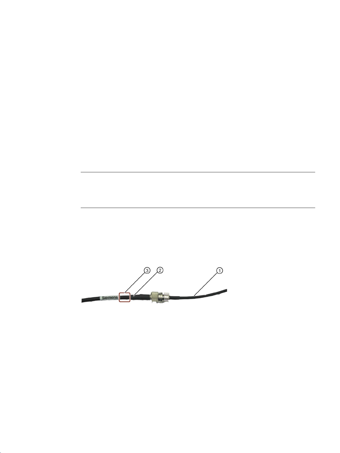
Strain relief
①
RF615A antenna connecting cable
②
RF600 antenna cable
③
Mounting point for strain relief
The SIMATIC RF615A antenna must be connected to the reader using an antenna cable.
Preassembled standard cables in lengths of 1 m, 3 m, 5 m, 10 m, 15 m, 20 m and 40 m are
available to connect the antenna.
The range of the antenna is limited by the cable loss. The maximum range can be achieved
with the cable 6GT2815-0BH10 (length 1 m), since this cable has the lowest cable loss.
To protect the antenna connecting cable from strain, you can attach strain relief, e.g. in the
form of a strain relief clamp. The following graphic shows the optimum mounting point for
attaching strain relief.
Figure 4-1 Strain relief
SIMATIC RF615A
Operating Instructions, 09/2018, C79000-G8976-C511-01
11
 Loading...