

Siemens SIMATIC RF600 System Manual

Answers for industry.
SIMATIC Ident
RFID SYSTEMS
SIMATIC RF600
System Manual · 05/2012


SIMATIC RF600
_
_________________
_
_
_________________
_
_
_________________
_
_
_________________
_
_
_________________
_
_
_________________
_
_
_________________
_
_
_________________
_
_
_________________
_
_
_________________
_
_
_________________
_
SIMATIC Ident
RFID systems
SIMATIC RF600
System Manual
05/2012
J31069-D0171-U001-A13-7618
Introduction
1
Safety Information
2
System overview
3
RF600 system planning
4
Readers
5
Antennas
6
Transponder/tags
7
Integration into networks
8
System diagnostics
9
Accessories
10
Appendix
A

Legal information
Legal information
Warning notice system
This manual contains notices you have to observe in order to ensure your personal safety, as well as to prevent
damage to property. The notices referring to your personal safety are highlighted in the manual by a safety alert
symbol, notices referring only to property damage have no safety alert symbol. These notices shown below are
graded according to the degree of danger.
DANGER
indicates that death or severe personal injury will result if proper precautions are not taken.
WARNING
indicates that death or severe personal injury may result if proper precautions are not taken.
CAUTION
with a safety alert symbol, indicates that minor personal injury can result if proper precautions are not taken.
CAUTION
without a safety alert symbol, indicates that property damage can result if proper precautions are not taken.
NOTICE
indicates that an unintended result or situation can occur if the relevant information is not taken into account.
If more than one degree of danger is present, the warning notice representing the highest degree of danger will
be used. A notice warning of injury to persons with a safety alert symbol may also include a warning relating to
property damage.
Qualified Personnel
The product/system described in this documentation may be operated only by personnel qualified for the specific
task in accordance with the relevant documentation, in particular its warning notices and safety instructions.
Qualified personnel are those who, based on their training and experience, are capable of identifying risks and
avoiding potential hazards when working with these products/systems.
Proper use of Siemens products
Note the following:
WARNING
Siemens products may only be used for the applications described in the catalog and in the relevant technical
documentation. If products and components from other manufacturers are used, these must be recommended
or approved by Siemens. Proper transport, storage, installation, assembly, commissioning, operation and
maintenance are required to ensure that the products operate safely and without any problems. The permissible
ambient conditions must be complied with. The information in the relevant documentation must be observed.
Trademarks
All names identified by ® are registered trademarks of Siemens AG. The remaining trademarks in this publication
may be trademarks whose use by third parties for their own purposes could violate the rights of the owner.
Disclaimer of Liability
We have reviewed the contents of this publication to ensure consistency with the hardware and software
described. Since variance cannot be precluded entirely, we cannot guarantee full consistency. However, the
information in this publication is reviewed regularly and any necessary corrections are included in subsequent
editions.
Siemens AG
Industry Sector
Postfach 48 48
90026 NÜRNBERG
GERMANY
Order number: J31069-D0171-U001
Ⓟ 05/2012 Technical data subject to change
Copyright © Siemens AG 2005, -,
2012.
All rights reserved

SIMATIC RF600
System Manual, 05/2012, J31069-D0171-U001-A13-7618
3
Table of contents
1 Introduction.............................................................................................................................................. 13
1.1
Preface.........................................................................................................................................13
1.2
Abbreviations and naming conventions .......................................................................................14
1.3
Navigating in the system manual.................................................................................................15
2
Safety Information.................................................................................................................................... 17
2.1
General safety instructions ..........................................................................................................17
2.2
Safety instructions for third-party antennas as well as for modifications to the RF600
system..........................................................................................................................................18
2.3
Safety distance to transmitter antenna ........................................................................................19
2.3.1
Safety distance between transmitter antenna and personnel......................................................19
2.3.2
Minimum distance to antenna in accordance with ETSI..............................................................20
2.3.3
Minimum distance to antenna in accordance with FCC (USA)....................................................21
3
System overview...................................................................................................................................... 23
3.1
RF System SIMATIC RF600........................................................................................................23
3.1.1
Application areas of RF600..........................................................................................................25
3.1.2
System components (hardware/software) ...................................................................................26
3.1.3
Features.......................................................................................................................................29
4
RF600 system planning........................................................................................................................... 31
4.1
Overview ......................................................................................................................................31
4.2
Possible system configurations....................................................................................................31
4.2.1
Scenario for material handling control .........................................................................................32
4.2.2
Scenario for workpiece identification ...........................................................................................34
4.2.3
Scenario for Intra logistics............................................................................................................36
4.2.4
Scenario incoming goods, distribution of goods and outgoing goods .........................................38
4.3
Antenna configurations ................................................................................................................39
4.3.1
Antenna configuration example ...................................................................................................39
4.3.2
Possibilities and application areas for antenna configurations....................................................41
4.3.3
Tag orientation in space...............................................................................................................45
4.3.4
Specified minimum and maximum spacing of antennas .............................................................45
4.3.5
Mutual interference of readers (antennas)...................................................................................48
4.3.6
Read and write range...................................................................................................................51
4.3.7
Static/dynamic mode....................................................................................................................52
4.3.8
Operation of several readers within restricted space ..................................................................52
4.3.8.1
Dense Reader Mode....................................................................................................................52
4.3.8.2
Optimizing tag reading accuracy .................................................................................................52
4.3.8.3
Optimization of robustness of tag data accesses for readers that are operated
simultaneously .............................................................................................................................53
4.3.8.4
Frequency hopping ......................................................................................................................53
4.3.9
Guidelines for selecting RFID UHF antennas..............................................................................54
4.3.9.1
Note safety information................................................................................................................54

Table of contents
SIMATIC RF600
4 System Manual, 05/2012, J31069-D0171-U001-A13-7618
4.3.9.2 Preconditions for selecting RFID UHF antennas ........................................................................ 54
4.3.9.3 General application planning....................................................................................................... 54
4.3.9.4
Antennas ..................................................................................................................................... 57
4.3.9.5
Antenna cables ........................................................................................................................... 68
4.3.9.6
Application example .................................................................................................................... 70
4.4
Environmental conditions for transponders/tags......................................................................... 71
4.5
The response of electromagnetic waves in the UHF band......................................................... 72
4.5.1
The effect of reflections and interference.................................................................................... 72
4.5.2
Influence of metals...................................................................................................................... 72
4.5.3
Influence of liquids and non-metallic substances........................................................................ 73
4.5.4
Influence of external components ............................................................................................... 73
4.6
Regulations applicable to frequency bands ................................................................................ 74
4.6.1
Regulations for UHF frequency bands in Europe ....................................................................... 74
4.6.2
Regulations for UHF frequency ranges in Argentina .................................................................. 75
4.6.3
Regulations for UHF frequency ranges in Bolivia ....................................................................... 75
4.6.4
Regulations for UHF frequency ranges in Brazil......................................................................... 75
4.6.5
Regulations for UHF frequency ranges in Canada ..................................................................... 75
4.6.6
Regulations for UHF frequency bands in China.......................................................................... 76
4.6.7
Regulations for UHF frequency ranges in India.......................................................................... 77
4.6.8
Regulations for UHF frequency ranges in Mexico ...................................................................... 77
4.6.9
Regulations for UHF frequency ranges in Russia....................................................................... 78
4.6.10
Regulations for UHF frequency bands in Singapore (866-869 MHz band) ................................ 79
4.6.11
Regulations for UHF frequency ranges in South Africa .............................................................. 79
4.6.12
Regulations for UHF frequency ranges in South Korea.............................................................. 80
4.6.13
Regulations for UHF frequency bands in Thailand ..................................................................... 81
4.6.14
Regulations for UHF frequency bands in the USA ..................................................................... 81
4.7
Guidelines for electromagnetic compatibility (EMC) ................................................................... 82
4.7.1
Overview ..................................................................................................................................... 82
4.7.2
What does EMC mean?.............................................................................................................. 82
4.7.3
Basic rules................................................................................................................................... 83
4.7.4
Propagation of electromagnetic interference .............................................................................. 85
4.7.5
Prevention of interference sources ............................................................................................. 87
4.7.6
Equipotential bonding.................................................................................................................. 88
4.7.7
Cable shielding............................................................................................................................ 89
5
Readers................................................................................................................................................... 93
5.1
RF620R reader ........................................................................................................................... 94
5.1.1
Description .................................................................................................................................. 94
5.1.1.1
Ordering data .............................................................................................................................. 95
5.1.1.2
Status display.............................................................................................................................. 97
5.1.1.3
Pin assignment of the RS422 interface....................................................................................... 98
5.1.1.4
Pin assignment of the connecting cable ..................................................................................... 98
5.1.1.5
Grounding connection ................................................................................................................. 99
5.1.2
Planning application.................................................................................................................... 99
5.1.2.1
Minimum mounting clearances of two readers ........................................................................... 99
5.1.2.2
Antenna diagram for RF620R (ETSI)........................................................................................ 100
5.1.2.3
Antenna diagram for RF620R (FCC) ........................................................................................ 103
5.1.2.4
Interpretation of directional radiation patterns........................................................................... 106
5.1.2.5
Antenna/read point configurations ............................................................................................ 106
5.1.3
Installing/Mounting .................................................................................................................... 107

Table of contents
SIMATIC RF600
System Manual, 05/2012, J31069-D0171-U001-A13-7618
5
5.1.3.1 Mounting/Installing FCC.............................................................................................................107
5.1.4 Configuration/integration............................................................................................................108
5.1.4.1
Transmission protocols ..............................................................................................................109
5.1.5
Technical data............................................................................................................................109
5.1.5.1
Mechanical data.........................................................................................................................109
5.1.5.2
Technical data according to EPC and ISO ................................................................................111
5.1.5.3
Maximum number of readable tags ...........................................................................................112
5.1.6
Dimension drawings...................................................................................................................113
5.1.7
Certificates and approvals .........................................................................................................114
5.1.7.1
Country-specific certifications ....................................................................................................114
5.1.7.2
FCC information.........................................................................................................................115
5.1.7.3
IC-FCB information ....................................................................................................................116
5.2
RF630R reader ..........................................................................................................................117
5.2.1
Description .................................................................................................................................117
5.2.1.1
Ordering data .............................................................................................................................118
5.2.1.2
Status display.............................................................................................................................119
5.2.1.3
Pin assignment of the RS422 interface .....................................................................................120
5.2.1.4
Pin assignment of the connecting cable ....................................................................................121
5.2.1.5
Grounding connection................................................................................................................121
5.2.2
Planning application...................................................................................................................122
5.2.2.1
Minimum mounting clearances of two antennas of different readers ........................................122
5.2.2.2
Antenna/read point configurations .............................................................................................122
5.2.3
Installing/Mounting .....................................................................................................................123
5.2.3.1
Mounting/Installation ..................................................................................................................123
5.2.4
Configuration/integration............................................................................................................124
5.2.4.1
Transmission protocols ..............................................................................................................125
5.2.5
Technical data............................................................................................................................125
5.2.5.1
Mechanical data.........................................................................................................................125
5.2.5.2
Technical data according to EPC and ISO ................................................................................127
5.2.5.3
Maximum number of readable tags ...........................................................................................128
5.2.6
Dimension drawings...................................................................................................................129
5.2.7
Certificates and approvals .........................................................................................................130
5.2.7.1
FCC information.........................................................................................................................131
5.2.7.2
IC-FCB information ....................................................................................................................132
5.3
RF640R reader ..........................................................................................................................133
5.3.1
Description .................................................................................................................................133
5.3.1.1
Overview ....................................................................................................................................133
5.3.1.2
Ordering data .............................................................................................................................134
5.3.1.3
Status display.............................................................................................................................136
5.3.1.4
Pin assignment of the digital I/O interface .................................................................................137
5.3.1.5
Connection scheme for the digital I/O interface.........................................................................138
5.3.1.6
Pin assignment for power supply...............................................................................................143
5.3.1.7
Pin assignment for Industrial Ethernet interface........................................................................144
5.3.1.8
Grounding connection................................................................................................................144
5.3.2
Planning the use ........................................................................................................................145
5.3.2.1
Selecting the antenna ................................................................................................................145
5.3.2.2
Internal antenna .........................................................................................................................145
5.3.2.3
External antenna........................................................................................................................153
5.3.3
Installing / mounting ...................................................................................................................153
5.3.4
Configuration/integration............................................................................................................154
5.3.5
Technical data............................................................................................................................155

Table of contents
SIMATIC RF600
6 System Manual, 05/2012, J31069-D0171-U001-A13-7618
5.3.5.1 Mechanical data ........................................................................................................................ 155
5.3.5.2 Technical data according to EPC and ISO ............................................................................... 157
5.3.6
Dimension drawings.................................................................................................................. 158
5.3.7
Certificates and approvals......................................................................................................... 159
5.3.7.1
FCC information ........................................................................................................................ 160
5.3.7.2
IC-FCB information ................................................................................................................... 160
5.4
RF670R reader ......................................................................................................................... 162
5.4.1
Description ................................................................................................................................ 162
5.4.1.1
Overview ................................................................................................................................... 162
5.4.1.2
Ordering data ............................................................................................................................ 163
5.4.1.3
Status display............................................................................................................................ 165
5.4.1.4
Pin assignment of the digital I/O interface ................................................................................ 166
5.4.1.5
Connection scheme for the digital I/O interface........................................................................ 166
5.4.1.6
Pin assignment for power supply.............................................................................................. 171
5.4.1.7
Pin assignment for Industrial Ethernet interface....................................................................... 172
5.4.1.8
Grounding connection ............................................................................................................... 172
5.4.2
Planning the use ....................................................................................................................... 173
5.4.2.1
Antenna/read point configurations ............................................................................................ 173
5.4.3
Installing / mounting .................................................................................................................. 174
5.4.4
Configuration/integration........................................................................................................... 174
5.4.4.1
Configuration............................................................................................................................. 174
5.4.5
Technical data........................................................................................................................... 176
5.4.5.1
Mechanical data ........................................................................................................................ 176
5.4.5.2
Technical data according to EPC and ISO ............................................................................... 178
5.4.6
Dimension drawings.................................................................................................................. 179
5.4.7
Certificates and approvals......................................................................................................... 180
5.4.7.1
FCC information ........................................................................................................................ 182
5.4.7.2
IC-FCB information ................................................................................................................... 183
5.5
Reader RF680M........................................................................................................................ 184
5.5.1
Description ................................................................................................................................ 184
5.5.2
Field of application and features ............................................................................................... 184
6
Antennas ............................................................................................................................................... 187
6.1
Overview ................................................................................................................................... 187
6.2
RF620A antenna ....................................................................................................................... 189
6.2.1
Description ................................................................................................................................ 189
6.2.2
Ordering data ............................................................................................................................ 190
6.2.3
Installation and assembly.......................................................................................................... 190
6.2.3.1
RF620A mounting types............................................................................................................ 190
6.2.4
Connecting an antenna to the reader ....................................................................................... 190
6.2.4.1
Overview ................................................................................................................................... 190
6.2.4.2
Connecting RF620A to an RF600 reader ................................................................................. 192
6.2.5
Parameter settings of RF620A for RF620R/RF630R ............................................................... 192
6.2.6
Parameter settings of RF620A for RF640R/RF670R ............................................................... 193
6.2.7
Alignment of transponders to the antenna................................................................................ 194
6.2.8
Antenna patterns....................................................................................................................... 197
6.2.8.1
Antenna pattern ETSI................................................................................................................ 197
6.2.8.2
Antenna pattern FCC ................................................................................................................ 200
6.2.8.3
Interpretation of directional radiation patterns........................................................................... 203
6.2.9
Read/write ranges ..................................................................................................................... 203
6.2.10
Technical data........................................................................................................................... 207

Table of contents
SIMATIC RF600
System Manual, 05/2012, J31069-D0171-U001-A13-7618
7
6.2.11 Dimension drawing ....................................................................................................................208
6.2.12 Approvals & certificates .............................................................................................................209
6.3
Antenna RF640A .......................................................................................................................210
6.3.1
Description .................................................................................................................................210
6.3.2
Ordering data .............................................................................................................................211
6.3.3
Installation and assembly...........................................................................................................211
6.3.3.1
RF640A mounting types ............................................................................................................211
6.3.3.2
RF640A mounting types ............................................................................................................212
6.3.4
Connecting an antenna to the reader ........................................................................................212
6.3.4.1
Bending radii and bending cycles of the cable ..........................................................................213
6.3.5
Parameter settings of RF640A for RF620R/RF630R ................................................................214
6.3.6
Parameter settings of RF640A for RF640R/RF670R ................................................................215
6.3.7
Antenna patterns........................................................................................................................217
6.3.7.1
Antenna radiation patterns in the ETSI frequency band............................................................217
6.3.7.2
Antenna radiation patterns in the FCC frequency band ............................................................222
6.3.7.3
Interpretation of directional radiation patterns ...........................................................................226
6.3.8
Technical data............................................................................................................................227
6.3.9
Dimension drawing ....................................................................................................................229
6.3.10
Approvals & certificates .............................................................................................................230
6.4
Antenna RF642A .......................................................................................................................231
6.4.1
Description .................................................................................................................................231
6.4.2
Ordering data .............................................................................................................................232
6.4.3
Installation and assembly...........................................................................................................232
6.4.3.1
RF640A mounting types ............................................................................................................232
6.4.4
Connecting an antenna to the reader ........................................................................................233
6.4.4.1
Bending radii and bending cycles of the cable ..........................................................................234
6.4.5
Alignment of transponders to the antenna.................................................................................235
6.4.6
Parameter settings of RF642A for RF620R/RF630R ................................................................238
6.4.7
Parameter settings of RF642A for RF640R/RF670R ................................................................239
6.4.8
Antenna patterns........................................................................................................................240
6.4.8.1
Antenna radiation patterns in the ETSI frequency band............................................................240
6.4.8.2
Antenna radiation patterns in the FCC frequency band ............................................................242
6.4.8.3
Interpretation of directional radiation patterns ...........................................................................244
6.4.9
Technical data............................................................................................................................244
6.4.10
Dimension drawing ....................................................................................................................246
6.4.11
Approvals & certificates .............................................................................................................247
6.5
RF660A antenna........................................................................................................................248
6.5.1
Description .................................................................................................................................248
6.5.2
Installation and assembly...........................................................................................................249
6.5.2.1
RF660A mounting types ............................................................................................................249
6.5.3
Connecting an antenna to a reader ...........................................................................................250
6.5.3.1
Bending radii and bending cycles of the cable ..........................................................................251
6.5.4
Parameter settings of RF660A for RF620R/RF630R ................................................................251
6.5.5
Parameter settings of RF660A for RF640R/RF670R ................................................................252
6.5.6
Antenna patterns........................................................................................................................253
6.5.6.1
Antenna pattern .........................................................................................................................253
6.5.7
Interpretation of directional radiation patterns ...........................................................................256
6.5.8
Technical data............................................................................................................................257
6.5.9
Dimension drawing ....................................................................................................................258
6.5.10
Approvals & certificates .............................................................................................................259
6.5.10.1
CE mark .....................................................................................................................................259

Table of contents
SIMATIC RF600
8 System Manual, 05/2012, J31069-D0171-U001-A13-7618
6.5.10.2 FCC approvals .......................................................................................................................... 260
6.6 Mounting types.......................................................................................................................... 261
6.6.1
Overview ................................................................................................................................... 261
6.6.2
Ordering data ............................................................................................................................ 261
6.6.3
Mounting with antenna mounting kit ......................................................................................... 262
7
Transponder/tags................................................................................................................................... 265
7.1
Overview ................................................................................................................................... 265
7.1.1
Tags in different sizes and types .............................................................................................. 265
7.1.2
Mode of operation of transponders/tags ................................................................................... 266
7.1.3
Transponder classes and generations...................................................................................... 266
7.1.4
Electronic Product Code (EPC) ................................................................................................ 268
7.1.5
SIMATIC memory configuration of the RF600 transponders and labels .................................. 270
7.2
SIMATIC RF630L Smartlabel.................................................................................................... 277
7.2.1
Features .................................................................................................................................... 277
7.2.2
Ordering data ............................................................................................................................ 278
7.2.3
Minimum spacing between labels ............................................................................................. 278
7.2.4
Memory configuration of the smart label................................................................................... 279
7.2.5
Technical data........................................................................................................................... 279
7.2.6
Dimension drawings.................................................................................................................. 282
7.3
SIMATIC RF680L Smartlabel.................................................................................................... 284
7.3.1
Features .................................................................................................................................... 284
7.3.2
Delivery format .......................................................................................................................... 285
7.3.3
Ordering data ............................................................................................................................ 285
7.3.4
Minimum spacing between labels ............................................................................................. 286
7.3.5
Memory configuration of the smart label................................................................................... 286
7.3.6
Mounting on metal..................................................................................................................... 287
7.3.7
Technical data........................................................................................................................... 288
7.3.7.1
Mechanical data ........................................................................................................................ 288
7.3.7.2
Electrical data............................................................................................................................ 288
7.3.7.3
Memory specifications............................................................................................................... 289
7.3.7.4
Environmental conditions.......................................................................................................... 289
7.3.8
Certificates and approvals......................................................................................................... 289
7.3.9
Dimension drawing.................................................................................................................... 290
7.4
SIMATIC RF610T...................................................................................................................... 291
7.4.1
Features .................................................................................................................................... 291
7.4.2
Ordering data ............................................................................................................................ 292
7.4.3
Safety instructions for the device/system.................................................................................. 292
7.4.4
Minimum spacing between labels ............................................................................................. 292
7.4.5
Memory configuration of the transponder ................................................................................. 293
7.4.6
Technical data........................................................................................................................... 293
7.4.6.1
Mechanical data ........................................................................................................................ 293
7.4.6.2
Electrical data............................................................................................................................ 293
7.4.6.3
Memory specifications............................................................................................................... 294
7.4.6.4
Environmental conditions.......................................................................................................... 294
7.4.7
Certificates and approvals......................................................................................................... 295
7.4.8
Dimension drawing.................................................................................................................... 295
7.5
SIMATIC RF620T...................................................................................................................... 296
7.5.1
Characteristics .......................................................................................................................... 296
7.5.2
Ordering data ............................................................................................................................ 297

Table of contents
SIMATIC RF600
System Manual, 05/2012, J31069-D0171-U001-A13-7618
9
7.5.3 Planning the use ........................................................................................................................297
7.5.3.1 Reading range when mounted on non-metallic carriers ............................................................297
7.5.3.2
Directional radio pattern of the transponder on non-metallic surfaces......................................297
7.5.3.3
Optimum antenna/transponder positioning with planar mounting of the transponder on
metal ..........................................................................................................................................300
7.5.3.4
Reading range when mounted on flat metallic carrier plates.....................................................301
7.5.3.5
Influence of conducting walls on the reading range...................................................................301
7.5.3.6
Directional radio pattern of the transponder on metallic surfaces .............................................303
7.5.3.7
Reading range when mounted on ESD carrier materials ..........................................................304
7.5.3.8
Communication with multiple transponders ...............................................................................306
7.5.4
Mounting instructions.................................................................................................................307
7.5.5
Memory configuration of the transponder ..................................................................................308
7.5.6
Technical Specifications ............................................................................................................308
7.5.6.1
Mechanical data.........................................................................................................................308
7.5.6.2
Electrical data.............................................................................................................................308
7.5.6.3
Memory specifications ...............................................................................................................309
7.5.6.4
Environmental conditions...........................................................................................................309
7.5.6.5
Chemical resistance of the transponder RF620T ......................................................................310
7.5.7
Certificates and approvals .........................................................................................................313
7.5.8
Dimension drawing ....................................................................................................................314
7.6
SIMATIC RF625T ......................................................................................................................315
7.6.1
Characteristics ...........................................................................................................................315
7.6.2
Ordering data .............................................................................................................................315
7.6.3
Planning the use ........................................................................................................................316
7.6.3.1
Optimum antenna/transponder positioning with planar mounting of the transponder on
metal ..........................................................................................................................................316
7.6.3.2
Reading range when mounted on flat metallic carrier plates.....................................................317
7.6.3.3
Reading range when mounted on non-metallic carrier materials ..............................................318
7.6.3.4
Influence of conducting walls on the reading range...................................................................318
7.6.3.5
Mounting in metal.......................................................................................................................319
7.6.3.6
Directional radiation pattern of the transponder.........................................................................320
7.6.4
Mounting instructions.................................................................................................................323
7.6.5
Memory configuration of the transponder ..................................................................................323
7.6.6
Technical Specifications ............................................................................................................323
7.6.6.1
Mechanical data.........................................................................................................................323
7.6.6.2
Electrical data.............................................................................................................................324
7.6.6.3
Information on memory..............................................................................................................324
7.6.6.4
Environmental conditions...........................................................................................................325
7.6.6.5
Chemical resistance of the RF625T transponder ......................................................................325
7.6.7
Certificates and approvals .........................................................................................................326
7.6.8
Dimension drawing ....................................................................................................................327
7.7
SIMATIC RF630T ......................................................................................................................328
7.7.1
Characteristics ...........................................................................................................................328
7.7.2
Ordering data .............................................................................................................................329
7.7.3
Planning application...................................................................................................................329
7.7.3.1
Optimum antenna/transponder positioning with plane mounting of the transponder on
metal ..........................................................................................................................................329
7.7.3.2
Reading range when mounted on flat metallic carrier plates.....................................................332
7.7.3.3
Influence of conducting walls on the reading range...................................................................332
7.7.3.4
Directional radiation pattern of the transponder.........................................................................334
7.7.4
Mounting instructions.................................................................................................................335

Table of contents
SIMATIC RF600
10 System Manual, 05/2012, J31069-D0171-U001-A13-7618
7.7.5 Memory configuration of the transponder ................................................................................. 335
7.7.6 Technical specifications ............................................................................................................ 336
7.7.6.1
Mechanical data ........................................................................................................................ 336
7.7.6.2
Electrical data............................................................................................................................ 336
7.7.6.3
Memory specifications............................................................................................................... 337
7.7.6.4
Environmental conditions.......................................................................................................... 337
7.7.6.5
Chemical resistance of the transponder ................................................................................... 338
7.7.7
Certificates and approvals......................................................................................................... 339
7.7.8
Dimension drawing.................................................................................................................... 340
7.8
SIMATIC RF640T Gen 2........................................................................................................... 341
7.8.1
Characteristics .......................................................................................................................... 341
7.8.2
Ordering data ............................................................................................................................ 342
7.8.3
Planning the use ....................................................................................................................... 342
7.8.3.1
Optimum antenna/transponder positioning with plane mounting of the transponder on
metal.......................................................................................................................................... 342
7.8.3.2
Reading range when mounted on flat metallic carrier plates.................................................... 343
7.8.3.3
Reading range when mounted on non-metallic carriers ........................................................... 344
7.8.3.4
Influence of conducting walls on the reading range.................................................................. 344
7.8.3.5
Directional radiation pattern of the transponder........................................................................ 345
7.8.3.6
Use of the transponder in the Ex protection area ..................................................................... 347
7.8.3.7
Use of the transponder in hazardous areas for gases.............................................................. 347
7.8.3.8
Use of the transponder in hazardous areas for dusts............................................................... 348
7.8.3.9
Use of the transponder in the Ex protection area ..................................................................... 349
7.8.3.10
Use of the transponder in hazardous areas for gases.............................................................. 349
7.8.3.11
Use of the transponder in hazardous areas for dusts............................................................... 352
7.8.4
Mounting instructions ................................................................................................................ 354
7.8.5
Memory configuration of the transponder ................................................................................. 354
7.8.6
Technical Specifications............................................................................................................ 355
7.8.6.1
Mechanical data ........................................................................................................................ 355
7.8.6.2
Electrical data............................................................................................................................ 355
7.8.6.3
Memory specifications............................................................................................................... 356
7.8.6.4
Environmental conditions.......................................................................................................... 356
7.8.6.5
Chemical resistance of the RF640T transponder ..................................................................... 357
7.8.7
Certificates and approvals......................................................................................................... 359
7.8.7.1
Manufacturer's declaration RF640T Gen 2 UHF Tool Tag Version 1....................................... 359
7.8.8
Dimension drawing.................................................................................................................... 360
7.9
SIMATIC RF680T...................................................................................................................... 361
7.9.1
Characteristics .......................................................................................................................... 361
7.9.2
Ordering data ............................................................................................................................ 362
7.9.3
Planning the use ....................................................................................................................... 362
7.9.3.1
Reading range when mounted on non-metallic carriers ........................................................... 363
7.9.3.2
Directional radiation pattern of the transponder on non-metallic surfaces ............................... 364
7.9.3.3
Optimum antenna/transponder positioning with plane mounting of the transponder on
metal.......................................................................................................................................... 366
7.9.3.4
Reading range when mounted on plane metallic carrier plates................................................ 367
7.9.3.5
Influence of conducting walls on the reading range.................................................................. 367
7.9.3.6
Directional radiation pattern of the transponder on metallic surfaces....................................... 370
7.9.4
Mounting instructions ................................................................................................................ 371
7.9.5
Memory configuration of the transponder ................................................................................. 371
7.9.6
Technical specifications ............................................................................................................ 372
7.9.6.1
Mechanical data ........................................................................................................................ 372

Table of contents
SIMATIC RF600
System Manual, 05/2012, J31069-D0171-U001-A13-7618
11
7.9.6.2 Electrical data.............................................................................................................................372
7.9.6.3 Memory specifications ...............................................................................................................373
7.9.6.4
Environmental conditions...........................................................................................................373
7.9.6.5
Chemical resistance of the RF680T transponder ......................................................................374
7.9.7
Certificates and approvals .........................................................................................................375
7.9.8
Dimension drawing ....................................................................................................................375
8
Integration into networks........................................................................................................................ 377
8.1
Overview of parameterization of RF600 reader.........................................................................377
8.2
Integration in IT networks via the user application.....................................................................377
8.3
Integration in SIMATIC networks ...............................................................................................378
9
System diagnostics................................................................................................................................ 385
9.1
Flashing codes of the RF600 readers with Ethernet interface...................................................385
9.2
Error messages RF600 reader ..................................................................................................385
9.3
Error messages and flash codes for RF620R/RF630R .............................................................386
10
Accessories ........................................................................................................................................... 393
10.1
Wide-range power supply unit for SIMATIC RF systems ..........................................................393
10.1.1
Features.....................................................................................................................................393
10.1.2
Scope of supply .........................................................................................................................394
10.1.3
Ordering data .............................................................................................................................394
10.1.4
Safety Information......................................................................................................................395
10.1.5
Connecting.................................................................................................................................396
10.1.6
Technical specifications .............................................................................................................397
10.1.7
Pin assignment of DC outputs and mains connection...............................................................399
10.1.8
Dimension drawing ....................................................................................................................400
10.1.9
Certificates and approvals .........................................................................................................401
A
Appendix................................................................................................................................................ 403
A.1
Certificates and approvals .........................................................................................................403
A.2
Service & support.......................................................................................................................405
Glossary ................................................................................................................................................ 407
Index...................................................................................................................................................... 421

Table of contents
SIMATIC RF600
12 System Manual, 05/2012, J31069-D0171-U001-A13-7618

SIMATIC RF600
System Manual, 05/2012, J31069-D0171-U001-A13-7618
13
Introduction
1
1.1 Preface
Purpose of this document
This system manual contains the information needed to plan and configure the RF600
system.
It is intended both for programming and testing/debugging personnel who commission the
system themselves and connect it with other units (automation systems, further
programming devices), as well as for service and maintenance personnel who install
expansions or carry out fault/error analyses.
Scope of this documentation
This documentation is valid for all supplied variants of the SIMATIC RF600 system and
describes the products supplied as of May 2012. If you are using older firmware versions,
please refer to the 08/2011 edition of the documentation.
Registered trademarks
SIMATIC ® is a registered trademark of the Siemens AG.
History
Edition Comment
11/2005 First edition
03/2006 2nd revised edition
04/2006 3rd revised and extended edition
Details in the technical descriptions were revised.
06/2006 4th revised and extended edition
07/2008 5th revised and extended edition
11/2008 6th revised and extended edition:
new RF620R and RF630R readers
07/2009 7th revised and extended edition:
FCC approval RF620R/RF630R
10/2009 8th revised and expanded edition for multitag mode
12/2009 9th revised and extended edition
06/2010 10th revised and extended edition
09/2010 11th revised edition

Introduction
1.2 Abbreviations and naming conventions
SIMATIC RF600
14 System Manual, 05/2012, J31069-D0171-U001-A13-7618
Edition Comment
08/2011 12th revised and expanded edition
New reader RF640R, new antennas RF640A and RF642A
05/2012 13th revised and extended edition
Declaration of conformity
The EC declaration of conformity and the corresponding documentation are made available
to authorities in accordance with EC directives. Your sales representative can provide these
on request.
Observance of installation guidelines
The installation guidelines and safety instructions given in this documentation must be
followed during commissioning and operation.
1.2 Abbreviations and naming conventions
The following terms/abbreviations are used synonymously in this document:
Read/write device (SLG) Reader
Mobile data memory, MDS, data carrier,
smart label
Transponder, tag
Interface module, ASM Communications module, CM

Introduction
1.3 Navigating in the system manual
SIMATIC RF600
System Manual, 05/2012, J31069-D0171-U001-A13-7618
15
1.3 Navigating in the system manual
Structure of contents Contents
Table of contents Organization of the documentation, including the index of pages and sections
Introduction Purpose, layout and description of the important topics.
Safety Information Refers to all the valid technical safety aspects which have to be adhered to while installing,
commissioning and operating the product/system and with reference to statutory
regulations.
System overview Overview of all RF identification systems, system overview of SIMATIC RF600.
RF600 system planning Information about possible applications of SIMATIC RF600, support for application
planning, tools for finding suitable SIMATIC RF600 components.
Readers Description of readers which can be used for SIMATIC RF600.
Antennas Description of antennas which can be used for SIMATIC RF600.
Transponder/tags Description of transponders which can be used for SIMATIC RF600.
Integration into networks Integration of the RF600 reader to higher-level systems, control.
System diagnostics Description of the flash codes and error codes of the reader.
Accessories Connecting cable, wide-range power supply unit, technical data, ordering lists, dimension
drawings
Appendix Service and support, contact partners, training centers.
List of abbreviations List of all abbreviations used in the document.

Introduction
1.3 Navigating in the system manual
SIMATIC RF600
16 System Manual, 05/2012, J31069-D0171-U001-A13-7618
SIMATIC RF600
System Manual, 05/2012, J31069-D0171-U001-A13-7618
17
Safety Information
2
2.1 General safety instructions
CAUTION
Please observe the safety instructions on the back cover of this documentation.
SIMATIC RFID products comply with the salient safety specifications to VDE/DIN, IEC, EN,
UL and CSA. If you have questions about the admissibility of the installation in the
designated environment, please contact your service representative.
CAUTION
Alterations to the devices are not permitted.
Failure to observe this requirement shall constitute a revocation of the radio equipment
approval, CE approval and manufacturer's warranty.
Repairs
Repairs may only be carried out by authorized qualified personnel.
WARNING
Unauthorized opening of and improper repairs to the device may result in substantial
damage to equipment or risk of personal injury to the user.
System expansion
Only install system expansion devices designed for this device. If you install other upgrades,
you may damage the system or violate the safety requirements and regulations for radio
frequency interference suppression. Contact your technical support team or where you
purchased your device to find out which system expansion devices may safely be installed.
CAUTION
If you cause system defects by improperly installing or exchanging system expansion
devices, the warranty becomes void.

Safety Information
2.2 Safety instructions for third-party antennas as well as for modifications to the RF600 system
SIMATIC RF600
18 System Manual, 05/2012, J31069-D0171-U001-A13-7618
2.2 Safety instructions for third-party antennas as well as for
modifications to the RF600 system
Always observe the following general safety instructions before selecting a component from
a different vendor:
The manufacturer accepts no responsibility for functional suitability or legal implications for
the installation of third-party components.
NOTICE
Loss of radio equipment approvals
A
lterations to the SIMATIC RF600 devices themselves are not permitted. Failure to observe
this requirement shall constitute a revocation of the CE, FCC, UL, CSA radio equipment
approvals and the manufacturer's warranty.
Modifications to the SIMATIC RF600 system
CAUTION
Damage to the system
If you install unsuitable or unapproved extensions, you may damage the system or violate
the safety requirements and regulations for radio frequency interference suppression.
Contact your technical support team or where you purchased your device to find out which
system extensions may safely be installed.
CAUTION
Loss of warranty
If you cause defects on the SIMATIC RF600 system by improperly installing or exchanging
system expansions, the warranty becomes void.
NOTICE
Loss of validity for type tests and certificates
SIMATIC RFID products comply with the salient safety specifications to VDE/DIN, IEC, EN,
UL and CSA. When using RFID components which do not belong to the RF600 range of
products, the validity of all type tests as well as all certificates relevant to the RF600 are
canceled: CE, FCC, UL, CSA.

Safety Information
2.3 Safety distance to transmitter antenna
SIMATIC RF600
System Manual, 05/2012, J31069-D0171-U001-A13-7618
19
Note
User responsibility for modified product
As a user of the modified product, you accept responsibility for use of the complete RFID
product comprising both SIMATIC RF600 components and third-party RFID components.
This particularly applies to modification or replacement of:
• Antennas
• Antenna cables
• readers
• Power supply units with connection cables
2.3 Safety distance to transmitter antenna
2.3.1 Safety distance between transmitter antenna and personnel
For antenna configurations where it is possible to be briefly or constantly within the
transmission range of the antennas, as in loading ramps, for example, minimum distances
must be maintained.
Limits
The ICRP (International Commission of Radiological Protection) has worked out limit values
for human exposure to HF fields that are also recommended by the ICNIRP (International
Commission of Non Ionizing Radiological Protection). In German legislation on emissions
(since 1997), the following limit values apply. These can vary according to frequency:
Frequency f [MHz] Electrical field strength E [V/m] Magnetic field strength H [A/m]
10 - 400 27,5 0,073
400 - 2.000 1.375 x f
1/2
0.0037 x f
1/2
2.000 - 300.000 61 0,16
The limit values for the 900 MHz reader antenna alternating field are thus:
Electrical field strength: E = 41.25 V/m
Magnetic field strength: H = 0.111 A/m
HF power density: E x H = 4.57 W/m
2
Safety Information
2.3 Safety distance to transmitter antenna
SIMATIC RF600
20 System Manual, 05/2012, J31069-D0171-U001-A13-7618
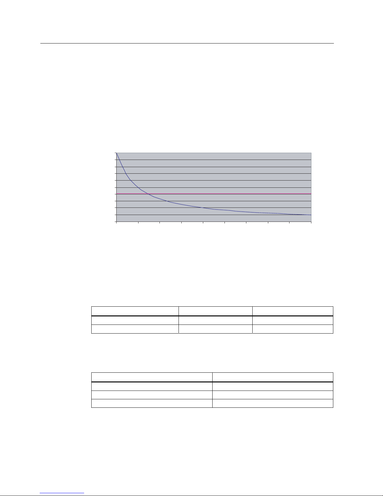
2.3.2 Minimum distance to antenna in accordance with ETSI
Minimum distance to antenna in accordance with ETSI (EU, EFTA, Turkey)
At a transmission frequency of 900 MHz, the wavelength of the electromagnetic wave λ is
approximately 0.34 m. For distances less than 1 λ in the near field, the electrical field
strength (1/r) diminishes exponentially to the power three over distance, and for distances
greater than 1 λ, it diminishes exponentially to the power two over distance.
0
10
20
30
40
50
60
70
80
90
100
0,1 0,2 0,3 0,4 0,5 0,6 0,7 0.8 0.9 1
(OHFWULFDOILHOGVWUHQJWKDWDGLVWDQFHIURPWKH7;DQWHQQDIRU3 :(53
'LVWDQFHP
)LHOGVWUHQJWK9P
The horizontal line at 41.25V/m marks the "safety limit value".
For the maximum permissible transmit power (1/r
2
) in accordance with ETSI (2W ERP), the
"safety distance" d = 0.24 m. This means that personnel should not remain closer than 24cm
to the transmitter antenna for extended periods (more than several hours without
interruption). Remaining within the vicinity of the antenna for a brief period, even for repeated
periods (at a distance < 0.24 m), is harmless according to current knowledge.
Distance to transmitter antenna [m] Feld strength [V/m] % of limit value
1 10 24
5 2 5
If the transmitter power is set lower than the highest permissible value (2 watts ERP), the
"safety distance" reduces correspondingly.
The values for this are as follows:
Radiated power ERP [W] Safety distance to transmitter antenna [m]
2.0 0.24
1.0 0.17
0.5 0.12
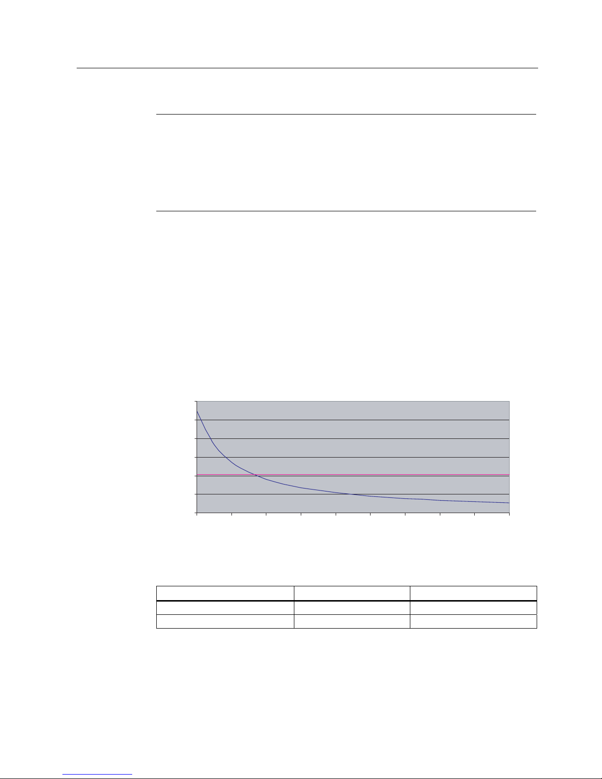
Safety Information
2.3 Safety distance to transmitter antenna
SIMATIC RF600
System Manual, 05/2012, J31069-D0171-U001-A13-7618
21
Note
Reduced maximum radiated power with RF620R/RF630R readers
The SIMATIC RF620R (ETSI) reader has a maximum radiated power of 0.5 W ERP. The
maximum safety distance is therefore 0.12 m.
The SIMATIC RF630R (ETSI) reader has a maximum transmitter power of 0.5 W. The
radiated power therefore depends on the antenna cable and the type of antenna used, but
must not exceed the 2 W ERP.
2.3.3 Minimum distance to antenna in accordance with FCC (USA)
Minimum distance to antenna in accordance with FCC (USA)
For the maximum permissible radiated power in accordance with FCC (4W EIRP), the
"safety distance" d = 0.26 m. This means that personnel should not remain closer than 26
cm to the transmitter antenna for extended periods (several hours without interruption).
Remaining within the vicinity of the antenna for brief period, even repeated periods (at a
distance < 0.26 m) is harmless to health according to current knowledge.
0
20
40
60
80
100
120
0.1 0.2 0.3 0.4 0.5 0.6 0.7 0.8 0.9 1
(OHFWULFDOILHOGVWUHQJWKDWDGLVWDQFHIURPWKH7;DQWHQQDIRU3 :(,53
'LVWDQFHP
)LHOGVWUHQJWK9P
The horizontal line at 41.25 V/m marks the "safety limit value".
Distance to transmitter antenna [m] Feld strength [V/m] % of limit value
1 10.9 26
5 2.2 5.3
If the transmit power is set lower than the highest permissible value (4 watts EIRP), the
"safety distance" reduces correspondingly.
The values for this are as follows:

Safety Information
2.3 Safety distance to transmitter antenna
SIMATIC RF600
22 System Manual, 05/2012, J31069-D0171-U001-A13-7618
Radiated power EIRP [W] Safety distance to transmitter antenna [m]
4.0 0.26
<2.5 >0.20
Generally a safety distance of at least 0.2 m must be maintained.
Note
Reduced maximum radiated power with RF620R/RF630R readers
The SIMATIC RF620R (FCC) reader has a maximum transmit power of 0.5 W. Thus the
radiated power of 4 W EIRP cannot be exceeded with the internal antenna.
The SIMATIC RF630R (FCC) reader has a maximum transmit power of 0.5 W. The radiated
power therefore depends on the antenna cable and the type of antenna used, but must not
exceed the 4 W EIRP.

SIMATIC RF600
System Manual, 05/2012, J31069-D0171-U001-A13-7618
23
System overview
3
3.1 RF System SIMATIC RF600
SIMATIC RF600 is an identification system that operates in the UHF range. UHF technology
supports large write/read distances with passive tags.
The SIMATIC RF670R readers (write/read devices), fitted for example on the gates of a
warehouse, automatically record every movement of goods, and signal these to the higherlevel systems. The data are filtered and compressed there by data management software at
the control level in order, for example, to generate the receiving department transaction for
the ERP (Enterprise Resource Planning) system at the business administration control level.
At the same time, the delivery can be automatically checked for correctness and
completeness prior to storage by means of the electronic delivery list.
The general automation and IT structure of a company is shown in the following figure. This
comprises several different levels that are described in detail below.
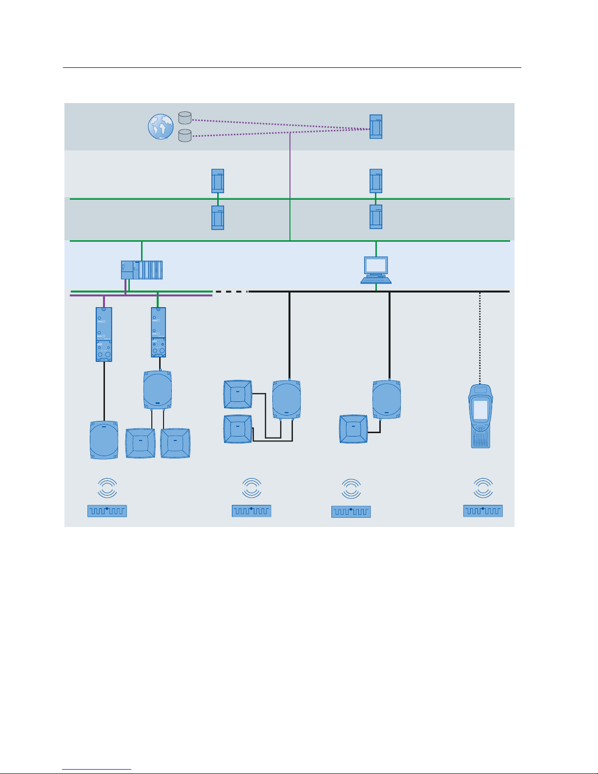
System overview
3.1 RF System SIMATIC RF600
SIMATIC RF600
24 System Manual, 05/2012, J31069-D0171-U001-A13-7618
5)5
5)5
5)5
ONS oder EDI
2EMHFW1DPH6HUYLFH
(OHFWURQLF'DWD,QWHUFKDQJH
Acquisition level
Global Integration
Business administration
control
Production control
SCM
6XSSO\&KDLQ
0DQDJHPHQW
MES
0DQXIDFWXULQJ
([HFXWLRQ6\VWHP
WMS
:DUHKRXVH
0DQDJHPHQW6\VWHP
ERP
(QWHUSULVH5HVRXUFH
3ODQQLQJ
RFID Data & Device
Management
6,0$7,&5)0$1$*(5
mobile handheld
terminals
6,0$7,&5)0
SPS
6,0$7,&6
Stationary
read/write devices
6,0$7,&
5)55)5
Control level
Stationary
read/write devices
6,0$7,&5)5
5)5
Stationary
read/write devices
6,0$7,&5)5
Figure 3-1 System overview of SIMATIC RF600
● Acquisition level
This level contains the RFID readers that read the appropriate tag data and transfer them
to the next highest level.
● Control level
At the control level , the RFID data are collected, preprocessed and presented to the
production control and business administration control levels for further processing.

System overview
3.1 RF System SIMATIC RF600
SIMATIC RF600
System Manual, 05/2012, J31069-D0171-U001-A13-7618
25
● Production control
The Manufacturing Execution System (MES) closes the gap between the data that arise
in the automation environment (control level) and the logistical and commercial processes
of the company (business administration control). MES solutions are used, for example,
for defining and performing production processes.
● Business administration control
This level covers planning and control of the equipment used. For this purpose,
Enterprise Resource Planning (ERP) systems and Supply Chain Management (SCM)
systems are used with modules for cost accounting, financial bookkeeping and personnel
management.
● Global integration
Product information can be exchanged here at an inter-company level. This can be
performed over the Internet with the help of special services.
3.1.1 Application areas of RF600
RFID (radio frequency identification) permits interruption-free tracking and documentation of
all delivered, stocked and shipped goods in the incoming goods, warehouse, production
logistics and distribution departments. A small data medium - referred to as SmartLabel,
transponder or tag - is attached to every item, package or pallet, and contains all important
information. The data medium receives the power it requires via an antenna which is also
used for data transmission.

System overview
3.1 RF System SIMATIC RF600
SIMATIC RF600
26 System Manual, 05/2012, J31069-D0171-U001-A13-7618
3.1.2 System components (hardware/software)
RF600 products Description
Due to its compact format and high degree of protection, the RF670R reader is ideally suited
to applications in production logistics and distribution. The integrated data processing makes
it easier to use in complex scenarios and reduces the IT integration costs. Integration is
performed using an XML protocol, TCP/IP and Ethernet.
Due to its compact format and high degree of protection, the RF640R reader is ideally suited
to applications in production logistics and distribution. The integrated data processing makes
it easier to use in complex scenarios and reduces the IT integration costs. Integration is
performed using an XML protocol, TCP/IP and Ethernet. It has an integrated circular
polarized antenna.
The RF620R reader creates with its connection to a SIMATIC controller optimum
preconditions for production-related application scenarios and/or production-related logistics
applications by RFID. It has an integrated circular polarized antenna.
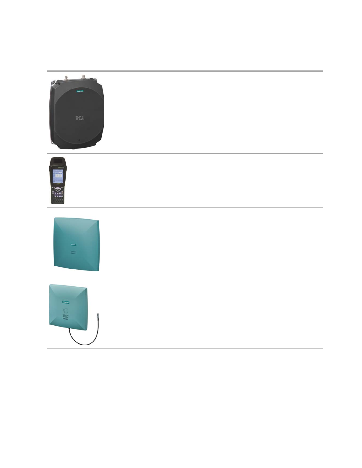
System overview
3.1 RF System SIMATIC RF600
SIMATIC RF600
System Manual, 05/2012, J31069-D0171-U001-A13-7618
27
RF600 products Description
The RF630R reader creates with its connection to a SIMATIC controller optimum
preconditions for production-related application scenarios and/or production-related logistics
applications by RFID. It has 2 connections for external antennas.
SIMATIC RF680M expands the RF600 RF identification system with a powerful mobile
reader for applications in the areas of logistics, production and service. In addition, it is an
indispensable aid for startup and testing.
Also the RF660A antennas are equipped for the harsh conditions in production and logistics
environments due to their high IP67 degree of protection.
Up to 4 antennas can be connected to the RF670R reader depending on the application and
up to two can be connected to the RF630R reader. One antenna can be connected to the
RF640R or RF620R readers as an alternative to the internal antenna.
The SIMATIC RF640A is a circular antenna of medium size for universal applications, for
example material flow and logistics systems.
Depending on the application, up to 4 antennas can be connected to the RF670R reader and
up to two antennas can be connected to the RF630R reader. One antenna can be connected
to the RF640R or RF620R reader as an alternative to the internal antenna.
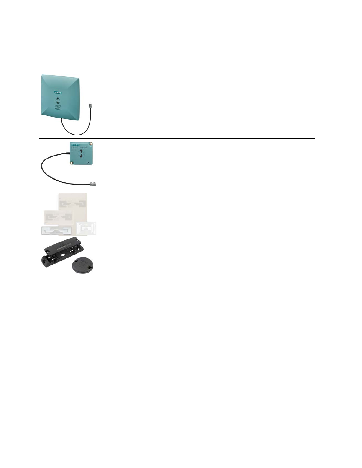
System overview
3.1 RF System SIMATIC RF600
SIMATIC RF600
28 System Manual, 05/2012, J31069-D0171-U001-A13-7618
RF600 products Description
SIMATIC RF642A is a linear antenna of medium size for environments where a lot of metal
occurs.
Depending on the application, up to 4 antennas can be connected to the RF670R reader and
up to two antennas can be connected to the RF630R reader. One antenna can be connected
to the RF640R or RF620R reader as an alternative to the internal antenna.
The SIMATIC RF620A is an antenna of compact, industry-standard design. It is suitable for
UHF transponders with normal (far field) antenna characteristics.
Depending on the application, up to 4 antennas can be connected to the RF670R reader and
up to two antennas can be connected to the RF630R reader. One antenna can be connected
to the RF640R or RF620R reader as an alternative to the internal antenna.
The RF600 tag family offers the right solution for every application:
The RF640T tool tag for industrial requirements is highly resistant to oils and can be directly
mounted on metal.
The RF620T container tag for industrial requirements is rugged and highly resistant to
detergents.
The RF630L Smart Labels made of plastic or paper can be used in many different
applications: The application areas range from simple identification such as electronic
barcode replacement/supplementation, through warehouse and distribution logistics, right up
to product identification
 Loading...