

Siemens SIMATIC RF 300, SIMATIC RF 310-R, SIMATIC RF 320-T, SIMATIC RF 340-T System Manual

simatic sensors
System Manual Edition 05/2005
RFID-SYSTEMS
SIMATIC RF 300


Introduction
1
Safety information
2
System overview
3
RF 300 system planning
4
Readers
5
Transponder/tags
6
Communication modules
7
Accessories
8
Appendix
A
SIMATIC
RFID systems
RF 300
System Manual
Edition 05/2005

Safety Guidelines
This manual contains notices you have to observe in order to ensure your personal safety, as well as to prevent
damage to property. The notices referring to your personal safety are highlighted in the manual by a safety alert
symbol, notices referring to property damage only have no safety alert symbol. These notices shown below are
graded according to the degree of danger.
Danger
indicates that death or severe personal injury will result if proper precautions are not taken.
Warning
indicates that death or severe personal injury may result if proper precautions are not taken.
Caution
with a safety alert symbol, indicates that minor personal injury can result if proper precautions are not taken.
Caution
without a safety alert symbol, indicates that property damage can result if proper precautions are not taken.
Notice
indicates that an unintended result or situation can occur if the corresponding information is not taken into
account.
If more than one degree of danger is present, the warning notice representing the highest degree of danger will
be used. A notice warning of injury to persons with a safety alert symbol may also include a warning relating to
property damage.
Qualified Personnel
The device/system may only be set up and used in conjunction with this documentation. Commissioning and
operation of a device/system may only be performed by qualified personnel. Within the context of the safety notes
in this documentation qualified persons are defined as persons who are authorized to commission, ground and
label devices, systems and circuits in accordance with established safety practices and standards.
Prescribed Usage
Note the following:
Warning
This device may only be used for the applications described in the catalog or the technical description and only in
connection with devices or components from other manufacturers which have been approved or recommended
by Siemens. Correct, reliable operation of the product requires proper transport, storage, positioning and
assembly as well as careful operation and maintenance.
Trademarks
All names identified by ® are registered trademarks of the Siemens AG. The remaining trademarks in this
publication may be trademarks whose use by third parties for their own purposes could violate the rights of the
owner.
Copyright Siemens AG . All rights reserved.
The distribution and duplication of this document or the utiliz ation and transmission of its
contents are not permitted without express written permission. Offenders will be liable for
damages. All rights, including rights created by patent grant or registration of a utility
model or design, are reserved.
Disclaimer of Liability
We have reviewed the contents of this publication to ensure consistency with the
hardware and software described. Since variance cannot be precluded entirely, we cannot
guarantee full consistency. However, the information in this publication is reviewed
regularly and any necessary corrections are included in subsequent editions.
Siemens AG
Automation and Drives
Postfach 4848, 90327 Nuremberg, Germany
Siemens AG 2005
Technical data subject to change
Siemens Aktiengesellschaft --

RF 300
System Manual, 05/2005, (4)J31069 D0166-U001-A1-7618, --
iii
Table of contents
1 Introduction............................................................................................................................................. 1-1
1.1 Navigating in the system manual............................................................................................... 1-2
2 Safety information................................................................................................................................... 2-1
3 System overview..................................................................................................................................... 3-1
3.1 RFID systems............................................................................................................................. 3-1
3.2 RF 300 ....................................................................................................................................... 3-2
3.2.1 RF 300 application areas ........................................................................................................... 3-2
3.2.2 RFID components and their function ......................................................................................... 3-3
3.2.3 Technical data............................................................................................................................ 3-4
4 RF 300 system planning ......................................................................................................................... 4-1
4.1 Fundamentals of application planning .......................................................................................4-1
4.1.1 Transmission window and read/write distance .......................................................................... 4-2
4.1.2 Width of the transmission window.............................................................................................. 4-3
4.1.3 Impact of secondary fields ......................................................................................................... 4-3
4.1.4 Permissible directions of motion of the transponder.................................................................. 4-4
4.1.5 Operation in static and dynamic mode ...................................................................................... 4-5
4.1.6 Dwell time of the transponder .................................................................................................... 4-6
4.1.7 Communication between communication module, reader and transponder ............................. 4-7
4.1.8 Calculation example................................................................................................................... 4-9
4.2 Field data of transponders and readers................................................................................... 4-12
4.3 Impact of the data volume on the transponder speed with RF 310-R (IQ-Sense) .................. 4-13
4.4 Installation guidelines............................................................................................................... 4-14
4.4.1 Overview .................................................................................................................................. 4-14
4.4.2 Reduction of interference due to metal.................................................................................... 4-15
4.4.3 Effects of metal on different transponders and readers........................................................... 4-18
4.4.4 Impact on the transmission window by metal .......................................................................... 4-19
4.5 Chemical resistance of the transponders ................................................................................ 4-21
4.6 EMC Guidelines .............................................
.......................................................................... 4-26
4.6.1 Overview .................................................................................................................................. 4-26
4.6.2 Definition .................................................................................................................................. 4-27
4.6.3 Basic rules................................................................................................................................ 4-28
4.6.4 Propagation of electromagnetic interference ........................................................................... 4-29
4.6.5 Cabinet configuration ............................................................................................................... 4-32
4.6.6 Prevention of interference sources .......................................................................................... 4-35
4.6.7 Equipotential bonding .............................................................................................................. 4-36
4.6.8 Cable shielding......................................................................................................................... 4-37

Table of contents
RF 300
iv System Manual, 05/2005, (4)J31069 D0166-U001-A1-7618, --
5 Readers.................................................................................................................................................. 5-1
5.1 RF 310-R.................................................................................................................................... 5-2
5.1.1 Features ..................................................................................................................................... 5-2
5.1.2 Indicators.................................................................................................................................... 5-2
5.1.3 Transmission window................................................................................................................. 5-3
5.1.4 Metal-free area........................................................................................................................... 5-3
5.1.5 Minimum distance between several RF 310-R units ................................................................. 5-4
5.1.6 RF 310-R field data .................................................................................................................... 5-4
5.1.7 Pin assignment of the IQ-Sense interface .................................................................................5-5
5.1.8 Cable and connector pin assignment......................................................................................... 5-5
5.1.9 Technical data of the RF 310-R ................................................................................................. 5-6
5.1.10 FCC information ......................................................................................................................... 5-7
5.1.11 RF 310-R ordering data ............................................................................................................. 5-7
5.1.12 Dimension drawing..................................................................................................................... 5-8
6 Transponder/tags.................................................................................................................................... 6-1
6.1 RF 320-T .................................................................................................................................... 6-2
6.1.1 Features ..................................................................................................................................... 6-2
6.1.2 Metal-free area........................................................................................................................... 6-3
6.1.3 Field data.................................................................................................................................... 6-4
6.1.4 Technical data............................................................................................................................ 6-5
6.1.5 Ordering data ............................................................................................................................. 6-6
6.1.6 Dimension drawing..................................................................................................................... 6-6
6.2 RF 340-T .................................................................................................................................... 6-7
6.2.1 Features ..................................................................................................................................... 6-7
6.2.2 Metal-free area........................................................................................................................... 6-8
6.2.3 Field data.................................................................................................................................... 6-9
6.2.4 Technical data.......................................................................................................................... 6-10
6.2.5 Ordering data ............................................
............................................................................... 6-11
6.2.6 Dimension drawing................................................................................................................... 6-11
7 Communication modules ........................................................................................................................ 7-1
7.1 8xIQ-Sense ................................................................................................................................ 7-2
7.1.1 Features ..................................................................................................................................... 7-2
7.1.2 Indicators.................................................................................................................................... 7-3
7.1.3 Configuration.............................................................................................................................. 7-4
7.1.4 Addressing ................................................................................................................................. 7-5
7.1.5 Technical data............................................................................................................................ 7-7
7.1.6 Ordering data ............................................................................................................................. 7-7
8 Accessories ............................................................................................................................................ 8-1
8.1 MOBY software .......................................................................................................................... 8-1
A Appendix.................................................................................................................................................A-1
A.1 Certificates and approvals..........................................................................................................A-1
A.2 Service and support ...................................................................................................................A-3
A.3 Contact partners......................................................................................................................... A-3
A.4 Application consulting ................................................................................................................ A-4
A.5 Training ...................................................................................................................................... A-4
List of abbreviations.................................................................................................................... Glossary-1
Glossary ..................................................................................................................................... Glossary-1
Index

Table of contents
RF 300
System Manual, 05/2005, (4)J31069 D0166-U001-A1-7618, --
v
Tables
Table 4-1 Reduction of field data by metal (in %): Transponder and RF 310-R...................................... 4-20
Table 4-2 Interference sources: origin and effect .................................................................................... 4-30
Table 4-3 Causes of coupling paths......................................................................................................... 4-31
Table 5-1 RF 310-R indicators ................................................................................................................... 5-2
Table 5-2 RF 310-R pin assignment .......................................................................................................... 5-5
Table 5-3 Technical data of the RF 310-R ................................................................................................. 5-6
Table 6-1 Field data for transponder RF 320-T to reader RF 310-R ......................................................... 6-4
Table 6-2 Field data for transponder RF 320-T to RF 320-T ..................................................................... 6-4
Table 6-3 Technical data of the RF 320-T ................................................................................................. 6-5
Table 6-4 Field data for transponder RF 340-T to reader RF 310-R ......................................................... 6-9
Table 6-5 Transponder RF 340-T to transponder RF 340-T...................................................................... 6-9
Table 6-6 Technical data of the RF 340-T ............................................................................................... 6-10

Table of contents
RF 300
vi System Manual, 05/2005, (4)J31069 D0166-U001-A1-7618, --

RF 300
System Manual, 05/2005, (4)J31069 D0166-U001-A1-7618, --
1-1
Introduction
1
Purpose of this document
This system manual contains all the information needed to plan and configure the system.
It is intended both for programming and testing/debugging personnel who commission the
system themselves and connect it with other units (automation systems, further
programming devices), as well as for service and maintenance personnel who install
expansions or carry out fault/error analyses.
Scope of validity of this document
This documentation is valid for all supplied variations of the SIMATIC RF 300 system and
describes the state of delivery as of May 2005.
Conventions
The following terms/abbreviations are used synonymously in this document:
• Reader, read/write device, SLG
• Tag, transponder, mobile data memory, MDS
• Communication module, interface module, ASM
History
Previous editions of these operating instructions:
Edition Remarks
05/2005 First Edition
Declaration of conformity
The EC declaration of conformity and the corresponding documentation are made available
to authorities in accordance with the EC directives stated above. Your sales representative
can provide these on request.
Observance of installation guidelines
The installation guidelines and safety instructions given in this documentation must be
followed during commissioning and operation.

Introduction
1.1 Navigating in the system manual
RF 300
1-2 System Manual, 05/2005, (4)J31069 D0166-U001-A1-7618, --
1.1 1.1 Navigating in the system manual
Structure of contents Contents
Contents Organization of the documentation, including the index of pages and chapters
Introduction Purpose, layout and description of the important topics.
Safety information Refers to all the valid technical safety aspects which have to be adhered to while installing,
commissioning and operating the product/system and with reference to statutory
regulations.
System overview Overview of all RF identification systems, system overview of SIMATIC RF 300
RFID system planning Information about possible applications of SIMATIC RF 300, support for application
planning, tools for finding suitable SIMATIC RD 300 components.
Readers Description of readers which can be used for SIMATIC RF 300
Transponders Description of transponders which can be used for SIMATIC RF 300
Communication modules Description of communication modules used for SIMATIC RF 300
Accessories Products available in addition to SIMATIC RF 300
Appendix Service and support, contact partners, training centers
Error messages Overview of error messages
List of abbreviations List of all abbreviations used in the document

RF 300
System Manual, 05/2005, (4)J31069 D0166-U001-A1-7618, --
2-1
Safety information
2
Caution
Please observe the safety instructions on the back cover of this documentation.
SIMATIC RFID products comply with the salient safety specifications to IEC, VDE, EN, UL
and CSA. If you have questions about the admissibility of the installation in the designated
environment, please contact your service representative.
Caution
Alterations to the devices are not permitted.
Failure to observe this requirement shall constitute a revocation of the radio equipment
approval, CE approval and manufacturer's warranty.
Repairs
Repairs may only be carried out by authorized qualified personnel.
Warning
Unauthorized opening of and improper repairs to the device may result in substantial
damage to equipment or risk of personal injury to the user.

Safety information
RF 300
2-2 System Manual, 05/2005, (4)J31069 D0166-U001-A1-7618, --
System expansion
Only install system expansion devices designed for this device. If you install other upgrades,
you may damage the system or violate the safety requirements and regulations for radio
frequency interference suppression. Contact your technical support team or your sales outlet
to find out which system upgrades are suitable for installation.
Caution
If you cause system defects by installing or exchanging system expansion devices, the
warranty becomes void.

RF 300
System Manual, 05/2005, (4)J31069 D0166-U001-A1-7618, --
3-1
System overview
3
3.1 3.1 RFID systems
RFID systems from Siemens control and optimize material flow. They identify reliably,
quickly and economically, are insensitive to contamination and store data directly on the
product.
Identification system Frequency Max. range Max.
memory
Data
transfer rate
(typical) in
byte/s
Max.
temperature
Special features
RF 300 13.56 MHz 0.25 m 20 byte
EEPROM
64 KB
FRAM
3750 SLG: -25 °C
to +70 °C
MDS: -40 °C
to +85 °C
or
+ 220 °C
cyclic
IQ-Sense interface
available;
Battery-free data
memory
MOBY F 125 kHz 0.4 m 192 byte
EEPROM
100 +130 °C Multitag capability
MOBY D 13.56 MHz 0.8 m 112 byte
EEPROM
110 + 85 °C or
+ 200 °C
SmartLabels based
on ISO 15693
e.g. Tagit/Icode
MOBY E 13.56 MHz 0.1 m 752 byte
EEPROM
350 + 150 °C Battery-free data
memory
MOBY I 1.81 MHz 0.15 m 32 KB
FRAM
1250 + 85 °C or
+ 220 °C
cyclic
Battery-free data
memory
MOBY U 2.45 GHz 3.0 m 32 KB RAM 4800 + 85 °C or
+ 220 °C
cyclic
Frequency hopping

System overview
3.2 RF 300
RF 300
3-2 System Manual, 05/2005, (4)J31069 D0166-U001-A1-7618, --
3.2 3.2 RF 300
SIMATIC RF 300 is an inductive identification system specially designed for use in industrial
production for the control and optimization of material flow. Thanks to its compact
components it is particularly suited to small assembly lines and conveyor systems with
restricted space for installation. The rugged components feature an attractive
price/performance ratio.
3.2.1 RF 300 application areas
SIMATIC RF 300 is used primarily for contactless identification of containers, pallets and
workpiece carriers in a closed production loop, i.e. the data carriers (transponders) remain in
the production chain and are not shipped out with the products. Thanks to the compact
enclosure dimensions of both the transponders and readers, SIMATIC RF 300 is particularly
suitable for (small) assembly lines where space is at a premium.
The main application areas of SIMATIC RF 300 are:
• Assembly and handling systems, assembly lines (identification of workpiece carriers)
• Production logistics (material flow control, identification of containers and other vessels)
• Parts identification (e.g. transponder is attached to product/pallet).
• Conveyor systems
System overview
3.2 RF 300
RF 300
System Manual, 05/2005, (4)J31069 D0166-U001-A1-7618, --
3-3
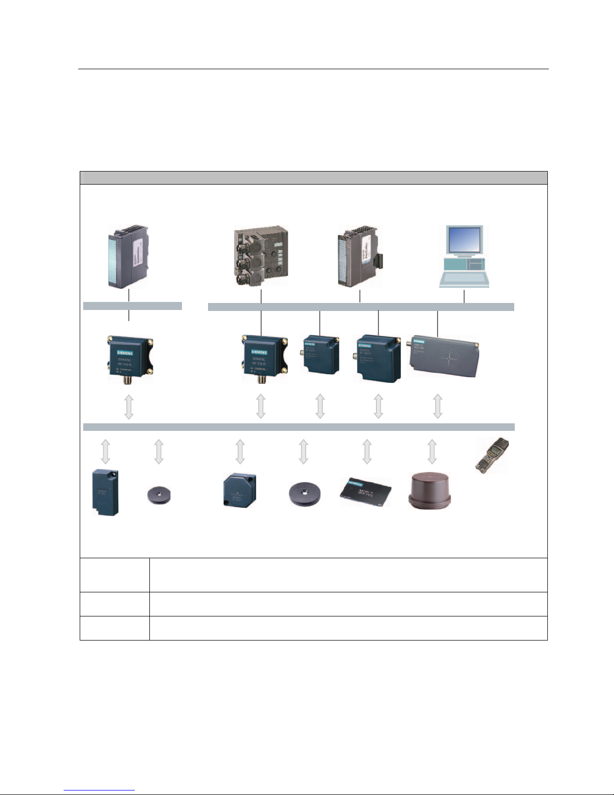
3.2.2 RFID components and their function
RF 300 system components
6HULDODV\QFKURQRXVLQWHUIDFH5656
5)7
5)7
3RZHUDQGGDWDWUDQVPLVVLRQ0+]
5)5
,46HQVHLQWHUIDFH
+DQG
WHUPLQDO
[,46HQVHIRU(70
RQ6ZLWK)&
3&LQWHUIDFHWKLUGSDUW\3/&
$60IRU
6,0$7,&6
$60IRU
352),%86'39
5)7
5)7
5)7
5)7
5)5
5)5
5)5
5)5
Communication
modules
A communication module (interface module) is used to integrate the RF identification system in
PLC/automation systems. In the case of SIMATIC RF 300, the reader is connected to an S7 automation
system either via the 8xIQ-Sense module or an equivalent MOBY interface module (e.g. ASM 475).
Readers The reader ensures inductive communication, supplies power to the transponders, and handles the
connection to the various PLCs (e.g. SIMATIC S7).
Transponders Transponders (mobile data memories) are used, for example, in place of barcodes and can contain all
product-specific data in addition to the product number.
 Loading...