

Siemens SIMATIC RF200 System Manual

SIMATIC Ident
RFID systems
SIMATIC RF200
System Manual
07/2017
J31069
-D0227-U001-A9-7619
Introduction
1
Safety notes
2
System overview
3
Planning the RF200 system
4
Readers
5
Antennas
6
Transponder
7
System integration
8
System diagnostics
9
Appendix
A
Siemens AG
Division Process Industries a
nd Drives
Postfach 48 48
90026 NÜRNBERG
GERMANY
Ⓟ
07/2017 Subject to change
Copyright © Siemens AG 2010 - 2017.
All rights reserved
Legal information
Warning notice system
This manual contains notices you have to observe in order to ensure your personal safety, as well as to prevent
damage to property. The notices referring to your personal safety are highlighted in the manual by a safety alert
symbol, notices referring only to property damage have no safety alert symbol. These notices shown below are
graded according to the degree of danger.
DANGER
indicates that death or severe personal injury will result if proper precautions are not taken.
WARNING
indicates that death or severe personal injury
may
result if proper precautions are not taken.
CAUTION
indicates that minor personal injury can result if proper precautions are not taken.
NOTICE
indicates that property damage can result if proper precautions are not taken.
If more than one degree of danger is present, the warning notice representing the highest degree of danger will
be used. A notice warning of injury to persons with a safety alert symbol may also include a warning relating to
property damage.
Qualified Personnel
The product/system described in this documentation may be operated only by
personnel qualified
for the specific
task in accordance with the relevant documentation, in particular its warning notices and safety instructions.
Qualified personnel are those who, based on their training and experience, are capable of identifying risks and
avoiding potential hazards when working with these products/systems.
Proper use of Siemens products
Note the following:
WARNING
Siemens products may only be used for the applications described in the catalog and in the relevant technical
documentation. If products and components from other manufacturers are used, these must be recommended
or approved by Siemens. Proper transport, storage, installation, assembly, commissioning, operation and
maintenance are required to ensure that the products operate safely and without any problems. The permissible
ambient conditions must be complied with. The information in the relevant documentation must be observed.
Trademarks
All names identified by ® are registered trademarks of Siemens AG. The remaining trademarks in this publication
may be trademarks whose use by third parties for their own purposes could violate the rights of the owner.
Disclaimer of Liability
We have reviewed the contents of this publication to ensure consistency with the hardware and software
described. Since variance cannot be precluded entirely, we cannot guarantee full consistency. However, the
information in this publication is reviewed regularly and any necessary corrections are included in subsequent
editions.

SIMATIC RF200
System Manual, 07/2017, J31069-D0227-U001-A9-7619
3
Table of contents
1 Introduction ........................................................................................................................................... 13
1.1 Abbreviations and naming conventions .................................................................................. 14
2 Safety notes .......................................................................................................................................... 15
3 System overview ................................................................................................................................... 19
3.1 RFID components and their function ...................................................................................... 20
3.2 Overview of transponders ....................................................................................................... 23
4 Planning the RF200 system .................................................................................................................. 27
4.1 Fundamentals of application planning .................................................................................... 27
4.1.1 Selection criteria for SIMATIC RF200 components ................................................................ 27
4.1.2 Transmission window and read/write distance ....................................................................... 27
4.1.3 Width of the transmission window .......................................................................................... 30
4.1.4 Impact of secondary fields ...................................................................................................... 31
4.1.5 Permissible directions of motion of the transponder ............................................................... 34
4.1.6 Operation in static and dynamic mode ................................................................................... 35
4.1.7 Dwell time of the transponder ................................................................................................. 36
4.1.8 Communication between communication module, reader and transponder .......................... 37
4.2 Field data of transponders and readers .................................................................................. 38
4.2.1 Field data ................................................................................................................................ 39
4.2.2 Minimum clearances ............................................................................................................... 48
4.3 Installation guidelines.............................................................................................................. 50
4.3.1 Overview ................................................................................................................................. 50
4.3.2 Reduction of interference due to metal ................................................................................... 51
4.3.3 Effects of metal on different transponders and readers .......................................................... 53
4.3.4 Impact of metal on the transmission window .......................................................................... 54
4.3.4.1 RF210R ................................................................................................................................... 55
4.3.4.2 RF220R ................................................................................................................................... 58
4.3.4.3 RF240R ................................................................................................................................... 60
4.3.4.4 RF250R ................................................................................................................................... 63
4.3.4.5 RF260R ................................................................................................................................... 71
4.3.4.6 RF280R ................................................................................................................................... 74
4.3.4.7 RF290R ................................................................................................................................... 76
4.3.5 Installation and connection of 2 to 6 antennas with one RF290R reader ............................... 80
4.3.5.1 Installation options with the antenna splitter (2-4 antennas) .................................................. 80
4.3.5.2 Antenna installation ................................................................................................................. 84
4.3.5.3 Installation options with the antenna multiplexer (2-6 antennas) ........................................... 88
4.3.6 Chemical resistance of the reader and transponders ............................................................. 89
4.3.6.1 Readers .................................................................................................................................. 89
4.3.6.2 Transponder ............................................................................................................................ 93
4.4 Further information ................................................................................................................ 101

Table of contents
SIMATIC RF200
4 System Manual, 07/2017, J31069-D0227-U001-A9-7619
5 Readers ............................................................................................................................................... 103
5.1 SIMATIC RF210R ................................................................................................................ 104
5.1.1 Features ............................................................................................................................... 104
5.1.2 RF210R ordering data ......................................................................................................... 104
5.1.3 Pin assignment RF210R with RS422 interface .................................................................... 105
5.1.4 LED operating display .......................................................................................................... 105
5.1.5 Minimum distance between RF210R readers ...................................................................... 106
5.1.6 Technical specifications of the RF210R reader ................................................................... 107
5.1.7 Approvals ............................................................................................................................. 108
5.1.8 Dimension drawing .............................................................................................................. 109
5.2 SIMATIC RF210M ................................................................................................................ 110
5.2.1 Features ............................................................................................................................... 110
5.2.2 Ordering data RF210M ........................................................................................................ 110
5.2.3 Installing the RF210M reader ............................................................................................... 111
5.2.4 Pin assignment RF210M with RS-422 interface .................................................................. 112
5.2.5 LED operating display .......................................................................................................... 112
5.2.6 Technical specifications of the RF210M reader ................................................................... 113
5.2.7 Approvals ............................................................................................................................. 114
5.2.8 Dimension drawing ..............................................................................................................
115
5.3 SIMATIC RF220R ................................................................................................................ 116
5.3.1 Features ............................................................................................................................... 116
5.3.2 RF220R ordering data ......................................................................................................... 116
5.3.3 RF220R pin assignment with RS422 interface .................................................................... 117
5.3.4 LED operating display .......................................................................................................... 117
5.3.5 Minimum distance between RF220R readers ...................................................................... 118
5.3.6 Technical specifications of the RF220R reader ................................................................... 119
5.3.7 Approvals ............................................................................................................................. 120
5.3.8 Dimension drawing .............................................................................................................. 121
5.4 SIMATIC RF240R ................................................................................................................ 122
5.4.1 Features ............................................................................................................................... 122
5.4.2 RF240R ordering data ......................................................................................................... 122
5.4.3 Pin assignment RF240R ...................................................................................................... 123
5.4.4 LED operating display .......................................................................................................... 123
5.4.5 Minimum distance between several RF240R readers ......................................................... 124
5.4.6 Technical specifications of the RF240R reader ................................................................... 125
5.4.7 Approvals ............................................................................................................................. 127
5.4.8 Dimension drawing
.............................................................................................................. 128
5.5 SIMATIC RF250R ................................................................................................................ 128
5.5.1 Features ............................................................................................................................... 128
5.5.2 Ordering data RF250R ......................................................................................................... 129
5.5.3 Pin assignment RF250R ...................................................................................................... 129
5.5.4 LED operating display .......................................................................................................... 129
5.5.5 Technical specifications of the RF250R reader ................................................................... 130
5.5.6 Approvals ............................................................................................................................. 131
5.5.7 Dimension drawing .............................................................................................................. 133
5.6 SIMATIC RF260R ................................................................................................................ 134
5.6.1 Features ............................................................................................................................... 134
5.6.2 Ordering data for RF260R ................................................................................................... 134
5.6.3 Pin assignment RF260R ...................................................................................................... 135

Table of contents
SIMATIC RF200
System Manual, 07/2017, J31069-D0227-U001-A9-7619
5
5.6.4 LED operating display ........................................................................................................... 135
5.6.5 Minimum distance between several RF260R ....................................................................... 136
5.6.6 Technical data of the RF260R reader................................................................................... 137
5.6.7 Approvals .............................................................................................................................. 138
5.6.8 Dimension drawing ............................................................................................................... 139
5.7 SIMATIC RF280R ................................................................................................................. 140
5.7.1 Features ................................................................................................................................ 140
5.7.2 Ordering data RF280R.......................................................................................................... 140
5.7.3 Pin assignment RF280R ....................................................................................................... 141
5.7.4 LED operating display ........................................................................................................... 141
5.7.5 Minimum distance between RF280R readers ...................................................................... 142
5.7.6 Technical specifications of the RF280R reader .................................................................... 143
5.7.7 Approvals .............................................................................................................................. 144
5.7.8 Dimension drawing ............................................................................................................... 146
5.8 SIMATIC RF290R ................................................................................................................. 147
5.8.1 Features ................................................................................................................................ 147
5.8.2 Ordering data RF290R.......................................................................................................... 147
5.8.3 Pin assignment RF290R ....................................................................................................... 149
5.8.4 LED operating display ........................................................................................................... 151
5.8.5 Installing the RF290R reader ................................................................................................ 152
5.8.5.1 Wall mounting ....................................................................................................................... 152
5.8.5.2 Installing on the S7-300 standard rail ................................................................................... 153
5.8.5.3 Installation on a DIN rail ........................................................................................................ 153
5.8.6 Technical specifications of the RF290R reader .................................................................... 155
5.8.7 Approvals .............................................................................................................................. 156
5.8.8 Note on the use of the RF290R as a replacement for SLG D10 / SLG D10S ...................... 158
5.8.9 Dimension drawing ............................................................................................................... 159
6 Antennas ............................................................................................................................................ 161
6.1 ANT 1 .................................................................................................................................... 161
6.1.1 Characteristics ...................................................................................................................... 161
6.1.2 Ordering data ........................................................................................................................ 161
6.1.3 Flush-mounted in metal ........................................................................................................ 162
6.1.4 Operating / limit distances .................................................................................................... 162
6.1.5 Minimum clearances ............................................................................................................. 163
6.1.6 Technical specifications ........................................................................................................ 164
6.1.7 Dimension drawing ............................................................................................................... 165
6.2 ANT 3 .................................................................................................................................... 166
6.2.1 Features ................................................................................................................................ 166
6.2.2 Ordering data ........................................................................................................................ 166
6.2.3 Mounting on/in metal............................................................................................................. 167
6.2.4 Operating / limit distances .................................................................................................... 168
6.2.5 Minimum spacing .................................................................................................................. 169
6.2.6 Technical data ....................................................................................................................... 170
6.2.7 Dimension drawing ............................................................................................................... 171
6.3 ANT 8 .................................................................................................................................... 172
6.3.1
Features ................................................................................................................................ 172
6.3.2 Ordering data ........................................................................................................................ 172
6.3.3 Transmission window............................................................................................................ 173
6.3.4 Flush-mounted in metal ........................................................................................................ 173

Table of contents
SIMATIC RF200
6 System Manual, 07/2017, J31069-D0227-U001-A9-7619
6.3.5 Minimum spacing ................................................................................................................. 174
6.3.6 Technical data ...................................................................................................................... 175
6.3.7 Dimension drawing .............................................................................................................. 176
6.4 ANT 12 ................................................................................................................................. 177
6.4.1 Features ............................................................................................................................... 177
6.4.2 Ordering data ....................................................................................................................... 177
6.4.3 Transmission window ........................................................................................................... 178
6.4.4 Flush-mounted in metal ....................................................................................................... 178
6.4.5 Minimum spacing ................................................................................................................. 179
6.4.6 Technical data ...................................................................................................................... 180
6.4.7 Dimension drawing .............................................................................................................. 181
6.5 ANT 18 ................................................................................................................................. 182
6.5.1 Features ............................................................................................................................... 182
6.5.2 Ordering data ....................................................................................................................... 182
6.5.3 Transmission window ........................................................................................................... 183
6.5.4 Flush-mounted in metal ....................................................................................................... 183
6.5.5
Minimum spacing ................................................................................................................. 184
6.5.6 Technical data ...................................................................................................................... 185
6.5.7 Dimension drawing .............................................................................................................. 186
6.6 ANT 30 ................................................................................................................................. 187
6.6.1 Features ............................................................................................................................... 187
6.6.2 Ordering data ....................................................................................................................... 187
6.6.3 Transmission window ........................................................................................................... 188
6.6.4 Flush-mounted in metal ....................................................................................................... 189
6.6.5 Minimum spacing ................................................................................................................. 189
6.6.6 Technical data ...................................................................................................................... 190
6.6.7 Dimension drawing .............................................................................................................. 191
6.7 ANT D5 ................................................................................................................................ 192
6.7.1 Features ............................................................................................................................... 192
6.7.2 Ordering data ....................................................................................................................... 192
6.7.3 Transmission window ........................................................................................................... 193
6.7.4 Flush-mounted in metal ....................................................................................................... 194
6.7.5 Minimum spacing ................................................................................................................. 194
6.7.6 Technical data ......................................................................................................................
195
6.7.7 Dimension drawing .............................................................................................................. 197
6.8 ANT D6 ................................................................................................................................ 198
6.8.1 Features ............................................................................................................................... 198
6.8.2 Ordering data ....................................................................................................................... 198
6.8.3 Transmission window ........................................................................................................... 199
6.8.4 Metal-free area ..................................................................................................................... 200
6.8.5 Minimum spacing ................................................................................................................. 200
6.8.6 Technical data ...................................................................................................................... 201
6.8.7 Dimensional diagram ........................................................................................................... 202
6.9 ANT D10 .............................................................................................................................. 203
6.9.1 Features ............................................................................................................................... 203
6.9.2 Ordering data ....................................................................................................................... 203
6.9.3 Transmission window ........................................................................................................... 204
6.9.4 Metal-free area ..................................................................................................................... 205
6.9.5 Minimum spacing ................................................................................................................. 206

Table of contents
SIMATIC RF200
System Manual, 07/2017, J31069-D0227-U001-A9-7619
7
6.9.6 Technical data ....................................................................................................................... 206
6.9.7 Dimensional diagram ............................................................................................................ 208
7 Transponder ....................................................................................................................................... 209
7.1 Memory configuration of ISO the transponders .................................................................... 209
7.2 MDS D100 ............................................................................................................................ 210
7.2.1 Characteristics ...................................................................................................................... 210
7.2.2 Ordering data ........................................................................................................................ 210
7.2.3 Metal-free area ...................................................................................................................... 211
7.2.4 Technical data ....................................................................................................................... 212
7.2.5 Dimension drawing ............................................................................................................... 214
7.3 MDS D117 ............................................................................................................................ 215
7.3.1 Features ................................................................................................................................ 215
7.3.2 Ordering data ........................................................................................................................ 215
7.3.3 Mounting in metal .................................................................................................................. 215
7.3.4 Technical specifications ........................................................................................................ 216
7.3.5 Dimension drawing ............................................................................................................... 217
7.4 MDS D124 ............................................................................................................................ 218
7.4.1 Characteristics ...................................................................................................................... 218
7.4.2 Ordering data ........................................................................................................................ 218
7.4.3 Mounting on metal ................................................................................................................ 219
7.4.4
Technical specifications ........................................................................................................ 220
7.4.5 Use of the MDS D124 in hazardous area ............................................................................. 221
7.4.6 Dimension drawing ............................................................................................................... 223
7.5 MDS D126 ............................................................................................................................ 224
7.5.1 Characteristics ...................................................................................................................... 224
7.5.2 Ordering data ........................................................................................................................ 224
7.5.3 Mounting on metal ................................................................................................................ 225
7.5.4 Technical specifications ........................................................................................................ 226
7.5.5 Dimension drawing ............................................................................................................... 227
7.6 MDS D127 ............................................................................................................................ 228
7.6.1 Features ................................................................................................................................ 228
7.6.2 Ordering data ........................................................................................................................ 228
7.6.3 Mounting in metal .................................................................................................................. 229
7.6.4 Technical specifications ........................................................................................................ 230
7.6.5 Dimension drawing ............................................................................................................... 231
7.7 MDS D139 ............................................................................................................................ 232
7.7.1 Characteristics ...................................................................................................................... 232
7.7.2 Ordering data ........................................................................................................................
232
7.7.3 Metal-free area ...................................................................................................................... 233
7.7.4 Mounting in metal .................................................................................................................. 234
7.7.5 Cleaning the transponder ..................................................................................................... 234
7.7.6 Technical specifications ........................................................................................................ 235
7.7.7 Use of the MDS D139 in hazardous areas ........................................................................... 236
7.7.8 Dimension drawings .............................................................................................................. 238
7.8 MDS D160 ............................................................................................................................ 239
7.8.1 Characteristics ...................................................................................................................... 239
7.8.2 Ordering data ........................................................................................................................ 239
7.8.3 Mounting on metal ................................................................................................................ 240

Table of contents
SIMATIC RF200
8 System Manual, 07/2017, J31069-D0227-U001-A9-7619
7.8.4 Technical specifications ....................................................................................................... 240
7.8.5 Dimension drawings ............................................................................................................. 242
7.9 MDS D165 ............................................................................................................................ 243
7.9.1 Features ............................................................................................................................... 243
7.9.2 Ordering data ....................................................................................................................... 243
7.9.3 Technical data ...................................................................................................................... 244
7.9.4 Dimension drawing .............................................................................................................. 245
7.10 MDS D200 ............................................................................................................................ 246
7.10.1 Features ............................................................................................................................... 246
7.10.2 Ordering data ....................................................................................................................... 246
7.10.3 Mounting on metal ............................................................................................................... 247
7.10.4 Technical data ...................................................................................................................... 248
7.10.5 Dimension drawing .............................................................................................................. 250
7.11 MDS D261 ............................................................................................................................ 250
7.11.1 Features ............................................................................................................................... 250
7.11.2 Ordering data ....................................................................................................................... 250
7.11.3 Technical data ......................................................................................................................
251
7.11.4 Dimension drawing .............................................................................................................. 252
7.12 MDS D324 ............................................................................................................................ 253
7.12.1 Characteristics ..................................................................................................................... 253
7.12.2 Ordering data ....................................................................................................................... 253
7.12.3 Mounting on metal ............................................................................................................... 254
7.12.4 Technical specifications ....................................................................................................... 255
7.12.5 Dimension drawing .............................................................................................................. 256
7.13 MDS D339 ............................................................................................................................ 257
7.13.1 Characteristics ..................................................................................................................... 257
7.13.2 Ordering data ....................................................................................................................... 257
7.13.3 Mounting on metal ............................................................................................................... 258
7.13.4 Mounting in metal ................................................................................................................. 259
7.13.5 Cleaning the transponder ..................................................................................................... 259
7.13.6 Technical specifications ....................................................................................................... 260
7.13.7 Use of the MDS D339 in hazardous areas .......................................................................... 261
7.13.8 Dimensional drawing ............................................................................................................ 263
7.14 MDS D400 ............................................................................................................................ 264
7.14.1
Features ............................................................................................................................... 264
7.14.2 Ordering data ....................................................................................................................... 264
7.14.3 Mounting on metal ............................................................................................................... 265
7.14.4 Technical specifications ....................................................................................................... 266
7.14.5 Dimension drawing .............................................................................................................. 268
7.15 MDS D421 ............................................................................................................................ 269
7.15.1 Characteristics ..................................................................................................................... 269
7.15.2 Ordering data ....................................................................................................................... 269
7.15.3 Mounting on metal ............................................................................................................... 270
7.15.4 Technical specifications ....................................................................................................... 272
7.15.5 Dimension drawing .............................................................................................................. 273
7.16 MDS D422 ............................................................................................................................ 274
7.16.1 Characteristics ..................................................................................................................... 274
7.16.2 Ordering data ....................................................................................................................... 274

Table of contents
SIMATIC RF200
System Manual, 07/2017, J31069-D0227-U001-A9-7619
9
7.16.3 Mounting in metal .................................................................................................................. 274
7.16.4 Technical specifications ........................................................................................................ 275
7.16.5 Dimension drawing ............................................................................................................... 276
7.17 MDS D423 ............................................................................................................................ 277
7.17.1 Characteristics ...................................................................................................................... 277
7.17.2 Ordering data ........................................................................................................................ 277
7.17.3 Mounting on metal ................................................................................................................ 277
7.17.4 Technical specifications ........................................................................................................ 279
7.17.5 Dimensional drawing............................................................................................................. 281
7.18 MDS D424 ............................................................................................................................ 281
7.18.1 Characteristics ...................................................................................................................... 281
7.18.2 Ordering data ........................................................................................................................ 282
7.18.3 Mounting on metal ................................................................................................................ 282
7.18.4 Technical specifications ........................................................................................................ 283
7.18.5 Dimension drawing ............................................................................................................... 285
7.19 MDS D425 ............................................................................................................................ 285
7.19.1 Characteristics ......................................................................................................................
285
7.19.2 Ordering data ........................................................................................................................ 286
7.19.3 Application example .............................................................................................................. 286
7.19.4 Technical specifications ........................................................................................................ 286
7.19.5 Dimension drawing ............................................................................................................... 288
7.20 MDS D426 ............................................................................................................................ 288
7.20.1 Characteristics ...................................................................................................................... 288
7.20.2 Mounting on metal ................................................................................................................ 289
7.20.3 Ordering data ........................................................................................................................ 290
7.20.4 Technical specifications ........................................................................................................ 290
7.20.5 Dimension drawing ............................................................................................................... 291
7.21 MDS D428 ............................................................................................................................ 292
7.21.1 Characteristics ...................................................................................................................... 292
7.21.2 Ordering data ........................................................................................................................ 292
7.21.3 Application example .............................................................................................................. 293
7.21.4 Technical specifications ........................................................................................................ 293
7.21.5 Dimension drawing ............................................................................................................... 295
7.22 MDS D460 ............................................................................................................................ 295
7.22.1
Characteristics ...................................................................................................................... 295
7.22.2 Ordering data ........................................................................................................................ 296
7.22.3 Mounting on metal ................................................................................................................ 296
7.22.4 Technical specifications ........................................................................................................ 297
7.22.5 Dimension drawings .............................................................................................................. 298
7.23 MDS D521 ............................................................................................................................ 299
7.23.1 Characteristics ...................................................................................................................... 299
7.23.2 Ordering data ........................................................................................................................ 299
7.23.3 Mounting on metal ................................................................................................................ 299
7.23.4 Technical specifications ........................................................................................................ 301
7.23.5 Dimension drawing ............................................................................................................... 303
7.24 MDS D522 ............................................................................................................................ 303
7.24.1 Characteristics ...................................................................................................................... 303
7.24.2 Ordering data ........................................................................................................................ 304

Table of contents
SIMATIC RF200
10 System Manual, 07/2017, J31069-D0227-U001-A9-7619
7.24.3 Mounting in metal ................................................................................................................. 304
7.24.4 Technical specifications ....................................................................................................... 305
7.24.5 Dimension drawing .............................................................................................................. 306
7.25 MDS D522 special variant ................................................................................................... 307
7.25.1 Characteristics ..................................................................................................................... 307
7.25.2 Ordering data ....................................................................................................................... 307
7.25.3 Mounting in metal ................................................................................................................. 308
7.25.4 Installation instructions ......................................................................................................... 308
7.25.5 Technical specifications ....................................................................................................... 310
7.25.6 Dimensional drawing ............................................................................................................ 311
7.26 MDS D524 ............................................................................................................................ 312
7.26.1 Characteristics ..................................................................................................................... 312
7.26.2 Ordering data ....................................................................................................................... 312
7.26.3 Mounting on metal ............................................................................................................... 313
7.26.4 Technical specifications ....................................................................................................... 314
7.26.5 Dimension drawing .............................................................................................................. 315
7.27 MDS D526
............................................................................................................................ 316
7.27.1 Characteristics ..................................................................................................................... 316
7.27.2 Ordering data ....................................................................................................................... 316
7.27.3 Mounting on metal ............................................................................................................... 317
7.27.4 Technical specifications ....................................................................................................... 318
7.27.5 Dimension drawing .............................................................................................................. 319
7.28 MDS D528 ............................................................................................................................ 320
7.28.1 Characteristics ..................................................................................................................... 320
7.28.2 Ordering data ....................................................................................................................... 320
7.28.3 Application example ............................................................................................................. 321
7.28.4 Technical specifications ....................................................................................................... 321
7.28.5 Dimension drawing .............................................................................................................. 323
8 System integration ............................................................................................................................... 325
9 System diagnostics .............................................................................................................................. 329
9.1 Error codes of the RF200 readers ....................................................................................... 329
9.2 Diagnostics functions - STEP 7 ........................................................................................... 331
9.2.1 Reader diagnostics with "Reader Status" (SLG Status) ...................................................... 331
9.2.2 Transponder diagnostics with "Tag Status" (MDS Status) .................................................. 333
A Appendix ............................................................................................................................................. 335
A.1 Certificates & approvals ....................................................................................................... 335
A.2 Accessories .......................................................................................................................... 337
A.2.1 Antenna splitter .................................................................................................................... 337
A.2.2 Antenna multiplexer SIMATIC RF260X ............................................................................... 339
A.2.2.1 Characteristics ..................................................................................................................... 339
A.2.2.2 Ordering data ....................................................................................................................... 339
A.2.2.3 Description ........................................................................................................................... 340
A.2.2.4 Principle of operation ........................................................................................................... 340
A.2.2.5 Connectors ........................................................................................................................... 341
A.2.2.6 Configuration ........................................................................................................................ 342
A.2.2.7 Parameterization .................................................................................................................. 342
A.2.2.8 RF260X commands ............................................................................................................. 344

Table of contents
SIMATIC RF200
System Manual, 07/2017, J31069-D0227-U001-A9-7619
11
A.2.2.9 Technical specifications ........................................................................................................ 345
A.2.2.10 Dimensional drawing............................................................................................................. 346
A.2.3 Wide-range power supply unit for SIMATIC RF systems ..................................................... 347
A.2.3.1 Features ................................................................................................................................ 347
A.2.3.2 Scope of supply .................................................................................................................... 348
A.2.3.3 Ordering data ........................................................................................................................ 348
A.2.3.4 Safety Information ................................................................................................................. 348
A.2.3.5 Connecting ............................................................................................................................ 349
A.2.3.6 Technical specifications ........................................................................................................ 350
A.2.3.7 Pin assignment of DC outputs and mains connection .......................................................... 352
A.2.3.8 Dimension drawing ............................................................................................................... 353
A.2.3.9 Certificates and approvals .................................................................................................... 354
A.2.4 Transponder holders ............................................................................................................. 355
A.3 Connecting cable .................................................................................................................. 361
A.3.1 Reader RF2xxR (RS-422) with ASM 456 / RF160C / RF170C / RF180C / RF182C ........... 361
A.3.2 Reader RF2xxR (RS-422) with ASM 475 ............................................................................. 363
A.3.3 Reader RF2xxR (RS-422) with RF120C...............................................................................
364
A.3.4 Reader RF240R/RF260R/RF290R (RS232) with PC ........................................................... 364
A.3.5 Reader RF290R .................................................................................................................... 366
A.4 Ordering data ........................................................................................................................ 367
A.5 Service & Support ................................................................................................................. 377
Index................................................................................................................................................... 379

Table of contents
SIMATIC RF200
12 System Manual, 07/2017, J31069-D0227-U001-A9-7619

SIMATIC RF200
System Manual, 07/2017, J31069-D0227-U001-A9-7619
13
1
Introduction
SIMATIC RF200 is a compact RFID system in the SIMATIC RFID product family. The
product range comprises cost-efficient RF readers that are ideal for use in small assembly
lines or in intralogistics. SIMATIC RF200 RFID readers only support the RFID standard ISO
15693 and are therefore ideal for operation with the extensive range of ISO 15693
transponders.
The readers of the RF200 product family are available with the following interfaces:
● RS-422 for connecting to the communications modules
● RS-232 with a simple ASCII protocol for connection to PCs and third-party controllers
● IO-Link for connection to IO Link masters from Siemens and third-party controllers
Readers with an internal antenna have a particularly compact design
(RF210R/RF220R/RF240R/RF260R). RF250R and RF290R are designed for operation with
external antennas either to achieve longer distances or larger field sizes (RF290R with ANT
D5/D6/D10) or to allow installation where there is very little space (RF250R with ANT
3/8/12/18/30).
Scope of validity of this document
This documentation is valid for all variants of the SIMATIC RF200 system and describes the
devices shipped as of July 2015.
Registered trademarks
SIMATIC ®, SIMATIC RF ®, MOBY ®, RF MANAGER ® and SIMATIC Sensors ® are registered
trademarks of Siemens AG.
Further information
For additional information, refer to the manuals:
● Function manual "Ident profile and Ident blocks"
(https://support.industry.siemens.com/cs/us/en/view/106368029
)
● Function manual "FB 45" (https://support.industry.siemens.com/cs/ww/en/view/21738808)
● Operating instructions "RF200 IO-Link"
(https://support.industry.siemens.com/cs/ww/en/view/60641859
)
● System manual "MOBY D"
(https://support.industry.siemens.com/cs/ww/en/view/13628689
)

Introduction
1.1 Abbreviations and naming conventions
SIMATIC RF200
14 System Manual, 07/2017, J31069-D0227-U001-A9-7619
● Operating instructions "RF310M"
(https://support.industry.siemens.com/cs/us/en/view/51812642
)
● Product information "RF200 command set"
(https://support.industry.siemens.com/cs/us/en/view/44864850
)
History
The following issues of the SIMATIC RF200 system manual have been published:
Output
Note
03/2011
First edition
05/2011 Expansion of the documentation with the addition of the device variant RF260R with
RS-232 interface
09/2011
Expansion of the documentation with the device variant RF240R
03/2013 Expansion of the documentation with the device variant RF290R
09/2013 Expansion of the documentation by the following:
• The device variant RF250R
• The device variants RF240R and RF260R with ASCII interface
• Antennas ANT 8, ANT 12, ANT 18 and ANT 30
• Transponder
07/2015 Expansion of the documentation by the following:
• ANT 3 antennas
• MDS D5xx transponder
• Mobile reader RF210R
05/2017 Expansion of the documentation by the following:
• Device version RF280R
• Mobile Reader RF350M
1.1
Abbreviations and naming conventions
Abbreviations and naming conventions
The following terms/abbreviations are used synonymously in this document:
Reader
Write/read device (SLG)
Transponder, tag
Data carrier, mobile data storage, (MDS)
Communications module (CM)
Interface module (ASM)
SIMATIC RF200
System Manual, 07/2017, J31069-D0227-U001-A9-7619
15
2
SIMATIC RFID products comply with the salient safety specifications acc. to IEC, VDE, EN,
UL and CSA. If you have questions about the permissibility of the installation in the planned
environment, please contact your service representative.
WARNING
Opening the device
Do not open the device when when the power supply is on. Unauthorized opening of and
improper repairs to the device may result in substantial damage to equipment or risk of
personal injury to the user.
NOTICE
Alterations not permitted
Alterations to the devices are not permitted.
Failure to observe this requirement shall constitute a revocation of the radio equipment
approval, CE approval and manufacturer's warranty.
Installation instructions
NOTICE
Switch/fuse to disconnect the reader from the power supply
Make sure that the readers can be disconnected from the power supply with a switch or a
fuse. The function of the switch or fuse must be clearly recognizable.
Operating temperature
CAUTION
Danger of burns
Note that some outer components of the reader are made of metal. Depending on the
environmental conditions temperatures can occur on the device that are higher than the
maximum permitted operating temperature.
Safety notes
SIMATIC RF200
16 System Manual, 07/2017, J31069-D0227-U001-A9-7619
Repairs
WARNING
Repairs only by authorized qualified personnel
Repairs may only be carried out by authorized qualified personnel. Unauthorized openi
ng of
and improper repairs to the device may result in substantial damage to equipment or risk of
personal injury to the user.
System expansions
Only install system expansions intended for this system. If you install other expansions, you
may damage the system or violate the safety requirements and regulations for radio
frequency interference suppression. Contact Technical Support or your local sales
department to find out which system expansions are suitable for installation.
NOTICE
Warranty conditions
If you cause system defects by installing or exchanging system expansion devices, the
warranty becomes void.
Safety distances
CAUTION
Safety distance between reader/antenna and persons
Note that for permanent exposure, the following safety distances must be adhered to:
• RF310R: ≥ 80 mm
• RF340R: ≥ 130 mm
• RF350R + ANT 1: ≥ 140 mm
• RF350R + ANT 3: ≥ 80 mm
• RF350R + ANT 12: ≥ 25 mm
• RF350R + ANT 18: ≥ 50 mm
• RF350R + ANT 30: ≥ 80 mm
• RF380R: ≥ 250 mm
• RF382R: ≥ 130 mm
Note
Safety distance with pacemakers
A safety distance between reader/antenna and persons with pacemakers is not necessary.

Safety notes
SIMATIC RF200
System Manual, 07/2017, J31069-D0227-U001-A9-7619
17
Security information
Siemens provides products and solutions with industrial security functions that support the
secure operation of plants, systems, machines and networks.
In order to protect plants, systems, machines and networks against cyber threats, it is
necessary to implement – and continuously maintain – a holistic, state-of-the-art industrial
security concept. Siemens’ products and solutions only form one element of such a concept.
Customer is responsible to prevent unauthorized access to its plants, systems, machines
and networks. Systems, machines and components should only be connected to the
enterprise network or the internet if and to the extent necessary and with appropriate security
measures (e.g. use of firewalls and network segmentation) in place.
Additionally, Siemens’ guidance on appropriate security measures should be taken into
account. For more information about industrial security, please visit
Link: (http://www.siemens.com/industrialsecurity
)
Siemens’ products and solutions undergo continuous development to make them more
secure. Siemens strongly recommends to apply product updates as soon as available and to
always use the latest product versions. Use of product versions that are no longer supported,
and failure to apply latest updates may increase customer’s exposure to cyber threats.
To stay informed about product updates, subscribe to the Siemens Industrial Security RSS
Feed under
Link: (http://www.siemens.com/industrialsecurity
).

Safety notes
SIMATIC RF200
18 System Manual, 07/2017, J31069-D0227-U001-A9-7619

SIMATIC RF200
System Manual, 07/2017, J31069-D0227-U001-A9-7619
19
3
SIMATIC RF200 is an inductive identification system that is compatible with the ISO 15693
standard and was specially designed for use in industrial production for the control and
optimization of material flows.
In contrast to SIMATIC RF300, SIMATIC RF200 is intended for RFID applications where
performance requirements are not very high, for example with regard to data volume,
transfer rate or diagnostics options. SIMATIC RF200 is characterized by particularly
favorable prices.

System overview
3.1 RFID components and their function
SIMATIC RF200
20 System Manual, 07/2017, J31069-D0227-U001-A9-7619
3.1
RFID components and their function
RF200 system components
Figure 3-1 RF200 system overview

System overview
3.1 RFID components and their function
SIMATIC RF200
System Manual, 07/2017, J31069-D0227-U001-A9-7619
21
Table 3- 1 Reader-transponder combination options, Part 1
Transponder
RF210R/
RF210M
RF220R
RF240R
RF260R
RF280R
RF290R 4)
RF350M
MDS D100
-- ○ ✓ ✓ ✓ ✓ ✓
MDS D117
○ -- -- -- -- -- ✓
6)
MDS D124
✓ ✓ ✓ ✓ ✓ ✓ ✓
MDS D126
-- ✓ ✓ ✓ ✓ ✓ ✓
MDS D127
✓
--
--
--
--
--
✓
6)
MDS D139 1)
-- ○ ○ ✓ ✓ ✓ ✓
MDS D160 2)
✓ ✓ ✓ ✓ ✓ ✓ ✓
MDS D165
-- ○ ✓ ✓ ✓ ✓ ✓
MDS D200
-- ○ ✓ ✓ ✓ ✓ ✓
MDS D261
-- ○ ✓ ✓ ✓ ✓ ✓
MDS D324
✓ ✓ ✓ ✓ ✓ ✓ ✓
MDS D339
-- ○ ○ ✓ ✓ ✓ ✓
MDS D400
--
-- ✓ ✓ ✓ ✓
✓
MDS D421
✓ ○ --
--
--
--
✓
6)
MDS D422
✓ ✓ ✓
--
--
--
✓
6)
MDS D423
✓ ✓ ✓ ✓ ✓
--
✓
MDS D424
✓ ✓ ✓ ✓ ✓ ✓ ✓
MDS D425
✓ ✓ ✓
-- ✓ --
✓
MDS D426
-- ✓ ✓ ✓ ✓ ✓ ✓
MDS D428
✓ ✓ ✓ ✓ ✓
--
✓
MDS D460
✓ ✓ ✓ ✓ ✓ ○ / ✓ 5) ✓
MDS D521
✓ ○ --
--
--
--
✓
6)
MDS D522 3)
✓ ✓ ✓
--
--
--
✓
6)
MDS D524
✓ ✓ ✓ ✓ ✓ ✓ ✓
MDS D525
✓ ✓ ✓
-- ✓ --
--
MDS D526
-- ✓ ✓ ✓ ✓ ✓ ✓
MDS D528
✓ ✓ ✓ ✓ ✓
--
✓
1)
only with the article number 6GT2600-0AA10
2)
only with the article number 6GT2600-0AB10
3)
The transponder MDS D522 special variant has the same compatibility as the transponder MDS D522.
4)
in conjunction with ANT D5, D6 or D10
5)
combination recommended only in conjunction with ANT D5.
6)
Only in conjunction with RF350M for external antennas (6GT2803-1BA10)
✓
Combination possible
--
Combination not possible
○
Combination possible, but not recommended

System overview
3.1 RFID components and their function
SIMATIC RF200
22 System Manual, 07/2017, J31069-D0227-U001-A9-7619
Table 3- 2 Reader-transponder combination options, Part 2
RF250R with
Transponder
ANT 1
ANT 3
ANT 8
ANT 12
ANT 18
ANT 30
MDS D100 ✓ ○
--
--
--
○
MDS D117
--
-- ✓ ✓
--
--
MDS D124
✓ ✓ -- -- ✓ ✓
MDS D126 ✓ ✓
--
--
--
✓
MDS D127
--
-- ✓ ✓
--
--
MDS D139 ✓ ○
--
--
--
○
MDS D160 ✓ ✓
-- ✓ ✓
✓
MDS D165 ✓ ○
--
--
--
○
MDS D200 ✓ ○
--
--
--
○
MDS D261 ✓ ○
--
--
--
○
MDS D324 ✓ ✓
-- ○ ✓
✓
MDS D339 ✓ ○
--
--
--
○
MDS D400 ✓ ○
--
--
--
○
MDS D421
--
-- ✓ ✓ ✓ --
MDS D422
-- ✓ -- ✓ ✓
✓
MDS D423 ✓ ✓
--
-- ✓ ✓
MDS D424 ✓ ✓
--
-- ✓ ✓
MDS D425 ✓ ✓
-- ✓ ✓
✓
MDS D426 ✓ ✓
--
--
--
✓
MDS D428 ✓ ✓
-- ✓ ✓
✓
MDS D460 ✓ ✓
-- ✓ ✓
✓
MDS D521
-- -- ✓ ✓ ✓ --
MDS D522)
-- ✓ -- ✓ ✓
✓
MDS D524 ✓ ✓
--
-- ✓ ✓
MDS D525 ✓ ✓
-- ✓ ✓
✓
MDS D526 ✓ ✓
--
--
--
✓
MDS D528 ✓ ✓
-- ✓ ✓
✓
✓
Combination possible
--
Combination not possible
○
Combination possible, but not recommended

System overview
3.2 Overview of transponders
SIMATIC RF200
System Manual, 07/2017, J31069-D0227-U001-A9-7619
23
3.2
Overview of transponders
Overview of typical areas of application of ISO transponders for RF200
Transponder
Area of application
MDS D100 From simple identification such as electronic barcode replacement or supplementation, through ware-
house and distribution logistics, right up to product identification. With this transponder, the maximum
ranges are achieved in combination with the SIMATIC RF260R reader.
MDS D117 Very compact data carrier that can be cemented into objects where precise positioning is necessary. e.g.
tool identification.
MDS D124
Application areas in factory automation (e.g. small paintshops to 180°C).
MDS D126 Compact and rugged ISO transponder; suitable for identification of transport units in production-related
logistics; can also be deployed in harsh conditions.
MDS D127 Very compact data carrier that can be screwed into areas where precise positioning is necessary. e.g. tool
identification.
MDS D139 1) Applications in production automation with high temperature demands (up to +220 °C).
Typical application areas:
• Paintshops and their preparatory treatments
• Primer coat, electrolytic dip area, cataphoresis with the associated drying furnaces
• Top coat area with drying furnaces
• Washing areas at temperatures > 85 °C
• Other applications with higher temperatures
MDS D160 2) Typical applications are, for example:
• Rented work clothing
• Hotel laundry
• Surgical textiles
• Hospital clothing
• Dirt collection mats
• Clothing for nursing homes/hostels
• Assembly lines with very small workpiece holders
MDS D165 Smart label (self-adhesive label)
From simple identification such as electronic barcode replacement/supplementation, through warehouse
and distribution logistics, right up to product identification
MDS D200 From simple identification such as electronic barcode replacement/supplementation, through warehouse
and distribution logistics, right up to product identification.
MDS D261 Smart label (self-adhesive label)
The design of the transponder (self-adhesive label) permits a variety of designs in order to ensure optimum dimensioning for the widest variety of applications.
From simple identification such as electronic barcode replacement/supplementation, through warehouse
and distribution logistics, right up to product identification.
MDS D324 Production and distribution logistics as well as in assembly and production lines
MDS D339 Applications in production automation with high temperature demands (up to +220 °C).
For typical areas of application, see "MDS D139".

System overview
3.2 Overview of transponders
SIMATIC RF200
24 System Manual, 07/2017, J31069-D0227-U001-A9-7619
Transponder
Area of application
MDS D400 Simple identification such as electronic barcode replacement/supplements, from warehouse and distribu-
tion logistics right through to product identification.
MDS D421 The MDS D421 is designed for tool coding according to DIN 69873.
It can be used wherever small data carriers and exact positioning are required, e.g. tool identification,
workpiece holders
MDS D422
Identification of metallic workpiece holders, workpieces or containers
MDS D423 Identification of metallic workpiece holders, workpieces or containers, production automation
MDS D424
Production and distribution logistics as well as in assembly and production lines
MDS D425 Compact and rugged ISO transponder; suitable for screw mounting.
Use in assembly and production lines in the powertrain sector; ideal for mounting on motors, gearboxes,
and workpiece holders
MDS D426 Compact and rugged ISO transponder; suitable for identification of transport units in production-related
logistics; can also be deployed in harsh conditions
MDS D428 Compact and rugged ISO transponder; suitable for screw mounting
Use in assembly and production lines in the powertrain sector
MDS D460
Assembly lines with very small workpiece holders
MDS D521 The MDS D521 is constructed for tool coding according to DIN 69873. It can be used wherever small data
carriers and exact positioning are required, e.g. tool identification, workpiece holders.
MDS D522
Identification of metallic workpiece holders, workpieces or containers
MDS D522
Special vari-
ants
If Identification of metallic workpiece holders or workpieces
MDS D524 Production and distribution logistics as well as in assembly and production lines
MDS D526 Compact and rugged ISO transponder; suitable for identification of transport units in production-related
logistics; can also be deployed in harsh environmental conditions
MDS D528 Compact and rugged ISO transponder; suitable for screw mounting
Use in assembly and production lines in the powertrain sector
1)
Only with the MLFB 6GT2600-0AA10
2)
Only with the MLFB 6GT2600-0AB10
Overview of the memory sizes of the ISO transponders for RF200
Transponder
Memory size
MDS D1xx
112 bytes of EEPROM
MDS D2xx
256 bytes of EEPROM
MDS D3xx
992 bytes of EEPROM
MDS D4xx
2000 bytes FRAM
MDS D5xx
8192 bytes FRAM

System overview
3.2 Overview of transponders
SIMATIC RF200
System Manual, 07/2017, J31069-D0227-U001-A9-7619
25


SIMATIC RF200
System Manual, 07/2017, J31069-D0227-U001-A9-7619
27
4
4.1
Fundamentals of application planning
4.1.1
Selection criteria for SIMATIC RF200 components
Assess your application according to the following criteria, in order to choose the right
SIMATIC RF200 components:
● Static or dynamic data transfer
● Data volume to be transferred
● Speed in case of dynamic transfer
● Ambient conditions such as relative humidity, temperature, chemical impacts, etc.
4.1.2
Transmission window and read/write distance
The reader generates an inductive alternating field. The field is strongest close to the reader;
however, a read/write distance of "zero" between reader and transponder is not
recommended.
The field strength of the alternating field decreases quickly in proportion to the distance from
the reader. The distribution of the field depends on the structure and geometry of the
antennas in the reader and transponder
A prerequisite for the function of the transponder is a minimum field strength at the
transponder, which is still barely achieved at distance S
g
from the reader.
The picture below shows the transmission window of the SIMATIC RF210R and
SIMATIC RF220R readers between transponder and reader:
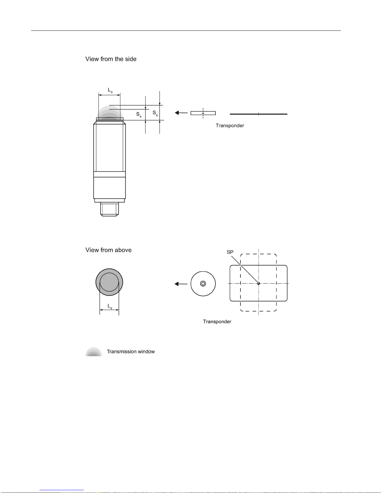
Planning the RF200 system
4.1 Fundamentals of application planning
SIMATIC RF200
28 System Manual, 07/2017, J31069-D0227-U001-A9-7619
Sa
Operating distance between transponder and reader
Sg Limit distance (maximum clear distance between upper surface of the reader and the tran-
sponder, at which the transmission can still function under normal conditions)
L
Diameter of a transmission window
SP
Intersection of the axes of symmetry of the transponder
Figure 4-1 RF210R/RF220R transmission window
The figure below shows the transmission window of the SIMATIC RF240R and SIMATIC
RF260R readers between transponder and reader:

Planning the RF200 system
4.1 Fundamentals of application planning
SIMATIC RF200
System Manual, 07/2017, J31069-D0227-U001-A9-7619
29
Sa
Operating distance between transponder and reader
Sg Limit distance (maximum clear distance between upper surface of the reader and the tran-
sponder, at which the transmission can still function under normal conditions)
L
Length of a transmission window
M
Field centerpoint
Figure 4-2 RF240R/RF260R transmission window
The transponder can be used as soon as the intersection (SP) of the transponder enters the
area of the transmission window.
From the diagrams above, it can also be seen that operation is possible within the area
between S
a
and Sg. The active operating area reduces as the distance increases, and
shrinks to a single point at distance S
g
. Only static mode should thus be used in the area
between S
a
and Sg.

Planning the RF200 system
4.1 Fundamentals of application planning
SIMATIC RF200
30 System Manual, 07/2017, J31069-D0227-U001-A9-7619
4.1.3
Width of the transmission window
Determining the width of the transmission window
The following approximation formula can be used for practical applications:
B:
Width of the transmission window
L:
Length of the transmission window
Tracking tolerances
The width of the transmission window (B) is particularly important for the mechanical tracking
tolerance. The formula for the dwell time is valid without restriction when B is observed.
 Loading...