

Siemens SIMATIC RF185C, SIMATIC RF186C, SIMATIC RF188C Operating Instructions Manual

___________________
___________________
___________________
___________________
___________________
___________________
___________________
___________________
___________________
___________________
___________________
___________________
___________________
___________________
SIMATIC Ident
RFID systems
SIMATIC RF185C, RF186C,
RF188C
Operating Instructions
10/2018
C79000
Introduction
1
Security recommendations
2
Description
3
Mounting
4
Connection
5
Configuring
6
Configuring with the WBM
7
Programming via SIMATIC
controller
8
Programming via the OPC
UA interface
9
Service and maintenance
10
Technical data
11
Dimension drawings
12
Appendix
A
Service & Support
B
-G8976-C512-01

Siemens AG
Division Process Industries and Drives
Postfach 48 48
9
GERMANY
C79000-G8976-C512-01
Ⓟ
Copyright © Siemens AG 2018.
All rights reserved
Legal information
Warning notice system
DANGER
indicates that death or severe personal injury will result if proper precautions are not taken.
WARNING
indicates that death or severe personal injury may result if proper precautions are not taken.
CAUTION
indicates that minor personal injury can result if proper precautions are not taken.
NOTICE
indicates that property damage can result if proper precautions are not taken.
Qualified Personnel
personnel qualified
Proper use of Siemens products
WARNING
Siemens products may only be used for the applications described in the catalog and in the relevant technical
ambient conditions must be complied with. The information in the relevant documentation must be observed.
Trademarks
Disclaimer of Liability
This manual contains notices you have to observe in order to ensure your personal safety, as well as to prevent
damage to property. The notices referring to your personal safety are highlighted in the manual by a safety alert
symbol, notices referring only to property damage have no safety alert symbol. These notices shown below are
graded according to the degree of danger.
If more than one degree of danger is present, the warning notice representing the highest degree of danger will
be used. A notice warning of injury to persons with a safety alert symbol may also include a warning relating to
property damage.
The product/system described in this documentation may be operated only by
task in accordance with the relevant documentation, in particular its warning notices and safety instructions.
Qualified personnel are those who, based on their training and experience, are capable of identifying risks and
avoiding potential hazards when working with these products/systems.
Note the following:
documentation. If products and components from other manufacturers are used, these must be recommended
or approved by Siemens. Proper transport, storage, installation, assembly, commissioning, operation and
maintenance are required to ensure that the products operate safely and without any problems. The permissible
All names identified by ® are registered trademarks of Siemens AG. The remaining trademarks in this publication
may be trademarks whose use by third parties for their own purposes could violate the rights of the owner.
We have reviewed the contents of this publication to ensure consistency with the hardware and software
described. Since variance cannot be precluded entirely, we cannot guarantee full consistency. However, the
information in this publication is reviewed regularly and any necessary corrections are included in subsequent
editions.
for the specific
0026 NÜRNBERG
09/2018 Subject to change

Table of contents
1 Introduction ............................................................................................................................................. 7
2 Security recommendations ...................................................................................................................... 9
3 Description ............................................................................................................................................ 13
4 Mounting ............................................................................................................................................... 19
5 Connection ........................................................................................................................................... 23
6 Configuring ........................................................................................................................................... 43
7 Configuring with the WBM ..................................................................................................................... 53
3.1 Properties of the communications modules ............................................................................ 13
3.2 User-specific procedure .......................................................................................................... 15
3.3 Design ..................................................................................................................................... 17
4.1 Installation dimensions and position ....................................................................................... 19
4.2 Mounting the communications module ................................................................................... 20
5.1 Operation of the CM on grounded/ungrounded power supply ............................................... 26
5.2 Electrical design of the CM ..................................................................................................... 29
5.3 Connect CM to functional ground (PE) ................................................................................... 31
5.3.1 Mounting the CM on a conductive base ................................................................................. 31
5.3.2 Mounting the CM on a non-conductive base .......................................................................... 33
5.4 Connecting the communications module ................................................................................ 35
5.5 Supply voltage and PROFINET IO loop-through .................................................................... 39
5.6 Connecting cables for the CMs ............................................................................................... 40
6.1 Assign the IP address / device name ..................................................................................... 43
6.1.1 Assigning the IP address / device name with STEP 7 ............................................................ 43
6.1.2 Assigning the IP address / device name with the PST ........................................................... 45
6.2 Configuration via PROFINET IO ............................................................................................. 47
6.3 Configuration via OPC UA ...................................................................................................... 51
7.1 Starting WBM .......................................................................................................................... 53
7.2 The WBM ................................................................................................................................ 55
7.3 The menu items of the WBM .................................................................................................. 59
7.3.1 The "Start page" menu item .................................................................................................... 59
7.3.2 The "Settings - General" menu item ....................................................................................... 62
7.3.3 The "Settings - Reader Interface" menu item ......................................................................... 63
7.3.4 The "Settings - Communication" menu item ........................................................................... 66
7.3.5 The "Diagnostics - Log" menu item ........................................................................................ 74
7.3.6 The "Diagnostics - Service Log" menu item ........................................................................... 75
7.3.7 The "Edit transponder" menu item .......................................................................................... 78
SIMATIC RF185C, RF186C, RF188C
Operating Instructions, 10/2018, C79000-G8976-C512-01
3

Table of contents
8 Programming via SIMATIC controller .................................................................................................... 87
9 Programming via the OPC UA interface ................................................................................................ 89
10 Service and maintenance ..................................................................................................................... 113
11 Technical data ..................................................................................................................................... 147
12 Dimension drawings ............................................................................................................................. 149
7.3.8 The "User management" menu item ...................................................................................... 80
7.3.9 The "System" menu item ....................................................................................................... 83
7.3.10 The "Help" menu item ............................................................................................................ 85
9.1 Supported methods/functions ................................................................................................ 90
9.2 OPC UA variables .................................................................................................................. 94
9.2.1 Description of the variables .................................................................................................... 94
9.2.2 ExecuteScan .......................................................................................................................... 95
9.2.3 CommonSettings.................................................................................................................... 95
9.2.4 RfidSettings ............................................................................................................................ 96
9.2.5 Diagnosis ............................................................................................................................... 97
9.2.6 DigitalIOPorts ....................................................................................................................... 103
9.3 OPC UA events .................................................................................................................... 105
9.3.1 Description of the events ..................................................................................................... 105
9.3.2 AutoIdPresenceEvent .......................................................................................................... 106
9.3.3 RfidLastAccessEvent ........................................................................................................... 106
9.3.4 AutoIdLastLogEntryEvent .................................................................................................... 111
10.1 Diagnostics ........................................................................................................................... 113
10.1.1 Diagnostics via the LED display ........................................................................................... 114
10.1.2 Diagnostics via SNMP ......................................................................................................... 117
10.1.3 Diagnostics using the WBM ................................................................................................. 117
10.1.4 Diagnostics over OPC UA .................................................................................................... 118
10.1.5 Diagnostics using the TIA Portal (STEP 7 Basic / Professional) ......................................... 118
10.1.6 Parameterization of the diagnostics ..................................................................................... 121
10.2 Error messages .................................................................................................................... 123
10.2.1 Error messages of the communications module .................................................................. 123
10.2.2 OPC UA error messages ..................................................................................................... 131
10.2.3 Reading out error messages using the WBM ...................................................................... 134
10.3 Firmware update .................................................................................................................. 134
10.3.1 Updating the firmware via WBM .......................................................................................... 135
10.3.2 Update firmware via TIA Portal (STEP 7 Basic / Professional) ........................................... 136
10.3.3 Updating firmware of the readers using the TIA Portal (STEP 7 Basic / Professional) ....... 137
10.4 Factory defaults.................................................................................................................... 139
10.4.1 Restoring the factory settings via WBM ............................................................................... 139
10.4.2 Restoring the factory settings manually ............................................................................... 140
10.5 Module replacement ............................................................................................................ 141
10.5.1 Backup configuration data ................................................................................................... 142
10.5.2 Replacing a module ............................................................................................................. 144
SIMATIC RF185C, RF186C, RF188C
4 Operating Instructions, 10/2018, C79000-G8976-C512-01

Table of contents
A Appendix............................................................................................................................................. 151
B Service & Support ............................................................................................................................... 157
A.1 System planning ................................................................................................................... 151
A.2 Connecting cables ................................................................................................................ 152
A.2.1 Standard cables .................................................................................................................... 152
A.2.2 Custom assembled cables .................................................................................................... 153
A.3 Ordering data ........................................................................................................................ 154
SIMATIC RF185C, RF186C, RF188C
Operating Instructions, 10/2018, C79000-G8976-C512-01
5

Table of contents
SIMATIC RF185C, RF186C, RF188C
6 Operating Instructions, 10/2018, C79000-G8976-C512-01

1
Purpose of these operating instructions
Basic knowledge required
Scope of validity of this documentation
Trademarks
Orientation in the documentation
Abbreviations and naming conventions
Reader
Write/read device (SLG)
Transponder, tag
Data medium, mobile data storage (MDS)
Communications module (CM)
Interface module (ASM)
The information provided in these operating instructions enables you to commission the
RF18xC communications module on a PROFINET IO controller.
These operating instructions assume general knowledge of automation engineering and
identification systems.
These operating instructions are valid for the RF185C, RF186C and RF188C
communications modules as of product version "01" and delivery date as of 10/2018.
The following and possibly other names not identified by the registered trademark sign ® are
registered trademarks of Siemens AG:
SIMATIC ®, SIMATIC RF ®, MOBY ®, RF MANAGER ®, SIMATIC Sensors ®
In addition to these operating instructions, you require the operating instructions for the S7300, S7-400, S7-1200 or S7-1500 controller used.
If you are using SIMATIC S7, you can find information on programming the module as well
as a complete error description in the description of the FB 45 function block, RFID standard
profile and Ident profile.
You can find information on the readers and optical readers to be connected in the intrinsic
safety manual of the respective product family (RF200, RF300, RF600, MV400 and MV500).
You can find the current versions of the various manuals on the pages of the Siemens
Industry Online Support (https://support.industry.siemens.com/cs/ww/en/ps/14970/man
The following terms/abbreviations are used synonymously in this document:
).
SIMATIC RF185C, RF186C, RF188C
Operating Instructions, 10/2018, C79000-G8976-C512-01
7

Introduction
Recycling and disposal
The products are low in harmful substances, can be recycled and meet the requirements of
the Directive 2012/19/EU for disposal of waste electrical and electronic equipment (WEEE).
Do not dispose of the products at public disposal sites.
For environmentally compliant recycling and disposal of your electronic waste, please
contact a company certified for the disposal of electronic waste or your Siemens
representative.
Adhere to the various country-specific regulations.
SIMATIC RF185C, RF186C, RF188C
8 Operating Instructions, 10/2018, C79000-G8976-C512-01

2
General
Physical access
Software (security functions)
Passwords
To prevent unauthorized access, observe the following security recommendations when
working with the communications module and WBM (Web Based Management).
● Check regularly that the device complies with these recommendations and/or other
internal security policies.
● Evaluate your plant as a whole in terms of security. Use a cell protection concept with
suitable products.
● Do not connect the device directly to the Internet. Operate the device within a protected
network area.
● Restrict physical access to the device to qualified personnel.
● Lock unused physical ports (e.g. Ethernet ports) on the device. Unused ports can be used
to access the system without authorization.
● Keep the software up to date. Keep yourself informed regularly about safety updates for
the product.
You can find information about this at Link (http://www.siemens.com/industrialsecurity
● Activate only protocols that you actually need to use the device.
● Limit access to the device using a firewall or rules in an access control list (ACL).
● The configuration files are available in XML format for simple use. Make sure that the
configuration files outside the device are suitably protected. You can, for example,
encrypt the files, store them at a safe location and transfer them only via secure
communications channels.
● Activate user management and create new user profiles.
● Change all default passwords for users before operating the device.
).
● Only use passwords with high password strength. Avoid weak passwords, e.g.
password1, 123456789, abcdefgh.
● Define rules for using devices and assigning passwords.
● Make sure that all passwords are protected and inaccessible to unauthorized personnel.
SIMATIC RF185C, RF186C, RF188C
Operating Instructions, 10/2018, C79000-G8976-C512-01
9

Security recommendations
Keys and certificates
Firmware encryption
Secure/non-secure protocols
● Do not use the same password for different users and systems.
● Update passwords and keys regularly to improve security.
This section deals with the security keys and certificates that you need to set up SSL.
● We urgently recommend creating your own SSL certificates and making them available.
Preset certificates and keys are present in the device.
The preset and automatically created SSL certificates are self-signed. We recommend
using certificates signed either by a reliable external certification authority or an internal
certification authority.
The device has an interface via which you can import certificates and keys.
● We recommend using certificates with a key length of at least 2048 bits.
● If protocols support both certificates and keys, you should favor certificates.
The firmware itself is signed and encrypted. This ensures that only authentic firmware can be
downloaded to the device.
● Check whether it is necessary to use SNMPv1. SNMPv1 is classified as non-secure.
Make use of the possibility to prevent write access. The product offers corresponding
settings for this.
● If SNMP is activated, change the community names. If unrestricted access is not
necessary, limit access via SNMP.
● Use secure protocols if access to the device is not protected by means of physical
safeguards.
The following protocols provide secure alternatives:
HTTP → HTTPS
● To prevent unauthorized access to the device or network, set up appropriate safeguards
against non-secure protocols.
● Enable only the services (protocols) that will actually be used on the device. The same
applies to the installed interfaces/ports. Unused ports could be used to access the
network downstream from the device.
SIMATIC RF185C, RF186C, RF188C
10 Operating Instructions, 10/2018, C79000-G8976-C512-01

Security recommendations
List of available protocols
Protocol
Port number
Default
protocol status
Protocol status
configurable
Port number
configurable
Authentication
Encryption
DHCP
UDP/68
Open
✓
--
No
No
HTTP
TCP/80
Open
--
--
No
No
HTTPS
TCP/443
Open
--
--
Yes
Yes
NTP
UDP/123
Closed
✓
--
No
No
SNMP
UDP/161
Closed
✓
--
No
No
ured)
All available protocols and their ports that are used with SIMATIC RF18xC are listed below.
Table 2- 1 List of available protocols
PROFINET UDP/34964
UDP/4915265535
OPC UA TCP/4840 Open ✓ ✓ Yes (simple,
Open ✓ -- No No
when config-
Explanation of the table:
● Authentication
Specifies whether authentication of the communication partner takes place.
● Encryption
Specifies whether the transfer is encrypted.
Yes (when
configured)
SIMATIC RF185C, RF186C, RF188C
Operating Instructions, 10/2018, C79000-G8976-C512-01
11

Security recommendations
Security information
Siemens provides products and solutions with industrial security functions that support the
secure operation of plants, systems, machines and networks.
In order to protect plants, systems, machines and networks against cyber threats, it is
necessary to implement – and continuously maintain – a holistic, state-of-the-art industrial
security concept. Siemens’ products and solutions constitute one element of such a concept.
Customers are responsible for preventing unauthorized access to their plants, systems,
machines and networks. Such systems, machines and components should only be
connected to an enterprise network or the internet if and to the extent such a connection is
necessary and only when appropriate security measures (e.g. firewalls and/or network
segmentation) are in place.
Additionally, Siemens’ guidance on appropriate security measures should be taken into
account. For additional information on industrial security measures that may be
implemented, please visit
Link: (http://www.siemens.com/industrialsecurity
Siemens’ products and solutions undergo continuous development to make them more
secure. Siemens strongly recommends that product updates are applied as soon as they are
available and that the latest product versions are used. Use of product versions that are no
longer supported, and failure to apply the latest updates may increase customers’ exposure
to cyber threats.
)
To stay informed about product updates, subscribe to the Siemens Industrial Security RSS
Feed under
Link: (http://www.siemens.com/industrialsecurity
)
SIMATIC RF185C, RF186C, RF188C
12 Operating Instructions, 10/2018, C79000-G8976-C512-01
3
3.1
Properties of the communications modules
Area of application
The SIMATIC RF185C, RF186C and RF188C communications modules are designed for
use in all areas of automation. It covers all areas in which SIMATIC Ident RFID readers and
optical readers are operated. The application can run at the field level on a controller, on a
PC or at the IT level. For example, RFID data can be transmitted via the standardized OPC
UA interface to higher-level systems - even parallel to communication with a controller if
required.
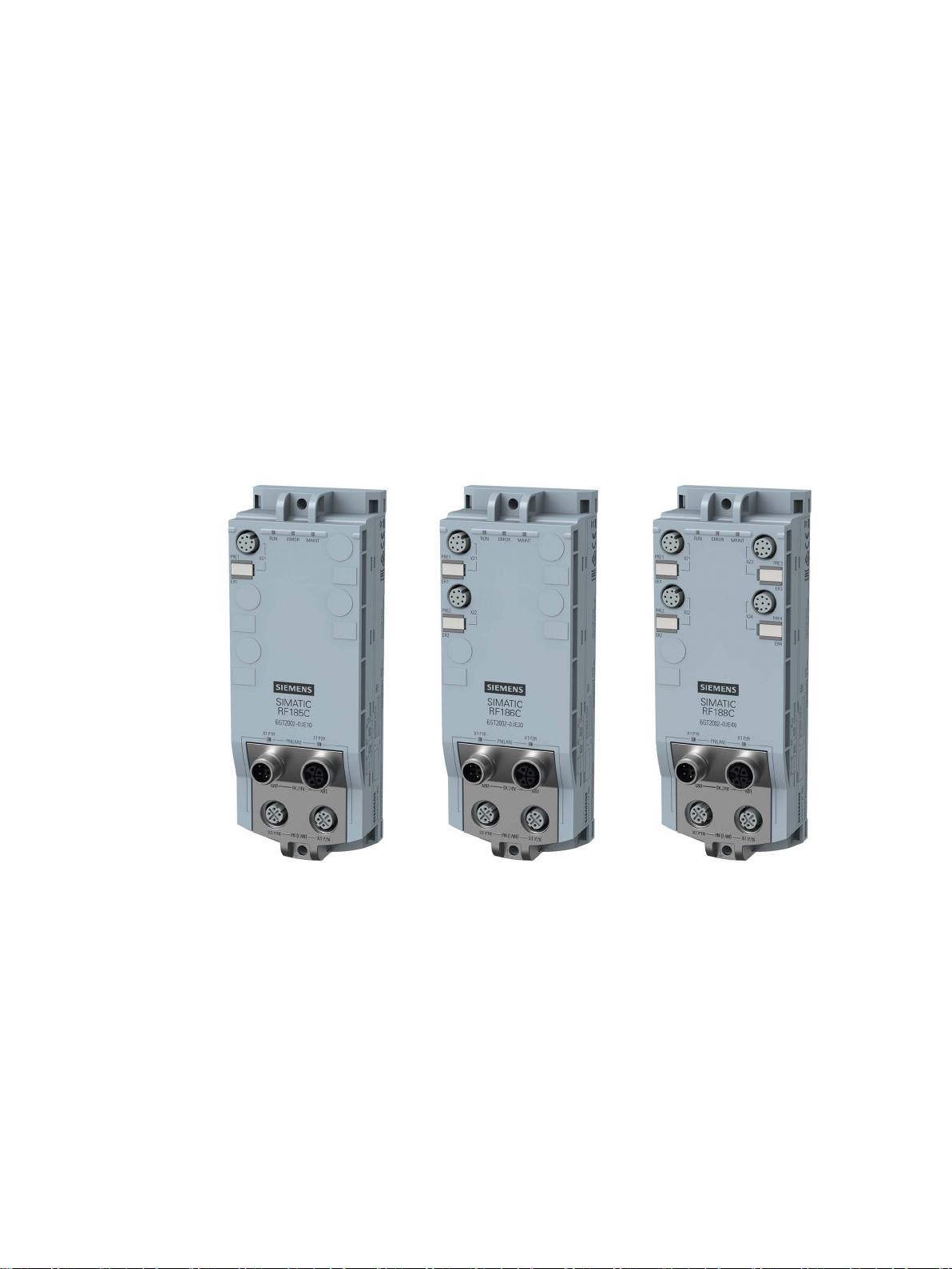
Figure 3-1 Communications modules RF185C, RF186C and RF188C
Due to the high degree of protection, mounting without a protective enclosure is possible
directly near the RFID read points. The small mounting surface of the communications
module facilitates installation in confined spaces.
Two connectors each for Ethernet and power supply allow configuration in a line structure in
addition to a star structure. The innovative L-coded M12 connectors for the power supply
allow a high feed-through current in a line structure. In addition to the familiar configuration
types via TIA Portal and GSDML, these communications modules also feature integrated
Web Based Management (WBM), which enables devices to be set via a standard browser.
During commissioning, diagnostics and maintenance, WBM is a very convenient tool and
displays the status of the connected readers and the data of the recorded transponders.
SIMATIC RF185C, RF186C, RF188C
Operating Instructions, 10/2018, C79000-G8976-C512-01
13

Description
Features
Features
RF185C
RF186C
RF188C
devices
Transfer speed: 19.2 ... 115.2 KB
Transmission speed: 100 Mbps
Degree of protection
IP67
Application protocols
PROFINET IO, OPC UA
diagnostic options
Function blocks
Ident profile, FB 45, faceplate for PCS 7
controllers
controllers
and IEC61131 programming are supported.
NOTICE
Operation in VLANs
3.1 Properties of the communications modules
You can find additional information on the various RFID devices and optical readers on the
Internet on the "Siemens Industry Online Support
(https://support.industry.siemens.com/cs/ww/en/ps/14970/man
)" page.
The following features characterize the RF18xC communications modules:
Table 3- 1 Features of the communications modules
Number of connectable
Supported product
families
Interfaces RS422
Ethernet interface 2x M12, switch integrated
Configuration/
Supported SIMATIC
Supported third-party
Source code of the Ident profile available. All controllers with PROFINET
1 2 4
RF200, RF300, MV400, MV500
STEP 7 (TIA Portal), GSDML, WBM (browser)
S7-300, S7-400, S7-1200, S7-1500
Note that the communications modules cannot be operated in VLANs whose ID is ≠ 0.
SIMATIC RF185C, RF186C, RF188C
14 Operating Instructions, 10/2018, C79000-G8976-C512-01

Description
3.2
User-specific procedure
Procedure as S7 user
Procedure as an OPC UA user
3.2 User-specific procedure
As described in the previous section, the communications modules are designed for different
environments and requirements.
If you operate the communications modules in an automation environment, they are
configured and programmed from the perspective of an S7 user. If you operate the
communications modules in an OPC UA environment, they are configured and programmed
from the perspective of an OPC UA user.
If you want to adapt the communications modules to your requirements, we recommend the
following user-specific procedure:
1. Connect the hardware
You can find information on this in the section "Connection (Page 23)".
2. Assign the IP address / device name
You can find information on this in the section "Assign the IP address / device name
(Page 43)".
3. Configure communications module
You can find information on this in the section "Configuration via PROFINET IO
(Page 47)" or "Configuring with the WBM (Page 53)".
4. Program reader commands
You can find information on this in the section "Programming via SIMATIC controller
(Page 87)".
1. Connect the hardware
You can find information on this in the section "Connection (Page 23)".
2. Assign the IP address / device name
You can find information on this in the section "Assigning the IP address / device name
with the PST (Page 45)".
3. Configure the communications module
You can find information on this in the section "Configuring with the WBM (Page 53)".
4. Program reader commands
You can find information on this in the section "Programming via the OPC UA interface
(Page 89)".
SIMATIC RF185C, RF186C, RF188C
Operating Instructions, 10/2018, C79000-G8976-C512-01
15

Description
Note
Synchronize device time
Note that the time of the device clock corresponds to UTC time and cannot be adj
time zones. Clicking the button transfers the local time stored in your operating system to the
communications module. Because the time synchronized with the PC is lost when the power
supply is terminated, we recommend synchronizing the time with
3.3 Design
usted to
an NTP server.
Later in the document, these symbols will help your orientation and will show you whether
the section is of interest to you or not. Only the sections with user-specific content, in other
words content that is tool/interface-specific, contain these symbols. Sections without these
symbols are general and relevant for both areas of application.
SIMATIC RF185C, RF186C, RF188C
16 Operating Instructions, 10/2018, C79000-G8976-C512-01
Description
3.3
Design
①
⑤
(M12, 4-pin, L-coded)
②
(M12, 8-pin, A-coded)
⑥
(M12, 4-pin, D-coded)
③
Reader LEDs
⑦
Mounting holes and functional ground (PE)
④
PROFINET/Ethernet LEDs
3.3 Design
The following figure shows the basic design of the RF18xC.
Status LEDs
Reader interfaces
Figure 3-2 Design of the communications module
Interface for the power supply
Interface for PROFINET IO
SIMATIC RF185C, RF186C, RF188C
Operating Instructions, 10/2018, C79000-G8976-C512-01
17
Description
Integration
3.3 Design
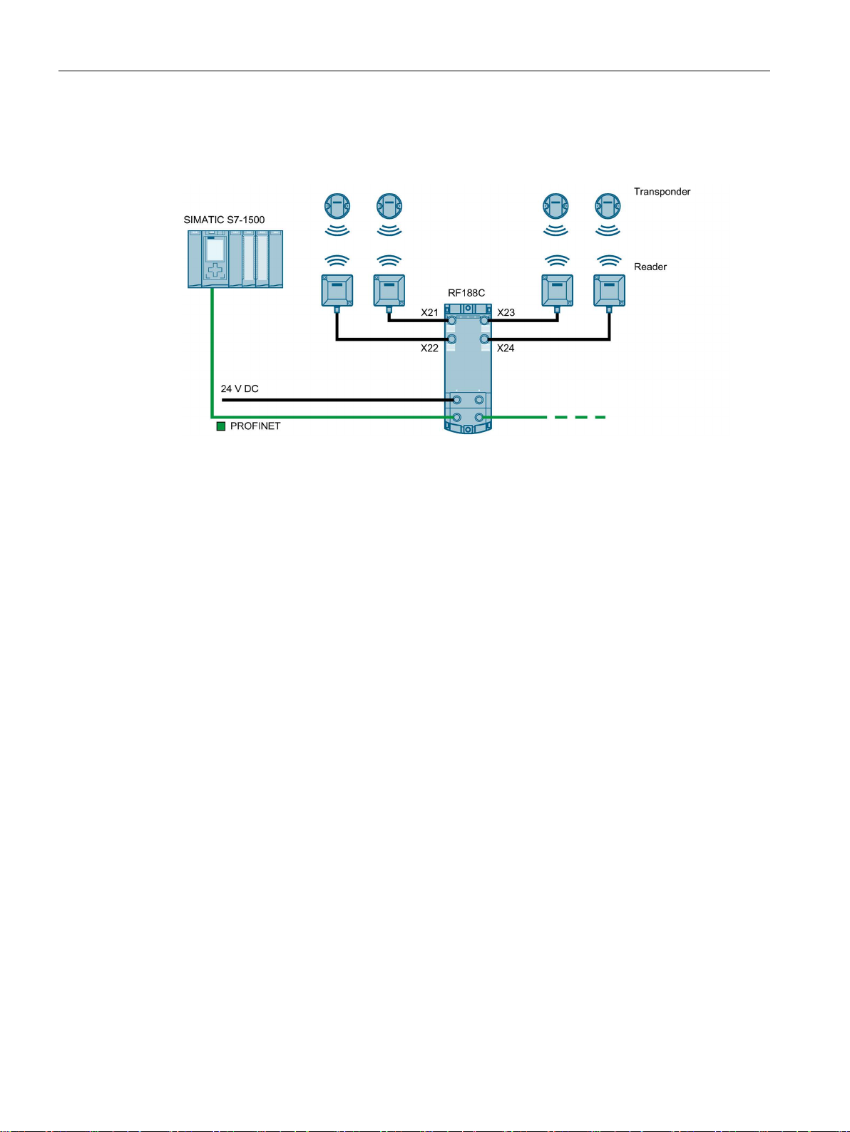
The following figure shows an example of an RF188C connection to an automation system.
Figure 3-3 Configuration graphic RF188C
As of STEP 7 Basic / Professional V15.1, the RF18xC communications modules are
integrated in the TIA Portal. Integration into 3rd-party systems is performed via a GSDML
file. The RF18xC can then be configured via the TIA Portal or another engineering system.
The GSDML file is stored on the communications module and can be downloaded from it
using a Web browser.
SIMATIC RF185C, RF186C, RF188C
18 Operating Instructions, 10/2018, C79000-G8976-C512-01

4
NOTICE
Installation outdoors
irect sunlight,
4.1
Installation dimensions and position
Minimum clearances
Mounting rules
Note
Mounting the communications modules
Only install the communications module when supply voltage
The RF18xC communications modules are designed for easy installation.
Please note that the communications module needs to be installed in a protected area. In
the case of installation outdoors, make sure that the device is protected from d
precipitation and wind.
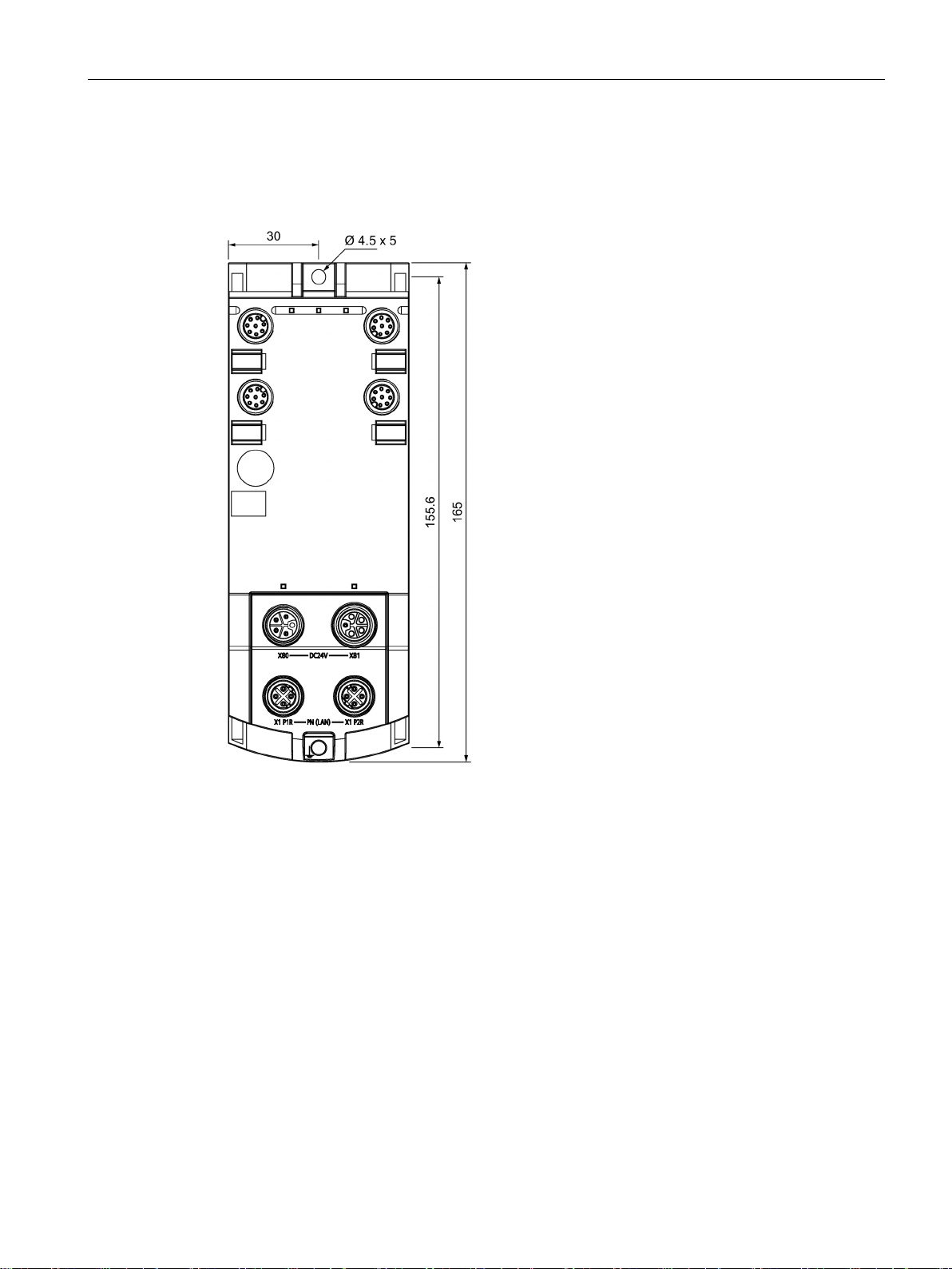
The RF18xC communications modules have the following installation dimensions (W × H ×
D): 60 × 165 × 45 mm.
You can mount the communications modules in any mounting position.
When installing the communications modules, keep a minimum distance of 1 cm from an
adjacent device or another device.
You do not have to observe any special rules when installing the communications modules.
s are switched off.
SIMATIC RF185C, RF186C, RF188C
Operating Instructions, 10/2018, C79000-G8976-C512-01
19

Mounting
4.2
Mounting the communications module
Introduction
Note
Functional ground (PE)
If a grounded metal mounting surface is used, the bottom mounting screw of the RF18xC
module already e
separate ground conductor. If you use the fixing screw as grounding connection, the thread
of the fixing screw or the contact facing of the fastening nut on the base must be unpainted.
This ensures a low
Requirements
Screw type
Description
ISO 1207 / DIN EN ISO 1580
ing to DIN EN ISO 4762
4.2 Mounting the communications module
The communications modules are designed for mounting on a flat, solid surface.
Alternatively, you can use the axially symmetrical drill holes of the modules to fasten them to
an aluminum profile using sliding blocks.
stablishes a reliable ground connection. This eliminates the need for a
-resistance connection.
The following table shows and explains the types of screws you need to mount the modules.
Table 4- 1 Recommended screw types
Cylinder head screw M4 according to DIN EN
Cylinder head screw with M4 hex socket accord-
The minimum screw length should be 35 mm.
If you need washers, use washers conforming to
DIN EN ISO 7089 / DIN EN ISO 7090.
SIMATIC RF185C, RF186C, RF188C
20 Operating Instructions, 10/2018, C79000-G8976-C512-01
Mounting
Procedure
4.2 Mounting the communications module
Fasten the communications module with the screws on a solid level surface. The device
must be screwed (≤ 3 Nm) onto the panel at both fastening points (front top and bottom).
Figure 4-1 Mounting the RF18xC communications module
SIMATIC RF185C, RF186C, RF188C
Operating Instructions, 10/2018, C79000-G8976-C512-01
21
Mounting
Fastener for cable ties
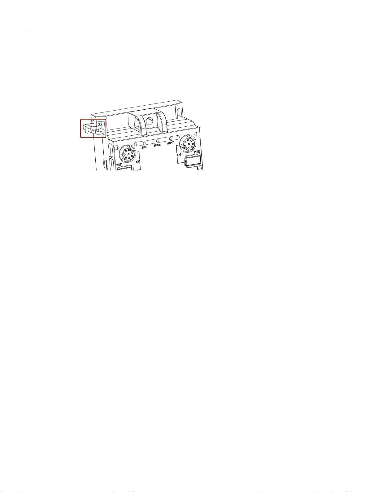
4.2 Mounting the communications module
All communications modules have integrated fastening points for cable ties. The fastening
points are located at all four corners of the modules.
The following figure shows the upper left fastening point for 2.5 mm wide cable ties.
Figure 4-2 Mounting the RF18xC communications module
SIMATIC RF185C, RF186C, RF188C
22 Operating Instructions, 10/2018, C79000-G8976-C512-01
5
Proper use
PROFINET IO connection system
CAUTION
Power supply for devices with PROFINET interfaces
Only use the device for its intended purpose. If unspecified devices are connected to the
RF18xC, the connected device may be destroyed.
You can find detailed information on connecting the RF18xC on PROFINET IO in the
"SIMATIC PROFINET system description
(https://support.industry.siemens.com/cs/ww/en/view/19292127
)".
Modules with PROFINET interfaces may only be operated in LANs (Local Area Networks)
in which all connected devices are equipped with SELV/PELV power supplies (or have
equivalent protection).
A data transfer terminal (modem, for example) is required to access the WAN (Wide Area
Network) in order to ensure compliance with this safety standard.
All supply and signal voltages must be safety extra low voltage (SELV/PELV according to
IEC 61140).
DC 24 V supply: safe (electrical) isolation of extra-low voltage (SELV/PELV according to
EN 61140).
SIMATIC RF185C, RF186C, RF188C
Operating Instructions, 10/2018, C79000-G8976-C512-01
23
Connection
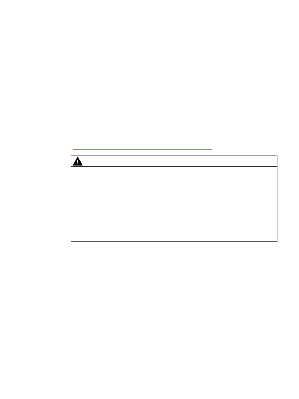
PROFINET IO topology
PROFINET IO communication can be structured as a line topology or star topology. Also
note the information in the section "Supply voltage and PROFINET IO loop-through
(Page 39)".
Figure 5-1 Configuration graphic of a line topology
Figure 5-2 Configuration graphic of a star topology
SIMATIC RF185C, RF186C, RF188C
24 Operating Instructions, 10/2018, C79000-G8976-C512-01
Connection
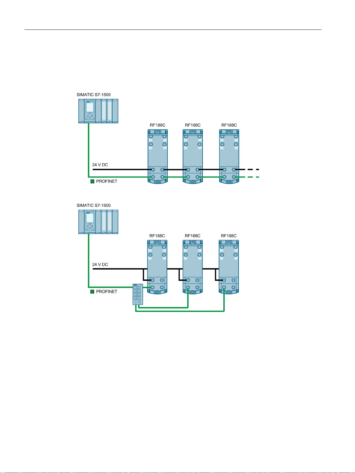
Reader connector system
A reader always occupies one M12 socket on the RF18xC. You can connect the reader to
the communications module using a preassembled cable. The connection cable is available
in lengths of 2, 5, 10, 20 and 50 m as standard. If necessary, these can be extended.
Figure 5-3 Overview of connections
SIMATIC RF185C, RF186C, RF188C
Operating Instructions, 10/2018, C79000-G8976-C512-01
25

Connection
5.1
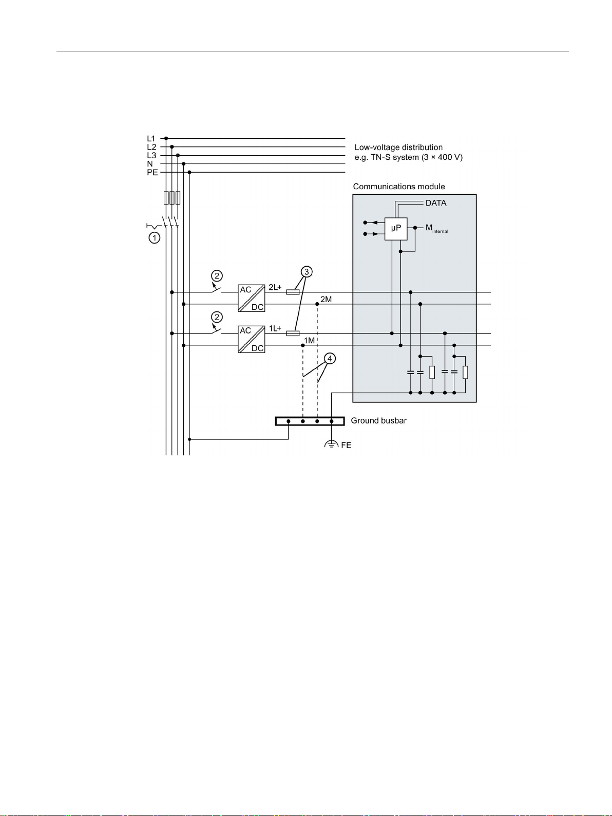
Operation of the CM on grounded/ungrounded power supply
Grounded power supply
Supply voltages
Safe electrical isolation (SELV/PELV according to IEC 60364-4-41)
Setting up RF18xC with grounded reference potential
Setting up RF18xC with ungrounded reference potential
5.1 Operation of the CM on grounded/ungrounded power supply
Below, you can find information on the overall configuration of an RF18xC communications
module on a grounded power supply (TN-S network). The specific subjects discussed here
are:
● Supply voltages of the communications module
● Disconnecting devices, short-circuit and overload protection according to IEC 60364
(corresponds to DIN VDE 0100) and IEC 60204 (corresponds to DIN VDE 0113)
● Load voltage supplies and load circuits
For grounded power supplies, the neutral conductor of the supply system is grounded. A
short-circuit to ground of a live conductor, or of a grounded part of the system, trips the
protective devices.
Two supply voltages are available for the communications module:
● 1L+: Power supply
● 2L+: Load voltage
Note that the power supply (1L+) supplies the communications module and the readers with
power. Load voltage (2L+) has no direct effect on the communications module. This voltage
is looped through to further consumers via the plug-in connectors.
Power supply units/power supply modules with safe electrical isolation are required for
operation of the communications module. This protection is referred to as SELV (Safety
Extra Low Voltage) / PELV (Protective Extra Low Voltage) according to IEC 60364-4-41.
When the communications module is set up with grounded reference potential, any
interference currents that occur are diverted to functional ground. The connections must be
connected externally (connection between 1M and FE).
When the communications module is set up with ungrounded reference potential, any
interference currents occurring are conducted to functional ground via an internal RC
network (no external connection between 1M and FE).
SIMATIC RF185C, RF186C, RF188C
26 Operating Instructions, 10/2018, C79000-G8976-C512-01
Connection
RF18xC in overall configuration
①
Main switch
②
Short-circuit and overvoltage protection
③
Fuses for line protection (automatic circuit breaker for 16 A)
④
connection between 1M, 2M and FE
5.1 Operation of the CM on grounded/ungrounded power supply
The following figure shows the communications module in its overall electrical design.
When setting up the communications module with ungrounded reference potential, there is no
Figure 5-4 Electrical design
SIMATIC RF185C, RF186C, RF188C
Operating Instructions, 10/2018, C79000-G8976-C512-01
27

Connection
Components and protective measures
Screen number
Components
IEC 60364
IEC 60204
actuators
②
circuit breaker.
lines against overcurrent
Insulation monitoring
5.1 Operation of the CM on grounded/ungrounded power supply
A number of components and protective measures are prescribed for plant installations. The
types of components and the degree to which the protective measures are mandatory
depend on the IEC regulation that applies to your plant setup.
The following table shows the components of the electrical design with reference to the
previous figure and compares the IEC regulations.
Table 5- 1 Components of the electrical design
①
③
Isolation monitoring must be provided in the following cases:
● Design of the communications module with ungrounded reference potential
● If hazardous plant states can be expected as a result of faults.
Disconnecting device for
controller, sensors, and
Short-circuit and overload
protection
Circuit breaker
Main switch Disconnector
Single-pole protection of
circuits.
Protect all power supply
lines with a 24 V DC / 16 A
Protection of cables and
Single-pole protection must
be used for a grounded
secondary circuit.
--
SIMATIC RF185C, RF186C, RF188C
28 Operating Instructions, 10/2018, C79000-G8976-C512-01
Connection
5.2
Electrical design of the CM
Electrical isolation
5.2 Electrical design of the CM
In the electrical design of the communications module, electrical isolation is provided
between:
● Load voltage 2L+ and all other circuit components
● Communication interfaces (PROFINET) of the communications module and all other
circuit components
The following figure shows the potential ratios of the communications module.
Figure 5-5 Potential ratios of the communications module
SIMATIC RF185C, RF186C, RF188C
Operating Instructions, 10/2018, C79000-G8976-C512-01
29
Connection
Circuit breaker
Power supply of the assembly
Note
Switching 1L+ and 2L+ on and off
Note that the power supply (1L+) supplies the communications module and the readers with
power. Load voltage (2L+)
is looped through to further consumers via the plug
5.2 Electrical design of the CM
According to IEC 60364, line protection is required, i.e. the supply lines must always be
protected externally.
All supply voltages must be protected with a UL/IEC approved fuse 24 V DC / 16 A (tripping
characteristic type B or C). At ambient temperatures of 40 °C to 55 °C, the power supplies
must be protected with a UL/IEC approved fuse 24 V DC / 12 A.
Two voltage groups are available for the communications module, 1L+ (supply voltage) and
2L+ (load voltage).
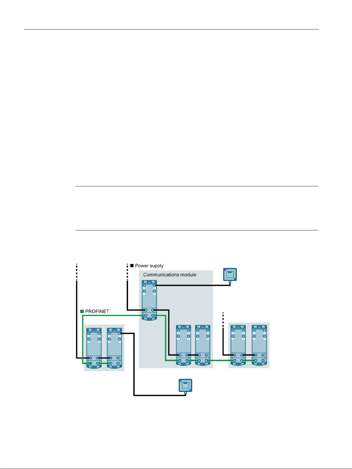
Another power supply may be required in order to supply all communications modules of an
assembly with the required voltage. Another voltage supply of 1L+ and 2L+ may be needed
to form different potential groups, or because the voltage is insufficient for all
communications modules due to the voltage drop. Create a power budget for the selection of
the supply point of the voltage.
has no direct effect on the communications module. This voltage
-in connectors.
The following figure shows a configuration with another voltage supply for the
communications modules. The different potential groups are highlighted in gray.
Figure 5-6 Wiring of the power supply
SIMATIC RF185C, RF186C, RF188C
30 Operating Instructions, 10/2018, C79000-G8976-C512-01
 Loading...