

Page 1

___________________
___________________
___________________
___________________
___________________
___________________
___________________
___________________
___________________
___________________
___________________
___________________
___________________
___________________
SIMATIC Ident
RFID systems
SIMATIC RF185C, RF186C,
RF188C
Operating Instructions
10/2018
C79000
Introduction
1
Security recommendations
2
Description
3
Mounting
4
Connection
5
Configuring
6
Configuring with the WBM
7
Programming via SIMATIC
controller
8
Programming via the OPC
UA interface
9
Service and maintenance
10
Technical data
11
Dimension drawings
12
Appendix
A
Service & Support
B
-G8976-C512-01
Page 2

Siemens AG
Division Process Industries and Drives
Postfach 48 48
9
GERMANY
C79000-G8976-C512-01
Ⓟ
Copyright © Siemens AG 2018.
All rights reserved
Legal information
Warning notice system
DANGER
indicates that death or severe personal injury will result if proper precautions are not taken.
WARNING
indicates that death or severe personal injury may result if proper precautions are not taken.
CAUTION
indicates that minor personal injury can result if proper precautions are not taken.
NOTICE
indicates that property damage can result if proper precautions are not taken.
Qualified Personnel
personnel qualified
Proper use of Siemens products
WARNING
Siemens products may only be used for the applications described in the catalog and in the relevant technical
ambient conditions must be complied with. The information in the relevant documentation must be observed.
Trademarks
Disclaimer of Liability
This manual contains notices you have to observe in order to ensure your personal safety, as well as to prevent
damage to property. The notices referring to your personal safety are highlighted in the manual by a safety alert
symbol, notices referring only to property damage have no safety alert symbol. These notices shown below are
graded according to the degree of danger.
If more than one degree of danger is present, the warning notice representing the highest degree of danger will
be used. A notice warning of injury to persons with a safety alert symbol may also include a warning relating to
property damage.
The product/system described in this documentation may be operated only by
task in accordance with the relevant documentation, in particular its warning notices and safety instructions.
Qualified personnel are those who, based on their training and experience, are capable of identifying risks and
avoiding potential hazards when working with these products/systems.
Note the following:
documentation. If products and components from other manufacturers are used, these must be recommended
or approved by Siemens. Proper transport, storage, installation, assembly, commissioning, operation and
maintenance are required to ensure that the products operate safely and without any problems. The permissible
All names identified by ® are registered trademarks of Siemens AG. The remaining trademarks in this publication
may be trademarks whose use by third parties for their own purposes could violate the rights of the owner.
We have reviewed the contents of this publication to ensure consistency with the hardware and software
described. Since variance cannot be precluded entirely, we cannot guarantee full consistency. However, the
information in this publication is reviewed regularly and any necessary corrections are included in subsequent
editions.
for the specific
0026 NÜRNBERG
09/2018 Subject to change
Page 3

Table of contents
1 Introduction ............................................................................................................................................. 7
2 Security recommendations ...................................................................................................................... 9
3 Description ............................................................................................................................................ 13
4 Mounting ............................................................................................................................................... 19
5 Connection ........................................................................................................................................... 23
6 Configuring ........................................................................................................................................... 43
7 Configuring with the WBM ..................................................................................................................... 53
3.1 Properties of the communications modules ............................................................................ 13
3.2 User-specific procedure .......................................................................................................... 15
3.3 Design ..................................................................................................................................... 17
4.1 Installation dimensions and position ....................................................................................... 19
4.2 Mounting the communications module ................................................................................... 20
5.1 Operation of the CM on grounded/ungrounded power supply ............................................... 26
5.2 Electrical design of the CM ..................................................................................................... 29
5.3 Connect CM to functional ground (PE) ................................................................................... 31
5.3.1 Mounting the CM on a conductive base ................................................................................. 31
5.3.2 Mounting the CM on a non-conductive base .......................................................................... 33
5.4 Connecting the communications module ................................................................................ 35
5.5 Supply voltage and PROFINET IO loop-through .................................................................... 39
5.6 Connecting cables for the CMs ............................................................................................... 40
6.1 Assign the IP address / device name ..................................................................................... 43
6.1.1 Assigning the IP address / device name with STEP 7 ............................................................ 43
6.1.2 Assigning the IP address / device name with the PST ........................................................... 45
6.2 Configuration via PROFINET IO ............................................................................................. 47
6.3 Configuration via OPC UA ...................................................................................................... 51
7.1 Starting WBM .......................................................................................................................... 53
7.2 The WBM ................................................................................................................................ 55
7.3 The menu items of the WBM .................................................................................................. 59
7.3.1 The "Start page" menu item .................................................................................................... 59
7.3.2 The "Settings - General" menu item ....................................................................................... 62
7.3.3 The "Settings - Reader Interface" menu item ......................................................................... 63
7.3.4 The "Settings - Communication" menu item ........................................................................... 66
7.3.5 The "Diagnostics - Log" menu item ........................................................................................ 74
7.3.6 The "Diagnostics - Service Log" menu item ........................................................................... 75
7.3.7 The "Edit transponder" menu item .......................................................................................... 78
SIMATIC RF185C, RF186C, RF188C
Operating Instructions, 10/2018, C79000-G8976-C512-01
3
Page 4

Table of contents
8 Programming via SIMATIC controller .................................................................................................... 87
9 Programming via the OPC UA interface ................................................................................................ 89
10 Service and maintenance ..................................................................................................................... 113
11 Technical data ..................................................................................................................................... 147
12 Dimension drawings ............................................................................................................................. 149
7.3.8 The "User management" menu item ...................................................................................... 80
7.3.9 The "System" menu item ....................................................................................................... 83
7.3.10 The "Help" menu item ............................................................................................................ 85
9.1 Supported methods/functions ................................................................................................ 90
9.2 OPC UA variables .................................................................................................................. 94
9.2.1 Description of the variables .................................................................................................... 94
9.2.2 ExecuteScan .......................................................................................................................... 95
9.2.3 CommonSettings.................................................................................................................... 95
9.2.4 RfidSettings ............................................................................................................................ 96
9.2.5 Diagnosis ............................................................................................................................... 97
9.2.6 DigitalIOPorts ....................................................................................................................... 103
9.3 OPC UA events .................................................................................................................... 105
9.3.1 Description of the events ..................................................................................................... 105
9.3.2 AutoIdPresenceEvent .......................................................................................................... 106
9.3.3 RfidLastAccessEvent ........................................................................................................... 106
9.3.4 AutoIdLastLogEntryEvent .................................................................................................... 111
10.1 Diagnostics ........................................................................................................................... 113
10.1.1 Diagnostics via the LED display ........................................................................................... 114
10.1.2 Diagnostics via SNMP ......................................................................................................... 117
10.1.3 Diagnostics using the WBM ................................................................................................. 117
10.1.4 Diagnostics over OPC UA .................................................................................................... 118
10.1.5 Diagnostics using the TIA Portal (STEP 7 Basic / Professional) ......................................... 118
10.1.6 Parameterization of the diagnostics ..................................................................................... 121
10.2 Error messages .................................................................................................................... 123
10.2.1 Error messages of the communications module .................................................................. 123
10.2.2 OPC UA error messages ..................................................................................................... 131
10.2.3 Reading out error messages using the WBM ...................................................................... 134
10.3 Firmware update .................................................................................................................. 134
10.3.1 Updating the firmware via WBM .......................................................................................... 135
10.3.2 Update firmware via TIA Portal (STEP 7 Basic / Professional) ........................................... 136
10.3.3 Updating firmware of the readers using the TIA Portal (STEP 7 Basic / Professional) ....... 137
10.4 Factory defaults.................................................................................................................... 139
10.4.1 Restoring the factory settings via WBM ............................................................................... 139
10.4.2 Restoring the factory settings manually ............................................................................... 140
10.5 Module replacement ............................................................................................................ 141
10.5.1 Backup configuration data ................................................................................................... 142
10.5.2 Replacing a module ............................................................................................................. 144
SIMATIC RF185C, RF186C, RF188C
4 Operating Instructions, 10/2018, C79000-G8976-C512-01
Page 5

Table of contents
A Appendix............................................................................................................................................. 151
B Service & Support ............................................................................................................................... 157
A.1 System planning ................................................................................................................... 151
A.2 Connecting cables ................................................................................................................ 152
A.2.1 Standard cables .................................................................................................................... 152
A.2.2 Custom assembled cables .................................................................................................... 153
A.3 Ordering data ........................................................................................................................ 154
SIMATIC RF185C, RF186C, RF188C
Operating Instructions, 10/2018, C79000-G8976-C512-01
5
Page 6

Table of contents
SIMATIC RF185C, RF186C, RF188C
6 Operating Instructions, 10/2018, C79000-G8976-C512-01
Page 7

1
Purpose of these operating instructions
Basic knowledge required
Scope of validity of this documentation
Trademarks
Orientation in the documentation
Abbreviations and naming conventions
Reader
Write/read device (SLG)
Transponder, tag
Data medium, mobile data storage (MDS)
Communications module (CM)
Interface module (ASM)
The information provided in these operating instructions enables you to commission the
RF18xC communications module on a PROFINET IO controller.
These operating instructions assume general knowledge of automation engineering and
identification systems.
These operating instructions are valid for the RF185C, RF186C and RF188C
communications modules as of product version "01" and delivery date as of 10/2018.
The following and possibly other names not identified by the registered trademark sign ® are
registered trademarks of Siemens AG:
SIMATIC ®, SIMATIC RF ®, MOBY ®, RF MANAGER ®, SIMATIC Sensors ®
In addition to these operating instructions, you require the operating instructions for the S7300, S7-400, S7-1200 or S7-1500 controller used.
If you are using SIMATIC S7, you can find information on programming the module as well
as a complete error description in the description of the FB 45 function block, RFID standard
profile and Ident profile.
You can find information on the readers and optical readers to be connected in the intrinsic
safety manual of the respective product family (RF200, RF300, RF600, MV400 and MV500).
You can find the current versions of the various manuals on the pages of the Siemens
Industry Online Support (https://support.industry.siemens.com/cs/ww/en/ps/14970/man
The following terms/abbreviations are used synonymously in this document:
).
SIMATIC RF185C, RF186C, RF188C
Operating Instructions, 10/2018, C79000-G8976-C512-01
7
Page 8

Introduction
Recycling and disposal
The products are low in harmful substances, can be recycled and meet the requirements of
the Directive 2012/19/EU for disposal of waste electrical and electronic equipment (WEEE).
Do not dispose of the products at public disposal sites.
For environmentally compliant recycling and disposal of your electronic waste, please
contact a company certified for the disposal of electronic waste or your Siemens
representative.
Adhere to the various country-specific regulations.
SIMATIC RF185C, RF186C, RF188C
8 Operating Instructions, 10/2018, C79000-G8976-C512-01
Page 9

2
General
Physical access
Software (security functions)
Passwords
To prevent unauthorized access, observe the following security recommendations when
working with the communications module and WBM (Web Based Management).
● Check regularly that the device complies with these recommendations and/or other
internal security policies.
● Evaluate your plant as a whole in terms of security. Use a cell protection concept with
suitable products.
● Do not connect the device directly to the Internet. Operate the device within a protected
network area.
● Restrict physical access to the device to qualified personnel.
● Lock unused physical ports (e.g. Ethernet ports) on the device. Unused ports can be used
to access the system without authorization.
● Keep the software up to date. Keep yourself informed regularly about safety updates for
the product.
You can find information about this at Link (http://www.siemens.com/industrialsecurity
● Activate only protocols that you actually need to use the device.
● Limit access to the device using a firewall or rules in an access control list (ACL).
● The configuration files are available in XML format for simple use. Make sure that the
configuration files outside the device are suitably protected. You can, for example,
encrypt the files, store them at a safe location and transfer them only via secure
communications channels.
● Activate user management and create new user profiles.
● Change all default passwords for users before operating the device.
).
● Only use passwords with high password strength. Avoid weak passwords, e.g.
password1, 123456789, abcdefgh.
● Define rules for using devices and assigning passwords.
● Make sure that all passwords are protected and inaccessible to unauthorized personnel.
SIMATIC RF185C, RF186C, RF188C
Operating Instructions, 10/2018, C79000-G8976-C512-01
9
Page 10

Security recommendations
Keys and certificates
Firmware encryption
Secure/non-secure protocols
● Do not use the same password for different users and systems.
● Update passwords and keys regularly to improve security.
This section deals with the security keys and certificates that you need to set up SSL.
● We urgently recommend creating your own SSL certificates and making them available.
Preset certificates and keys are present in the device.
The preset and automatically created SSL certificates are self-signed. We recommend
using certificates signed either by a reliable external certification authority or an internal
certification authority.
The device has an interface via which you can import certificates and keys.
● We recommend using certificates with a key length of at least 2048 bits.
● If protocols support both certificates and keys, you should favor certificates.
The firmware itself is signed and encrypted. This ensures that only authentic firmware can be
downloaded to the device.
● Check whether it is necessary to use SNMPv1. SNMPv1 is classified as non-secure.
Make use of the possibility to prevent write access. The product offers corresponding
settings for this.
● If SNMP is activated, change the community names. If unrestricted access is not
necessary, limit access via SNMP.
● Use secure protocols if access to the device is not protected by means of physical
safeguards.
The following protocols provide secure alternatives:
HTTP → HTTPS
● To prevent unauthorized access to the device or network, set up appropriate safeguards
against non-secure protocols.
● Enable only the services (protocols) that will actually be used on the device. The same
applies to the installed interfaces/ports. Unused ports could be used to access the
network downstream from the device.
SIMATIC RF185C, RF186C, RF188C
10 Operating Instructions, 10/2018, C79000-G8976-C512-01
Page 11

Security recommendations
List of available protocols
Protocol
Port number
Default
protocol status
Protocol status
configurable
Port number
configurable
Authentication
Encryption
DHCP
UDP/68
Open
✓
--
No
No
HTTP
TCP/80
Open
--
--
No
No
HTTPS
TCP/443
Open
--
--
Yes
Yes
NTP
UDP/123
Closed
✓
--
No
No
SNMP
UDP/161
Closed
✓
--
No
No
ured)
All available protocols and their ports that are used with SIMATIC RF18xC are listed below.
Table 2- 1 List of available protocols
PROFINET UDP/34964
UDP/4915265535
OPC UA TCP/4840 Open ✓ ✓ Yes (simple,
Open ✓ -- No No
when config-
Explanation of the table:
● Authentication
Specifies whether authentication of the communication partner takes place.
● Encryption
Specifies whether the transfer is encrypted.
Yes (when
configured)
SIMATIC RF185C, RF186C, RF188C
Operating Instructions, 10/2018, C79000-G8976-C512-01
11
Page 12

Security recommendations
Security information
Siemens provides products and solutions with industrial security functions that support the
secure operation of plants, systems, machines and networks.
In order to protect plants, systems, machines and networks against cyber threats, it is
necessary to implement – and continuously maintain – a holistic, state-of-the-art industrial
security concept. Siemens’ products and solutions constitute one element of such a concept.
Customers are responsible for preventing unauthorized access to their plants, systems,
machines and networks. Such systems, machines and components should only be
connected to an enterprise network or the internet if and to the extent such a connection is
necessary and only when appropriate security measures (e.g. firewalls and/or network
segmentation) are in place.
Additionally, Siemens’ guidance on appropriate security measures should be taken into
account. For additional information on industrial security measures that may be
implemented, please visit
Link: (http://www.siemens.com/industrialsecurity
Siemens’ products and solutions undergo continuous development to make them more
secure. Siemens strongly recommends that product updates are applied as soon as they are
available and that the latest product versions are used. Use of product versions that are no
longer supported, and failure to apply the latest updates may increase customers’ exposure
to cyber threats.
)
To stay informed about product updates, subscribe to the Siemens Industrial Security RSS
Feed under
Link: (http://www.siemens.com/industrialsecurity
)
SIMATIC RF185C, RF186C, RF188C
12 Operating Instructions, 10/2018, C79000-G8976-C512-01
Page 13
3
3.1
Properties of the communications modules
Area of application
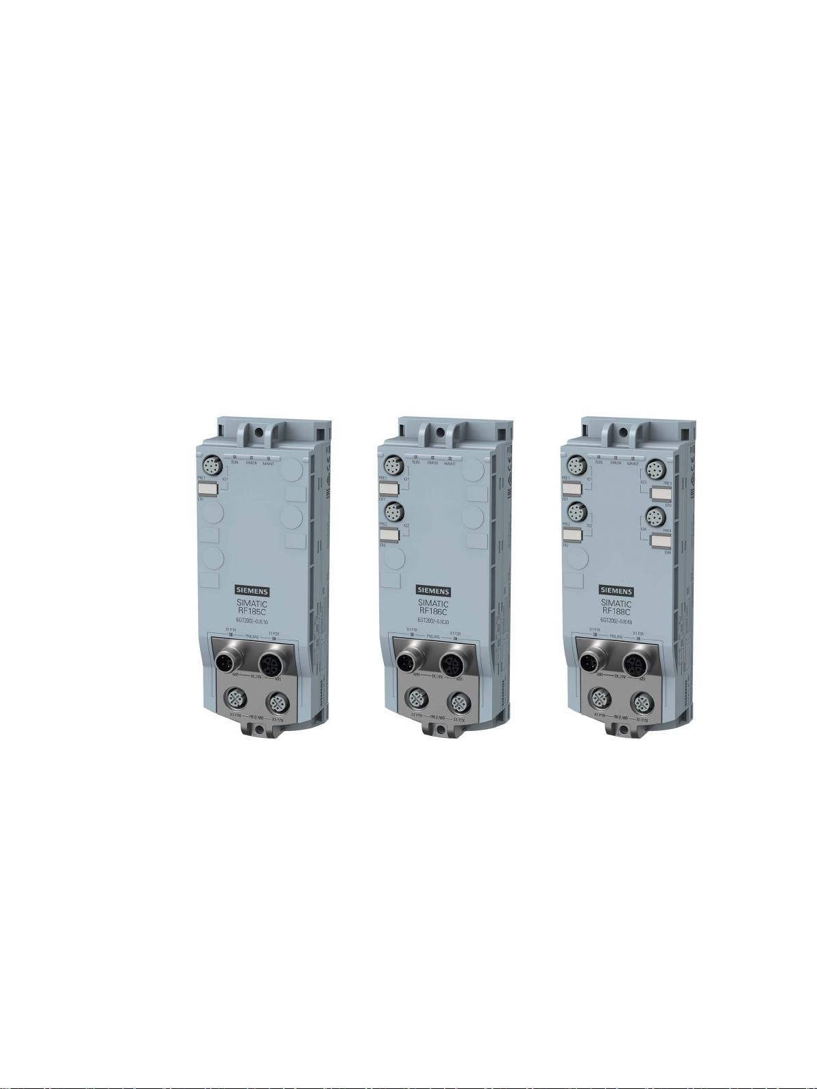
The SIMATIC RF185C, RF186C and RF188C communications modules are designed for
use in all areas of automation. It covers all areas in which SIMATIC Ident RFID readers and
optical readers are operated. The application can run at the field level on a controller, on a
PC or at the IT level. For example, RFID data can be transmitted via the standardized OPC
UA interface to higher-level systems - even parallel to communication with a controller if
required.
Figure 3-1 Communications modules RF185C, RF186C and RF188C
Due to the high degree of protection, mounting without a protective enclosure is possible
directly near the RFID read points. The small mounting surface of the communications
module facilitates installation in confined spaces.
Two connectors each for Ethernet and power supply allow configuration in a line structure in
addition to a star structure. The innovative L-coded M12 connectors for the power supply
allow a high feed-through current in a line structure. In addition to the familiar configuration
types via TIA Portal and GSDML, these communications modules also feature integrated
Web Based Management (WBM), which enables devices to be set via a standard browser.
During commissioning, diagnostics and maintenance, WBM is a very convenient tool and
displays the status of the connected readers and the data of the recorded transponders.
SIMATIC RF185C, RF186C, RF188C
Operating Instructions, 10/2018, C79000-G8976-C512-01
13
Page 14

Description
Features
Features
RF185C
RF186C
RF188C
devices
Transfer speed: 19.2 ... 115.2 KB
Transmission speed: 100 Mbps
Degree of protection
IP67
Application protocols
PROFINET IO, OPC UA
diagnostic options
Function blocks
Ident profile, FB 45, faceplate for PCS 7
controllers
controllers
and IEC61131 programming are supported.
NOTICE
Operation in VLANs
3.1 Properties of the communications modules
You can find additional information on the various RFID devices and optical readers on the
Internet on the "Siemens Industry Online Support
(https://support.industry.siemens.com/cs/ww/en/ps/14970/man
)" page.
The following features characterize the RF18xC communications modules:
Table 3- 1 Features of the communications modules
Number of connectable
Supported product
families
Interfaces RS422
Ethernet interface 2x M12, switch integrated
Configuration/
Supported SIMATIC
Supported third-party
Source code of the Ident profile available. All controllers with PROFINET
1 2 4
RF200, RF300, MV400, MV500
STEP 7 (TIA Portal), GSDML, WBM (browser)
S7-300, S7-400, S7-1200, S7-1500
Note that the communications modules cannot be operated in VLANs whose ID is ≠ 0.
SIMATIC RF185C, RF186C, RF188C
14 Operating Instructions, 10/2018, C79000-G8976-C512-01
Page 15

Description
3.2
User-specific procedure
Procedure as S7 user
Procedure as an OPC UA user
3.2 User-specific procedure
As described in the previous section, the communications modules are designed for different
environments and requirements.
If you operate the communications modules in an automation environment, they are
configured and programmed from the perspective of an S7 user. If you operate the
communications modules in an OPC UA environment, they are configured and programmed
from the perspective of an OPC UA user.
If you want to adapt the communications modules to your requirements, we recommend the
following user-specific procedure:
1. Connect the hardware
You can find information on this in the section "Connection (Page 23)".
2. Assign the IP address / device name
You can find information on this in the section "Assign the IP address / device name
(Page 43)".
3. Configure communications module
You can find information on this in the section "Configuration via PROFINET IO
(Page 47)" or "Configuring with the WBM (Page 53)".
4. Program reader commands
You can find information on this in the section "Programming via SIMATIC controller
(Page 87)".
1. Connect the hardware
You can find information on this in the section "Connection (Page 23)".
2. Assign the IP address / device name
You can find information on this in the section "Assigning the IP address / device name
with the PST (Page 45)".
3. Configure the communications module
You can find information on this in the section "Configuring with the WBM (Page 53)".
4. Program reader commands
You can find information on this in the section "Programming via the OPC UA interface
(Page 89)".
SIMATIC RF185C, RF186C, RF188C
Operating Instructions, 10/2018, C79000-G8976-C512-01
15
Page 16

Description
Note
Synchronize device time
Note that the time of the device clock corresponds to UTC time and cannot be adj
time zones. Clicking the button transfers the local time stored in your operating system to the
communications module. Because the time synchronized with the PC is lost when the power
supply is terminated, we recommend synchronizing the time with
3.3 Design
usted to
an NTP server.
Later in the document, these symbols will help your orientation and will show you whether
the section is of interest to you or not. Only the sections with user-specific content, in other
words content that is tool/interface-specific, contain these symbols. Sections without these
symbols are general and relevant for both areas of application.
SIMATIC RF185C, RF186C, RF188C
16 Operating Instructions, 10/2018, C79000-G8976-C512-01
Page 17
Description
3.3
Design
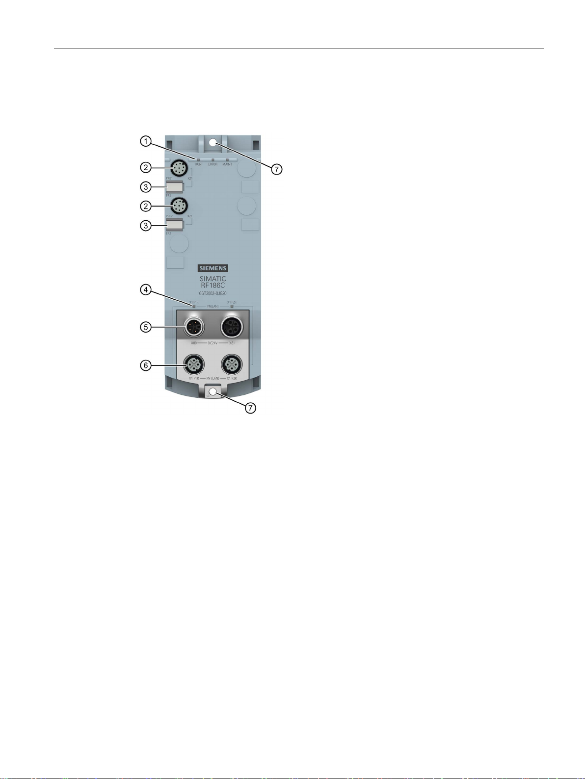
①
⑤
(M12, 4-pin, L-coded)
②
(M12, 8-pin, A-coded)
⑥
(M12, 4-pin, D-coded)
③
Reader LEDs
⑦
Mounting holes and functional ground (PE)
④
PROFINET/Ethernet LEDs
3.3 Design
The following figure shows the basic design of the RF18xC.
Status LEDs
Reader interfaces
Figure 3-2 Design of the communications module
Interface for the power supply
Interface for PROFINET IO
SIMATIC RF185C, RF186C, RF188C
Operating Instructions, 10/2018, C79000-G8976-C512-01
17
Page 18
Description
Integration
3.3 Design
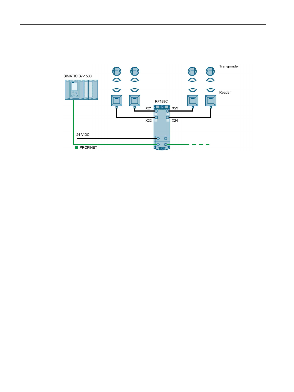
The following figure shows an example of an RF188C connection to an automation system.
Figure 3-3 Configuration graphic RF188C
As of STEP 7 Basic / Professional V15.1, the RF18xC communications modules are
integrated in the TIA Portal. Integration into 3rd-party systems is performed via a GSDML
file. The RF18xC can then be configured via the TIA Portal or another engineering system.
The GSDML file is stored on the communications module and can be downloaded from it
using a Web browser.
SIMATIC RF185C, RF186C, RF188C
18 Operating Instructions, 10/2018, C79000-G8976-C512-01
Page 19

4
NOTICE
Installation outdoors
irect sunlight,
4.1
Installation dimensions and position
Minimum clearances
Mounting rules
Note
Mounting the communications modules
Only install the communications module when supply voltage
The RF18xC communications modules are designed for easy installation.
Please note that the communications module needs to be installed in a protected area. In
the case of installation outdoors, make sure that the device is protected from d
precipitation and wind.
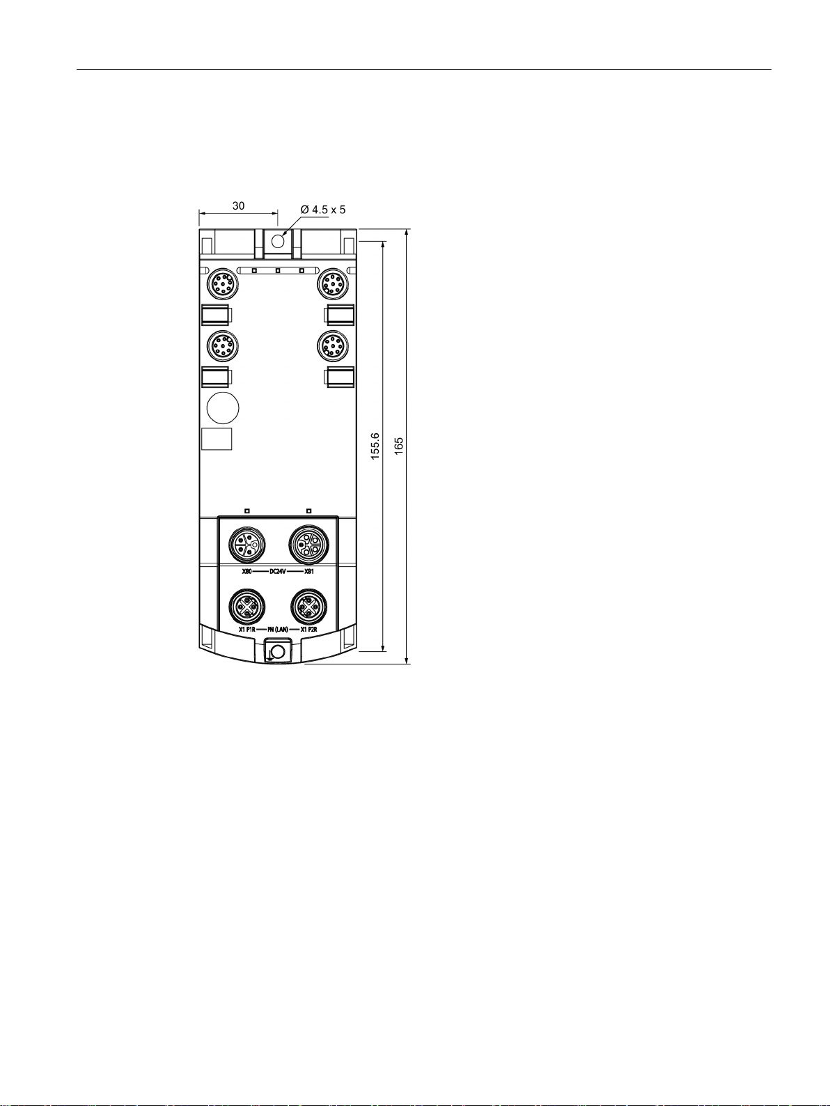
The RF18xC communications modules have the following installation dimensions (W × H ×
D): 60 × 165 × 45 mm.
You can mount the communications modules in any mounting position.
When installing the communications modules, keep a minimum distance of 1 cm from an
adjacent device or another device.
You do not have to observe any special rules when installing the communications modules.
s are switched off.
SIMATIC RF185C, RF186C, RF188C
Operating Instructions, 10/2018, C79000-G8976-C512-01
19
Page 20

Mounting
4.2
Mounting the communications module
Introduction
Note
Functional ground (PE)
If a grounded metal mounting surface is used, the bottom mounting screw of the RF18xC
module already e
separate ground conductor. If you use the fixing screw as grounding connection, the thread
of the fixing screw or the contact facing of the fastening nut on the base must be unpainted.
This ensures a low
Requirements
Screw type
Description
ISO 1207 / DIN EN ISO 1580
ing to DIN EN ISO 4762
4.2 Mounting the communications module
The communications modules are designed for mounting on a flat, solid surface.
Alternatively, you can use the axially symmetrical drill holes of the modules to fasten them to
an aluminum profile using sliding blocks.
stablishes a reliable ground connection. This eliminates the need for a
-resistance connection.
The following table shows and explains the types of screws you need to mount the modules.
Table 4- 1 Recommended screw types
Cylinder head screw M4 according to DIN EN
Cylinder head screw with M4 hex socket accord-
The minimum screw length should be 35 mm.
If you need washers, use washers conforming to
DIN EN ISO 7089 / DIN EN ISO 7090.
SIMATIC RF185C, RF186C, RF188C
20 Operating Instructions, 10/2018, C79000-G8976-C512-01
Page 21
Mounting
Procedure
4.2 Mounting the communications module
Fasten the communications module with the screws on a solid level surface. The device
must be screwed (≤ 3 Nm) onto the panel at both fastening points (front top and bottom).
Figure 4-1 Mounting the RF18xC communications module
SIMATIC RF185C, RF186C, RF188C
Operating Instructions, 10/2018, C79000-G8976-C512-01
21
Page 22
Mounting
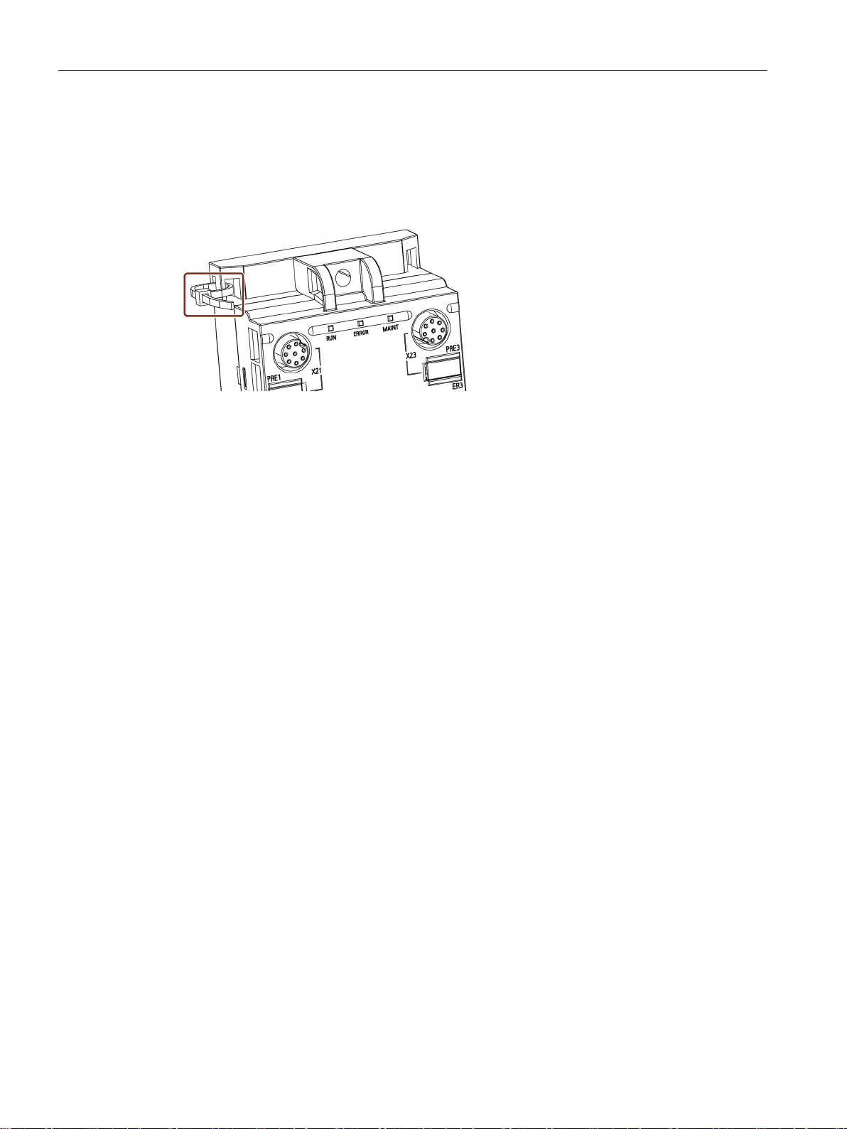
Fastener for cable ties
4.2 Mounting the communications module
All communications modules have integrated fastening points for cable ties. The fastening
points are located at all four corners of the modules.
The following figure shows the upper left fastening point for 2.5 mm wide cable ties.
Figure 4-2 Mounting the RF18xC communications module
SIMATIC RF185C, RF186C, RF188C
22 Operating Instructions, 10/2018, C79000-G8976-C512-01
Page 23
5
Proper use
PROFINET IO connection system
CAUTION
Power supply for devices with PROFINET interfaces
Only use the device for its intended purpose. If unspecified devices are connected to the
RF18xC, the connected device may be destroyed.
You can find detailed information on connecting the RF18xC on PROFINET IO in the
"SIMATIC PROFINET system description
(https://support.industry.siemens.com/cs/ww/en/view/19292127
)".
Modules with PROFINET interfaces may only be operated in LANs (Local Area Networks)
in which all connected devices are equipped with SELV/PELV power supplies (or have
equivalent protection).
A data transfer terminal (modem, for example) is required to access the WAN (Wide Area
Network) in order to ensure compliance with this safety standard.
All supply and signal voltages must be safety extra low voltage (SELV/PELV according to
IEC 61140).
DC 24 V supply: safe (electrical) isolation of extra-low voltage (SELV/PELV according to
EN 61140).
SIMATIC RF185C, RF186C, RF188C
Operating Instructions, 10/2018, C79000-G8976-C512-01
23
Page 24
Connection
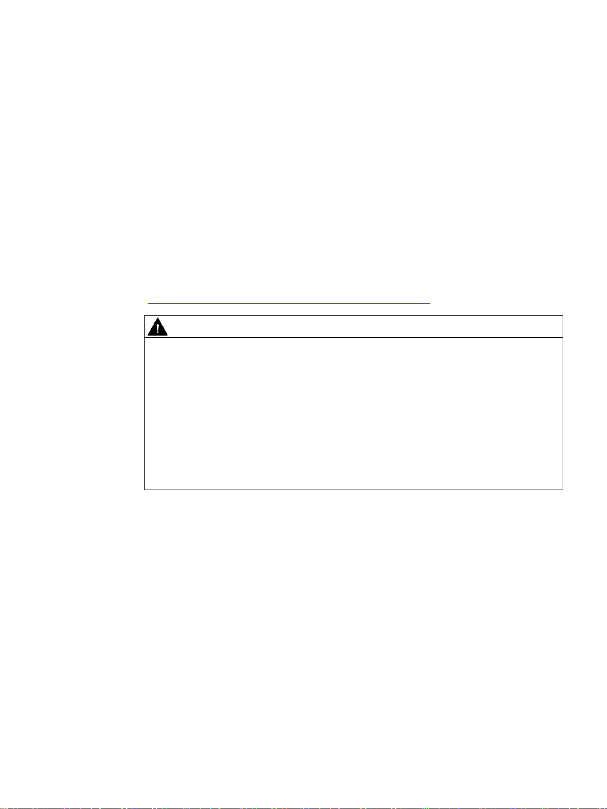
PROFINET IO topology
PROFINET IO communication can be structured as a line topology or star topology. Also
note the information in the section "Supply voltage and PROFINET IO loop-through
(Page 39)".
Figure 5-1 Configuration graphic of a line topology
Figure 5-2 Configuration graphic of a star topology
SIMATIC RF185C, RF186C, RF188C
24 Operating Instructions, 10/2018, C79000-G8976-C512-01
Page 25
Connection
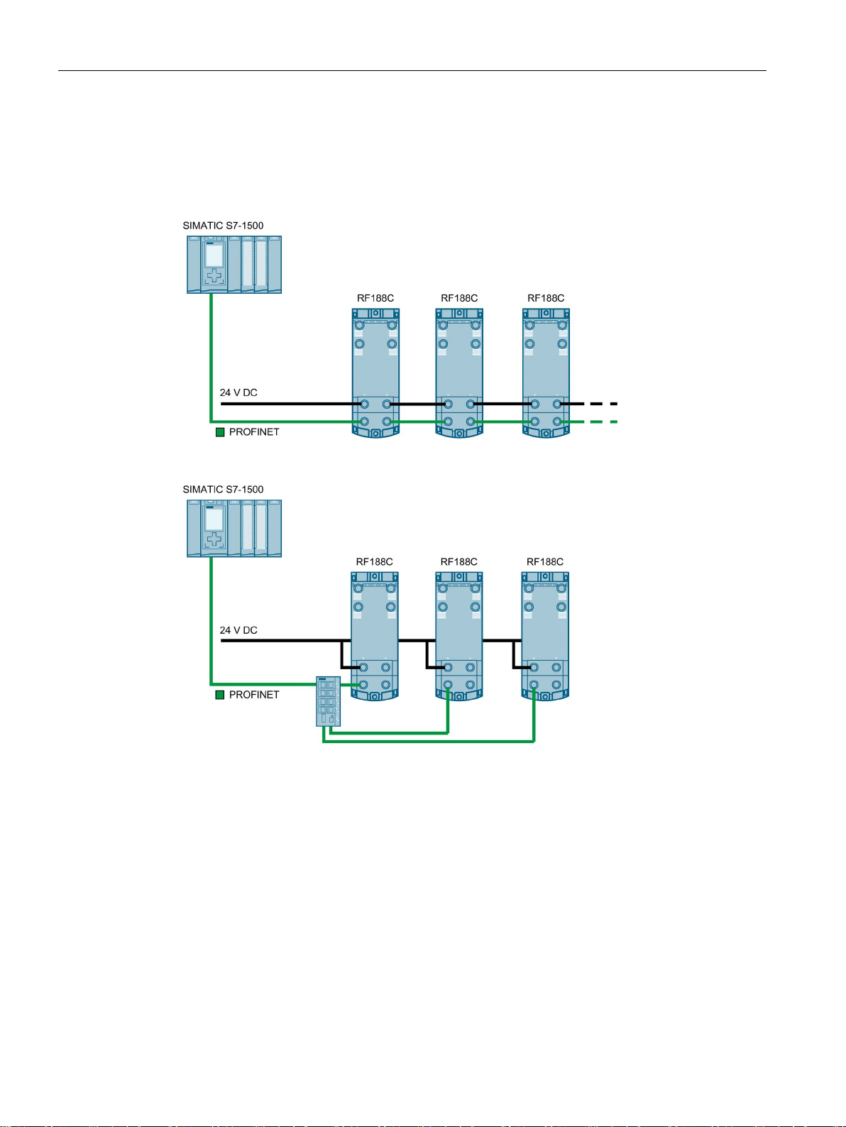
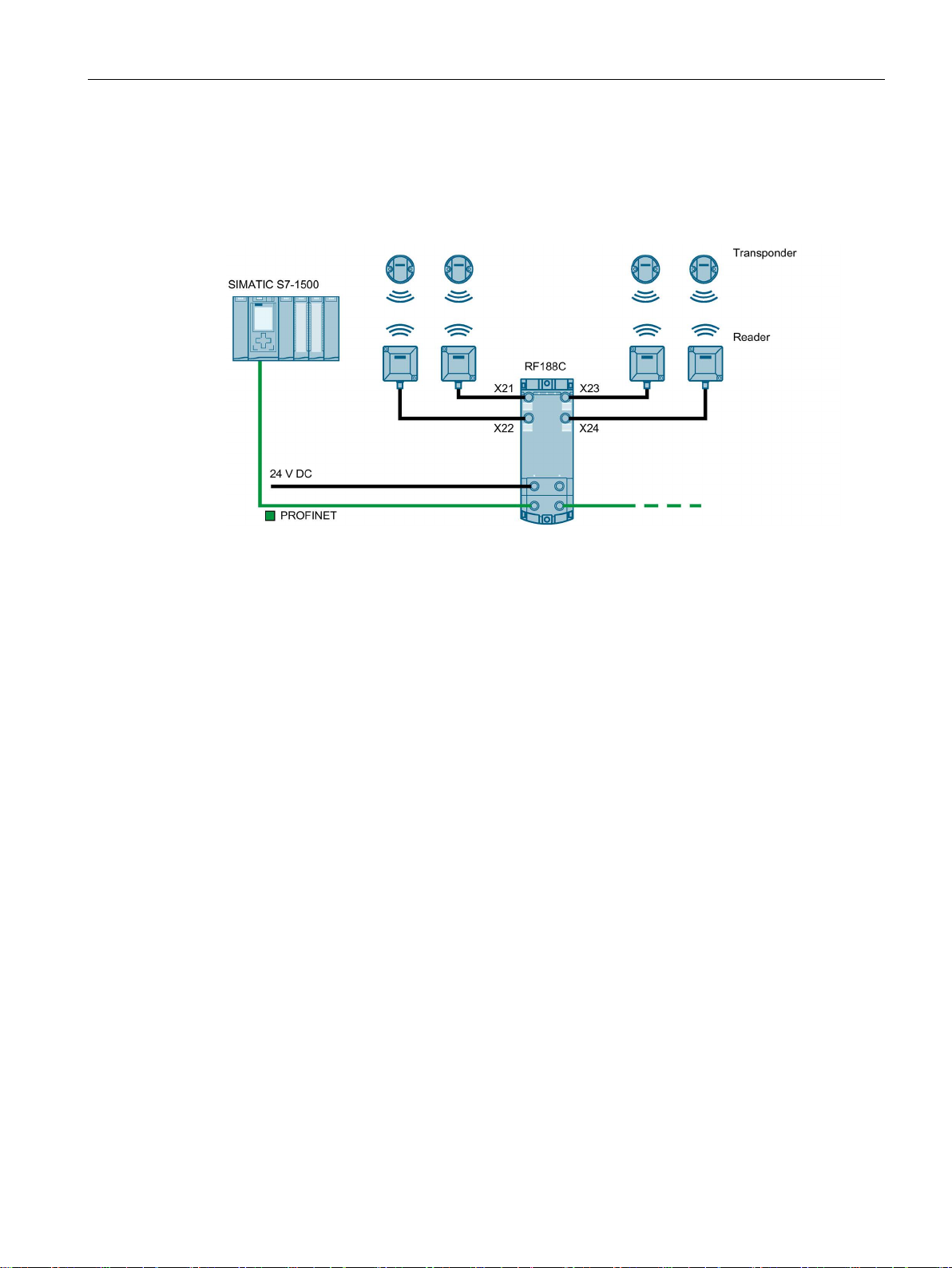
Reader connector system
A reader always occupies one M12 socket on the RF18xC. You can connect the reader to
the communications module using a preassembled cable. The connection cable is available
in lengths of 2, 5, 10, 20 and 50 m as standard. If necessary, these can be extended.
Figure 5-3 Overview of connections
SIMATIC RF185C, RF186C, RF188C
Operating Instructions, 10/2018, C79000-G8976-C512-01
25
Page 26

Connection
5.1
Operation of the CM on grounded/ungrounded power supply
Grounded power supply
Supply voltages
Safe electrical isolation (SELV/PELV according to IEC 60364-4-41)
Setting up RF18xC with grounded reference potential
Setting up RF18xC with ungrounded reference potential
5.1 Operation of the CM on grounded/ungrounded power supply
Below, you can find information on the overall configuration of an RF18xC communications
module on a grounded power supply (TN-S network). The specific subjects discussed here
are:
● Supply voltages of the communications module
● Disconnecting devices, short-circuit and overload protection according to IEC 60364
(corresponds to DIN VDE 0100) and IEC 60204 (corresponds to DIN VDE 0113)
● Load voltage supplies and load circuits
For grounded power supplies, the neutral conductor of the supply system is grounded. A
short-circuit to ground of a live conductor, or of a grounded part of the system, trips the
protective devices.
Two supply voltages are available for the communications module:
● 1L+: Power supply
● 2L+: Load voltage
Note that the power supply (1L+) supplies the communications module and the readers with
power. Load voltage (2L+) has no direct effect on the communications module. This voltage
is looped through to further consumers via the plug-in connectors.
Power supply units/power supply modules with safe electrical isolation are required for
operation of the communications module. This protection is referred to as SELV (Safety
Extra Low Voltage) / PELV (Protective Extra Low Voltage) according to IEC 60364-4-41.
When the communications module is set up with grounded reference potential, any
interference currents that occur are diverted to functional ground. The connections must be
connected externally (connection between 1M and FE).
When the communications module is set up with ungrounded reference potential, any
interference currents occurring are conducted to functional ground via an internal RC
network (no external connection between 1M and FE).
SIMATIC RF185C, RF186C, RF188C
26 Operating Instructions, 10/2018, C79000-G8976-C512-01
Page 27
Connection
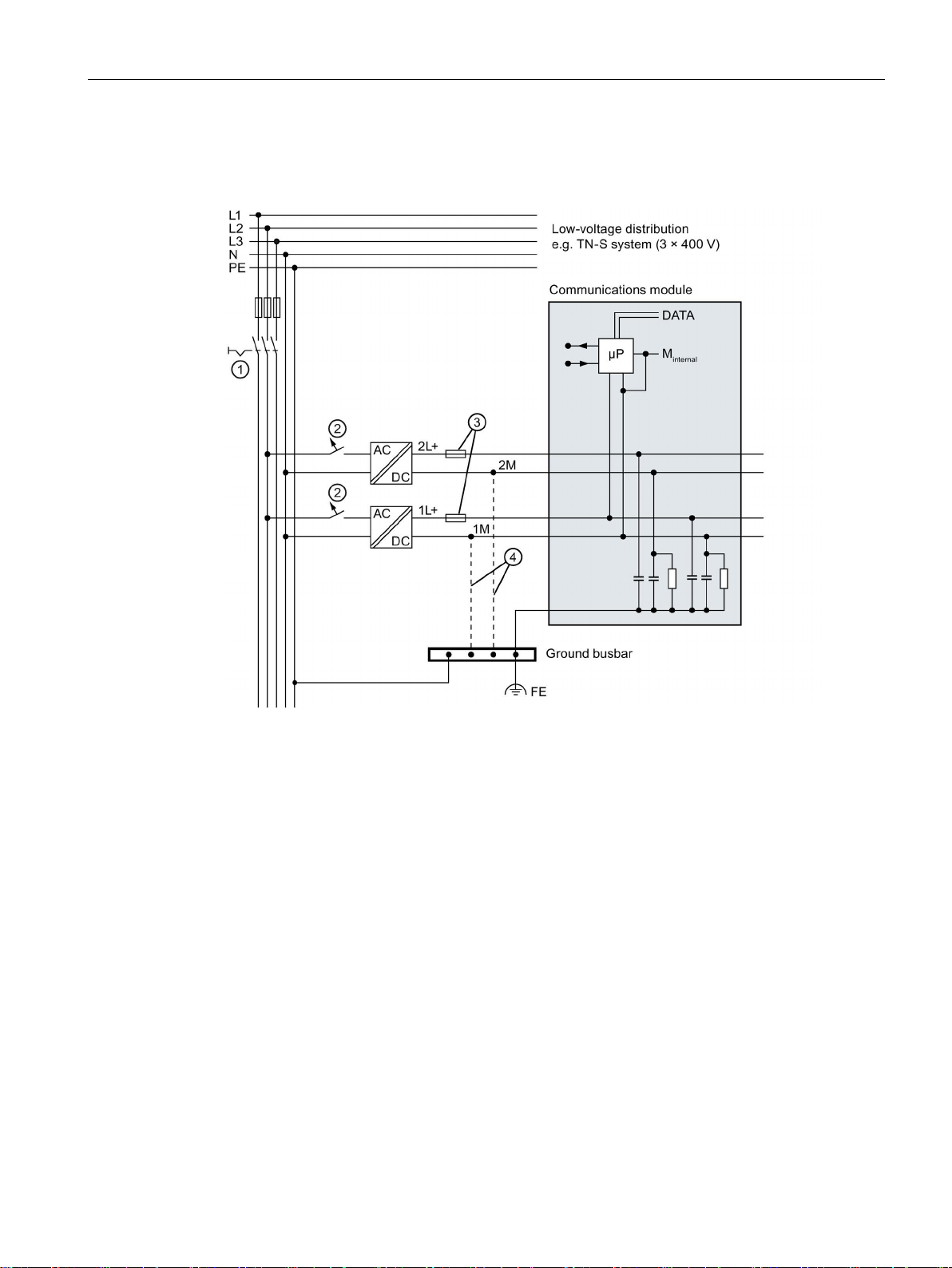
RF18xC in overall configuration
①
Main switch
②
Short-circuit and overvoltage protection
③
Fuses for line protection (automatic circuit breaker for 16 A)
④
connection between 1M, 2M and FE
5.1 Operation of the CM on grounded/ungrounded power supply
The following figure shows the communications module in its overall electrical design.
When setting up the communications module with ungrounded reference potential, there is no
Figure 5-4 Electrical design
SIMATIC RF185C, RF186C, RF188C
Operating Instructions, 10/2018, C79000-G8976-C512-01
27
Page 28

Connection
Components and protective measures
Screen number
Components
IEC 60364
IEC 60204
actuators
②
circuit breaker.
lines against overcurrent
Insulation monitoring
5.1 Operation of the CM on grounded/ungrounded power supply
A number of components and protective measures are prescribed for plant installations. The
types of components and the degree to which the protective measures are mandatory
depend on the IEC regulation that applies to your plant setup.
The following table shows the components of the electrical design with reference to the
previous figure and compares the IEC regulations.
Table 5- 1 Components of the electrical design
①
③
Isolation monitoring must be provided in the following cases:
● Design of the communications module with ungrounded reference potential
● If hazardous plant states can be expected as a result of faults.
Disconnecting device for
controller, sensors, and
Short-circuit and overload
protection
Circuit breaker
Main switch Disconnector
Single-pole protection of
circuits.
Protect all power supply
lines with a 24 V DC / 16 A
Protection of cables and
Single-pole protection must
be used for a grounded
secondary circuit.
--
SIMATIC RF185C, RF186C, RF188C
28 Operating Instructions, 10/2018, C79000-G8976-C512-01
Page 29
Connection
5.2
Electrical design of the CM
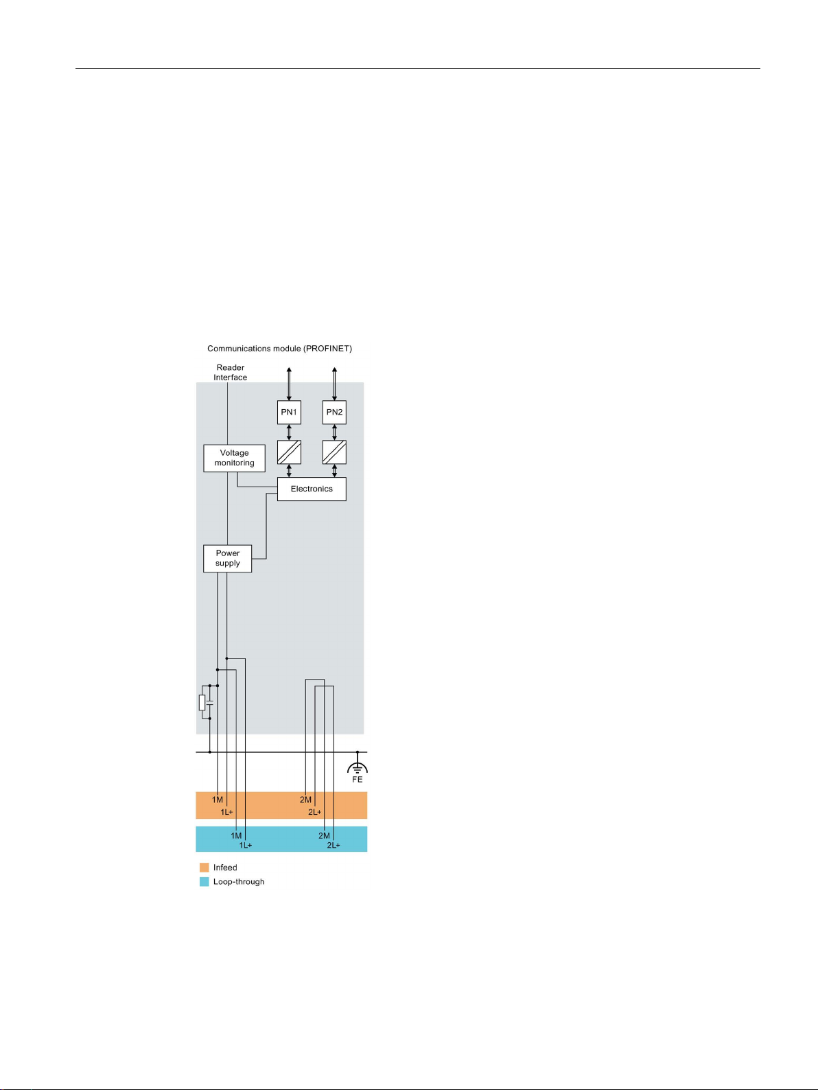
Electrical isolation
5.2 Electrical design of the CM
In the electrical design of the communications module, electrical isolation is provided
between:
● Load voltage 2L+ and all other circuit components
● Communication interfaces (PROFINET) of the communications module and all other
circuit components
The following figure shows the potential ratios of the communications module.
Figure 5-5 Potential ratios of the communications module
SIMATIC RF185C, RF186C, RF188C
Operating Instructions, 10/2018, C79000-G8976-C512-01
29
Page 30
Connection
Circuit breaker
Power supply of the assembly
Note
Switching 1L+ and 2L+ on and off
Note that the power supply (1L+) supplies the communications module and the readers with
power. Load voltage (2L+)
is looped through to further consumers via the plug
5.2 Electrical design of the CM
According to IEC 60364, line protection is required, i.e. the supply lines must always be
protected externally.
All supply voltages must be protected with a UL/IEC approved fuse 24 V DC / 16 A (tripping
characteristic type B or C). At ambient temperatures of 40 °C to 55 °C, the power supplies
must be protected with a UL/IEC approved fuse 24 V DC / 12 A.
Two voltage groups are available for the communications module, 1L+ (supply voltage) and
2L+ (load voltage).
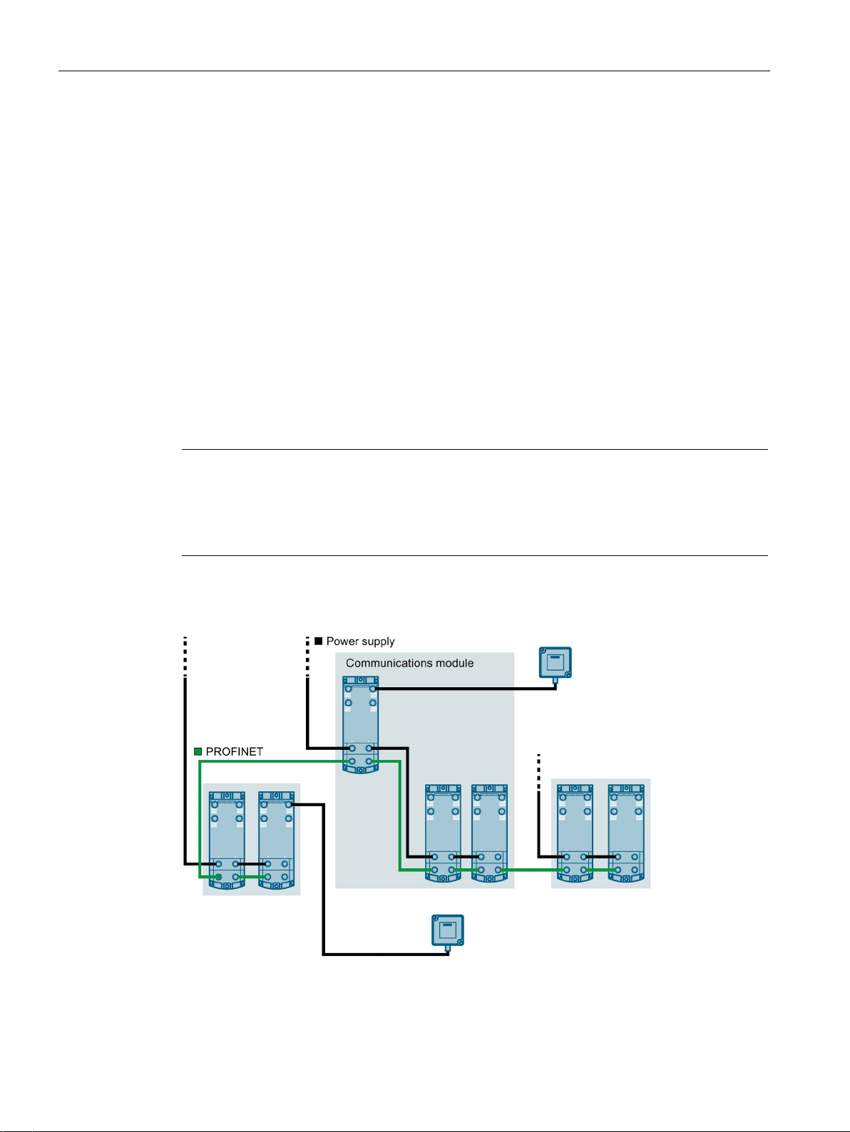
Another power supply may be required in order to supply all communications modules of an
assembly with the required voltage. Another voltage supply of 1L+ and 2L+ may be needed
to form different potential groups, or because the voltage is insufficient for all
communications modules due to the voltage drop. Create a power budget for the selection of
the supply point of the voltage.
has no direct effect on the communications module. This voltage
-in connectors.
The following figure shows a configuration with another voltage supply for the
communications modules. The different potential groups are highlighted in gray.
Figure 5-6 Wiring of the power supply
SIMATIC RF185C, RF186C, RF188C
30 Operating Instructions, 10/2018, C79000-G8976-C512-01
Page 31

Connection
5.3
Connect CM to functional ground (PE)
Protection against external electrical influences
5.3.1
Mounting the CM on a conductive base
Requirement
Required tools
Accessories required
5.3 Connect CM to functional ground (PE)
You need to connect the RF18xC communications module to functional ground (PE). For this
purpose, a grounding screw for one ground conductor is provided on the communications
module.
If a grounded metal mounting surface is used, the bottom mounting screw of the RF18xC
module already establishes a reliable ground connection. This eliminates the need for a
separate ground conductor.
The connection to functional ground (PE) is also required to deflect the interference currents
and for electromagnetic compatibility.
Below is a description of what you must pay attention to in terms of protection against
electrical impacts and/or faults:
● In all plants or systems in which the communications module is installed, you must ensure
that the plant or the system for dissipating electromagnetic interference is connected to
functional ground.
● For supply, signal and bus lines, you must ensure that the laying of the lines and the
installation is correct.
● For signal and bus lines, you must ensure that a wire/cable breakage or a cross-circuit
does not lead to undefined states of the plant or system.
Conductive base for mounting the module.
You need the following tool to connect to the functional ground:
● Screwdriver
You need the following accessories to connect to the functional ground:
● Fastening screw (M4) and washer
SIMATIC RF185C, RF186C, RF188C
Operating Instructions, 10/2018, C79000-G8976-C512-01
31
Page 32

Connection
Mounting
NOTICE
Grounding with a conductive mounting base
①
Grounded, metallic base
②
Unpainted thread or nut support
5.3 Connect CM to functional ground (PE)
Proceed as follows to connect the communications module to functional ground via a
conductive mounting base:
1. Drill 2 mounting holes with a distance of 155.6 mm.
2. Screw the module together with the M4 fastening screws with a torque of 1.2 Nm.
If you fasten the communications module to a conductive, grounded base, the lower
fastening screw provides a conductive connection to the ground potential.
Ensure there is a low-impedance connection between the communications module and the
conductive base and between the conductive base and functional ground.
Figure 5-7 Mounting the CM on a conductive base
SIMATIC RF185C, RF186C, RF188C
32 Operating Instructions, 10/2018, C79000-G8976-C512-01
Page 33

Connection
5.3.2
Mounting the CM on a non-conductive base
Requirement
Required tools
Accessories required
5.3 Connect CM to functional ground (PE)
Non-conductive base for mounting the module.
You need the following tools to connect to the functional ground:
● Screwdriver
● Stripping tool
● Crimp tool
To connect to functional ground with a non-conductive mounting base, you can need the
following accessories:
● Fastening screw (M4) and washer
● Cable lug suitable for M4 screws
● Ground conductor cable (copper braid) with a minimum cross-section of 4 mm
2
SIMATIC RF185C, RF186C, RF188C
Operating Instructions, 10/2018, C79000-G8976-C512-01
33
Page 34

Connection
Mounting
NOTICE
Grounding with non-conductive mounting base
5.3 Connect CM to functional ground (PE)
Proceed as follows to connect the communications module to functional ground via a ground
conductor:
1. Drill 2 mounting holes with a distance of 155.6 mm.
2. Insulate the ground conductor.
3. Attach the cable lug to the ground conductor.
4. Screw the module and the cable lug together with the M4 fastening screws with a torque
of 1.2 Nm.
Ensure a low impedance connection between the communications module and functional
ground.
Figure 5-8 Mounting the CM on a non-conductive base / connection to functional ground
SIMATIC RF185C, RF186C, RF188C
34 Operating Instructions, 10/2018, C79000-G8976-C512-01
Page 35

Connection
5.4
Connecting the communications module
Interfaces
①
⑤
(M12, 4-pin, L-coded)
②
(M12, 8-pin, A-coded)
⑥
(M12, 4-pin, D-coded)
③
Reader LEDs
⑦
Mounting holes and functional ground (PE)
④
PROFINET/Ethernet LEDs
Requirement
5.4 Connecting the communications module
Status LEDs
Reader interfaces
X21-X24
Figure 5-9 Design of the communications module
You can loop the supply voltages and PROFINET IO via the M12 round sockets ⑤ + ⑥.
The pin assignments of the various interfaces are lasered on the side of each
communications module at the factory.
Only wire the communications module when the supply voltage is switched off.
Interface for the power supply
X80, X81
Interface for PROFINET IO
X1 P1R, X1 P2R
SIMATIC RF185C, RF186C, RF188C
Operating Instructions, 10/2018, C79000-G8976-C512-01
35
Page 36

Connection
Required tools
Note
Using preassembled cables
When connecting the supply voltage, we recommend the cables specified in section
"
If you want to make the cable yourself, ensure that the cable has a conductor cross
of 1.5
Accessories required
Wiring interfaces/connectors
Pin
Assignment
View of M12 socket, 4-pin
1
Data line TxP
2
Data line RxP
3
Data line TxN
5.4 Connecting the communications module
When using preassembled cables, you need the following tool:
● Torque wrench set (e.g. from Peres; M12/M8, can be set; PER091) for wiring the reader
connections
Ordering data (Page 154)" (5 x 1.5 mm2 preassembled).
-section
mm2.
When using cables that are not preassembled, you need the following tool:
● Stripping tool
● Screwdriver for wiring M12 connectors
You need the following accessories:
● PROFINET IO connection
M12 plug (4-pin, D-coded) and 4-wire Ethernet cable (Twisted Pair, shielded)
● Connection: Power supply
M12 plug (4-pin, L-coded) and 4-wire cable (4 x 1.5 mm
● Reader connection
M12 plug (8-pin, A-coded) and 8-wire cable (8 x 24 AWG)
You can find the associated article numbers in the section "Ordering data (Page 154)".
The following tables show the pin assignment for the M12 interface/connector.
Table 5- 2 Pin assignment PROFINET IO; M12 socket (4-pin, D-coded)
2
or 4 x 2 mm2)
4 Data line RxN
SIMATIC RF185C, RF186C, RF188C
36 Operating Instructions, 10/2018, C79000-G8976-C512-01
Page 37

Connection
Pin
Assignment
View of M12 socket, 4-pin
1
L1: +24 V (brown)
3
N1: 0 V (blue)
Pin
Assignment
View of M12 socket, 8-pin
RS422
RS232
1
+24 V
+24 V
2
-RxD
--
3
0 V
0 V 4 +RxD
RxD
5
+TxD
+5 V
7
--
TxD
5.4 Connecting the communications module
Table 5- 3 Pin assignment power supply; M12 socket (4-pin, L-coded)
2 N2: 0 V load supply (white)
4 L2: +24 V (black)
Table 5- 4 Pin assignment reader interface; M12 socket (8-pin, A-coded)
6 -TxD --
8 Functional ground
(PE) / shield
Functional ground
(PE) / shield
SIMATIC RF185C, RF186C, RF188C
Operating Instructions, 10/2018, C79000-G8976-C512-01
37
Page 38

Connection
Connect the plug
NOTICE
Ensuring the degree of protection
①
Connector for the reader connection (M12, 8-pin, A-coded)
②
Connector for the power supply (M12, 5-pin, L-coded)
③
Connector for PROFINET IO connection (M12, 4-pin, D-coded)
5.4 Connecting the communications module
Proceed as follows to connect the device:
1. Push the respective plug into the corresponding round socket on the communications
module.
Ensure that the correct stop is provided between the connector and bush (groove and
spring).
2. Fasten the connector by tightening the knurled locking ring.
To guarantee the degree of protection, all connectors need to be tightened with ≃ 1.0 Nm.
You need to close all unused sockets with M12 sealing caps to ensure IP65 or IP67
degree of protection. You can find the order data of the sealing caps in the section
"Ordering data (Page 154)".
Figure 5-10 Connect the plug
SIMATIC RF185C, RF186C, RF188C
38 Operating Instructions, 10/2018, C79000-G8976-C512-01
Page 39

Connection
5.5
Supply voltage and PROFINET IO loop-through
Notes for wiring
NOTICE
Damage to the device
5.5 Supply voltage and PROFINET IO loop-through
The RF18xC communications modules each have two M12 connections for the supply
voltage and PROFINET IO. Supply takes place via the 1st connection, the supply voltage
and PROFINET IO can be forwarded to another device via the 2nd connection.
Figure 5-11 Supply voltage and PROFINET IO loop-through
● When wiring your assembly, you need to take into account the effect of the cable length
on the supply voltage at the RF18xC.
● The maximum supply current of the communications module is 16 A at 1L+ and 2L+ for a
maximum ambient temperature of 40 °C. At ambient temperatures of 40 °C to 55 °C, the
maximum supply current is 12 A. These values must not be exceeded.
● Adhere to the current carrying capacity of the connected cables, which depends on the
conductor material, the conductor cross-section and the ambient temperature.
Make sure to use a conductor cross-section of at least 1.5 mm².
If you do not observe the maximum permissible supply current and the cable crosssection required, this may result in the cable isolation and contacts overheating and in
the device being damaged.
SIMATIC RF185C, RF186C, RF188C
Operating Instructions, 10/2018, C79000-G8976-C512-01
39
Page 40

Connection
5.6
Connecting cables for the CMs
Effect of cable length on the supply voltage
CAUTION
Observe the maximum supply currents
5.6 Connecting cables for the CMs
When wiring your assembly, you need to take into account the effect of the cable length on
the supply voltage of the communications module.
The maximum supply current of the communications module is 16 A at 1L+ and 2L+ for a
maximum ambient temperature of 40 °C. At ambient temperatures of 40 °C to 55 °C, the
maximum supply current is 12 A. These values must not be exceeded.
If you do not comply with the maximum supply currents and the required line crosssections, an increased supply current can lead to overheating of the cable insulation and
the contacts. This can result in damage to the communications module.
The following figure shows the voltage drop as a function of the cable length for 16 A, using
2
the example of a copper cable with ∅ 1.5 mm
.
Figure 5-12 Voltage drop with a cable cross-section of 1.5 mm
To estimate the voltage drop in your communications module, you must add the voltage
SIMATIC RF185C, RF186C, RF188C
drops of the cables.
40 Operating Instructions, 10/2018, C79000-G8976-C512-01
2
Page 41

Connection
Example
5.6 Connecting cables for the CMs
With 16 A, the voltage drop via the two L-coded M12 plug-in connectors and in the
communications module is approximately 0.2 V. The value can vary significantly depending
on the plug connection or condition.
2
When using a 7 m power cable with ∅ 1.5 mm
, the voltage drop is approx. 2.6 V with a 16 A
load.
SIMATIC RF185C, RF186C, RF188C
Operating Instructions, 10/2018, C79000-G8976-C512-01
41
Page 42

Connection
5.6 Connecting cables for the CMs
SIMATIC RF185C, RF186C, RF188C
42 Operating Instructions, 10/2018, C79000-G8976-C512-01
Page 43

6
6.1
Assign the IP address / device name
6.1.1
Assigning the IP address / device name with STEP 7
Requirements
Procedure
To ensure functioning communication between the controller and the communications
module, you must assign unique IP addresses or device names to the individual
communications modules. Depending on the infrastructure in which you want to operate the
communications module, the following different procedures are available:
● Operate the communications module as an S7 user in an automation environment.
The unique assignment is made via the device name using the TIA Portal (from STEP 7
Basic / Professional V15).
● Operate the communications module as OPC UA user in an IT environment.
The unique assignment is based on DHCP or the IP address using the Primary Setup
Tool V4.2 or higher (PST).
Each communications module receives a unique device identification (MAC address) at the
factory.
STEP 7 Basic / Professional is installed, the communications module is connected and has
started up.
Proceed as follows to assign a unique device name to the communications module:
1. Open the TIA Portal with "Start > All Programs > Siemens Automation > TIA Portal Vxx".
2. Create a new project.
3. Change to the Project view.
4. Using the project tree, insert a SIMATIC controller in the project with the "Add new
device" menu command.
Reaction: The device view opens and the controller is displayed.
5. Go to the network view and drag the communications module from the hardware catalog
into the project.
6. Assign the communications module to the controller.
7. Right-click on the communications module.
SIMATIC RF185C, RF186C, RF188C
Operating Instructions, 10/2018, C79000-G8976-C512-01
43
Page 44

Configuring
6.1 Assign the IP address / device name
8. In the shortcut menu, select the menu command "Assign device name".
Reaction: The "Assign PROFINET device name" window opens.
Figure 6-1 Assign device name
9. Select the connection type in the "Online access" area in the "Type of the PG/PC
interface" drop-down list.
10.In the "PG/PC interface" drop-down list in the "Online access" area, select the network
adapter via which the communications module is connected to the PG/PC.
11.Click the "Update list" button to display all reachable devices in the network.
12.Select the required node from the list.
13.Now click the "Assign Name" button to assign the PROFINET device name to the
communications module.
Result: The configured PROFINET device name from the project is assigned to the
communications module.
SIMATIC RF185C, RF186C, RF188C
44 Operating Instructions, 10/2018, C79000-G8976-C512-01
Page 45

Configuring
Note
Assigning a device name when replacing a module
When you replace a module, you can assign the device names automatically. You will find
more information on this in the section "
Device flash test using the TIA Portal
6.1.2
Assigning the IP address / device name with the PST
Requirements
Procedure
6.1 Assign the IP address / device name
Module replacement (Page 141)".
If several IO devices are connected to the controller, it is possible to make the LEDs of the
device flash. In this case, compare the MAC address of the device with the MAC address
displayed and then select the desired IO device. With the help of the device flash test you
can quickly and easily identify the desired IO device.
Proceed as follows to identify the relevant IO device using the flashing test:
1. In the üroject tree, select the menu command "Online access > Your online access >
Update accessible devices".
The available devices are displayed.
2. Select the required RF18xC and click the entry "Online & Diagnostics" in the folder of the
selected device.
3. Select the option "Functions > Assign name".
4. Click the "Flash LED" button.
Reaction: The LEDs on the selected communications module flash.
5. Click the "Flash LED" button again to stop the flashing.
The Primary Setup Tool (V4.2 or higher) is installed and the communications module is
connected and running. You can find the Primary Setup Tool on the DVD accompanying the
communications module or on the Internet at "Ident Systems, Software & Documentation
(https://support.industry.siemens.com/cs/ww/en/view/109482436
)".
Proceed as follows to assign a new, unique IP address and a unique device name to the
communications module:
1. Open the Primary Setup Tool with "Start > All Programs > Siemens Automation >
SIMATIC > Primary Setup Tool".
2. In the menu bar under "Settings > Set PG/PC interface..." select the network adapter
through which the communications module is connected to the PC and confirm with "OK".
SIMATIC RF185C, RF186C, RF188C
Operating Instructions, 10/2018, C79000-G8976-C512-01
45
Page 46

Configuring
Note
Waiting time
Wait until the IP address / the device name has been updated. To display the change,
you need to activate the search function using the "Search" ico
6.1 Assign the IP address / device name
3. Click on the "Search" icon in the toolbar.
A dialog box opens with the information that a device was found in the network.
4. Click on the "+" character beside the folder symbol in the structure tree and click the entry
"Ind. Ethernet interface".
Figure 6-2 Assign IP address and device name
5. To assign a new IP address to the communications module, select the "Assign IP
parameters" option.
6. Enter a new, unique IP address for the communications module in the "IP address" input
box.
7. Enter the subnet mask of your network in the "Subnet mask" input box.
8. Click on "Assign Name" to assign a unique device name to the communications module.
9. Click the "Load" icon
to transfer the settings to the communications module.
10.Confirm the next dialog box with "Yes".
n .
Result: The communications module is assigned the new IP address and a new device
name.
SIMATIC RF185C, RF186C, RF188C
46 Operating Instructions, 10/2018, C79000-G8976-C512-01
Page 47

Configuring
Device flash test using the PST
6.2
Configuration via PROFINET IO
Requirements
Procedure
6.2 Configuration via PROFINET IO
If several communications modules are connected to the network/PC, it is possible to make
the LEDs of the device flash. Using the device flash test, you can identify the required
communications module quickly and simply.
Proceed as follows to identify the relevant communications module using the flash test:
1. In the menu bar, select the menu command "Network > Browse".
2. Select the required module from the device list.
3. In the menu bar, select the menu command "Module > Flash".
4. Click the "Start" button.
Reaction: The LEDs on the selected communications module flash.
5. Click the "Stop" button to stop the flashing.
As of STEP 7 Basic / Professional V15.1, the RF18xC communications modules are
integrated in the TIA Portal and can be integrated into SIMATIC automation systems. The
connection is made via PROFINET, the basic configuration as well as operation of the
communications module is made via the Ident library of the TIA Portal. You can further
configure the communications module using WBM.
The GSDML file corresponding to the communications module is stored on the
communications module and can be downloaded from it.
STEP 7 Basic / Professional is installed and started, and a project is open. The
communications module is connected to the controller or PC via Industrial Ethernet or
PROFINET and has been powered up.
The communications module has a valid IO device name.
Follow these steps to configure the communications module via PROFINET IO using the TIA
Portal:
1. Change to the Project view.
2. Using the project tree, insert a SIMATIC controller in the project with the "Add new
device" menu command.
The device view opens and the controller is displayed.
3. Go to the network view and drag the communications module from the hardware catalog
into the project.
4. Connect the communications module with the controller.
5. Configure the communications module (e.g. device name, address range).
SIMATIC RF185C, RF186C, RF188C
Operating Instructions, 10/2018, C79000-G8976-C512-01
47
Page 48

Configuring
Parameter assignment with the device configuration
"Web Based Management" parameter group
Parameter
Description
assigned and the TIA configuration must be loaded into the SIMATIC controller.
"Configuration management" parameter group
Parameter
Description
Note that the user must have the required rights.
Password
Enter the password for the user
device
project
6.2 Configuration via PROFINET IO
6. Assign parameters to the communications module (e.g. module parameters).
7. Save the configuration, or download it to the PROFINET IO controller.
You can find additional information in the section "Assign the IP address / device name
(Page 43)".
You can set the basic parameters of the communications module, as well as the parameters
of the readers connected to the communications module, using the properties window of the
communications module. You can set all module-specific parameters using the following
parameter groups.
You can start Web Based Management in this parameter group.
Table 6- 1 Parameters of the "Web Based Management" parameter group
Web Based Management
Start Web Based Management of the communications module.
Web Based Management (WBM) offers extensive functions for configuring the communications
module.
Note: WBM can only be started when either the PROFINET connection between CPU and com-
munications module has been established or the IP address stored in the project has been assigned to the communications module. This means that the device name must have been
You can load or save configuration data in this parameter group.
Table 6- 2 Parameters of the "Configuration management" parameter group
User name User name of a user created on the communications module
Load configuration to
Save configuration in
Load configuration data from the STEP 7 project into the communications module.
Save configuration data of the communications module in the current STEP 7 project.
SIMATIC RF185C, RF186C, RF188C
48 Operating Instructions, 10/2018, C79000-G8976-C512-01
Page 49

Configuring
Requirement
Note
User name and password only necessary if user management is enabled
The "User name" and "Password" text boxes only need to be completed if the user
management of the WBM is enabled.
"Module parameters" parameter group
Parameter
Parameter value
Default value
Description
On
6.2 Configuration via PROFINET IO
The following requirements must be met so that configuration data can be loaded or saved:
● The "PROFINET interface [X1]" entry contains the correct IP address of the
communications module.
● The user name and the corresponding password are created in WBM.
● The specified user has the required rights to perform the download/upload.
In this parameter group, you can configure all module-specific parameters of the
communications module.
Table 6- 3 Parameters in the "Module parameters" parameter group
Diagnostic interrupt on
the device
Off
On Switch diagnostic interrupt messages for the
communications module on/off
SIMATIC RF185C, RF186C, RF188C
Operating Instructions, 10/2018, C79000-G8976-C512-01
49
Page 50

Configuring
Parameter group "Module parameters" of the connected readers
Parameter
Parameter value
Default value
Description
troller
dressed with physical addresses.
the transmission speed selected for the reader.
by the S7 diagnostics.
6.2 Configuration via PROFINET IO
In this parameter group, you can configure all module-specific parameters of the connected
readers.
Table 6- 4 Parameters of the parameter group "Module parameters" of the connected readers
User mode RFID standard profile
FB 45
MOBY mode RF200/RF300/RF600;
MV400/MV500; MOBY
U/D normal addr.
Transmission
speed
Diagnostics
messages
19.2 kBd
57.6 kBd
115.2 kBd
None
Hard errors
Hard/soft errors
RFID standard profile
RF200/RF300/RF60
0; MV400/MV500;
MOBY U/D normal
addr.
115.2 kBd With this parameter, you set the data transmis-
None With this parameter, you determine the extent
With this parameter, you select the block:
• RFID standard profile:
The program block for the Ident profile is
used in the controller.
• FB 45:
Single tag mode. FB 45 is used in the con-
With this parameter, you set the mode of the
communications module.
• RF200/RF300/RF600; MOBY U/D normal
addr.
Normal addressing: The transponder is ad-
sion speed between the communications module and reader.
When an optical reader is connected: The
transmission speed selected here must match
to which the reader-related diagnostic interrupt
messages are to be reported.
• None:
SIMATIC RF185C, RF186C, RF188C
50 Operating Instructions, 10/2018, C79000-G8976-C512-01
No alarms are generated.
• Hard errors:
Critical hardware errors/faults are reported
by the S7 diagnostics.
• Hard/soft errors:
Critical hardware faults and errors occurring
when processing commands are reported
Page 51

Configuring
Description of block commands
6.3
Configuration via OPC UA
6.3 Configuration via OPC UA
You can find a description of the block-specific commands in the respective block manuals:
● FB 45 for MOBY U, MOBY D, RF200, RF300
● RFID standard profile; standard function for RFID systems
● Ident profile and Ident blocks, standard function for Ident systems
Configuration of the communications module is not necessary for pure OPC UA work. You
can continue directly with configuration via WBM and with programming via OPC UA
interface.
SIMATIC RF185C, RF186C, RF188C
Operating Instructions, 10/2018, C79000-G8976-C512-01
51
Page 52

Configuring
6.3 Configuration via OPC UA
SIMATIC RF185C, RF186C, RF188C
52 Operating Instructions, 10/2018, C79000-G8976-C512-01
Page 53

7
7.1
Starting WBM
Requirement
Procedure
The communications modules are equipped with a Web server that provides Web Based
Management (WBM) for configuring the communications modules. This can be opened via a
Web browser.
The communications module is connected, turned on and ready for operation ("RUN" LED is
lit or flashing green) and the relevant communications module has been assigned an IP
address.
To achieve a good workflow with the WBM, we recommend that you use a PC that meets the
following minimum requirements:
● CPU: DualCore
● RAM: 2 GB
You can call WBM using the versions of the following Web browsers current at the time of
publication of this manual: Microsoft Internet Explorer, Microsoft Edge, Mozilla Firefox and
Google Chrome. The user interface of the WBM is designed for a screen resolution of 1366 x
768 pixels.
Proceed as follows to start the WBM:
1. Start your Web browser.
2. Enter the IP address of the communications module in the address field of your browser.
3. Confirm your entry by pressing the <Enter> key.
Result: WBM of the communications module opens.
SIMATIC RF185C, RF186C, RF188C
Operating Instructions, 10/2018, C79000-G8976-C512-01
53
Page 54

Configuring with the WBM
Note
Connection to the communications module cannot be established
If a connection to the communications module cannot be established,
points:
•
•
• Check the IP addresses of the PC and the communications module as well as the subnet
•
•
7.1 Starting WBM
Figure 7-1 The start page of the WBM
Make sure that all cables are correctly connected.
Ensure that the communications module has started up ("RUN" LED lit/flashing green).
mask. Both IP addresses must be located in the same subnet.
Make sure that the connection is not blocked by a firewall.
Use a ping request to check the connection between the PC and the communications
module.
SIMATIC RF185C, RF186C, RF188C
54 Operating Instructions, 10/2018, C79000-G8976-C512-01
check the following
Page 55

Configuring with the WBM
7.2
The WBM
NOTICE
Security recommendation: Enable user management
NOTICE
Access to the reader
7.2 The WBM
You can use the WBM to configure the SIMATIC RF18xC communications modules.
After starting the WBM the first time, no user management is enabled. To make sure that
no unauthorized persons can access the communications module settings, we recommend
that you enable the user management and create new user profiles after the first login.
For further information on logging in to WBM and creating/deleting user profiles, refer to the
section "The "User management" menu item (Page 80)".
Note that you can simultaneously access a communications module via two browsers but
this is not recommended.
If changes are made when two browsers are accessing a reader at the same time, this can
lead to errors in the configuration or to an undesired result.
When you have created new user profiles you need to log in with one of these user profiles
when you restart the WBM.
SIMATIC RF185C, RF186C, RF188C
Operating Instructions, 10/2018, C79000-G8976-C512-01
55
Page 56

Configuring with the WBM
Layout of the WBM
The WBM start window is divided into the following areas:
①
Toolbar/status bar and log-on
②
Menu tree
③
Main window
④
Message area
⑤
Information bar
7.2 The WBM
Once the connection to the communications module has been successfully established, the
WBM start window appears:
Figure 7-2 Start window of the WBM
SIMATIC RF185C, RF186C, RF188C
56 Operating Instructions, 10/2018, C79000-G8976-C512-01
Page 57

Configuring with the WBM
Toolbar and status bar
Icon
Description
Key combination: Ctrl + L
Key combination: Ctrl + G
Key combination: Ctrl + S
Key combination: Ctrl + O
Note
Transferring a configuration
Please note that transferring a configuration can disrupt running user applications. In WBM,
an orange ba
Note
Loading a configuration
Note that you cannot use the configuration file to transfer user profiles and passwords to
other communications modules. After loading the configuration file into a
communications module, you may need to enable user management and create new user
profiles and passwords.
7.2 The WBM
On the left above the main window, there are four buttons for transferring/loading/storing the
displayed configuration. You can also operate these buttons directly with key combinations.
Table 7- 1 The toolbar of the WBM
Transfer configuration to communications module
With this button, you can transfer the configuration data set in the WBM to the com-
munications module.
Load configuration from communications module
With this button, you can load the configuration data currently set on the communica-
tions module into the WBM.
Save configuration as
With this button, you can save the configuration data set in the WBM on the PC.
Load configuration from PC
With this button, you can load the configuration data stored on the PC in the WBM.
Remember that this data is only loaded in the WBM. To transfer the data to the communications module, you also need to click the "Transfer configuration to communications module" button.
r in the information area warns you when this is the case.
On the right above the main window there is the status bar with the following information:
● Date/time display of the communications module
● Display of the device status
● Drop-down list for selecting the user interface language
● Log-on/log-off area
SIMATIC RF185C, RF186C, RF188C
Operating Instructions, 10/2018, C79000-G8976-C512-01
new
57
Page 58

Configuring with the WBM
Menu tree
Menu items
Functions
Settings
7.2 The WBM
The menu tree is located in the left margin of the WBM. The currently selected menu item is
highlighted in dark blue.
The following table provides an overview of the menu items and the functions they provide.
Table 7- 2 The menu structure of the WBM
Start page
General
Reader interface
Communication
Diagnostics
Log
Service logbook
Edit transponder
User management
System
Help
• System overview
• Viewing device-specific information
• Entering customer-specific plant designation
• Enabling/disabling categories of log events
• Configuring connected readers
• Making communications settings
• Overview of log entries
• Information for service cases
• Reading out and writing transponder data
• Enabling/disabling user management
• Creating and deleting user profiles
• Changing passwords
• Updating the firmware
• Restoring the factory settings for the communications module
• Specifying the IP address
• Importing certificates
• Download PLC device description files
• Documentation relevant to the communications module
SIMATIC RF185C, RF186C, RF188C
58 Operating Instructions, 10/2018, C79000-G8976-C512-01
If you are logged in to the WBM with the "User" role, some menu items can only be used
with restrictions. You will find a list of the restrictions in the section "The "User management"
menu item (Page 80)".
Page 59

Configuring with the WBM
Main window
Note
Entering values in text boxes
Apart from manual entry of values, you can also change values with the following buttons:
•
•
•
The value is set to the minimum or maximum value.
Message area
Information bar
7.3
The menu items of the WBM
7.3.1
The "Start page" menu item
7.3 The menu items of the WBM
The main window shows the contents of the selected menu items. Here, you can configure
the various menu-dependent parameters.
Arrow up / down
The value is increased or decreased by one increment.
PgUp / PgDn
The value is increased or decreased by ten increments.
Home / End
The message area displays all WBM-related error messages and warnings (e.g. transfer
errors).
The information bar displays deviations between the settings in the user interface of the
WBM and the configuration stored on the connected communications module. Minor
deviations are designated by a yellow symbol, changes that lead to a restart of the
communications module are designated by an orange symbol.
The "Start page" menu item is divided into the following areas.
● Device-specific information
● Project ID
● Address information
● Device clock
● Configuration display
SIMATIC RF185C, RF186C, RF188C
Operating Instructions, 10/2018, C79000-G8976-C512-01
59
Page 60

Configuring with the WBM
Device-specific information
Project ID
Address information
7.3 The menu items of the WBM
Figure 7-3 The "Start page" menu item
The first area contains device-specific information. The "Device type", "MLFB", "Hardware"
and "Serial number" boxes are specified in the factory. The content of the "Firmware" and
"Firmware version" boxes depends on the firmware stored on the communications module.
Using the "Update firmware" link, you jump to the "System" menu item in which you can
update firmware. The "Configuration ID" box contains a unique identifier for the configuration
that was last activated on the communications module or loaded into the communications
module. Click the "Default configuration" button to reset the parameters shown in the user
interface to the default values. When you restore the default configuration, address
information (IP address, device name) is retained.
The second area contains text boxes that you can use to store your own device-specific
information in the communications module. Among other things, these should help you to
more easily identify the individual communications modules.
The third area contains all important address information via which the PC or the controller
can identify the communications module. You can assign the IP address and PN device
names to the communications module using the "PST" and "STEP 7" tools. Via the link "IP
Address" you jump to the "System" menu item inn which you can also reassign the IP
address.
SIMATIC RF185C, RF186C, RF188C
60 Operating Instructions, 10/2018, C79000-G8976-C512-01
Page 61

Configuring with the WBM
Device clock
Note
The device time always corresponds to UTC time
Note that the time of the device clock corresponds to UTC time and cannot be adjusted to
time zones. Clicking the button transfers the local time stored in your operating system to the
communications module. Because the time synchronized with the PC is lost when the power
supply is terminated, we recommend synchronizing the time with an NTP server.
Configuration display
7.3 The menu items of the WBM
With the "Synchronize with PC" button, you can synchronize the device clock with the time in
your operating system.
The current configuration is shown to the right of the four areas. The schematic diagram
contains information on the connected communications module type and readers.
With the "Flash" check box, you can have the LEDs of the connected communications
module flash. This enables you to quickly and easily identify the connected communications
module.
SIMATIC RF185C, RF186C, RF188C
Operating Instructions, 10/2018, C79000-G8976-C512-01
61
Page 62

Configuring with the WBM
7.3.2
The "Settings - General" menu item
Log settings
Parameter
Description
General
e.g. reader startup, login to the WBM, ...
ERRORS
Errors and alarm messages of the communications module
EVENTS
Recording of all tag events
COMMANDS
Commands of the user application
7.3 The menu items of the WBM
The "Settings - General" menu item is divided into the following area:
● Log settings
Figure 7-4 The "Settings - General" menu item
In the "Log settings" area, you can use the check boxes to decide which events are entered
in the log. The log is structured as a circular buffer. Bear in mind that with a high degree of
detail of the data, the circular buffer fills up more quickly which can have a negative effect on
the performance of the device.
Table 7- 3 Description of the parameters of the log
COMMON Messages relating to general events:
SIMATIC RF185C, RF186C, RF188C
62 Operating Instructions, 10/2018, C79000-G8976-C512-01
Page 63

Configuring with the WBM
Parameter
Description
Additional information
Call parameters
Call parameters for the commands of the user application
kept free for user data.
7.3.3
The "Settings - Reader Interface" menu item
7.3 The menu items of the WBM
Return value Return values for the commands of the user application and for the written or
read transponder data.
Status telegrams Recording status commands in PLC communication. Can be switched off if the
status commands are used as cable monitoring. In this way, the logbook is
With the "Settings - Reader interface" menu item, up to four readers can be defined
depending on the communications module type. If the communications module is connected
to an S7 controller, the configurations are made via the controller. In this case, the set values
are only displayed in the WBM and cannot be edited.
The settings of each interface are identically structured and divided into the following areas:
● Basic settings
● Reader parameters
Figure 7-5 The "Settings - Reader Interface" menu item
SIMATIC RF185C, RF186C, RF188C
Operating Instructions, 10/2018, C79000-G8976-C512-01
63
Page 64

Configuring with the WBM
Basic settings
Parameter
Parameter value
Default value
Description
MV400/MV500
is set.
required for addressing the reader via OPC UA.
7.3 The menu items of the WBM
In this section, you define the basic settings for the selected communications module
interface.
Table 7- 4 Description of the basic parameters
Ident devices/system General reader
RF200 general
RF290R
RF300 general
RF380R
RF300 Gen 2 general
Diagnostics
messages
None
Hard errors
Hard/soft errors
General reader Selection of the device/system connected to the
communications module. Depending on the
selection you make, the subsequent "Ident
device/system" area is correspondingly
adapted.
None Shows which diagnostic messages have been
set in STEP 7 (cf. Section "Parameterization of
the diagnostics (Page 121)"):
• None:
Apart from standard diagnostics, no other
alarms are generated.
• Hard errors:
Critical hardware errors/faults are reported
by the S7 diagnostics.
• Hard/soft errors
Critical hardware errors and errors that occur during command processing are reported by the S7 diagnostics. The "Ext_Diag" bit
Read point name -- -- In the input box, you can assign a name to the
read point (e.g. "Incoming goods gate 5" or
"Welding robot 21"). Note that the name is
SIMATIC RF185C, RF186C, RF188C
64 Operating Instructions, 10/2018, C79000-G8976-C512-01
Page 65

Configuring with the WBM
Parameter
Parameter value
Default value
Description
troller.
of the reader.
Reader parameters
Parameter
Parameter value
Default value
Description
off again.
off the reader.
device.
7.3 The menu items of the WBM
User mode Ident profile/RFID stand-
ard profile
FB 45
Transmission
speed
19.2 kBd
57.6 kBd
115.2 kBd
This area shows the reset parameters of the reader connected to the interface in
hexadecimal format.
Depending on the set basic parameters, you can configure the following reader parameters
in the "Reader parameters" parameter group.
Ident profile/RFID
standard profile
115.2 kBd Selection depends on the Ident system being
Shows which block has been set in STEP 7:
• Ident profile/RFID standard profile:
The program block for the Ident profile/RFID
standard profile is used on the controller.
• FB 45:
Single tag mode. FB 45
(PROFIBUS/PROFINET) is used in the con-
used. With this parameter, you set the data
transmission speed between the communications module and reader.
When an optical reader is connected: The
transmission speed selected here must match
the transmission speed selected in the firmware
Table 7- 5 Parameters in the "Reader parameters" parameter group
Presence check On
Off (RF field on)
Off (RF field off)
Reset error LED On
Off
HF power 1) 0.50 ... 5.00 1.00
On On = As soon as there is a transponder in the
On On = The flashing of the error LED on the read-
1.25
antenna field of the reader, its presence is reported.
Off (RF field on) = the presence check in the FB
is suppressed. The antenna on the reader is
nevertheless turned on as long as it has not
been turned off by a command.
Off (RF field off) = the antenna is turned on only
when a command is sent and it then turns itself
er is reset by each reset and by a new OPC
command.
Off = the error LED always indicates the last
error. The display can only be reset by turning
Setting for the output power of the reader.
The selectable values depend on the connected
SIMATIC RF185C, RF186C, RF188C
Operating Instructions, 10/2018, C79000-G8976-C512-01
65
Page 66

Configuring with the WBM
Parameter
Parameter value
Default value
Description
vice.
1)
You can find a detailed description of these parameters in the following paragraphs.
7.3.4
The "Settings - Communication" menu item
The "Network interfaces" tab
7.3 The menu items of the WBM
Max. number of transponders
Transponder type
1 ... 40 1 Number of transponders expected in the anten-
1)
The "Settings - Communication" menu item is divided into three tabs.
● Network interfaces
● PLC
● OPC UA
In the "Network interfaces" tab, you can enable/disable the network ports, SNMP and NTP
protocols. You can disable STEP 7 access in the "PLC" tab. In the "OPC UA" tab, you can
enable and edit the OPC UA server function of the communications module.
na field.
The selection depends on the connected de-
1)
Selection of the transponder types used. The
selection depends on the connected device.
The "Network interfaces" tab is divided into the following areas:
● Network ports
● SNMP
● NTP
SIMATIC RF185C, RF186C, RF188C
66 Operating Instructions, 10/2018, C79000-G8976-C512-01
Page 67

Configuring with the WBM
Network ports
Note
Disabling the network ports
Make sure that you do not disable the port via which you are cur
the device.
Note
Requirement for port statistics
You can read out port statistics using PROFINET diagnostics and via SNMP.
7.3 The menu items of the WBM
Figure 7-6 The "Settings -- Communication" menu item, "Network interfaces" tab
In the "Network ports" area, you can enable/disable the network ports of the communications
module. Click on the check box of the required network port to enable or disable it.
Enable the "LLDP" check box to activate the communications log. "LLDP" is a protocol for
monitoring the neighborhood.
rently communicating with
SIMATIC RF185C, RF186C, RF188C
Operating Instructions, 10/2018, C79000-G8976-C512-01
67
Page 68

Configuring with the WBM
SNMP
Property
Description
(reading)
bles.
Location" and "sysContact" of the "system" group of MIB-2.
NTP
Property
Description
failures.
in seconds
ule automatically synchronizes its time.
NTP server
7.3 The menu items of the WBM
In the "SNMP" area, you can enable/disable the network protocol. "SNMP" is a protocol for
monitoring network components.
This setting is activated at the factory. If you do not use the protocol, we recommend that
you disable the setting for security reasons.
Table 7- 6 Description of the SNMP properties
Community string
Community string
(writing)
Allow write access
Input box for specifying the user name for read access to SNMP varia-
Input box for specifying the user name for write access to SNMP variables.
In this box, changes can only be made if write access was permitted.
Write access is only possible for the SNMP variables "sysName", "sys-
Check box to enable/disable write protection for SNMP variables.
In the "NTP" area, you can enable the network protocol. "NTP" is a protocol for
synchronizing the time in network systems.
When supplied from the factory this setting is disabled and it needs to be enabled here
before using NTP for the first time.
Table 7- 7 Description of the NTP properties
IP address of the
NTP server x
Input box for entering the address of the NTP master server from which
the connected communications module synchronizes its time.
Up to four NTP servers can be specified to compensate possible server
Update interval
Accept time from
unsynchronized
SIMATIC RF185C, RF186C, RF188C
68 Operating Instructions, 10/2018, C79000-G8976-C512-01
Input box for specifying the intervals at which the communications mod-
Check box to ensure that the communications module also accepts the
time from unsynchronized NTP servers.
Page 69

Configuring with the WBM
The "PLC" tab
Basic settings
The "OPC UA" tab
7.3 The menu items of the WBM
The "PLC" tab is divided into the following area:
● Basic settings
Figure 7-7 The "Settings - Communication" menu item, "PLC" tab
Select the check box "Interlock S7" if you want to ensure that no access to the
communications module takes place via the controller (STEP 7). With this setting, the
Ethernet interface is closed for communication with the controller.
The "OPC UA" tab is divided into the following areas:
● Basic settings
● Diagnostic settings
● Security settings
● OPC UA client certificates
● Import OPC UA server certificate
SIMATIC RF185C, RF186C, RF188C
Operating Instructions, 10/2018, C79000-G8976-C512-01
69
Page 70

Configuring with the WBM
Basic settings
Parameter
Description
nications module.
Default setting: 50 ms
7.3 The menu items of the WBM
Figure 7-8 The "Settings - Communication" menu item, "OPC UA" tab
In the "OPC UA" area you can make the basic settings for the OPC UA interface. Select the
"Interlock OPC" check box to disable the OPC UA interface.
Table 7- 8 Description of the parameters
Application name Name of the OPC UA application of the server. The application name is re-
quired to identify the OPC UA namespace of the communications module and
should be unique for each communications module within the project.
The application name is part of the URL of the OPC UA server of the commu-
Minimum
sampling interval
Minimum sampling interval at which the communications module samples the
process data.
Range of values: 10 .. 50 ms
SIMATIC RF185C, RF186C, RF188C
70 Operating Instructions, 10/2018, C79000-G8976-C512-01
Page 71

Configuring with the WBM
Parameter
Description
ber 4840 is used, the standard TCP port for the OPC UA binary protocol.
Default setting: 50 ms
Diagnostic settings
Parameter
Description
nications channel is rejected.
face" menu.
7.3 The menu items of the WBM
Default port Here you can change the port number of the application. As default, port num-
Minimum
supported publishing
interval
Minimum publishing interval supported by the server application at which the
process data is published for logged on OPC UA clients. Lower values set by
an OPC UA client are not taken into account.
Range of values: 10 .. 65535 ms
In the "Diagnostic settings" area, you can define which diagnostic information can be called
up via specific channels.
Table 7- 9 Description of the parameters
Parallel In addition to an existing connection, e.g. to a controller (PLC), parallel diag-
nostics access via the OPC UA channel can be enabled. In the case of parallel
access, please note that the OPC UA client only has read access to the communications module.
If the function is disabled, access to the communications module can taken
place either via the controller or via the OPC UA channel. If a connection is
already established, an additional connection attempt from the other commu-
Diagnostics Diagnostic information is transmitted to the OPC UA client. The diagnostic
information includes:
• Information about remote reader commands
• Information on presence of reader
• Transmission of log entries
Read point (1-4) Definition of the read point for which the log entries are transmitted. The dis-
played names depends on the interface names specified in the "Reader inter-
SIMATIC RF185C, RF186C, RF188C
Operating Instructions, 10/2018, C79000-G8976-C512-01
71
Page 72

Configuring with the WBM
Security settings
Parameter
Description
no other security profile can be used due to compatibility reasons.
encrypted frames.
also has OPC UA rights.
7.3 The menu items of the WBM
In the "Security settings" area you can make security settings for the OPC UA certificates.
Table 7- 10 Description of the parameters
Security profile Specification of the security profile and the access options for the UA server of
the communications module
• None
No security profile is used.
1)
• Basic 128
This profile corresponds to the security profile "Basic 128" of the OPC UA
specification. The communications module uses signing and, if configured,
128-bit encryption.
• Basic 256
This profile corresponds to the security profile "Basic 256" of the OPC UA
specification. The communications module uses signing and, if configured,
256-bit encryption.
• Basic 256 / SHA 256
1)
This profile corresponds to the security profile "Basic 256 / SHA 256" of the
OPC UA specification. The communications module uses signing and, if
configured, 256-bit encryption using the hash algorithm SHA-256.
It is recommended that you use the highest security level (Basic 256 / SHA
1)
256).
The security levels "Basic 128" and "Basic 256" should only be used if
Security method Specifies the security method of the server
• Sign or sign and encrypt
Depending on the settings on the communications partner (client), the
communications module selects the method with the highest possible security.
• Sign
The communications module only allows communication with signed
frames.
• Sign and encrypt
The communications module only allows communication with signed and
Allow anonymous
access
If the check box is selected, the communications module allows anonymous
users access to the data of its OPC UA server.
Anonymous users do not need to specify a user name/password when establishing a connection. If anonymous access is not allowed, an OPC UA client or
a user must provide a valid user name/password combination of a user with
OPC UA rights. A user with OPC UA rights can be created via the WBM. The
user profile preinstalled in the factory (user name: "admin", password "admin")
SIMATIC RF185C, RF186C, RF188C
72 Operating Instructions, 10/2018, C79000-G8976-C512-01
Page 73

Configuring with the WBM
Parameter
Description
Note: Note that the procedure can take several minutes.
not trustworthy, communication is aborted.
less allowed and communication established.
OPC UA client certificates
7.3 The menu items of the WBM
Generate OPC UA
server certificate
Validate certificates If the check box is selected, the communications module generally checks the
Accept
expired
certificates
No strict
validation
Button for creating an OPC UA server certificate.
Among other things the server certificate serves to identify the OPC UA server
to the OPC UA client.
The OPC UA server certificate contains the application name, the security
profile and the IP address of the communications module. If any part of this
information is changed, the server certificate needs to be recreated.
certificate of the communications partner. If the partner certificate is invalid or
If the check box is selected, the communications module checks the certificate
of the communications partner. If the current internal communications module
time is outside the period of validity of the partner certificate, this is neverthe-
If the check box is selected, the communications module also allows communication in the following situations:
• The IP address of the communications partner is not identical to the IP
address in its certificate.
Note: The OPC UA server does not check the IP address of its communications partner (client).
• The use stored in the certificate (OPC UA client/server) differs from the
function (OPC UA client/server) of the communications partner.
• The current internal communications module time is outside the period of
validity of the partner certificate.
Regardless of these exceptions, to establish a connection at least the following requirements must be met:
• The application URI sent by the requesting client must match the URI of
the server application of the communications module.
• If the partner certificate is not trustworthy, the communications module
must at least have stored a self-signed certificate of the partner.
• If the partner certificate was issued by multiple CAs (Certification Authori-
ties), all CAs must be stored in the certificate store of the communications
module.
The "OPC UA client certificates" area contains a list of all existing user certificates. To
display details of a certificate, select the required certificate in the list. The selected
certificate field is highlighted in color.
Client certificates displayed in red have not yet been classified as trustworthy by the OPC
UA server. A client using such a certificate cannot yet establish a valid connection to the
server. Client certificates displayed in black have already been accepted and are classified
as trustworthy by the OPC UA server.
With a certificate shown in red, click the "Accept" button to classify the certificate as
trustworthy. The cover of the certificate then changes to black. Click the "Delete" button to
delete an existing selected certificate. Click the "Update" button to update the list.
SIMATIC RF185C, RF186C, RF188C
Operating Instructions, 10/2018, C79000-G8976-C512-01
73
Page 74

Configuring with the WBM
Import OPC UA server certificate
Note
Recommendations for secure use of OPC UA
It is recommended that you use the highest security level (
anonymous access.
7.3.5
The "Diagnostics - Log" menu item
7.3 The menu items of the WBM
In the "Import OPC UA server certificate" area, you can transfer server certificate files (*.der)
and server certificate key files for the OPC UA server to the communications module.
Remember that you first need to import the data into the communications module before you
can activate it.
Using the server certificates, you can integrate the communications module into your specific
security infrastructure. Certificates are used to check the identity of a person or a device, to
authenticate a service or to encrypt files. You can create your own certificates or use official
certificates created by a certification authority.
Contact your administrative IT department for further information on the topic of certificates.
Basic 256 / SHA 256) and disable
The log of the communications module is displayed in the "Diagnostics - Log" menu item.
Figure 7-9 The "Diagnostics - Log" menu item
SIMATIC RF185C, RF186C, RF188C
74 Operating Instructions, 10/2018, C79000-G8976-C512-01
Page 75

Configuring with the WBM
Property
Description
time is compared with the time zone set on the PC and displayed accordingly.
the menu item "Settings - General" in the "Log settings" area.
Entry
Text of the message
7.3.6
The "Diagnostics - Service Log" menu item
7.3 The menu items of the WBM
The menu item "Log" shows all message types that were selected in the menu item "Settings
- General" in the "Log settings" area. This menu item documents the actions performed by
the communications module.
The entries contain the following properties:
Table 7- 11 Displayed properties of the log messages
Date/time Time stamp when the entry was made by the communications module.
Note that the time stamp is generated by the device clock (UTC time). This
Type Type of message
Which message types are signaled depends on the check boxes enabled in
With the "Update", "Save as" and "Reset" buttons, you can control the entries:
● Update
The log is read in again by the communications module and the list is updated. The
displayed log entries contain 200 KB of data.
● Save as
The log read by the communications module is saved as a *.csv file on the PC.
● Reset
The log is deleted in the communications module.
With a large number of log entries in the history, it may take several minutes before these
are displayed.
The service log of the communications module is displayed in the "Diagnostics - Service
Log" menu item. The log records internal processes of the communications module and is
required for service support by SIEMENS specialists. Only make settings on this page if you
are instructed to do so by SIEMENS personnel. The log entries are also evaluated by
SIEMENS personnel.
The "Diagnostics - Service Log" menu item is divided into the following areas:
● Log settings for service
● Service logbook
SIMATIC RF185C, RF186C, RF188C
Operating Instructions, 10/2018, C79000-G8976-C512-01
75
Page 76

Configuring with the WBM
Log settings for service
Parameter
Description
Communication channels
CMD_XML
Frames on the XML interface
CMD_PLC
Internal frames on the PLC interface
CMD_WEB
Internal frames between Web server and reader
CM_DEVICE01
Frames on reader interface 1 (X21)
CM_DEVICE03
Frames on reader interface 2 (X22)
CM_DEVICE03
Frames on reader interface 3 (X23)
CM_DEVICE04
Frames on reader interface 4 (X24)
7.3 The menu items of the WBM
Figure 7-10 The "Diagnostics - Service Log" menu item
In the "Log settings for service" area, you can define which message types are also entered
in the log.
Table 7- 12 Description of service log parameters
SIMATIC RF185C, RF186C, RF188C
76 Operating Instructions, 10/2018, C79000-G8976-C512-01
Page 77

Configuring with the WBM
Service logbook
Property
Description
time is compared with the time zone set on the PC and displayed accordingly.
Entry
Text of the message
7.3 The menu items of the WBM
The "Service log" area shows all the message types that were selected in the "Log settings
for service" area.
The entries contain the following properties:
Table 7- 13 Displayed properties of the log messages
Date/time Time stamp when the entry was made by the communications module.
Note that the time stamp is generated by the device clock (UTC time). This
Type Type of message
Which message types are signaled depends on the check boxes enabled in
the menu item "Settings - General" in the "Log settings" area.
With the "Update", "Save as" and "Reset" buttons, you can control the entries:
● Update
The log is read in again by the communications module and the list is updated. The
displayed log entries contain 200 KB of data.
● Save as
The log read out by the communications module is saved as a *.csv file.
● Reset
The log is deleted in the communications module.
● Service file
The log read out by the communications module is saved as an *.slf file. The service file
contains additional information relevant to Siemens service personnel.
With a large number of log entries in the history, it may take several minutes before these
are displayed.
SIMATIC RF185C, RF186C, RF188C
Operating Instructions, 10/2018, C79000-G8976-C512-01
77
Page 78

Configuring with the WBM
7.3.7
The "Edit transponder" menu item
Basic settings
Read/write
7.3 The menu items of the WBM
You can read out and write transponder data with the "Edit transponder" menu item. This
page is divided into 2 areas:
● Basic settings
● Read/write
Figure 7-11 The "Edit transponder" menu item
This area enables you to select the reader or reader interface with which transponders are to
be processed.
In the "Read/write" area, you can read out and overwrite the memory areas. You can access
pre-defined addresses (tag fields). Using the parameters, you can adapt the memory area
manually.
SIMATIC RF185C, RF186C, RF188C
78 Operating Instructions, 10/2018, C79000-G8976-C512-01
Page 79

Configuring with the WBM
Parameter
Description
Value of the start address of the data to be read/written.
Number of bytes to be read/written starting at the start address.
Input boxes for the values (HEX format).
Possible characters
0 ... 9, A ... F
You can choose between the two input modes "Overwrite" and "Insert".
Using the initialization function, you can preset the data fields.
NOTICE
Reading/writing transponder data with an established connection to the controller
7.3 The menu items of the WBM
Table 7- 14 Description of the parameters of the tag fields
Start address
Value range 0 ... 65535 bytes
Length
Value range 1 ... 1024 bytes
Data
ASCII Showing/hiding the ASCII view.
When the ASCII view is active, the data is shown additionally in ASCII
notation. You can edit the data both in the HEX format or in the ASCII
format.
Initialize data Show/hide the view for initializing the data.
Next to the list of tag fields, the data of the selected memory area is displayed in HEX view.
With the "Read" button, the data is read from the transponder. The data read from the
transponder is highlighted in red to distinguish it from the data entered manually. If no values
are displayed, this means that no values have yet been read from the transponder.
Click the "Write" button to transfer the changed data to the transponder.
Note that, if a connection to the controller is established, the configuration of the readers is
performed via the controller. To enable transponder data to be read/written via the WBM,
the connected readers must have been initialized via the S7 controller beforehand.
SIMATIC RF185C, RF186C, RF188C
Operating Instructions, 10/2018, C79000-G8976-C512-01
79
Page 80

Configuring with the WBM
7.3.8
The "User management" menu item
Note
First login to WBM via HTTPS
The communications modules are delivered with the following user profile pre-installed at the
factory:
•
•
Using the "admin" user profile, you can create new user profiles and delete existing profiles.
NOTICE
Security recommendation: Enable user management
Procedure
7.3 The menu items of the WBM
To be able to work with the user management function you first need to enable it. To do this,
click the "Enable user management" button and confirm with "OK". The user management
requires a secure connection using HTTPS. Change the connection and log in with an
administrator login.
Figure 7-12 The "User management" menu item; "User management on / off"
User name: admin
Password: admin
After starting the WBM the first time, no user management is enabled. To make sure that
no unauthorized persons can access the CM settings, we recommend that you enable the
user management and create new user profiles after the first login and delete the preinstalled profile.
Proceed as follows to log in to the WBM:
1. Enter your user name in the "User" input box.
2. Enter your password in the "Password" input box.
3. Click the "Log in" button.
SIMATIC RF185C, RF186C, RF188C
80 Operating Instructions, 10/2018, C79000-G8976-C512-01
Result: You are logged in to the WBM and can now set reader parameters.
Page 81

Configuring with the WBM
The "User management" menu item
User profiles
7.3 The menu items of the WBM
In the "User management" menu item, you can create, delete and edit user profiles and
change passwords. This page is divided into the following areas:
● User profiles
● User properties
● Password
● Roles
● User management on / off
Figure 7-13 The "User management" menu item
The "User profiles" area contains a list of all existing user profiles. Up to a maximum of 32
user profiles can be created. To edit a user profile, select the required user name in the list.
The selected user name is highlighted in color.
Click the "Add new users" button to create a new user. Click the "Delete" button to delete a
selected user profile.
SIMATIC RF185C, RF186C, RF188C
Operating Instructions, 10/2018, C79000-G8976-C512-01
81
Page 82

Configuring with the WBM
User properties
Password
Roles
Note
Restrictions when transferring the configuration
Note that you as "User" can only transfer changes when t
communications module is "Idle". As an "administrator", you can also transfer changes even
when the device status is "Run".
7.3 The menu items of the WBM
In the "User name" input box, enter the name of the newly created user profile. You require
the user name and the password to log in to the WBM. The user name cannot be edited
later.
In the "Name" input box, you can enter the name of the person or the name of the group that
works with the user profile. In the "Description" input box, you can enter further information
about the user profile.
Enter the password of the user profile in the "Password" and "Repeat password" input
boxes. You require the user name and the password to log in to the WBM. User passwords
can be changed by the users themselves or an administrator.
If you lose your administrator password, you must reset the communications module to the
factory settings as described in the section "Restoring the factory settings manually
(Page 140)".
In the "Roles" area, you can assign roles to the user profile. Click the relevant check box to
assign the required roles to the user profile. The "Administrator" role has all read/write rights
● Users
Restricted user profile with read/write rights. As "User", you cannot create new user
profiles or edit other user profiles. In addition to this, as the "user", you cannot write to the
reader in the "Run" reader status.
● Administrator
User profile with all read/write rights
● OPC UA
Restricted user profile with OPC UA rights. As an "OPC UA" user, you can only log onto
the OPC UA connection. This role has no rights whatsoever in the WBM and it cannot be
used to log on to the WBM.
Click the "Save" button to save the changes and to create the new user profile.
he device status of the
SIMATIC RF185C, RF186C, RF188C
82 Operating Instructions, 10/2018, C79000-G8976-C512-01
Page 83

Configuring with the WBM
Menu items
Restrictions
Diagnostics
User management on / off
7.3.9
The "System" menu item
7.3 The menu items of the WBM
The following table provides you with an overview of the menu items that are restricted for
the "User" role:
Table 7- 15 Restrictions for the "User" role
Start page
Log
Edit transponder
User management
System
• Restricted:
Input boxes cannot be filled.
• No operator control is possible in the "Run" device status.
• Restricted:
The log cannot be reset.
• No operator control is possible in the "Run" device status.
• Restricted:
Changing your own password.
• No operator control is possible in the "Run" device status.
In addition, changes cannot be transferred to the communications module using the
"Transfer configuration to communications module" button.
Click the "Disable user management" button if you want to disable user management again.
In the "System" menu item, you can update firmware, reset the communications module to
the factory settings, change the IP address of the communications module, load certificates
on the communications module and transfer control files to the PC. This page is divided into
the following areas:
● Firmware update
● Reset
● IP address
● Certificate
● Device description files
SIMATIC RF185C, RF186C, RF188C
Operating Instructions, 10/2018, C79000-G8976-C512-01
83
Page 84

Configuring with the WBM
Firmware update
Reset
7.3 The menu items of the WBM
Figure 7-14 The "System" menu item
In the "Firmware update" area, you can update the firmware of the communications module.
For a detailed description of firmware updates, refer to the section Firmware update
(Page 134).
In the "Reset" area, you can reset the communications module to the factory settings. When
you reset the communications module, all set configuration data, settings of the user
management and address information are lost.
To reset the communications module to the factory settings, click the "Reset" button. After
the reset, the communications module is automatically restarted. Note that, after this, you
need to assign a new IP address to the communications module.
If you lose your administrator password, you must reset the communications module to the
factory settings as described in the section "Restoring the factory settings manually
(Page 140)".
SIMATIC RF185C, RF186C, RF188C
84 Operating Instructions, 10/2018, C79000-G8976-C512-01
Page 85

Configuring with the WBM
IP address
Note
Support of option "12"
When the address is assigned via DHCP, the option "12" (hostname) is also supported. The
host name can be taken from the SNMP variable "sysName".
The variable can be written using SNMP tools.
HTTPS certificate
Device description files
7.3.10
The "Help" menu item
7.3 The menu items of the WBM
In the "IP address" area, you can change the IP address, subnet mask and gateway of the
communications module. As an alternative, the IP address can be obtained from a DHCP
server.
In the "HTTPS certificate" area, you can transfer certificate files (*.pkcs#1) and certificate key
files to the communications module. Remember that you first need to import the data into the
communications module before you can activate it.
Using the certificates, you can integrate the communications module in your specific security
infrastructure. Certificates are used to check the identity of a person or a device, to
authenticate a service or to encrypt files. You can create your own certificates or use official
certificates created by a certification authority.
Contact your administrative IT department for further information on the topic of certificates.
The GSDML and ESD files current at the time of delivery as well as the OPC UA device
description file are stored on the communications module. Click the "Save on PC" button to
transfer device description files to the connected PC. You can use these files to integrate the
communications modules into the configuration software of your controllers.
With the "Help" menu item, you can find the manual for the corresponding communications
module, "SIMATIC RF185C, RF186C RF188C".
SIMATIC RF185C, RF186C, RF188C
Operating Instructions, 10/2018, C79000-G8976-C512-01
85
Page 86

Configuring with the WBM
7.3 The menu items of the WBM
SIMATIC RF185C, RF186C, RF188C
86 Operating Instructions, 10/2018, C79000-G8976-C512-01
Page 87

8
This section is intended only for S7 users.
You can program and configure the SIMATIC RF185C, RF186C and RF188C
communications modules using Ident instructions via a SIMATIC controller.
To configure Ident systems using STEP 7 Basic / Professional (TIA Portal), you need
appropriate Ident instructions. The Ident library with the Ident profile and the Ident blocks are
integrated in STEP 7 as of version V15.1.
You can find a detailed description of the Ident profile and the Ident blocks in the "Ident
profile and Ident blocks (https://support.industry.siemens.com/cs/ww/en/ps/14970/man
function manual.
)"
SIMATIC RF185C, RF186C, RF188C
Operating Instructions, 10/2018, C79000-G8976-C512-01
87
Page 88

Programming via SIMATIC controller
SIMATIC RF185C, RF186C, RF188C
88 Operating Instructions, 10/2018, C79000-G8976-C512-01
Page 89

9
This section is intended only for OPC UA users.
OPC UA is a standardized communications protocol. It allows data exchange between all
types of industrial devices that support OPC UA and that are integrated in the same network.
In this context, devices that provide or publish data, information and command calls are
known as OPC UA servers. Devices that use this data, information and these command calls
are known as OPC UA clients.
Knowledge of fundamental OPC mechanisms as well as programming know-how are
essential in order to understand the following section and to implement your own OPC UA
client to use with the RF18xC communications module. The OPC UA standard specifications
will help you here.
The standard "OPC Unified Architecture for AutoID Companion Specification" was defined
by the organizations "AIM Germany" and "OPC Foundation". This describes the connection
of identification devices via OPC UA. The identification devices can be subdivided as follows:
● Text recognition devices (OCR)
● Optical readers (e.g. barcode)
● RFID readers
● Devices for localization (RTLS).
Figure 9-1 Ident devices in an OPC UA network
You will find more information on OPC UA on the pages of the "OPC Foundation
(https://opcfoundation.org/
Specification" can be obtained via the "AIM Germany (www.aim-d.de)".
All SIMATIC RF18xC communications modules have implemented OPC UA servers with the
range of functions for RFID devices defined by "OPC Unified Architecture for AutoID"
SIMATIC RF185C, RF186C, RF188C
Operating Instructions, 10/2018, C79000-G8976-C512-01
)". The "OPC Unified Architecture for AutoID Companion
89
Page 90

Programming via the OPC UA interface
9.1
Supported methods/functions
Requirements
OPC UA basic methods/basic functions
9.1 Supported methods/functions
(Release 1.00). For this, "OPC Unified Architecture for AutoID" defines the "AutoIdDevice"
and, derived from this, the "RfidReaderDevice". With the RF18xC communications modules,
each reader interface stands for a read point and thus for an independent "AutoIdDevice" or
"RfidReaderDevice".
An XML device description file, for connection of the communications module via OPC UA, is
stored on the communications module and can be downloaded via the WBM ("System >
Device description file").
● The maximum five permitted OPC UA client connections are not dependent on the read
points. Note that multiple clients can also work with one read point.
● An OPC UA client that wishes to use the full RFID functionality of the readers connected
to an RF18xC communications module needs to support the following fundamental OPC
UA access mechanisms:
– Data Access (DA)
– Events
– Methods
The integrated OPC UA servers of the RF18xC communications modules support the
following OPC UA basic methods/basic functions:
● OPC UA server basic functions according to the "Embedded UA Server Profile" of the
OPC Foundation.
As an extension of the "Embedded UA Server Profile":
– "Standard Event Subscription Server Facet"
– "SecurityPolicy - Basic256"
– "SecurityPolicy - Basic 256Sha256"
– Maximum 5 OPC UA client connections
● "Full AutoID Server Facet" according to the specification "OPC Unified Architecture for
AutoID" (Release 1.00). Each reader interface stands for a read point and thus for an
independent "AutoIdDevice" or "RfidReaderDevice". This means that each
communications module supports as many read points as the number of devices that can
be connected.
● On an RF18xC communications module, an OPC UA client can be connected as main
application or as a second application connected in parallel to a PROFINET main
application.
● For an OPC UA client to be able to connect in addition in the event of a PROFINET
application as main application, the "Parallel" option needs to be enabled in the WBM.
SIMATIC RF185C, RF186C, RF188C
90 Operating Instructions, 10/2018, C79000-G8976-C512-01
Page 91

Programming via the OPC UA interface
Reader interface
BrowseName
DisplayName 1)
1
Read_point_1
Readpoint_11
3
Read_point_3
Readpoint_31
1)
The DisplayName can be adapted.
9.1 Supported methods/functions
This case is intended purely for diagnostics purposes, so write access is no longer
possible here for OPC UA clients.
The assignment of the read points to the connected devices is derived from the read point
names. You can find these in the read point attributes.
Table 9- 1 Assignment of read points; example based on an RF188C
2 Read_point_2 Readpoint_21
4 Read_point_4 Readpoint_41
Each OPC UA server publishes to the OPC UA clients its OPC UA functionalities via nodes
in its address area. You will find the read points or "RfidReaderDevices" under the node
"Objects > DeviceSet" in the address area of the OPC UA server of the RF18xC
communications modules.
Figure 9-2 Node "Objects > DeviceSet"
You will find the methods/functions listed below under the following path in the address area
of a read point "Objects > DeviceSet > Readpoint_x1".
SIMATIC RF185C, RF186C, RF188C
Operating Instructions, 10/2018, C79000-G8976-C512-01
91
Page 92

Programming via the OPC UA interface
RFID-specific methods / functions
OPC UA methods
The detected transponders are directly returned.
This function is only supported by UHF readers.
This function is only supported by UHF readers.
This function is only supported by UHF readers.
ReadTag
Read out transponder data.
WriteTag
Write transponder data.
OPC UA events
RfidScanEventType
Receive "TagEvents" and "RssiEvents".
OPC UA variables (read only)
AntennaNames
Antennas of read point
AutoIdModelVersion
Version of the supported AutoID model
DeviceInfo
Information on the communications module (e.g. information on the device)
DeviceLocationName
Information on the communications module (e.g. information on the location)
DeviceManual
URL to the manual for the communications module
DeviceName
DisplayName of the read point
DeviceStatus
Device status of read point
LastScanStatus
Most recently scanned transponder of the read point (Scan, ScanStart).
Manufacturer
Manufacturer (always "Siemens AG")
Model
Variant of the communications module
RevisionCounter
Always "-1"
SerialNumber
Serial number of the communications module
SoftwareRevision
Software version of the communications module
9.1 Supported methods/functions
The integrated OPC UA servers of the RF18xC communications modules support the
following RFID-specific methods/functions according to the "OPC Unified Architecture for
AutoID" for each read point:
Table 9- 2 RFID-specific methods / functions
Scan Synchronous execution of inventories
ScanStart, ScanStop Trigger the read points to start inventories.
The detected transponders are delivered by means of events (RfidScanEventType).
KillTag Destroy transponders.
LockTag Lock areas on the transponder.
SetTagPassword Set transponder-specific passwords.
DeviceRevision Reserved
HardwareRevision Hardware version of the communications module
Refer to the "OPC Unified Architecture for AutoID" specification for a more detailed
description of the methods/functions.
You can refer to the XML device description file "SimaticIdent.RFxxxx.xml" supplied with
each communications module for the IDs of the nodes described here. An XML device
description file is stored on the communications module and can be downloaded via the
SIMATIC RF185C, RF186C, RF188C
92 Operating Instructions, 10/2018, C79000-G8976-C512-01
Page 93

Programming via the OPC UA interface
Additional functions
OPC UA events
AutoIdDiagnosisEvent
Diagnostic events for the communications module
RfidLastAccessEvent
Event for the last transponder access
AutoIdLastLogEntryEvent
Event for the last log entry
OPC UA variables
ExecuteScan
Read point scans for transponders.
CommonSettings
General settings
CodeTypesRWData
Definition of the data type of the "RWData" diagnostics variable
DeviceClock
Device clock of the RF18xC communications module
RfidSettings
RFID-specific settings
This function is only supported by UHF readers.
RfPower
Radiated power of the antenna
Diagnosis
Diagnostics information
Presence
Presence of transponders
Diagnosis - LastAccess
Various information on the last successful transponder access or command
Client
Client interface via which the last transponder access took place.
Command
Command that was executed during the last transponder access operation.
Identifier
Transponder which was accessed with the last command.
Timestamp
Time of the last transponder access
Only possible with commands for reading/writing the transponder memory.
Antenna
Antenna via which the transponder was accessed with the last command.
This function is only supported by UHF readers.
9.1 Supported methods/functions
WBM ("System > Device description file"). Alternatively, you can also find the node IDs
through browsers by means of a generic OPC UA client through the address area of the
server.
The integrated OPC UA servers of the RF18xC communications modules offer additional
functions and diagnostic options as a supplement to the AutoID standard. The following table
provides an overview of the additional functions. The individual elements are described in
greater detail below the table.
Table 9- 3 Additional functions
AutoIdPresenceEvent Event for the presence of transponders
CodeTypes Definition of the data type for all AutoID identifiers with methods or events.
• Variable "LastScanData"
• Diagnostics variable "Identifier"
• Union "ScanData"
MinRssi Lowest accepted RSSI value of the antenna
RWData Read/written data of the last command.
CurrentPowerLevel Power with which the last command was executed on the transponder.
SIMATIC RF185C, RF186C, RF188C
Operating Instructions, 10/2018, C79000-G8976-C512-01
93
Page 94

Programming via the OPC UA interface
This function is only supported by UHF readers.
This function is only supported by UHF readers.
Diagnosis - Logbook
Various log information.
LastLogEntry
The last entry in the log.
LogColumns
The headers column of the log as formatted string
DigitalIOPorts
Digital IO ports
ules.
ules.
9.2
OPC UA variables
9.2.1
Description of the variables
9.2 OPC UA variables
PC Protocol Control Word of the transponder that was accessed last.
This function is only supported by UHF readers.
Polarization Polarization with which the last command was executed on the transponder.
Strength RSSI value with which the last command was executed on the transponder.
DigitalInputs Digital inputs of the communications module
This function is only supported by the CI variants of the communications mod-
DigitalOutputs Digital outputs of the communications module
This function is only supported by the CI variants of the communications mod-
You can find the specified functions under the following path in the address area of a read
point:
● DeviseSet > Readpoint_x1 > IOData
● DeviseSet > Readpoint_x1 > RuntimeParameters
OPC UA variables represent a simple way to query information from the communications
modules or make settings on the communications modules. Almost all OPC UA clients
support variables. However, you need to observe the following points when using variables:
The restriction of the update rate by the "Sampling" interval and by the "Publishing" interval
is common to all OPC UA variables. These are fundamental OPC mechanisms that can
define the intervals at which the values can be updated or queried via OPC UA. If the
intervals at which the values for a variable are updated from a process should be shorter
than the defined intervals, values can be overwritten before the query by an OPC UA client.
This problem is worsened by the use of logically related variables. If it is not possible to
determine in time that related variables can be queried completely by the client before
variables are written with new values again from the process, usage is not possible. If a
client supports events, make sure that these are used. The effects described above cannot
occur with events.
SIMATIC RF185C, RF186C, RF188C
94 Operating Instructions, 10/2018, C79000-G8976-C512-01
Page 95

Programming via the OPC UA interface
9.2.2
ExecuteScan
Path
Data type
Boolean
Access
Description
sponders or allows the scan process to be activated/deactivated.
Possible values
9.2.3
CommonSettings
Path
monSettings/CodeTypes
Data type
UInt32
Access
R/W
Description
the supported data types as "Property".
Possible values
9.2 OPC UA variables
Table 9- 4 ExecuteScan
Root/Objects/DeviceSet/Read_point_x/RuntimeParameters/Exec
uteScan
R/W
Indicates whether the read point is currently scanning for tran-
Query of the current status:
• TRUE: Read point scans for transponders.
• FALSE: Read point does not scan for transponders.
Set:
• TRUE: The scan process of the read point for transponders is
activated.
• FALSE: The scan process of the read point for transponders
is deactivated.
You can make basic settings on the RF18xC communications module using these variables.
Table 9- 5 CodeTypes
Root/Objects/DeviceSet/Read_point_x/RuntimeParameters/Com
Definition of the data type for all AutoID identifiers in "AutoID
Standard".
The setting has an effect specifically on the data type of the
"LastScanData", variable, the "Identifier" diagnostics variable and
the "ScanData" union used for the "Identifier" in methods or
events.
The types "String", "ByteString" and "ScanDataEpc" are supported. The type definition of "CodeTypes" is "MultiStateDiscreteType". This means that the variable has an "Enum" that indicates
• 0: ByteString
• 1: String
• 2: ScanDataEpc
SIMATIC RF185C, RF186C, RF188C
Operating Instructions, 10/2018, C79000-G8976-C512-01
95
Page 96

Programming via the OPC UA interface
Path
Data type
UInt32
Access
Description
indicates the supported data types as "Property".
Possible values
Path
monSettings/DeviceClock
Data type
UtcTime
Access
R/W
Description
be applied after switch-on by this variable via the application.
Possible values
2018-05-29T08:29:15.812Z
9.2.4
RfidSettings
Path
ettings/Antennaxx/MinRssi
Data type
Access
R/W
Description
This variable is only supported by UHF readers.
Possible values
0 … 255
9.2 OPC UA variables
Table 9- 6 CodeTypesRWData
Root/Objects/DeviceSet/Read_point_x/RuntimeParameters/Com
monSettings/CodeTypesRWData
R/W
Definition of the data type for the "RWData" diagnostics variable
and the "ScanData" union used for "RWData" in the "RfidLastAccessEvent".
The types "String", "ByteString" and "ScanDataEpc" are supported. The type definition of "CodeTypesRWData" is "MultiStateDiscreteType". This means that the variable has an "Enum" that
Table 9- 7 DeviceClock
Root/Objects/DeviceSet/Read_point_x/RuntimeParameters/Com
Internal device clock of the RF18xC communications module.
Example:
• 0: ByteString
• 1: String
• 2: ScanDataEpc
The RF18xC loses the time when it is switched off. The time can
You can make RFID settings on the RF18xC communications module using these variables.
Table 9- 8 MinRssi
Root/Objects/DeviceSet/Read_point_x/RuntimeParameters/RfidS
Int32
Lowest accepted RSSI value of an antenna
SIMATIC RF185C, RF186C, RF188C
96 Operating Instructions, 10/2018, C79000-G8976-C512-01
Transponders which are detected with a lower RSSI value are
counted as not detected. This is a value without a unit and without direct reference to the power strength.
Page 97

Programming via the OPC UA interface
Path
Data type
SByte
Access
Description
Radiated power of the antenna
Possible values
Increment: 0.25 dB
9.2.5
Diagnosis
Requirements
9.2 OPC UA variables
Table 9- 9 RfPower
Root/Objects/DeviceSet/Read_point_x/RuntimeParameters/RfidS
ettings/Antennaxx/RfPower
R/W
0 … 36
With RF380R:
• 2: 0.5 W
• 3: 0.75 W
• 4: 1.0 W
• 5: 1.25 W
• 6: 1.5 W
• 7: 1.75 W
• 8: 2.0 W
Settings outside the specified values mean that the default value
of 1.25 W is used.
For UHF readers:
Radiated power of the antenna in [dB]
These variables serve diagnostics and tracking purposes of the plant via OPC UA. You can
use these variables both with an OPC UA application and with a PROFINET application as
main application.
● OPC UA application
For the diagnostics values to be available also in the case of an OPC UA application as
main application, the "Diagnostics" option needs to be set in WBM.
● PROFINET application
For an OPC UA client to be able to connect in addition in the event of a PROFINET
application as main application, the "Parallel" option needs to be enabled in the WBM. In
this case, the Diagnostics option is automatically enabled as well. Please note that write
access is no longer possible for OPC UA clients as soon as the "Parallel" option is set.
SIMATIC RF185C, RF186C, RF188C
Operating Instructions, 10/2018, C79000-G8976-C512-01
97
Page 98

Programming via the OPC UA interface
Diagnostics - Presence
Path
Data type
UInt16
Access
Description
"Diagnostics" is set in the WBM.
Possible values
Diagnostics - LastAccess
Path
nosis/LastAccess/Client
Data type
String
Access
R
Description
set in the WBM.
Possible values
9.2 OPC UA variables
Table 9- 10 Presence
Root/Objects/DeviceSet/Read_point_x/RuntimeParameters/Diag
nosis/Presence
R
Shows the presence of transponders.
The prerequisite is that the reader supports "Presence" mode
and is operated in this mode, and that the option "Parallel" or
These variables supply various information on the last successful transponder access or
command.
Please note that these variables supply logically related information. With successful
transponder access, the contents of the "Time stamp" will be written last; all other supported
"LastAccess" variables are filled first. These variables can thus serve as a trigger for an OPC
UA client in order to query the other variable values.
If it is not possible to determine in time that variables can be queried completely by the client
before the next transponder access takes place and variables are written with new values
again from the process, usage is not possible. If this is not possible, use the
"AutoIdLastAccessEvent" events, which are also supported by the RF18xC communications
modules.
Table 9- 11 Client
Root/Objects/DeviceSet/Read_point_x/RuntimeParameters/Diag
• 0: There is no transponder in the antenna field
• 1: There is at least one transponder in the antenna field
• >1: Exact number of transponders (if supported by the read-
er)
SIMATIC RF185C, RF186C, RF188C
98 Operating Instructions, 10/2018, C79000-G8976-C512-01
Diagnostics on the last transponder access
Indicates the client interface via which the last transponder access to this read point took place.
The prerequisite is that the "Parallel" or "Diagnostics" option is
• S7PNAPI: Access via PROFINET
• OpcUaAPI: Access via OPC UA
• UserDiagAPI: Access via WBM
Page 99

Programming via the OPC UA interface
Path
Data type
String
Access
Description
set in the WBM.
Possible values
Depending on the client interface used:
9.2 OPC UA variables
Table 9- 12 Command
/Root/Objects/DeviceSet/Readpoint_x/RuntimeParameters/Diagn
osis/LastAccess/Command
R
Diagnostics on the last transponder access
Outputs the command executed during the last transponder
access operation.
The prerequisite is that the "Parallel" or "Diagnostics" option is
PROFINET (Ident profile):
• INVENTORY
• WRITE-ID
• KILL-TAG
• LOCK-TAG-BANK
PROFINET (FB 45):
• WRITE
• READ
• INIT
• MDS_STATUS
• PHYSICAL-READ
• PHYSICAL-WRITE
• FORMAT
• TAG-STATUS
• GET
• PUT
• NEXT
OPC UA:
• Scan
• ScanAsync
• ReadTag
• WriteTag
• KillTag
• LockTag
• SetTagPassword
• Read
WBM:
• readTagIDs
• asyncReadTagIDs
• writeTagID
• readTagMemory
• writeTagMemory
• killTag
• lockTagBank
• getTagStatus
• Write
SIMATIC RF185C, RF186C, RF188C
Operating Instructions, 10/2018, C79000-G8976-C512-01
99
Page 100

Programming via the OPC UA interface
Path
Data type
taEpc" are supported.
Access
R
Description
set in the WBM.
Possible values
000000005575B67D
Path
nosis/LastAccess/Timetamp
Data type
UtcTime
Access
R
Description
set in the WBM.
Possible values
2018-05-29T08:29:15.812Z
Path
nosis/LastAccess/Rfid/RWData
Data type
"ScanDataEpc" are supported.
Access
R
Description
set in the WBM.
Possible values
0011223344556677
9.2 OPC UA variables
Table 9- 13 Identifier
Root/Objects/DeviceSet/Read_point_x/RuntimeParameters/Diag
nosis/LastAccess/Identifier
Defined as "BaseDataType"
The actual data type is defined during runtime by the "CodeTypes" variable. The types "String", "ByteString" and "ScanDa-
Diagnostics on the last transponder access
Outputs the UID or EPC of the transponder that was accessed
with the last command.
The prerequisite is that the "Parallel" or "Diagnostics" option is
Example (RF300 reader, data type string):
Table 9- 14 Timestamp
Root/Objects/DeviceSet/Read_point_x/RuntimeParameters/Diag
Diagnostics on the last transponder access
Outputs the time of the last transponder access.
The prerequisite is that the "Parallel" or "Diagnostics" option is
Example:
Table 9- 15 RWDATA
Root/Objects/DeviceSet/Read_point_x/RuntimeParameters/Diag
Defined as "BaseDataType"
The actual data type is defined during runtime by the "CodeTypesRWData" variable. The types "String", "ByteString" and
Diagnostics on the last transponder access
Outputs the read/written data of the last command. Only possible
with commands for reading/writing the transponder memory.
The prerequisite is that the "Parallel" or "Diagnostics" option is
SIMATIC RF185C, RF186C, RF188C
100 Operating Instructions, 10/2018, C79000-G8976-C512-01
Example (RF300 reader, data type string):
 Loading...