

Siemens SIMATIC RF1000 Series, SIMATIC RF1060R, SIMATIC RF1070R Operating Instructions Manual

___________________
___________________
___________________
___________________
___________________
___________________
___________________
___________________
___________________
___________________
SIMATIC Ident
RFID systems
SIMATIC RF1000
Operating Instructions
02/2019
C79000
Introduction
1
Description
2
Installation
3
Connecting
4
Installing and commissioning
5
Programming
6
The demo application
7
Technical specifications
8
Dimension drawing
9
Appendix
A
-G8976-C432-04
Siemens AG
Division Process Industries and Drives
Postfach 48 48
90026 NÜRNBERG
GERMANY
Ⓟ
Copyright © Siemens AG 2017 - 2019.
All rights reserved
DANGER
indicates that death or severe personal injury will result if proper precautions are not taken.
WARNING
indicates that death or severe personal injury may result if proper precautions are not taken.
CAUTION
indicates that minor personal injury can result if proper precautions are not taken.
NOTICE
indicates that property damage can result if proper precautions are not taken.
WARNING
Siemens products may only be used for the applications described in the catalog and in the relevant technical
ambient conditions must be complied with. The information in the relevant documentation must be observed.
Legal information
Warning notice system
This manual contains notices you have to observe in order to ensure your personal safety, as well as to prevent
damage to property. The notices referring to your personal safety are highlighted in the manual by a safety alert
symbol, notices referring only to property damage have no safety alert symbol. These notices shown below are
graded according to the degree of danger.
If more than one degree of danger is present, the warning notice representing the highest degree of danger will
be used. A notice warning of injury to persons with a safety alert symbol may also include a warning relating to
property damage.
Qualified Personnel
The product/system described in this documentation may be operated only by personnel qualified for the specific
task in accordance with the relevant documentation, in particular its warning notices and safety instructions.
Qualified personnel are those who, based on their training and experience, are capable of identifying risks and
avoiding potential hazards when working with these products/systems.
Proper use of Siemens products
Note the following:
documentation. If products and components from other manufacturers are used, these must be recommended
or approved by Siemens. Proper transport, storage, installation, assembly, commissioning, operation and
maintenance are required to ensure that the products operate safely and without any problems. The permissible
Trademarks
All names identified by ® are registered trademarks of Siemens AG. The remaining trademarks in this publication
may be trademarks whose use by third parties for their own purposes could violate the rights of the owner.
Disclaimer of Liability
We have reviewed the contents of this publication to ensure consistency with the hardware and software
described. Since variance cannot be precluded entirely, we cannot guarantee full consistency. However, the
information in this publication is reviewed regularly and any necessary corrections are included in subsequent
editions.
02/2019 Subject to change

Table of contents
1 Introduction ............................................................................................................................................. 5
2 Description .............................................................................................................................................. 7
2.1 Description of the readers ......................................................................................................... 7
2.2 Connection options and supported transponders ..................................................................... 8
3 Installation ............................................................................................................................................ 11
4 Connecting ........................................................................................................................................... 13
5 Installing and commissioning ................................................................................................................. 15
6 Programming ........................................................................................................................................ 17
6.1 Typical applications ................................................................................................................. 17
6.2 Programming via USB interface ............................................................................................. 18
6.2.1 Functions of the DLL ............................................................................................................... 18
6.2.1.1 brp_open_usb_session ........................................................................................................... 18
6.2.1.2 brp_set_bufsize ....................................................................................................................... 19
6.2.1.3 brp_close_session ................................................................................................................... 20
6.2.1.4 syscmd_reset .......................................................................................................................... 20
6.2.1.5 syscmd_get_info ..................................................................................................................... 21
6.2.1.6 syscmd_get_boot_status ......................................................................................................... 22
6.2.1.7 syscmd_set_port ..................................................................................................................... 22
6.2.1.8 vhl_select ................................................................................................................................ 23
6.2.1.9 vhl_get_snr .............................................................................................................................. 25
6.2.1.10 vhl_is_selected ........................................................................................................................ 26
6.2.1.11 vhl_read .................................................................................................................................. 26
6.2.1.12 vhl_write .................................................................................................................................. 27
6.2.1.13 Autoread_SetMode ................................................................................................................. 28
6.2.1.14 Autoread_GetMessage ........................................................................................................... 30
6.2.1.15 Return values .......................................................................................................................... 31
6.3 Programming via the RS232 interface .................................................................................... 32
6.3.1 Implementation of the system jobs ......................................................................................... 32
6.3.2 System jobs ............................................................................................................................ 32
6.3.2.1 syscmd_reset .......................................................................................................................... 32
6.3.2.2 syscmd_get_info ..................................................................................................................... 33
6.3.2.3 syscmd_get_boot_status .........................................................................................................
6.3.2.4 syscmd_set_port ..................................................................................................................... 34
6.3.2.5 vhl_select ................................................................................................................................ 35
6.3.2.6 vhl_get_snr .............................................................................................................................. 36
6.3.2.7 vhl_is_selected ........................................................................................................................ 37
6.3.2.8 vhl_read .................................................................................................................................. 38
6.3.2.9 vhl_write .................................................................................................................................. 39
6.3.2.10 Autoread_SetMode ................................................................................................................. 41
6.3.2.11 Autoread_GetMessage ........................................................................................................... 41
6.4 Status codes ........................................................................................................................... 43
SIMATIC RF1000
Operating Instructions, 02/2019, C79000-G8976-C432-04
34
3

Table of contents
7 The demo application ............................................................................................................................ 45
7.1 User interface of the demo application .................................................................................. 45
7.2 Create your own PC application via the USB interface ......................................................... 48
8 Technical specifications ........................................................................................................................ 51
9 Dimension drawing ............................................................................................................................... 53
A Appendix .............................................................................................................................................. 55
A.1 Certificates & approvals ......................................................................................................... 55
A.2 Ordering data ......................................................................................................................... 57
A.3 Service & Support .................................................................................................................. 58
SIMATIC RF1000
4 Operating Instructions, 02/2019, C79000-G8976-C432-04

1
Purpose of this document
This documentation provides you with an overview of the installation and programming of the
SIMATIC RF1060R and RF1070R readers. The operating instructions are intended for users
and programmers involved in configuration, commissioning and servicing of the SIMATIC
RF1060R/RF1070R.
Registered trademarks
The following and possibly other names not identified by the registered trademark sign ® are
registered trademarks of Siemens AG:
SIMATIC ®, SIMATIC RF ®, MOBY ®, RF-MANAGER ® and SIMATIC Sensors ®
Recycling and disposal
The products are low in harmful substances, can be recycled and meet the requirements of
the Directive 2012/19/EU for disposal of waste electrical and electronic equipment (WEEE).
Do not dispose of the products at public disposal sites.
For environmentally compliant recycling and disposal of your electronic waste, please
contact a company certified for the disposal of electronic waste or your Siemens
representative.
Note the different country-specific regulations.
SIMATIC RF1000
Operating Instructions, 02/2019, C79000-G8976-C432-04
5

Introduction
Security information
Siemens provides products and solutions with industrial security functions that support the
secure operation of plants, systems, machines and networks.
In order to protect plants, systems, machines and networks against cyber threats, it is
necessary to implement – and continuously maintain – a holistic, state-of-the-art industrial
security concept. Siemens’ products and solutions constitute one element of such a concept.
Customers are responsible for preventing unauthorized access to their plants, systems,
machines and networks. Such systems, machines and components should only be
connected to an enterprise network or the internet if and to the extent such a connection is
necessary and only when appropriate security measures (e.g. firewalls and/or network
segmentation) are in place.
For additional information on industrial security measures that may be implemented, please
visit
Link: (http://www.siemens.com/industrialsecurity
Siemens’ products and solutions undergo continuous development to make them more
secure. Siemens strongly recommends that product updates are applied as soon as they are
available and that the latest product versions are used. Use of product versions that are no
longer supported, and failure to apply the latest updates may increase customers’ exposure
to cyber threats.
)
To stay informed about product updates, subscribe to the Siemens Industrial Security RSS
Feed under
Link: (http://www.siemens.com/industrialsecurity
)
SIMATIC RF1000
6 Operating Instructions, 02/2019, C79000-G8976-C432-04
2
2.1 Description of the readers
Companies have been using RFID-based identification card systems for years to control
access to buildings. With the increasing need for security and growing requirements for
documentation, solutions are demanded with which access to machines and plants can be
controlled on a user basis. The SIMATIC RF1060R/RF1070R readers provide the option of
using employee identification cards also when operating machines. This allows finely graded
access concepts to be implemented or user-specific instructions zo be stored - all with one
card.
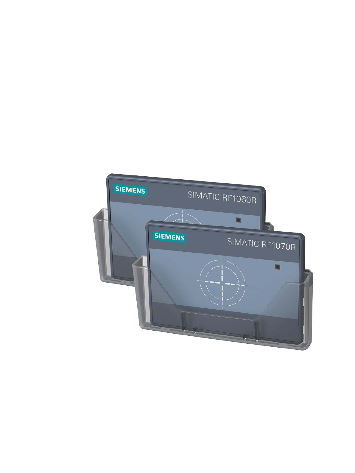
Figure 2-1 Product photo of the SIMATIC RF1060R and SIMATIC RF1070R readers
Reader-specific differences (interfaces)
The SIMATIC RF1060R/RF1070R readers are designed for connection to a Windows
computer. The connection is via a USB interface of the computer. The SIMATIC RF1070R
reader can also be connected to a Linux-based system or to a controller over the RS232
interface.
SIMATIC RF1000
Operating Instructions, 02/2019, C79000-G8976-C432-04
7

Description
SIMATIC RF1060R
SIMATIC RF1070R
Interface/Protocol
USB
USB
RS232 Freeport
demo application
demo application
200SP
2.2 Connection options and supported transponders
Interface-specific programming
On the Siemens support page "Industry Online Support
(https://support.industry.siemens.com/cs/ww/en/view/109741590
)" you will find functions for
accessing the readers in form of DLL files as well as a demo application. With operation via
the USB interface, you can implement user identification for access to your own applications
quickly and simply with the help of the DLL files. To do this, the reader reads out the serial
numbers of MIFARE, ISO 15693 and LEGIC transponders. Depending on the card type, the
serial number can be 4, 7 or 10 bytes (MIFARE / ISO 14443), 8 bytes (ISO 15693) or 4, 7 or
8 bytes (LEGIC) long.
If the SIMATIC RF1070R reader is operated via the RS232 interface, programming takes
place over the freeport protocol.
2.2 Connection options and supported transponders
Depending on the interface protocol used, the readers can be used for various applications.
The following table provides an overview of the possible uses of the readers.
Table 2- 1 Possible uses
application PM LOGON,
Connector SIMATIC Panel, PC SIMATIC Panel, PC RF170C e.g. ET
Cable Included in the scope of
delivery
PM LOGON,
Included in the scope of
delivery
STEP 7 (TIA Portal)
6GT28914UH20
6GT28912UH30
SIMATIC RF1000
8 Operating Instructions, 02/2019, C79000-G8976-C432-04

Description
SIMATIC RF1060R
SIMATIC RF1070R
Transponder families
MDS D2xx
✓ 1)
✓
MDS D4xx, D5xx ✓ --
Protocols
FeliCa
Serial number
Serial number
ISO 14443 A/B general
Serial number
Serial number
ISO 15693 general ✓ ✓
LEGIC prime
--
✓
LEGIC advant (ISO 14443 A)
Serial number
✓
LEGIC advant (ISO 15693)
Serial number
✓
Mini)
(2k, 4k, 8k)
L2, L3)
MIFARE Ultralight (C)
Serial number
Serial number
HID iClass, Inside PicoPass
Serial number
Serial number
NXP NTAG21x
Serial number
Serial number
✓
2.2 Connection options and supported transponders
Supported transponders and protocols
The following table provides an overview of the transponders and protocols supported by the
readers.
Table 2- 2 Supported transponders and protocols
MDS D1xx, D3xx, E6xx ✓ ✓
MIFARE Classic, EV1 (1k, 4k,
MIFARE DESFire, EV1/EV2
MIFARE Plus, EV1 (S, X, L1,
: Reading the serial number as well as reading and writing the user memory area
1)
Only for read-only access
✓ ✓
✓ ✓
✓ Serial number
Please note that serial numbers (UIDs) of transponders that begin with the byte "0x08" are
always newly generated by the transponder. This makes an assignment of serial numbers
and transponders impossible. Note that when the serial number is read for transponders with
combo chip (e.g. LEGIC CTC4096), only the LEGIC Prime serial number is displayed and
not the serial number of the ISO chip 14443/15693.
The reader can be addressed and controlled by functions, for example to change the status
of the reader or to communicate with a transponder. With the aid of the functions, you can for
example control the three-color reader LED. Which functions exist and how you use them is
described in this manual.
SIMATIC RF1000
Operating Instructions, 02/2019, C79000-G8976-C432-04
9

Description
2.2 Connection options and supported transponders
SIMATIC RF1000
10 Operating Instructions, 02/2019, C79000-G8976-C432-04
3
Note
Minimum/maximum thickness of the mounting wall
The thickness of the wall on which the reader is mounted must be 2
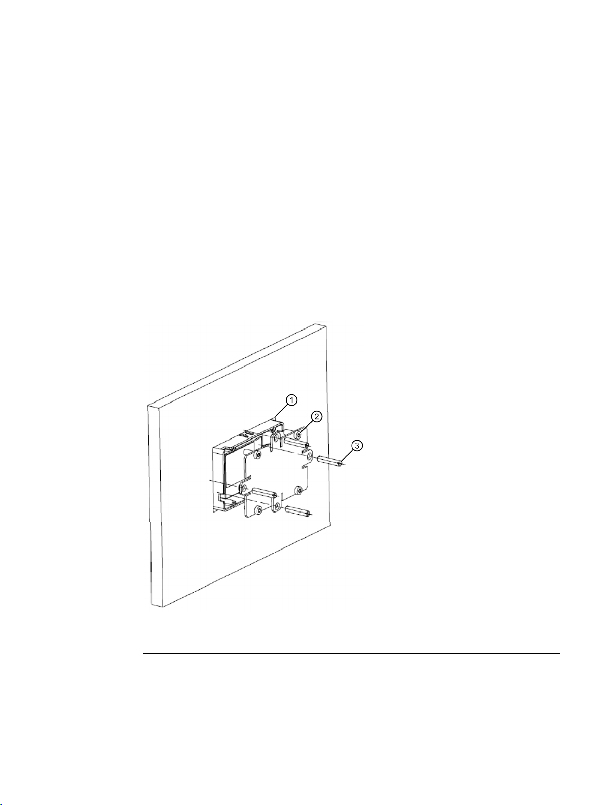
Proceed as follows to install the RF1060R/RF1070R readers:
1. Push the reader through the mounting opening intended for this purpose (76 × 48 ± 0.3
mm)
①.
Make sure that the reader locks in place so that it cannot fall out,
2. Mount the cover plate on the rear of the reader with the 4 Torx screws (max. 1.5 Nm)
3. Tighten the 4 x stud screws (max. 0.5 Nm)
4. If required, mount the optional card holder on the front of the reader.
To do this, place the card holder on the side of the reader housing and press it over the
reader front so that the card holder locks in place.
③.
②.
Figure 3-1 Mounting the RF1060R/RF1070R
SIMATIC RF1000
Operating Instructions, 02/2019, C79000-G8976-C432-04
-7 mm.
11

Installation
Note
Installation in a cabinet or metal housing
When operating the reader in an industrial environment installation in a cabinet or closed
metal housing is recommended.
NOTICE
Repair and maintenance
Do not try to repair the reader in case of a problem. Repair and maintenance work must
only be carried out by qualified personnel. Contact Siemens Support in case of repair or
maintenance problems. For more information, refer to the section "Service & Support".
SIMATIC RF1000
12 Operating Instructions, 02/2019, C79000-G8976-C432-04

4
Required tools
When using preassembled cables 6GT2891-4UH20 und 6GT2891-2UH30, you need the
following tool:
● Torx screwdriver (T8)
● Additional tools depending on the connector used
Accessories required
You need the following accessories:
● For communication via the USB interface
the connecting cable included in the scope of delivery
Connect the plug
● For communication with the RF170C communication module via the RS232 interface
the connecting cable (6GT2891-4UH20)
● For communication via the RS232 interface
The connecting cable with open ends (6GT2891-2UH30)
The procedure for connecting the reader depends on the interface over which the reader is
being operated.
Connection via USB interface
Proceed as follows to connect the SIMATIC RF1060R/RF1070R reader via the USB
interface:
1. Connect the reader to the PC or Panel using the USB cable.
Connection via RS232 interface
Proceed as follows to connect the SIMATIC RF1070R reader via the RS232 interface:
1. When using the cable 6GT2891-2UH30, you may have to install the cable connector.
You can find the connector assignment in the following table.
2. Loosen the cleat on the USB cable and remove the USB cable.
3. Connect the RS232 cable to the RS232 interface (5-pin socket).
4. Fasten the RS232 cable using the cleat.
5. Connect the reader to the communication module or the controller with the RS232 cable.
SIMATIC RF1000
Operating Instructions, 02/2019, C79000-G8976-C432-04
13
Connecting
Wire color
Assignment
red
+5 V
brown
Data line, RxD
black
GND
The table below contains the connector assignment for the connecting cable with open ends
(6GT2891-2UH30).
Table 4- 1 Connector assignment of the cable 6GT2891-2UH30
orange Data line, TxD
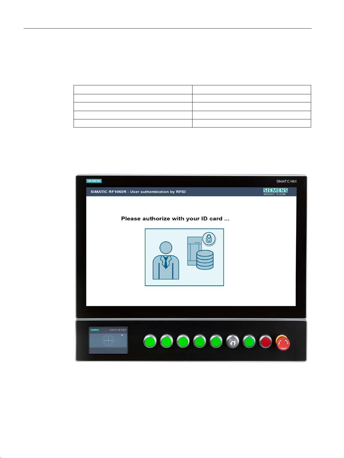
Application example
The following picture shows an example of an application of the SIMATIC RF1060R in
conjunction with a SIMATIC HMI.
SIMATIC RF1000
14 Operating Instructions, 02/2019, C79000-G8976-C432-04
Figure 4-1 Example of an application of a SIMATIC RF1060R in conjunction with a SIMATIC HMI
(e.g. 6AV7250-ODC03-0AH0) with extension unit (e.g. 6AV7674-1LA61-0AA0)

5
The procedure for installing and commissioning the reader depends on the interface over
which the reader is being operated.
Installation and commissioning via the USB interface
Proceed as follows to install and commission the SIMATIC RF1060R/RF1070R reader via
the USB interface:
1. Connect the reader to the PC or Panel using the USB cable.
Reaction: The message "A USB device was installed successfully." appears.
2. Copy the DLL drivers and the demo application on your PC using the installation file
"RF10x0R.exe".
You will find the file on the Internet on the pages of the Industry Online Support
(https://support.industry.siemens.com/cs/ww/en/view/109741590
).
3. Start the demo application by double-clicking on the file "AccessControlDemo.exe".
4. Program the reader using the demo application and the DLL functions.
You will find more information on the demo application in the section "The demo application
(Page 45)".
Installation and commissioning via the RS232 interface
Proceed as follows to install and commission the SIMATIC RF1070R reader via the RS232
interface:
1. Connect the reader to the communication module or the controller with the RS232 cable.
2. Program the PLC blocks using the freeport protocol.
You will find more information on the freeport protocol in the section "Programming via the
RS232 interface (Page 32)".
SIMATIC RF1000
Operating Instructions, 02/2019, C79000-G8976-C432-04
15

Installing and commissioning
Configuration card and VHL file
You transfer the reader configurations (e.g. memory areas, addresses, passwords, write
permissions, etc.) to the reader using the configuration card (6GT2300-0CC00-0AX0) or an
identification card (LEGIC). These configurations are saved as VHL file in the reader.
Multiple configurations (VHL files) of a configuration card can be stored on a reader.
To change the configuration of a reader with the configuration card, you must set the
"AllowConfig = true" tag when calling the function "vhl_select()" and then hold the card into
the antenna field of the reader. After you have changed the configuration, the reader
automatically restarts. After the restart you must set the "AllowConfig" tag back to "false".
The configuration card is blank upon delivery. If you prefer to receive the configuration cards
with preconfigured, customer-specific configurations, please contact Service & Support
(services.ci.industry@siemens.com).
SIMATIC RF1000
16 Operating Instructions, 02/2019, C79000-G8976-C432-04

6
Depending on the interface over which the SIMATIC RF1000 readers are being operated,
programming must take place either over the USB or the RS232 interface.
6.1 Typical applications
Below you will find typical applications for using the SIMATIC RF1060R/RF1070R readers.
The applications are shown as an example using the DLL functions. They can also be
implemented with system jobs.
Cyclic reading of serial numbers
A card that is located in the antenna field is selected with the "vhl_select" function. The serial
number of the respective card is read with the "vhl_get_snr" function.
Read and write user memory
Prerequisite for reading/writing the memory areas is that the corresponding card type and
the application are stored in the reader.
A card that is located in the antenna field is selected with the "vhl_select" function. You can
read or write to a required memory area of the respective card with the functions "vhl_read" /
"vhl_write". Because there are multiple configurations (VHL files) on the reader, the desired
configuration is selected with the "VHLFile" tag.
Autonomous reading ("Autoread")
Prerequisite for autonomous reading of the memory areas is that an "Autoread" configuration
is stored in the reader. The "Autoread" configuration can be transferred to the reader using
the configuration card.
During autonomous reading you can automatically read a desired memory area of the
respective card up to 16 bytes. The "Autoread_SetMode" function switches autonomous
reading permanently or one time on or off. During autonomous reading the reader
synchronizes the card in the antenna field with the stored configurations. If a match is found,
the corresponding memory area is read and output with "Autoread_GetMessage".
SIMATIC RF1000
Operating Instructions, 02/2019, C79000-G8976-C432-04
17

Programming
Note
Parallel operation not possible
Note that with the application, a connection can only be established to one reader at any one
time. For this reason "brp_open_usb_session" may only be called once and before it can be
called again must first be closed by the function "brp_close_session".
After a "brp_open_usb_session" the parameter "Handle" m
parameter ≠ "0", there is either an error or the function "brp_open__usb_session" was called
several times in succession.
6.2 Programming via USB interface
6.2 Programming via USB interface
You can program the reader using access functions. On the Siemens support page "Industry
Online Support (https://support.industry.siemens.com/cs/ww/en/view/109741590
obtain the file "RF10x0R.zip". It includes the DLL files ("BrpDriver_x64" and
"BrpDriver_x86"), the DLL functions as well as a demo application which demonstrates the
use of the DLL functions.
With the demo application "AccessControlDemo" you can address the reader directly from
your application via the USB interface. A precompiled DLL file for Windows systems that
provides this function is included in the package.
The DLL files provide various DLL functions for communication with the reader for integration
in your application. The reader has return values and status codes to inform you of the
reader status and execution of the functions.
You can integrate the DLL files in your application under Microsoft Windows 7/8/10 and use
them to call the described functions directly.
6.2.1 Functions of the DLL
)" you will
6.2.1.1 brp_open_usb_session
The function opens a connection to the reader via the USB interface and returns a session
key that is required for all functions and continued communication via this connection. If the
connection was successfully established, the value "BRP_OK" is returned.
Note that all the following functions can only be executed after you have established a
connection to the reader with the function "brp_open_usb_session". If this is not the case, an
error is signaled back.
Function call
int
brp_open_usb_session(
int * Handle,
DWORD ProductID
);
ust always be = "0". If the
SIMATIC RF1000
18 Operating Instructions, 02/2019, C79000-G8976-C432-04
 Loading...