

Siemens SIMATIC Rack PC 840 V2 Operating Instructions Manual
SIMATIC Industrial PC SIMATIC Rack PC 840 V2
DOCUMENTATION
Operating Instructions Edition 05/2006
Industrial PC
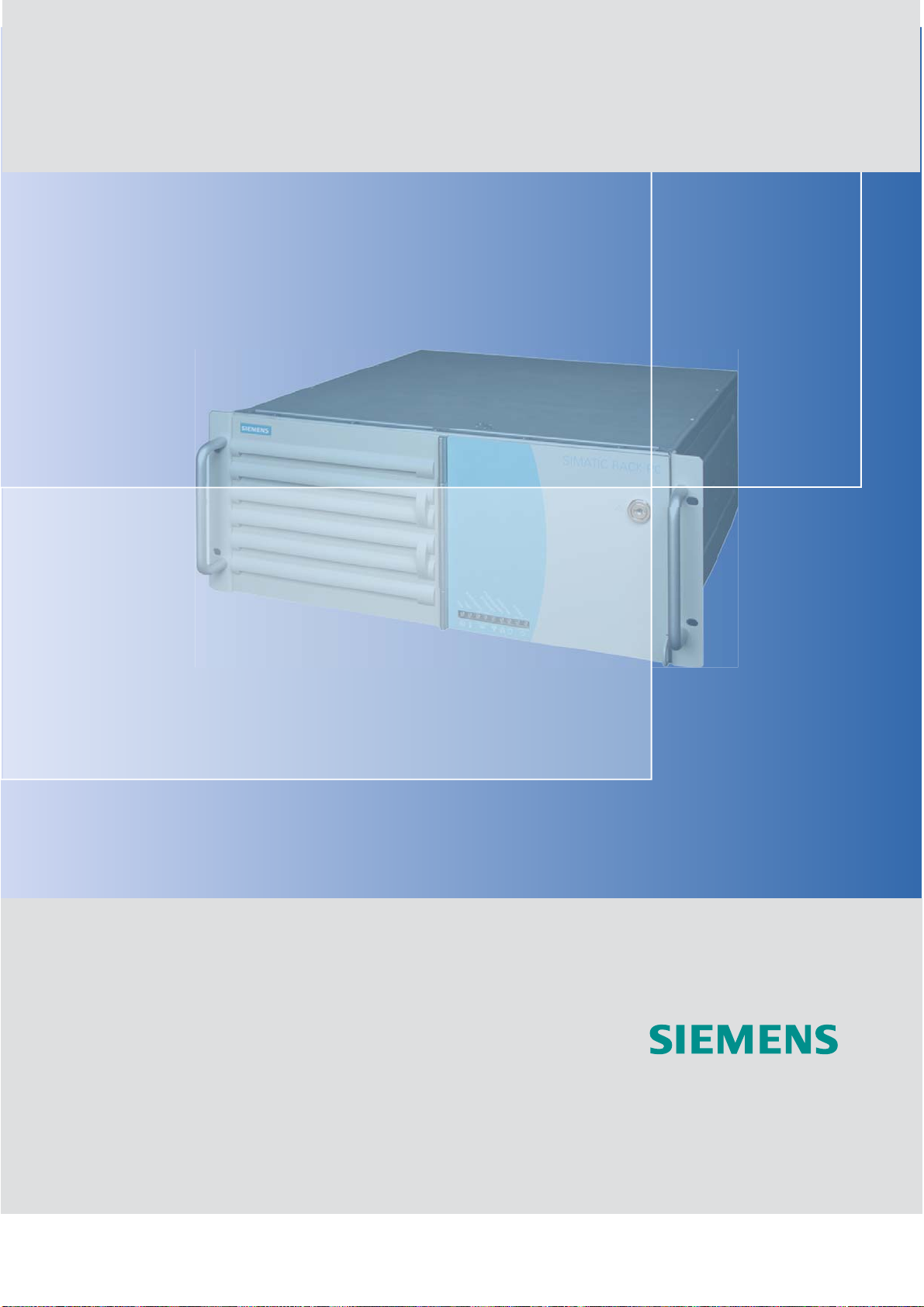
Rack PC 840 V2
simatic
DOCUMENTATION


Introduction
Safety information
Description
1
2
3
SIMATIC
Industrial PC
SIMATIC Rack PC 840 V2
Operating Instructions
Application Planning
Installation
Connecting
Commissioning
Integration
Functions
Expansions and
configuration
Maintenance and service
4
5
6
7
8
9
10
11
Edition 05/2006
A5E00248055-04
Alarm, error and system
messages
Troubleshooting
Technical data
Dimensional Drawings
Detailed descriptions
Appendix
ESD Guidelines
Abbreviations
Index
12
13
14
15
16
17
18
19

Safety Guidelines
This manual contains notices you have to observe in order to ensure your personal safety, as well as to prevent
damage to property. The notices referring to your personal safety are highlighted in the manual by a safety alert
symbol, notices referring only to property damage have no safety alert symbol. These notices shown below are
graded according to the degree of danger.
Danger
indicates that death or severe personal injury will result if proper precautions are not taken.
Warning
indicates that death or severe personal injury may result if proper precautions are not taken.
Caution
with a safety alert symbol, indicates that minor personal injury can result if proper precautions are not taken.
Caution
without a safety alert symbol, indicates that property damage can result if proper precautions are not taken.
Notice
indicates that an unintended result or situation can occur if the corresponding information is not taken into
account.
If more than one degree of danger is present, the warning notice representing the highest degree of danger will
be used. A notice warning of injury to persons with a safety alert symbol may also include a warning relating to
property damage.
Qualified Personnel
The device/system may only be set up and used in conjunction with this documentation. Commissioning and
operation of a device/system may only be performed by qualified personnel. Within the context of the safety notes
in this documentation qualified persons are defined as persons who are authorized to commission, ground and
label devices, systems and circuits in accordance with established safety practices and standards.
Prescribed Usage
Note the following:
Warning
This device may only be used for the applications described in the catalog or the technical description and only in
connection with devices or components from other manufacturers which have been approved or recommended
by Siemens. Correct, reliable operation of the product requires proper transport, storage, positioning and
assembly as well as careful operation and maintenance.
Trademarks
All names identified by ® are registered trademarks of the Siemens AG. The remaining trademarks in this
publication may be trademarks whose use by third parties for their own purposes could violate the rights of the
owner.
Disclaimer of Liability
We have reviewed the contents of this publication to ensure consistency with the hardware and software
described. Since variance cannot be precluded entirely, we cannot guarantee full consistency. However, the
information in this publication is reviewed regularly and any necessary corrections are included in subsequent
editions.
Siemens AG
Automation and Drives
Postfach 48 48
90437 NÜRNBERG
GERMANY
Order No.: A5E00248055-04
Edition 05/2006
Copyright © Siemens AG 2003 - 2006.
Technical data subject to change

Table of contents
1 Introduction............................................................................................................................................. 1-1
1.1 Guideline to the operating instructions ...................................................................................... 1-2
2 Safety information................................................................................................................................... 2-1
2.1 General safety instructions ........................................................................................................ 2-1
3 Description.............................................................................................................................................. 3-1
3.1 Overview .................................................................................................................................... 3-1
3.2 Areas of application ................................................................................................................... 3-2
3.3 Highlights ................................................................................................................................... 3-2
3.4 Function ..................................................................................................................................... 3-3
3.5 Features..................................................................................................................................... 3-3
3.6 Design........................................................................................................................................ 3-7
3.6.1 External structure....................................................................................................................... 3-7
3.6.2 Operator Controls ...................................................................................................................... 3-8
3.6.3 Connecting elements ................................................................................................................. 3-9
3.6.4 Status displays......................................................................................................................... 3-10
4 Application Planning ............................................................................................................................... 4-1
4.1 Transport.................................................................................................................................... 4-1
4.2 Unpacking and checking the delivery unit ................................................................................. 4-1
4.3 Ambient and environmental conditions...................................................................................... 4-3
5 Installation .............................................................................................................................................. 5-1
5.1 Installing the device ................................................................................................................... 5-1
6 Connecting ............................................................................................................................................. 6-1
6.1 Connecting peripherals .............................................................................................................. 6-1
6.2 Connecting the device to power................................................................................................. 6-2
6.3 Equipotential bonding ................................................................................................................ 6-4
7 Commissioning ....................................................................................................................................... 7-1
7.1 Requirements for commissioning............................................................................................... 7-1
7.2 Initial Commissioning - Initial Startup......................................................................................... 7-1
7.3 Notes on operation..................................................................................................................... 7-2
7.3.1 DVD-ROM/CD-RW .................................................................................................................... 7-2
7.3.2 DVD burner ................................................................................................................................ 7-3
7.3.3 Removable hard disks ............................................................................................................... 7-4
7.3.3.1 Change the PATA hard disk ...................................................................................................... 7-4
7.3.3.2 Change the SATA hard disk ...................................................................................................... 7-4
7.3.4 RAID system .............................................................................................................................. 7-5
7.3.5 SCSI System.............................................................................................................................. 7-6
SIMATIC Rack PC 840 V2
Operating Instructions, Edition 05/2006, A5E00248055-04
iii

Table of contents
8 Integration............................................................................................................................................... 8-1
8.1 Integration .................................................................................................................................. 8-1
9 Functions................................................................................................................................................ 9-1
9.1 Overview .................................................................................................................................... 9-1
9.2 Temperature monitoring/display ................................................................................................ 9-1
9.3 Watchdog (WD).......................................................................................................................... 9-2
9.4 Fan monitoring ........................................................................................................................... 9-2
9.5 Safecard on Motherboard (SOM)............................................................................................... 9-3
10 Expansions and configuration............................................................................................................... 10-1
10.1 Open the device ....................................................................................................................... 10-1
10.2 Memory expansion ................................................................................................................... 10-3
10.2.1 Installing memory modules ...................................................................................................... 10-3
10.3 Installing PCI / AT format PCBs ............................................................................................... 10-5
10.3.1 Notes on the modules .............................................................................................................. 10-5
10.3.2 Installing an expansion module................................................................................................ 10-5
10.4 Installing disk drives ................................................................................................................. 10-6
10.4.1 Options of installing disk drives................................................................................................ 10-6
10.4.2 Installation and removal of disk drives in the front drive bay ................................................... 10-7
10.4.3 Installation and removal of disk drives in the rear drive bay.................................................... 10-8
11 Maintenance and service...................................................................................................................... 11-1
11.1 Removing and installing hardware components ...................................................................... 11-1
11.1.1 Replacing the backup battery .................................................................................................. 11-2
11.1.2 Removing the power supply module........................................................................................ 11-4
11.1.3 Removing the bus board.......................................................................................................... 11-5
11.1.4 Removing the O ....................................................................................................................... 11-6
11.1.5 Removing the motherboard...................................................................................................... 11-7
11.1.6 Removing the equipment fan or changing the filter .................................................................11-8
11.1.7 Processor replacement ..................................................................................................
........ 11-11
11.2 Reinstalling the software ........................................................................................................ 11-14
11.2.1 General installation procedure ............................................................................................... 11-14
11.2.2 Restoring the software to factory state using the Restore CD............................................... 11-14
11.2.3 Partitioning the hard disk........................................................................................................ 11-15
11.2.3.1 Setting up the partitions under Windows 2000/XP Professional............................................ 11-15
11.2.3.2 Setting up the partitions under Windows NT.......................................................................... 11-17
11.2.4 Installing Microsoft Windows operating systems ................................................................... 11-19
11.2.4.1 Installation from the Recovery CD for Microsoft Windows NT............................................... 11-19
11.2.4.2 Installation from the Recovery CD for Microsoft Windows 2000............................................ 11-21
11.2.4.3 Installation from the Recovery CD for Microsoft Windows XP............................................... 11-23
11.2.5 Installing drivers and software ............................................................................................... 11-25
11.2.6 Installing the Raid Controller driver........................................................................................ 11-26
11.2.7 Installing the RAID Controller software .................................................................................. 11-26
11.2.8 Installing the SCSI Controller software .................................................................................. 11-27
11.2.9 Installing burner/DVD software .............................................................................................. 11-27
12 Alarm, error and system messages ...................................................................................................... 12-1
12.1 Boot error messages................................................................................................................ 12-1
12.2 BIOS POST codes ................................................................................................................... 12-3
SIMATIC Rack PC 840 V2
iv Operating Instructions, Edition 05/2006, A5E00248055-04

Table of contents
13 Troubleshooting.................................................................................................................................... 13-1
13.1 General problems .................................................................................................................... 13-1
13.2 Problems when Using Modules of Third-party Manufacturers................................................. 13-2
14 Technical data ...................................................................................................................................... 14-1
14.1 General specifications.............................................................................................................. 14-1
14.2 Power requirements of components (maximum values) ......................................................... 14-5
14.3 AC voltage supply .................................................................................................................... 14-6
14.4 Technical data of the telescopic rails ....................................................................................... 14-6
15 Dimensional Drawings.......................................................................................................................... 15-1
15.1 Dimensional Drawing of the Device ......................................................................................... 15-1
15.2 Dimensional drawing for the use of telescopic rails................................................................. 15-2
15.3 Dimensional drawings for the installation of expansion modules ............................................ 15-3
16 Detailed descriptions ............................................................................................................................ 16-1
16.1 Motherboard............................................................................................................................. 16-1
16.1.1 Structure and functions of the motherboard ............................................................................ 16-1
16.1.2 Technical features of the motherboard .................................................................................... 16-2
16.1.3 Position of the ports on the motherboard................................................................................. 16-3
16.1.4 External interfaces ................................................................................................................... 16-4
16.1.5 Internal ports .......................................................................................................................... 16-11
16.2 Bus board............................................................................................................................... 16-13
16.2.1 Layout and principle of operation........................................................................................... 16-13
16.2.2 Exclusive PCI hardware interrupt........................................................................................... 16-14
16.2.3 Pin assignment of the bus board connectors......................................................................... 16-15
16.3 Operator panel ....................................................................................................................... 16-16
16.3.1 Design .................................................................................................................................... 16-16
16.3.2 Pin assignment of the OP connectors ................................................................................... 16-16
16.4 System resources .................................................................................................................. 16-17
16.4.1 Currently Allocated System Resources ................................................................................. 16-17
16.4.2 System resources used by the BIOS/DOS ............................................................................ 16-17
16.4.2.1 I/O address allocation ............................................................................................................ 16-17
16.4.2.2 Interrupt assignments ............................................................................................................ 16-19
16.4.2.3 Memory address assignments ............................
................................................................... 16-21
16.5 BIOS Setup ............................................................................................................................ 16-22
16.5.1 Overview ................................................................................................................................ 16-22
16.5.2 Starting BIOS Setup............................................................................................................... 16-22
16.5.3 BIOS Setup menus ................................................................................................................ 16-23
16.5.4 Main menu ............................................................................................................................. 16-24
16.5.5 Advanced Menu ..................................................................................................................... 16-32
16.5.6 Security menu ........................................................................................................................ 16-38
16.5.7 Power menu........................................................................................................................... 16-40
16.5.8 Boot menu.............................................................................................................................. 16-41
16.5.9 Version menu......................................................................................................................... 16-43
16.5.10 Exit menu ............................................................................................................................... 16-44
16.5.11 Default BIOS Setup entries.................................................................................................... 16-45
SIMATIC Rack PC 840 V2
Operating Instructions, Edition 05/2006, A5E00248055-04
v

Table of contents
17 Appendix............................................................................................................................................... 17-1
17.1 Guidelines and Declarations .................................................................................................... 17-1
17.2 Certificates and Approvals ....................................................................................................... 17-2
17.3 Service and support ................................................................................................................. 17-4
17.4 Retrofitting instructions............................................................................................................. 17-6
18 ESD Guidelines .................................................................................................................................... 18-1
18.1 ESD Guidelines........................................................................................................................ 18-1
19 Abbreviations........................................................................................................................................ 19-1
Glossary ..................................................................................................................................... Glossary-1
Index................................................................................................................................................ Index-1
SIMATIC Rack PC 840 V2
vi Operating Instructions, Edition 05/2006, A5E00248055-04

Introduction
Purpose of this documentation
These operating instructions contains all the information you need for commissioning and
using the SIMATIC Rack PC 840 V2.
It is aimed at both programmers and testers who are commissioning the device themselves
and are combining the device with other units (automation systems, programming devices),
as well as service and maintenance technicians installing expansions or undertaking fault
analysis.
Scope of this documentation
This documentation applies to all supplied variants of the SIMATIC Rack PC 840 V2 and
describes the delivery status as of May 2006.
Classification in the information landscape
The operating instructions are available on the supplied "Documentation and Drivers" CD.
For supplementary instructions on how to handle the software, please refer to the
corresponding manuals.
Conventions
The abbreviation Rack PC or device is also used within this documentation for the product
name SIMATIC Rack PC 840 V2.
1
History
The following releases of the operating instructions have previously been published:
Edition Comment
12/2003 First Edition
04/2004 What is new?
• SCSI System
• DVD burner
• Assigning an exclusive interrupt
• Advanced Menu: USB Boot
• Maximum possible memory expansion changed
10/2005
05/2006
SIMATIC Rack PC 840 V2
Operating Instructions, Edition 05/2006, A5E00248055-04
• PCI SATA RAID Controller, in combination with a SATA hard drive
• SATA swap frames (in connection with SATA RAID controllers)
• Failure recovery
• Capacity of the SATA hard drives
• Change to the heat sink mounting
• Power supply with autorange supply voltage input
1-1

Introduction
1.1 Guideline to the operating instructions
1.1 1.1 Guideline to the operating instructions
Contents format Contents
Contents Organization of the documentation, including the index of pages and chapters
Introduction Purpose, layout and description of the important topics.
Safety information Refers to all the valid safety-related aspects which are derived from statutory regulations
and should be adhered to when installing, commissioning and operating the
product/system.
Description Fields of application, the features and the structure of the product/system
Application Planning Aspects of storage, transport, environmental and EMC conditions to be considered in the
preparatory stage
Installation Product installation options and installation instructions
Connecting Options of connecting the product and connection instructions
Commissioning Commissioning the product/system.
Integration Options of integrating the product into existing or planned system environments/networks
Functions Monitoring and display functions
Expansions / Configuration Procedure for expansion devices (memory, modules, drives)
Maintenance and service Replacement of hardware components, restoring and setup of the operating system,
installation of drivers and software
Troubleshooting Problems, cause, remedy
Technical Data General specifications in compliance with relevant standards and current/voltage values
Dimensional drawings Dimensions of the device and of modules
Detailed descriptions Structure, function and features of the vital components, allocation of system resources and
use of the BIOS Setup
Appendix Guidelines and certifications, service and support, notes on retrofitting
ESD Guidelines General ESD guidelines.
SIMATIC Rack PC 840 V2
1-2 Operating Instructions, Edition 05/2006, A5E00248055-04
Safety information
2.1 2.1 General safety instructions
Caution
Please observe the safety instructions on the back of the cover sheet of this documentation.
You should not expand your device unless you have read the relevant safety instructions.
This device is compliant with the relevant safety measures to IEC, EN, VDE, UL, and CSA. If
you have questions about the validity of the installation in the planned environment, please
contact your service representative.
Repairs
Only authorized personnel are permitted to repair the device.
2
Warning
Unauthorized opening and improper repairs can cause considerable damage to property or
danger for the user.
System expansions
Only install system expansion devices designed for this device. The installation of other
expansions can damage the system and violate the radio-interference suppression
regulations. Contact your technical support team or where you purchased your PC to find out
which system expansion devices may safely be installed.
Caution
If you install or exchange system expansions and damage your device, the warranty
becomes void.
SIMATIC Rack PC 840 V2
Operating Instructions, Edition 05/2006, A5E00248055-04
2-1
Safety information
2.1 General safety instructions
Battery
This device is equipped with a Lithium battery. Batteries may only be replaced by qualified
personnel.
Caution
There is the risk of an explosion if the battery is not replaced as directed. Replace only with
the same type or with an equivalent type recommended by the manufacturer. Dispose of
used batteries in accordance with local regulations.
Warning
Risk of explosion and release of harmful substances!
Therefore, do not throw Lithium batteries into an open fire, do not solder or open the cell
body, do not short-circuit or reverse polarity, do not heat up above 100° C, dispose of in
accordance with regulations and protect against direct exposure to sunlight, moisture and
condensation.
ESD guidelines
Modules containing electrostatic sensitive devices (ESDs) can be identified by the following
label:
Strictly follow the guidelines mentioned below when handling modules which are sensitive to
ESD:
• Always discharge your body´s static electricity before handling modules which are
sensitive to ESD (for example, by touching a grounded object).
• All devices and tools must be free of static charge.
• Always pull the mains connector and disconnect the battery before you install or remove
modules which are sensitive to ESD.
• Handle modules fitted with ESDs by their edges only.
• Do not touch any wiring posts or conductors on modules containing ESDs.
SIMATIC Rack PC 840 V2
2-2 Operating Instructions, Edition 05/2006, A5E00248055-04
Description
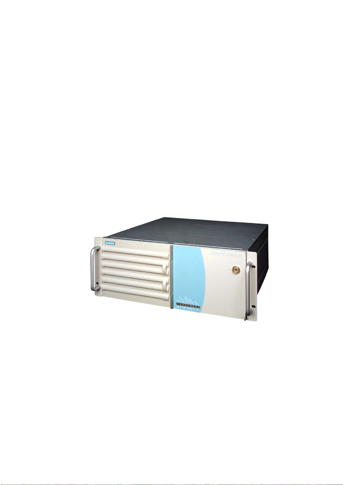
3.1 3.1 Overview
SIMATIC Rack PC 840 V2 is an industrial PC in 19" rack format (4HU) with excellent
industrial functionality.
• High expandability
• Rugged
• High product continuity
3
Figure 3-1 Rack PC 840 V2
SIMATIC Rack PC 840 V2
Operating Instructions, Edition 05/2006, A5E00248055-04
3-1

Description
3.2 Areas of application
3.2 3.2 Areas of application
SIMATIC Rack PC 840 V2 offers a high-performance and highly flexible 19" rack PC
platform to machine, plant and control cabinet engineering for use in a machine-oriented
industrial environment:
• Measuring, control and closed loop control of process and machine data, for example,
ultrasonic measurement technology in the automotive industry, gear test benches
• Visualization of production sequences, such as in paper processing or conveying
technology
• Image processing and editing in the course of quality control, e.g. inspection of the
surface of optical lenses
• Data logging and data management, e.g. on motor test benches in the automotive
industry, tire manufacturing
The SIMATIC Rack PC 840 V2 is certified to CE for industrial applications.
3.3 3.3 Highlights
Highlights of the SIMATIC Rack PC 840 V2
Highly compatible with industrial standards:
• High operational vibration and shock resistance
• High operational temperature range
• High service friendliness
• Distinct diagnostic features
High industrial functionality:
• Integrated PROFIBUS DP / MPI interface (optional)
• ISA and PCI slots
• High flexibility and expandability of components
High investment security:
• High continuity of the component / design
• Guaranteed spare parts availability for at least 5 years
High system availability:
• SIMATIC PC DiagMonitor – PC diagnostics / message software via OPC/SNMP/LAN
• SIMATIC PC/PG Image Creator – data imaging software
• RAID1 – redundant data saving on two hard disks protects against data loss
SIMATIC Rack PC 840 V2
3-2 Operating Instructions, Edition 05/2006, A5E00248055-04

Description
3.4 Function
3.4 3.4 Function
• Integrated and configurable monitoring functions (program execution (watchdog), internal
enclosure temperature, fan speed)
• Enhanced diagnostic / messaging via Ethernet, E-mail, SMS, and for direct input in
SIMATIC software via OPC (optional via SIMATIC PC DiagMonitor):
– Operating hours counter
– Hard disk status
– System status (heartbeat)
– Automatic logging of all messages by means of log file
– Options of central monitoring of networked SIMATIC PCs
• RAID1 for automatic data mirroring on two hard disks
3.5 3.5 Features
General features
Design
Enclosure
Drive bays
Slots for expansion cards
Video Pro Savage 8 AGP 4x
Interfaces
PROFIBUS/MPI (12 Mbps)
• 19” rack, 4 HE
• Robust installation enclosure, all metal
• Prepared for mounting telescopic rails
• Horizontal installation is possible
• Lockable front cover as access protection
• Dust protection by means of overpressure ventilation
using bearing seated front fan through filter
• Case cover can be opened and front fan can be
replaced without special tools
• Card retainer for reliable operation of PC modules under
vibration and shock conditions
• Front: 3 x 5.25" and 2 x 3.5"
• Internal: 2 x 3.5" (in the optional vibration-damping drive
bracket)
• 5x PCI long
• 2x PCI/ISA (shared) long
• 3x ISA long
max. 10 modules simultaneously
8 to 32 MB used in RAM
CRT:
-up to 1280x1024 at 100 Hz / 32-bit color resolution
-up to 1600 x1200 at 60 Hz / 16-bit color resolution
12 Mbps (isolated potential, compatible to CP 5611);
optional
SIMATIC Rack PC 840 V2
Operating Instructions, Edition 05/2006, A5E00248055-04
3-3
Description
3.5 Features
General features
Ethernet 10/100 Mbps (RJ45)
USB 1 x front, 2 x back; (high-current)
Serial COM1 (V.24), COM2 (V.24)
Parallel LPT1
VGA 1 x
Keyboard PS/2
Mouse PS/2
Power supply 120/230 V AC, Autorange; with buffering for short power
outages in accordance with NAMUR: max. 20 ms at
0.85 nominal voltage
Monitoring functions
Temperature
Fan Speed monitoring
Watchdog
Status LEDs
• Overshoot/undershoot of permissible operating
temperature
• Messages can be evaluated by the application program.
• Monitoring of program execution
• Monitoring time can be parameterized in software
• Restart can be parameterized in the event of a fault
• Messages can be evaluated by the application program.
• POWER (internal power supply unit, PC switched On)
• HARDDISK (access to hard disk)
• MPI (PROFIBUS/MPI interface)
• WATCHDOG (Watchdog function/error display)
• TEMP (temperature status)
• ETHERNET (Ethernet status, "heartbeat")
• FAN (Speed monitoring
Standard versions
Processor Intel Pentium 4 2.4 GHz, 533 FSB
Main memory expansion DDR266 SDRAM (PC2100)
3 slots, up to 2 GB
Hard disk
Floppy drive 1,44 MB, installation in front drive bay
Hard disk drives 40 GB EIDE, 3.5"
Operating system without
SIMATIC Rack PC 840 V2
3-4 Operating Instructions, Edition 05/2006, A5E00248055-04

Description
3.5 Features
Optional accessories
Processor
Main memory expansion Up to 2 GB
PROFIBUS/MPI 12 Mbps (isolated potential, compatible to CP 5611)
Hard disk
DVD-ROM Read:
DVD ROM/CD RW Read:
DVD burner Read:
• Intel Celeron 2.0 GHz, 400 FSB
• Intel Pentium 4 Mobile 2.2 GHz, 400 FSB
• Intel Pentium 4 2.8 GHz, 533 FSB
DVD-ROM
Single layer 16x
Dual Layer 8x
DVD-Video 4x
DVD+R/RW, DVD-R/RW 8x
DVD-RAM 2x
CD-ROM, CD-R 32x
DAE 48x
CD-DA, Video CD 20x
CD-RW 20x
DVD-ROM
Single Layer 16x,
Dual Layer 8x
DVD-R/-RW/+R/+RW 8x
DVD-Video 16x
CD-ROM 52x
CD-R/RW 40x
DAE 48x
Write:
CD-R 52x, CD-RW 40x
(alternative DVD-ROM)
DVD-ROM
Single Layer16x,
Dual Layer 12x
DVD-R/+R
Single Layer16x
Dual Layer 7x
DVD-RW/+RW 13x
DVD-Video
Single Layer 16x
Dual Layer 12x
CD-ROM/CD-R Read 48x
CD-RW Read 40x
DAE Read 40x
Write:
DVD+R 16x
DVD+RW 8x
DVD-R 16x
DVD-RW 6x
DVD+R9 (DL) 8x
DVD-R DL 8x
CD-R 48x
CD-RW 32x
SIMATIC Rack PC 840 V2
Operating Instructions, Edition 05/2006, A5E00248055-04
3-5

Description
3.5 Features
Optional accessories
Hard disk drives
Operating system Preinstalled / supplied on Restore DVD
Installation in the rear drive slot
• 40 GB EIDE, 3.5"
• 80 GB EIDE, 3.5"
• 2 x 80 GB EIDE; 3.5"
• 36 GB SCSI
• 72 GB SCSI (from 06/2006)
• RAID1, 2x 80 GB EIDE; 3.5" (mirroring) in combination
with Windows NT
• SATA-RAID1, 120 GB SATA (from 06/2006); 3.5"
(mirrored drives). In combination with all configurations
other than Windows NT
Installation in the front drive bay
• 40 GB EIDE; 3.5", in swap frame
• 80 GB EIDE; 3.5"
• 80 GB EIDE; 3.5", in swap frame
• 2 x 80 GB EIDE; 3.5"
• 2 x 80 GB EIDE; 3.5", in swap frame
• RAID1, 2x 80 GB EIDE; 3.5" (mirrored disks)
In combination with Windows NT
• RAID1, 2 x 80 GB EIDE; 3.5" (mirrored drives) in swap
frame. In combination with Windows NT
• SATA-RAID1, 120 GB SATA (from 06/2006); 3.5"
(mirrored drives). In combination with all configurations
other than Windows NT
• SATA-RAID1, 120 GB SATA (from 06/2006); 3.5"
(mirrored drives) in swap frames. In combination with all
configurations other than Windows NT
• MS-DOS 6.22 English
• Windows NT German/English
Not in combination with SATA RAID1
• Windows 2000 Professional MUI*
• Windows XP Professional MUI*
*MUI: Multi language User Interface; 5 languages (German,
English, French, Spanish, Italian)
Optional expansions
SIMATIC PC
DiagMonitor SW
SIMATIC PC
Image Creator SW
SIMATIC Rack PC 840 V2
3-6 Operating Instructions, Edition 05/2006, A5E00248055-04
Software tool for monitoring local and remote SIMATIC
PCs:
• Watchdog
• Temperature
• Fan speed
• Hard disk monitoring (SMART)
• System / Ethernet monitoring (Heart Beat)
Software tool for saving data locally
Description
3.6 Design
3.6 3.6 Design
3.6.1 External structure
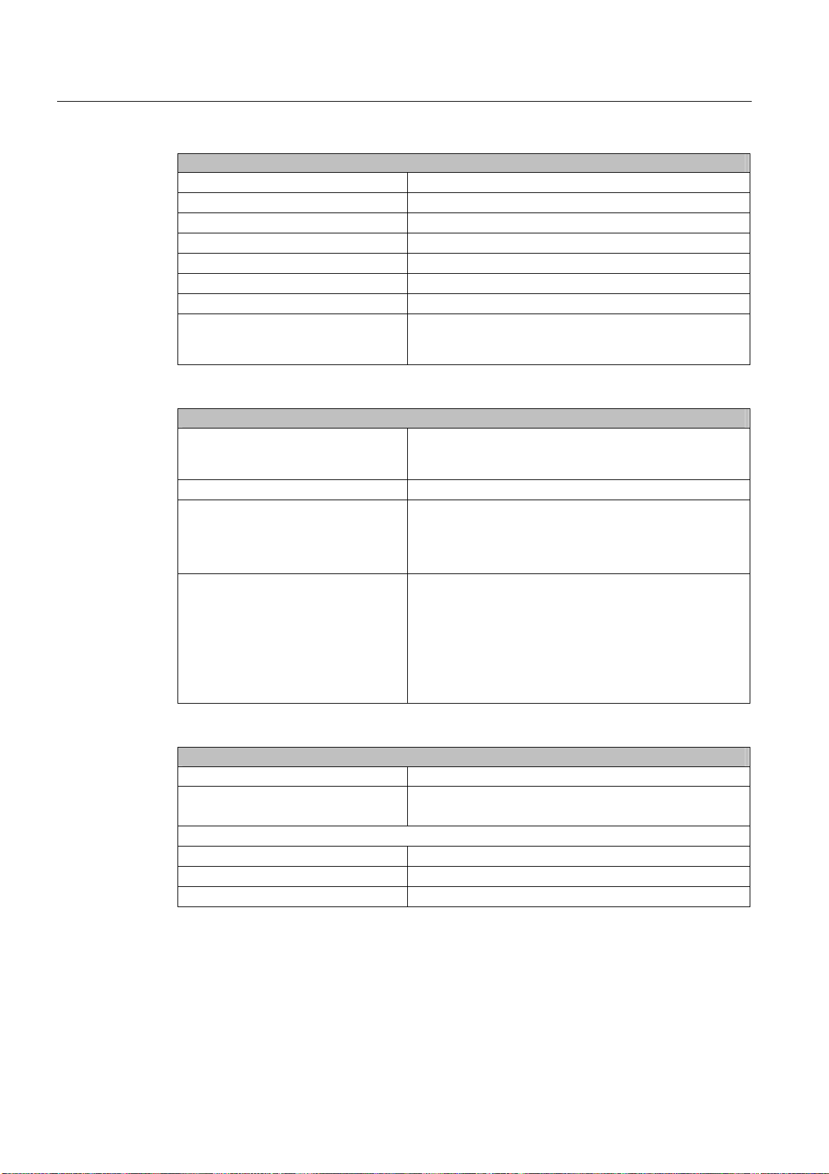
Front view of the device Pos Description
(1) Front door with lock,
provides protection against
dirt and unauthorized
access. Keep the door
closed during normal
operation.
(2) USB port
(3) Reset button
(4) Status displays
(5) On/off button
(6) Option of installing a floppy
disk drive
(7) Option for installing
DVD-ROM, DVD-ROM/
CD-RW drives, DVD burners
and removable racks for
hard disks
(8) Front panel with openings
for ventilating the device
(filter mat and fan are
positioned behind the front
panel). Check the filter mat
regularly for soiling and, if
appropriate, replace it.
Rear view of the device Pos Description
(1) Fan / power supply unit
(2) Power supply connection
(3) Rating plate (may also be
mounted on the inside of the
front panel door)
(4) Drive cooling fan at the rear
(optional)
(5) Connecting elements
(6) Expansion slots
SIMATIC Rack PC 840 V2
Operating Instructions, Edition 05/2006, A5E00248055-04
3-7
Description
3.6 Design
3.6.2 Operator Controls
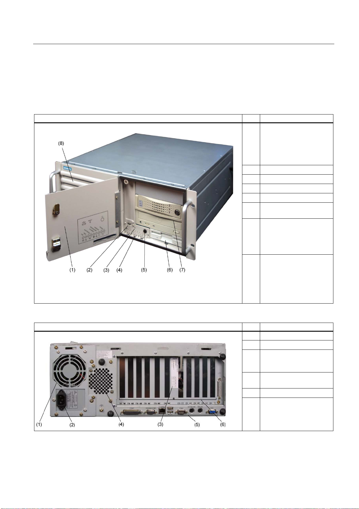
Operator controls On/Off button and Reset button Pos Description
(1) Reset button
The reset button can be actuated with a
pin or an opened up paper clip, for
example. The button signal triggers a
hardware reset. The PC performs a
restart (cold start).
(2) On/off button
For switching the device on or off
Caution
Data may be lost when the PC performs a hardware reset.
Warning
The on/off button signal does not switch off power to the PC!
SIMATIC Rack PC 840 V2
3-8 Operating Instructions, Edition 05/2006, A5E00248055-04

Description
3.6 Design
3.6.3 Connecting elements
Interfaces
Layout of the interfaces on the rear of the device
Pos Designation Description
(1) COM 1 Serial port 1 (V.24), 25-pin sub D socket
(2) PROFIBUS/MPI MPI interface (RS485, electrically isolated), optional 9-pin sub D socket
(3) ETHERNET RJ 45 Ethernet connection 10/100 Mbps
(4) USB USB-device connectors. Bottom USB port 1, top USB port 2.
(5) COM2 Serial port (V.24), 9-pin sub D plug
(6) KEYBOARD Connection for a PS/2 keyboard
(7) MOUSE Connection for a PS/2 mouse
(8) VGA Connection for VGA monitor
(9) LPT1 Parallel interface, 25-pin
Power supply
Position of the IEC power connector Description
IEC power connector for the AC power supply to
the device. The allowable supply voltage is
120 V AC or 230 V AC
SIMATIC Rack PC 840 V2
Operating Instructions, Edition 05/2006, A5E00248055-04
3-9
Description
3.6 Design
3.6.4 Status displays
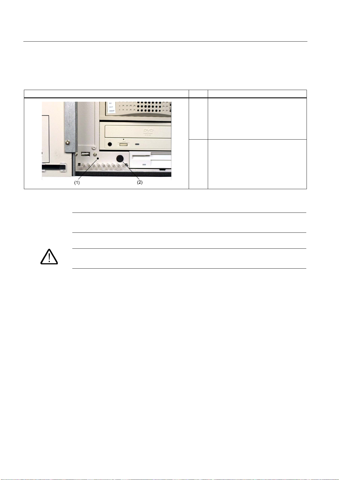
Status displays
Display Meaning LEDs Description
FAN CPU fan status (available only
with active SOM or DiagMonitor
software)
TEMP Internal temperature monitoring OFF
WATCHDOG WATCHDOG Status display OFF
ETHERNET ETHERNET status display OFF
PROFIBUS /
MPI
HARDDISK Display for hard disk access OFF
POWER PC status display OFF
Display of the communication
status to the S7 or PROFIBUS
OFF
RED
RED
GREEN
RED
GREEN
OFF
GREEN
GREEN
YELLOW
GREEN
- Fan speed OK
- CPU not started
(see error dialog)
- Fan speed too low
(see error dialog)
- Internal temperature OK
- Internal temperature is critical
(see error dialog)
- WATCHDOG disabled
- WATCHDOG monitoring enabled
- Time-out (see error dialog)
- not connected
- no data transfer
- data transfer
- not connected
- no data transfer
- data transfer
- No access
- Access
- Disconnected from mains
- Standby (hibernate)
- PC in operation
SIMATIC Rack PC 840 V2
3-10 Operating Instructions, Edition 05/2006, A5E00248055-04

Application Planning
4.1 4.1 Transport
Despite the device's rugged design, its internal components are sensitive to severe
vibrations or shock. You must therefore protect the PC from severe mechanical stress when
transporting it.
You should always use the original packaging for shipping and transporting the device.
Caution
Risk of damage to the device!
When transporting the PC in cold weather, it may be submitted to extreme variations in
temperature. In this situation, ensure that no moisture (condensation) develops on or inside
the device.
If condensation develops, wait at least 12 hours before switching on the device.
4
4.2 4.2 Unpacking and checking the delivery unit
Unpacking the device
Note the following points when you unpack the unit
• It is advisable not to dispose of the original packing material. Keep it in case you have to
transport the unit again.
• Please keep the documentation in a safe place. It is required for initial commissioning and
is part of the device.
• Check the delivery unit for any visible transport damage.
• Verify that the shipment contains the complete unit and your separately ordered
accessories. Please inform your local dealer of any disagreements or transport damages.
SIMATIC Rack PC 840 V2
Operating Instructions, Edition 05/2006, A5E00248055-04
4-1
Application Planning
4.2 Unpacking and checking the delivery unit
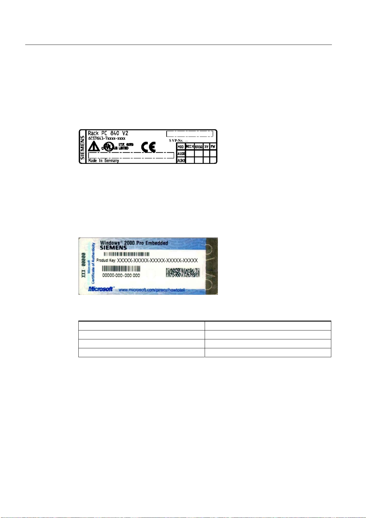
Noting the device identification data
The device can be identified uniquely with the help of these numbers in case of repairs or
theft.
Enter the following data in the table below:
• Serial number: The serial number (S VP) is located on the type plate either on the rear
panel of the device or on the inside of the front door.
Figure 4-1 Type plate
• Order number of the device
• Ethernet address: You find the Ethernet address of the device in your BIOS Setup
(F2 function key) , under Info > (F1 function key) > LAN Address.
• Microsoft Windows "Product Key" from the "Certificate of Authenticity" (COA). The COA
label is found on the inside of the front door.
You may need the Product Key in case you reinstall the operating system.
Figure 4-2 COA label
Serial number S VP ...
Order No. 6ES ...
Microsoft Windows Product Key
Ethernet address
SIMATIC Rack PC 840 V2
4-2 Operating Instructions, Edition 05/2006, A5E00248055-04

Application Planning
4.3 Ambient and environmental conditions
4.3 4.3 Ambient and environmental conditions
When you plan your project, you should make allowances for:
• Note the climatic and mechanical environmental conditions specified in the specifications
provided by your operating manual.
• Avoid extreme ambient conditions as far as possible. Protect your PC from dust,
moisture, and heat.
• Keep the PC out of direct sunlight.
• Mount the PC as safely as possible to prevent danger (for example, of falling over).
• The device satisfies protection class IP 41 on the front panel. In areas where splashing is
likely, ensure that the device's installation opening is splash-proofed.
• The area around the ventilation slots must be at least 50 mm, in order that the PC is
sufficiently ventilated.
• Do not cover the device's vent slots.
• The device fulfils the requirements for a fire enclosure according to EN 60950-1. It can be
installed without additional fire protection.
Warning
If these requirements are not adhered to when installing the system, the approvals
according to UL 60950-1, EN 60950-1 are voided and there will is a danger of
overheating and a hazard for personnel!
SIMATIC Rack PC 840 V2
Operating Instructions, Edition 05/2006, A5E00248055-04
4-3

Application Planning
4.3 Ambient and environmental conditions
SIMATIC Rack PC 840 V2
4-4 Operating Instructions, Edition 05/2006, A5E00248055-04

Installation
5.1 5.1 Installing the device
Possible areas of installation
The device may be installed in control desks, switching cabinets and 19`` rack systems.
Possible mounting methods
Options of mounting the device
• Mounting with cabinet brackets
• Installing with telescopic rails
When telescopic rails are used, the devices can be completely removed from the cabinet
or rack.
Refer to the sections "Technical data of the telescopic rails" and "Dimensional drawing for
the use of telescopic rails" for more detailed information.
5
Figure 5-1 Position of the mounting holes for angle brackets or telescopic rails
Caution
The mounting screws of the telescopic rails may not protrude more than 5 mm into the
enclosure.
Caution
Danger of bodily harm!
It is not permitted to mount the device only on the 19" brackets of the front panel.
SIMATIC Rack PC 840 V2
Operating Instructions, Edition 05/2006, A5E00248055-04
5-1

Installation
5.1 Installing the device
Caution
Remove the bonded stands when mounting the device on telescopic rails. Restricted
technical specifications for drives in the front drive bay apply for this type of installation.
For details, refer to the technical data or retrofitting instructions.
SIMATIC Rack PC 840 V2
5-2 Operating Instructions, Edition 05/2006, A5E00248055-04

Connecting
6.1 6.1 Connecting peripherals
Note before connecting
Notice
Connect only I/O modules approved for industrial applications to EN 61000-6-2:2001.
Note
Hot-plug I/O modules (USB) may be connected while the PC is in operation.
6
Caution
I/O devices not capable of hot-plugging may only be connected after the device has been
disconnected from the power supply.
Caution
Strictly adhere to the specifications for I/O modules.
SIMATIC Rack PC 840 V2
Operating Instructions, Edition 05/2006, A5E00248055-04
6-1

Connecting
6.2 Connecting the device to power
6.2 6.2 Connecting the device to power
To be noted before you connect the device
Note
The autorange-power-supply is designed for 120/230/240 V AC power networks. The setting
of the voltage range takes place automatically.
Warning
Do not connect or disconnect power and data cables during thunderstorms.
Warning
The device is designed for operation on grounded power supply networks (TN systems to
VDE 0100, part 300, or IEC 60364-3).
Operation on ungrounded or impedance-grounded power networks (IT networks) is
prohibited.
Warning
The permitted nominal voltage of the device must conform with local mains voltage.
Caution
The mains connector must be disconnected to fully isolate the device from mains. Ensure
easy access to this area.
A master mains disconnect switch must be installed if the device is mounted in a switch
cabinet. Always ensure free and easy access to the power inlet on the device or that the
safety power outlet of the building installation is freely accessible and located close to the
device.
SIMATIC Rack PC 840 V2
6-2 Operating Instructions, Edition 05/2006, A5E00248055-04
 Loading...