

Siemens SIMATIC PS307, 6ES7307-1EA01-0AA0, 6ES7307-1BA01-0AA0, 6ES7307-1KA02-0AA0 Operating Instructions Manual
© Siemens AG Österreich, AT-1210 Vienna, Austria. All rights reserved.
A5E36063733, 07.2016
1
SIMATIC PS307
6ES7307-1BA01-0AA0 (24 V/2 A)
6ES7307-1EA01-0AA0 (24 V/5 A)
6ES7307-1KA02-0AA0 (24 V/10 A)
Betriebsanleitung (kompakt)
Operating Instructions (compact)
Instrucciones de servicio (resumidas)
操作说明 (精简版)
Notice de service (compacte)
Istruzioni operative (descrizione sintetica)
Руководство по эксплуатации (компактное)
https://support.industry.siemens.com
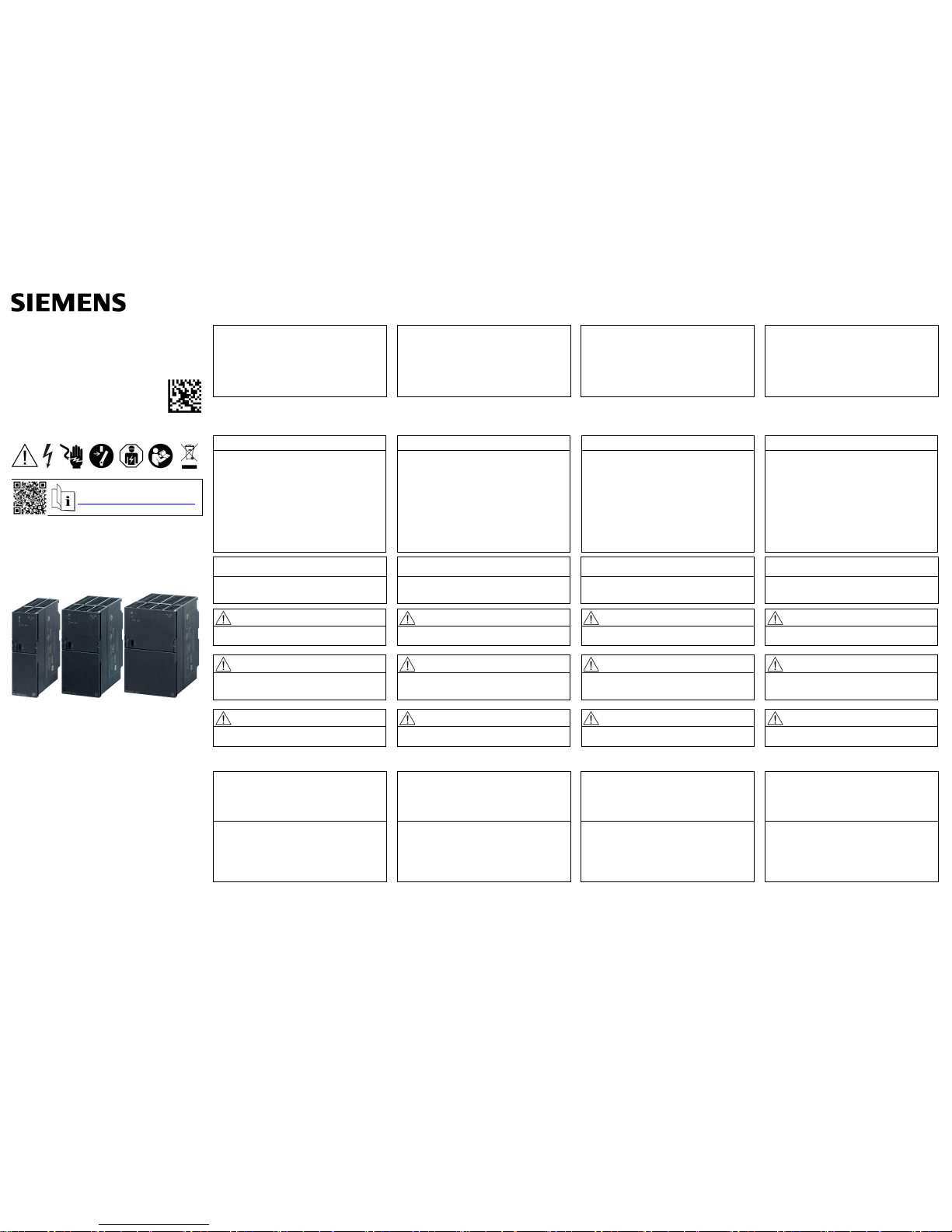
Bild
1: Ansicht Gerät
Figure
1: View of the device
Figura
1: Vista del aparato
图
1: 设备外观
Figure
1: Vue de l'appareil
Figura
1: Vista dell'apparec chio
Рисунок
1: Внешний вид устройства
DEUTSCH
Beschreibung
Die SIMATIC Stromversorgungen s ind Einbaugeräte,
Schutzart IP20, Schutzklasse I.
Primär getaktete Stromversor gungen zum Anschluss
an 1-phasiges Wechselstromnetz 120/230 V,
50 - 60 Hz; Ausgangsspannung +24 V DC,
potenzialfrei, kurzschluss - und leerlauffest.
Siehe
Bild 1 Ansicht Gerät (Seite 1)
Sicherheitshinweise
ACHTUNG
Der einwandfreie und sichere Betri eb dieses
Gerätes/Systems setzt sachgemäß en Transport,
sachgemäße Lagerung, Aufstellung u nd Montage
sowie sorgfältige Bedienung und I nstandhaltung
voraus.
Dieses Gerät/System darf nur unter Beachtung der
Instruktionen und Warnhinweise der zugehörigen
technischen Dokumentation einger ichtet und betrieben
werden.
Nur qualifiziertes Personal dar f das Gerät/System
installieren und in Betrieb setz en.
Das Gerät erfüllt die ATEX Richtli nie 2014/34/EU;
EN 60079-0; EN 60079-15
Geeignet für Ex-Anwendungen in CLASS I,
DIVISION 2, GROUPS A, B, C und D, oder in nicht-
explosiver Umgebung.
WARNUNG
SCHALTERBETÄTIGUNG NUR IN NICHTEXPLOSIVER UMGEBUNG DURCHFÜHREN!
WARNUNG
EXPLOSIONSRISIKO – DURCH AUSTAUSCH VON
KOMPONENTEN KANN DIE EIGNUNG FÜR CLASS I,
DIVISION 2 BEEINTRÄCHTIGT WERDEN
WARNUNG
DURCH EINFLUSS VON CHEMIKALIEN KANN DIE
DICHTHEIT VON RELAIS REDUZIERT WERDEN.
Montage
Montage auf S7-300-Profilschi ene.
Das Gerät ist so auf der Schiene zu vers chrauben,
dass die Klemmen unten sind.
Unterhalb und oberhalb des Gerätes sind mindestens
Freiräume von 40 mm einzuhalten.
Bei Installation des Gerätes i n explosionsgefährdeter
Umgebung (II 3G Ex nA nC IIC T4 Gc (2 A) /
II 3G Ex nA nC IIC T3 Gc (5 A, 10 A)) ist dieses in
einen Verteilerkasten mit Schut zart IP54 oder höher
einzubauen. Dieser Verteilerk asten muss den
Anforderungen der EN 60079-15 entspr echen und darf
nur mit einem Werkzeug zu öffnen sein.
Siehe
Bild 2 Aufbau (Seite 2)
ENGLISH
Description
SIMATIC power supplies are built -in units, degree of
protection IP20, protection c lass I.
Primary switched-mode power suppl ies for connection
to a 1-phase AC line supply 120/230 V, 50 - 60 Hz ;
output voltage +24 V DC, isolated, s hort-circuit proof
and idling proof.
See
Figure 1 View of the device (Page 1)
Safety notes
NOTICE
Appropriate transport, proper s torage, mounting, and
installation, as well as careful operation and service,
are essential for the error-free, safe and reliable
operation of the device/system.
Setup and operation of this device/ system are
permitted only if the instructi ons and warnings of the
associated technical document ation are carefully
observed.
Only qualified personnel are allo wed to install the
device/system and set it into operat ion.
The device complies with ATEX direc tive 2014/34/EU;
EN 60079-0; EN 60079-15
Suitable for Ex applications i n CLASS I, DIVISION 2,
GROUPS A, B, C and D - or in non-hazardous zones.
WARNING
ACTUATE SWITCHES IN NON-HAZARDOUS AREAS
ONLY!
WARNING
EXPLOSION HAZARD – SUBSTITUTION OF
COMPONENTS MAY IMPAIR SUITABILITY FOR
CLASS I, DIVISION 2
WARNING
CHEMICALS CAN MEAN THAT RELAYS ARE NO
LONGER PERFECTLY SEALED.
Assembling
Mounting on S7-300 mounting rails.
The device should be mounted on the rail so that the
terminals are at the bottom.
Above and below the device, clearanc es of at least
40 mm must be maintained.
If the device is to be used in a hazardous z one
(II 3G Ex nA nC IIC T4 Gc (2 A) /
II 3G Ex nA nC IIC T3 Gc (5 A, 10 A)) it must be
installed in a distribution box wi th degree of protection
IP54 or higher. This enclosure mus t comply with the
requirements of EN 60079-15 and may only be opened
by the use of a tool.
See
Figure 2 Design (Page 2)
ESPAÑOL
Descripción
Las fuentes de alimentación SIMATI C son modelos
empotrables, con grado de protecc ión IP20, clase de
protección I.
Fuentes de alimentación conmutadas en primario para
la conexión a una red de corriente alt erna monofásica
de 120/230 V, 50 - 60 Hz; tensión de sali da de
+24 V DC, con aislamiento galvánico, resistente a
cortocircuito y marcha en vacío.
Ver
Figura 1 Vista del aparato (Página 1)
Consignas de seguridad
ATENCIÓN
El funcionamiento correcto y seguro de es te
aparato/sistema presupone un trans porte, un
almacenamiento, una instalación y un montaje
conformes a las prácticas de la buena ing eniería, así
como un manejo y un mantenimiento rigur osos.
Este aparato/sistema debe ajustar se y utilizarse
únicamente teniendo en cuenta las instrucciones y
advertencias de la documentación téc nica
correspondiente.
La instalación y puesta en marcha del apar ato/sistema
debe encomendarse exclusivament e a personal
cualificado.
El aparato cumple la directiva ATEX 20 14/34/UE;
EN 60079-0; EN 60079-15.
Adecuado para aplicaciones Ex de CLAS S I,
DIVISION 2, GROUPS A, B, C y D, o bien para
entornos no explosivos.
ADVERTENCIA
¡ACCIONAR INTERRUPTORES ÚNICAMENTE EN
ENTORNOS NO EXPLOSIVOS!
ADVERTENCIA
PELIGRO DE EXPLOSIÓN: AL SUSTITUIR
COMPONENTES PUEDE VERSE AFECTADA LA
APTITUD PARA CLASS I, DIVISION 2.
ADVERTENCIA
LAS SUSTANCIAS QUÍMICAS PUEDEN REDUCIR LA
ESTANQUEIDAD DE LOS RELÉS.
Montaje
Montaje en perfil soporte S7-300.
El aparato debe atornillarse en el soporte de forma que
los bornes queden abajo.
Por debajo y por encima del aparato debe d ejarse un
espacio libre de al menos 40 mm.
Si se va a instalar el aparato en una atmósf era
potencialmente explosiva (II 3G Ex nA nC IIC T4 Gc
(2 A) / II 3G Ex nA nC IIC T3 Gc (5 A, 10 A)), deberá
montarse en una caja con grado de protec ción IP54 o
superior. Esta caja debe cumplir los requisitos de EN
60079-15 y solo debe poder abrirse c on herramienta.
Ver
Figura 2 Diseño (Página 2)
简体中文
描述
SIMATIC 电源为内置设备,防护方式为 IP20,
防护等级为 I。
本设备为主时钟电源,用于一相交流供电系统
120/230 V,50 - 60 Hz;输出电压 +24 V DC,
电位隔离,具有短路保护和空载保护功能。
参见图 1 设备外观 (页 1)
安全提示
注意
本设备/系统的安全正常运行依赖于正确规范的运输、
存放、装配、安装作业以及仔细谨慎的操作和维护。
在安装和运行本设备前请务必阅读并注意本设备/系统技
术文档中包含的规定和警示。
本设备/系统仅允许由专业技术人员安装和调试。
本设备符合 ATEX 指令 2014/34/EU、EN 60079-0、
EN 60079-15 中的规定
适合在满足 CLASS I、DIVISION 2、GROUPS A、B、
C 和 D 级别的爆炸环境或非爆炸环境中应用。
警告
仅允许在无爆炸危险的环境下进行开关操作!
警告
有爆炸危险!更换组件时可能会对接地
(等级 I,分类 2)造成影响
警告
化学材料可能会影响继电器的密封性。
安装
安装在 S7-300 型材导轨上。
在导轨上拧紧设备时应使端子位于下方。
设备的上方和下方应和其他设备至少保持 40 mm 的间
距。
设备安装在有爆炸危险的环境 (II 3G Ex nA nC IIC T4 Gc
(2 A) / II 3G Ex nA nC IIC T3 Gc (5 A, 10 A)) 中时 ,必
须安装在防护方式符合 IP54 或满足更高要求的配电箱
中。该配电箱必须符合 EN 60079-15 规定的要求,并只
能使用唯一一种工具打开。
参见 图 2 结构 (页 2)
2 A5E36063733, 07.2016
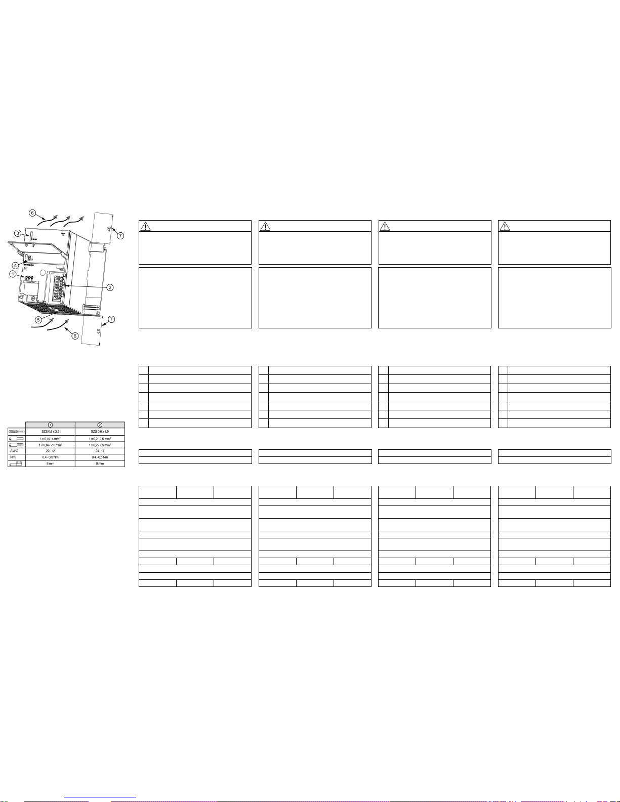
Bild
2: Aufbau
Figure
2: Design
Figura
2: Diseño
图
2: 结构
Figure
2: Structure
Figura
2: Configurazione
Рисунок
2: Конструкция
*1)
Endanschlag nicht höher belasten
*1)
Do not subject the end stop to any higher stress
*1)
Carga máxima del tope de fin de carrera
*1)
末端止挡勿过高负载
*1)
Ne pas appliquer une contrainte plus élevée à la butée de
fin de course
*1)
Non caricare ulteriormente l'arresto di fine corsa
*1)
Не превышать нагрузку на концевой упор
Bild
3: Klemmendaten
Figure
3: Terminal data
Figura
3: Datos de los bornes
图
3: 端子数据
Figure
3: Caractéristiques des bornes
Figura
3: Dati dei morsetti
Рисунок
3: Информация по клеммам
Anschließen
WARNUNG
Vor Beginn der Installations- oder Instandhaltungsarbeiten ist der Hauptschalter der Anlage
auszuschalten und gegen Wiedereins chalten zu
sichern. Bei Nichtbeachtung kann das Berühren
spannungsführender Teile Tod oder schwere
Körperverletzung zur Folge haben.
Für die Installation der Geräte s ind die einschlägigen
länderspezifischen Vorschri ften zu beachten.
Wichtiger Hinweis: Eingangs seitig ist eine Sicherung
oder ein Leitungs- oder Motorsch utzschalter
vorzusehen.
Für 6ES7307-1KA02-0AA0 verwenden sie K upferdraht
zugelassen für 65/75 °C (nur bei UL508) .
Der Anschluss der Versorgungsspannu ng muss gemäß
IEC 60364 und EN 50178 ausgeführt wer den.
Siehe
Bild 3 Klemmendaten (Seite 2)
Siehe
Bild 4 Eingang (Seite 3)
Siehe
Bild 5 Ausgang (Seite 3)
Aufbau
①
AC-Eingang
②
DC-Ausgang
③
Kontrollleuchte
④
ON / OFF Schalter
⑤
Schraube(n) zur Fixierung auf Prof ilschiene
⑥
Konvektion
⑦
Freiraum oberhalb/unterhalb
Siehe
Bild 2 Aufbau (Seite 2)
Betriebsmodus
Signalisierung
LED grün: Ausgangsspannung > 21 V
Siehe
Bild 6 Signalisierung (Seite 3)
Technische Daten
6ES7307-
1BA01-0AA0
6ES7307-
1EA01-0AA0
6ES7307-
1KA02-0AA0
Eingangsgrößen
Eingangsnennspannung U
e nenn
:
1 AC 120/230 V, 50 - 60 Hz
Spannungsbereich: AC 85 - 132/170 - 264 V
automatische Spannungsbereichs umschaltung
Netzfrequenzbereich: 47 - 63 Hz
Netzausfallüberbrückung:
> 20 ms (bei U
e nenn
: 93/187 V)
Eingangsnennstrom I
e nenn
:
0,9/0,5 A
2,3/1,2 A
4,2/1,9 A
Eingangssicherung: intern
Empfohlener Leitungsschutzs chalter Charakteristik C:
3 A
6 A
10 A
Connecting
WARNING
Before starting any installati on or maintenance work,
the main system switch must be opened a nd measures
taken to prevent it from being recl osed. If this
instruction is not observed, touchi ng live parts can
result in death or serious injur y.
For installation of the devices, the relevant countryspecific regulations must be obser ved.
Important note: A fuse, a miniatur e circuit breaker or
circuit breaker must be provi ded at the input.
For 6ES7307-1KA02-0AA0, use copper wir e, approved
for 65/75 °C (only for UL508).
The supply voltage must be connected ac cording to
IEC 60364 and EN 50178.
See
Figure 3 Terminal data (Page 2)
See
Figure 4 Input (Page 3)
See
Figure 5 Output (Page 3)
Structure
①
AC input
②
DC output
③
Indicator light
④
ON / OFF switch
⑤
Screw(s) to fix to the mounting rail
⑥
Convection
⑦
Clearance above/below
See
Figure 2 Design (Page 2)
Operating mode
Signaling
Green LED: Output voltage > 21 V
See
Figure 6 Signaling (Page 3)
Technical data
6ES7307-
1BA01-0AA0
6ES7307-
1EA01-0AA0
6ES7307-
1KA02-0AA0
Input variables
Rated input voltage U
in rated
:
1 AC 120/230 V, 50 - 60 Hz
Rated operating voltage: AC 85 - 132/170 - 264 V
Automatic voltage range switc hover
Line frequency range: 47 - 63 Hz
Power failure buffering:
> 20 ms (at U
in rated
: 93/187 V)
Rated input current I
in rated
:
0.9/0.5 A
2.3/1.2 A
4.2/1.9 A
Input fuse: Internal
Recommended miniat ure circuit breaker charact eristic C:
3 A
6 A
10 A
Conexión
ADVERTENCIA
Antes de comenzar trabajos de inst alación o
mantenimiento, se debe desconect ar el interruptor
principal de la instalación y asegur arlo contra una
posible reconexión. Si no se observ a esta medida, el
contacto con piezas bajo tensión pue de provocar la
muerte o lesiones graves.
A la hora de instalar los aparatos, se tienen que
observar las disposiciones o norm ativas específicas de
cada país.
Nota importante: en el lado de entr ada debe instalarse
un fusible o bien un automático ma gnetotérmico o un
guardamotor.
Para 6ES7307-1KA02-0AA0 utilice hi lo de cobre
homologado para 65/75 °C (solo en UL5 08).
La conexión a la tensión de alimentaci ón debe
realizarse conforme a IEC 60364 y EN 50178.
Ver
Figura 3 Datos de los bornes (Página 2)
Ver
Figura 4 Entrada (Página 3)
Ver
Figura 5 Salida (Página 3)
Diseño
①
Entrada AC
②
Salida DC
③
Lámpara de control
④
Interruptor ON/OFF
⑤
Tornillos para la fijación en el per fil soporte
⑥
Convección
⑦
Espacio libre arriba/abajo
Ver
Figura 2 Diseño (Página 2)
Modo de servicio
Señalización
LED verde: Tensión de salida > 21 V
Ver
Figura 6 Señalización (Página 3)
Datos técnicos
6ES7307-
1BA01-0AA0
6ES7307-
1EA01-0AA0
6ES7307-
1KA02-0AA0
Magnitudes de entrada
Tensión nominal de entrada U
e nom
:
1 AC 120/230 V, 50 - 60 Hz
Rango de tensión: AC 85 - 132/170 - 264 V
Cambio automático de rango de tensi ón
Rango de frecuencia de red: 47 - 63 Hz
Puenteo de fallos de red:
> 20 ms (con U
e nom
: 93/187 V)
Intensidad nominal de entrada I
e nom
0,9/0,5 A
2,3/1,2 A
4,2/1,9 A
Fusible de entrada: interno
Automático magnetotérmico recomen dado curva C:
3 A
6 A
10 A
接线
警告
开始安装或进行维护工作前应该断开装置的总开关,
防止设备重新合闸。违反该规定可能会导致作业人员接
触到带电零部件,从而导致严重的人身伤害甚至死亡。
设备安装同时需遵循本国相关的作业规范。
重要提示:设备输入侧必须配备熔断器、馈线断路器或
者电机断路器。
针对 6ES7307-1KA02-0AA0 使用适用于 65/75 °C 的同
芯线(仅限 UL508)。
必须按照 IEC 60364 和 EN 50178 标准连接供电电压。
参见 图 3 端子数据 (页 2)
参见 图 4 输入 (页 3)
参见 图 5 输出 (页 3)
结构
①
AC 输入
②
DC 输出端
③
LED
④
ON / OFF 开关
⑤
型材导轨固定螺钉
⑥
对流
⑦
上方/下方空间
参见 图 2 结构 (页 2)
运行方式
信号指示
绿色 LED:输出电压 > 21 V
参见 图 6 信号指示 (页 3)
技术数据
6ES7307-
1BA01-0AA0
6ES7307-
1EA01-0AA0
6ES7307-
1KA02-0AA0
输入变量
额定输入电压 U
额定输入
:
单相 120/230 V AC,50 - 60 Hz
电压范围:85 - 132/170 - 264 V AC
电压范围自动转换
电网频率范围:47 - 63 Hz
断电缓冲:
> 20 ms(在 U
额定输入
时:93/187 V)
额定输入电流 I
额定输入
:
0.9/0.5 A
2.3/1.2 A
4.2/1.9 A
输入点熔断器:内置
推荐的小型断路器(C 特性):
3 A
6 A
10 A
 Loading...