

Siemens SIMATIC PP7, SIMATIC PP17-I, SIMATIC PP17-II Equipment Manual
Preface, Contents
该文档是极速PDF编辑器生成,
如果想去掉该提示,请访问并下载:
http://www.jisupdfeditor.com/
长沙工控帮教育科技有限公司
www.gkbpx.com
SIMATIC HMI
PP7, PP17-I, PP17-II
Push Button Panels
Equipment Manual
Product Description
Starting Up the Push Button
Panel
Control Bit Assignment
Installation
Unit Description PP7
Unit Description PP17-I
Unit Description PP17-II
Attach Labeling Strips
Spare Parts
1
2
3
4
5
6
7
8
9
6AV3991–1CA00–0AB0
Technical Data
System Messages
Hardware Test
Siemens Worldwide
Index
A
B
C
D
Release 06/98
Safety
该文档是极速PDF编辑器生成,
如果想去掉该提示,请访问并下载:
http://www.jisupdfeditor.com/
长沙工控帮教育科技有限公司
www.gkbpx.com
Guidelines
!
!
This manual contains notices which you should observe to ensure your own personal safety, as
well as to protect the product and connected equipment. These notices are highlighted in the
manual by a warning triangle and are marked as follows according to the level of danger:
Warning
indicates that death, severe personal injury or substantial property damage can result if proper
precautions are not taken.
Caution
indicates that minor personal injury or property damage can result if proper precautions are not
taken.
Note
draws your attention to particularly important information on the product, handling the product,
or to a particular part of the documentation.
Qualified Personnel
Correct Usage
!
Trademarks
Equipment may be commissioned and operated only by qualified personnel. Qualified personnel within the meaning of the safety notices in this manual are persons who are authorized to
commission, ground and identify equipment, systems and circuits in accordance with safety
engineering standards.
Note the following:
Warning
The equipment may be used only for the applications stipulated in the catalog and in the technical description and only in conjunction with other equipment and components recommended
or approved by Siemens.
Startup must not take place until it is established that the machine, which is to accommodate
this component, is in conformity with the guideline 89/392/EEC.
Faultless and safe operation of the product presupposes proper transportation, proper storage,
erection and installation as well as careful operation and maintenance.
SIMATIC is a registered trademark of Siemens AG.
Some of the other designations used in these documents are also registered trademarks; the
owner’s rights may be violated if they are used be third parties for their own purposes.
Impressum
Copyright
The reproduction, transmission or use of this document or its
contents is not permitted without express written authority.
Offenders will be liable for damages. All rights, including rights
created
are reserved.
Siemens AG,
Bereich Automatisierungstechnik,
Bedienen und Beobachten
Postfach 4848,
Siemens Aktiengesellschaft
Editor and Publisher: A&D PT1
Siemens
by patent grant or registration of
AG 1996 All rights reserved
D-90327 Nuernberg
a utility model or design,
Disclaimer of Liability
W
e have checked the contents of this manual for agreement with
the
hardware and software described. Since deviations cannot be
precluded
the
corrections included in subsequent editions. Suggestions for improvement
T
echnical data subject to change.
Order No. 6A
entirely
data in this manual are reviewed regularly and any necessary
Siemens
Equipment
, we cannot guarantee full agreement. However
are welcomed.
AG 1997
V3991–1CA00–0AB0
Manual TP37
,
Preface
该文档是极速PDF编辑器生成,
如果想去掉该提示,请访问并下载:
http://www.jisupdfeditor.com/
长沙工控帮教育科技有限公司
www.gkbpx.com
Purpose
This
equipment manual is designed to provide operators, installation personnel,
planners and system maintenance technicians with information concerning the
functionality
, operation and technical configuration of Push Button Panels.
Organization of the
manual
Further support
The
equipment manual for the Push Button Panels PP7, PP17-I and PP17-II
divided into the following sections:
Chapters Content
1
2
3
4
5 - 7
8
9
Appendices T
Please address technical questions to your local Siemens partners in the subsid
iaries and branch of
equipment manual for a list of addresses.
General description of the Push Button Panels
Step-by-step instructions on how to configure a Push
Button Panel
Detailed information on the interrelationship between the
Push Button Panel and PLC
Mechanical and electrical installation of the Push Button
Panels
Unit description of the various Push Button Panel
versions
Information on labelling
Information on spare parts
echnical data, system messages, hardware test
fices responsible for your area. Refer to Appendix D of this
is
-
PP7,
Release 06/98
PP17-I, PP17-II Equipment Manual
i
SIMATIC Customer Support Hotline
该文档是极速PDF编辑器生成,
如果想去掉该提示,请访问并下载:
http://www.jisupdfeditor.com/
长沙工控帮教育科技有限公司
www.gkbpx.com
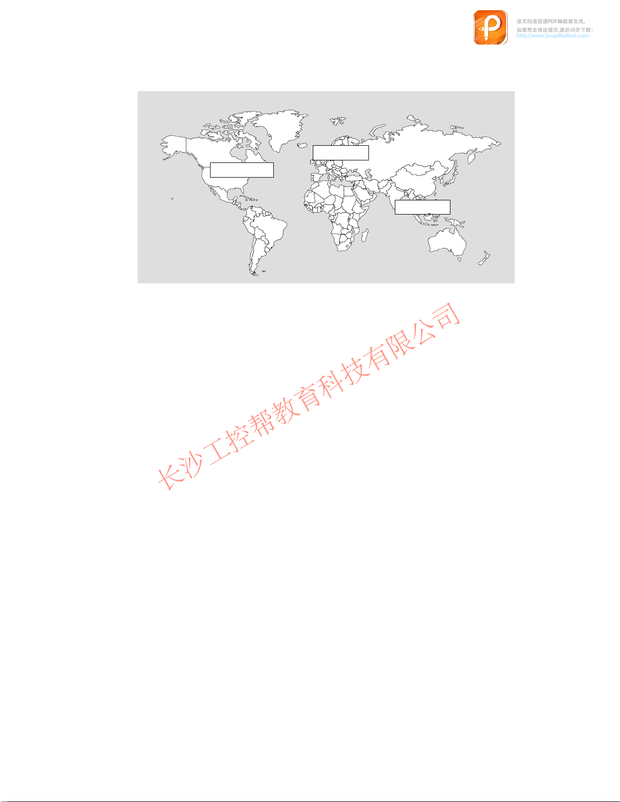
Available worldwide around the clock:
Johnson City
Nuremberg
Singapore
Nuremberg
SIMATIC BASIC Hotline
Local
time:
Mon-Fri 8:00 to
18:00
Tel.:
Fax:
E-mail: simatic.support@
SIMATIC
(chargeable,
SIMA
Times:
Tel.:
Fax:
+49 (911) 895-7000
+49 (911) 895-7002
nbgm.siemens.de
Premium Hotline
TIC Card required)
Mon-Fri 0:00 to
24:00
+49 (911) 895-7777
+49 (911) 895-7001
Simatic
Basic Hotline
Johnson City
SIMATIC BASIC Hotline
Local time:
Tel.:
Fax:
E-mail: simatic.hotline@
Mon-Fri 8:00 to
17:00
+1 423 461-2522
+1 423 461-2231
sea.siemens.com
Singapore
SIMATIC BASIC Hotline
Local time:
Tel.:
Fax:
E-mail: simatic@
Mon-Fri 8:30 to
17:30
+65 740-7000
+65 740-7001
singnet.com.sg
ii
PP7,
PP17-I, PP17-II Equipment Manual
Release 06/98

SIMATIC Customer Support Online Services
该文档是极速PDF编辑器生成,
如果想去掉该提示,请访问并下载:
http://www.jisupdfeditor.com/
长沙工控帮教育科技有限公司
www.gkbpx.com
SIMATIC
MA
Customer Support offers you comprehensive additional information about SI
TIC products through its Online Services as follows:
Up-to-date general information is provided
–
on the
internet
–
from the
Up-to-date product information and downloads for practical use can be found
–
on the
internet
html–00/
–
from the
tomer Support Mailbox)
For calling up the mailbox, you should use a modem with up to
V
.34 (28.8 kBaud) capability and set the parameters as follows: 8, N, 1,
ANSI, or connect via ISDN (x.75, 64 kBit).
at
http://www.ad.siemens.de/simatic
fax polling service on
at
http://www.ad.siemens.de/support/
Bulletin Board System
on +49 (91
08765-93 02 77 95 00
(BBS) in Nurember
1) 895-7100.
g (
SIMA
-
TIC Cus
-
PP7, PP17-I, PP17-II Equipment Manual
Release 06/98
iii

iv
该文档是极速PDF编辑器生成,
如果想去掉该提示,请访问并下载:
http://www.jisupdfeditor.com/
长沙工控帮教育科技有限公司
www.gkbpx.com
PP7,
PP17-I, PP17-II Equipment Manual
Release 06/98

Contents
该文档是极速PDF编辑器生成,
如果想去掉该提示,请访问并下载:
http://www.jisupdfeditor.com/
长沙工控帮教育科技有限公司
www.gkbpx.com
1 Product
1.1 Push
1.2 Operating
2 Starting Up the Push Button Panel 2-1.
2.1 Configure
2.2 Define
2.2.1 MPI
2.2.2 PROFIBUS-DP
2.3 Configuring
2.3.1 Configuring
2.3.2 Configuring
2.4 Coordinating
3 Control
4 Installation 4-1
5 Unit
6 Unit
7 Unit
8 Attach
Description
Button Panel Overview
Configuration in PLC
connection
Bit Assignment
. . . . . . . . . . . . . . . . . . . . . . . . . . . . . . . . . . . . . . . . . . . . . . . . . . . . . . . . . . . . . .
Description PP7
Description PP17-I
Description PP17-II
Labeling Strips
. . . . . . . . . . . . . . . . . . . . . . . . . . . . . . . . . . . . . . . . . . . . . . . . . . . .
and Display Elements
Interface to PLC on the Push Button Panel
Keys/LEDs
Keys/LEDs When Using MPI Connection
Keys/LEDs When Using PROFIBUS-DP Connection
the Push Button Panel and PLC
. . . . . . . . . . . . . . . . . . . . . . . . . . . . . . . . . . . . . . . . . . . . . . . . . . . .
. . . . . . . . . . . . . . . . . . . . . . . . . . . . . . . . . . . . .
. . . . . . . . . . . . . . . . . . . . . . . . . . . . . . . . . .
. . . . . . . . . . . . . . . . . . . . . . . . . . . . . . . . . . . . . . .
. . . . . . . . . . . . . . . .
. . . . . . . . . . . . . . . . . . . . . . . . . . . . . . . . . . . . . .
. . . . . . . . . . . . . . . . . . . . . . . . . . . . . . . . . . . . . . . . . . . . . . . . .
connection
. . . . . . . . . . . . . . . . . . . . . . . . . . . . . . . . . . . . . . . . . . . . . . . . .
. . . . . . . . . . . . . . . . . . . . . . . . . . . . . . . . . . . . . . . . . . . . . . . . .
. . . . . . . . . . . . . . . . . . . . . . . . . . . . . . . . . . . . . . . . . . . . . . . . .
. . . . . . . . . . . . . . . . . . . . . . . . . . . . . . . . . . . . . . . . . . . . . . . . . .
. . . . . . . . . . . . . . . . . . . . . . . . . . . . . . . . . . . . . . .
. . . . . . . . . . . . . . . . . . . . . . . . . . . . . . . . . . . . . . . . . .
. . . . . . . . . . . . . . . .
. . . . . .
. . . . . . . . . . . . . . . . . . . . . . .
2-11.
2-12.
2-13.
1-1.
1-3.
1-4.
2-3.
2-6.
2-6.
2-6.
2-9.
3-1.
5-1.
6-1.
7-1.
8-1.
9 Spare
A Technical
B System
C Hardware Test C-1.
D Siemens Worldwide D-1.
PP7, PP17-I, PP17-II Equipment Manual
Release 06/98
Parts
A.1 General
A.2 Digital
A.3 Interface
. . . . . . . . . . . . . . . . . . . . . . . . . . . . . . . . . . . . . . . . . . . . . . . . . . . . . . . . . . . .
Data
inputs and outputs
Messages
. . . . . . . . . . . . . . . . . . . . . . . . . . . . . . . . . . . . . . . . . . . . . . . . . . . . . . . . .
technical data
assignment
. . . . . . . . . . . . . . . . . . . . . . . . . . . . . . . . . . . . . . . . . . . . . . . . . . . . . .
. . . . . . . . . . . . . . . . . . . . . . . . . . . . . . . . . . . . . . . . . . . . . . . . . . . . . . . . . .
. . . . . . . . . . . . . . . . . . . . . . . . . . . . . . . . . . . . . . . . . . . . . . . . . . . .
9-1.
A-1.
. . . . . . . . . . . . . . . . . . . . . . . . . . . . . . . . . . . . . . . . . . .
. . . . . . . . . . . . . . . . . . . . . . . . . . . . . . . . . . . . . . . .
. . . . . . . . . . . . . . . . . . . . . . . . . . . . . . . . . . . . . . . . . . . .
A-1.
A-2.
A-4.
B-1.
v

vi
该文档是极速PDF编辑器生成,
如果想去掉该提示,请访问并下载:
http://www.jisupdfeditor.com/
长沙工控帮教育科技有限公司
www.gkbpx.com
PP7, PP17-I, PP17-II Equipment Manual
Release 06/98

Product Description
该文档是极速PDF编辑器生成,
如果想去掉该提示,请访问并下载:
http://www.jisupdfeditor.com/
长沙工控帮教育科技有限公司
www.gkbpx.com
The
Use of Push
Button Panels
Push Button Panels can be used to display the operating statuses of a
machine or system and to control processes.
1
Until now
for this purpose. This was also a time-consuming process. In contrast to this,
installation of Push Button Panels requires only a rectangular cut-out and a bus
connection (DP or MPI). The standard configuration ensures that the panel is
ready to operate immediately after all the connections have been made. This
results in considerable advantages in respect of time compared to conventional
connections.
The Push Button Panels provide a lar
without the necessity of PLC programs:
Color
, keys and lamps had to be individually mounted, wired and tested
ge variety of features which can be used
Short-stroke keys with surface illumination according to the LED colors
Additional 24 V digital inputs and outputs
All short-stroke keys and digital 24 V inputs can also be individually
configured as switches
Integrated lamp and key test
Central release input to lock all operating actions
Integrated flash timing
-coding for LEDs, such as red, green, orange
Pulse extension for short-stroke keys and digital 24 V inputs can be
specified via parameters
Perforated cut-outs for 22.5 mm standard optional elements, such as
key-operated switch and emer
gency shutdown switch
Installation
possibilities
PP7, PP17-I, PP17-II Equipment Manual
Release 06/98
OP design, can be set in rows, without gaps
The Push Button Panels have been conceived for installation in cabinets and
can be implemented in all situations where keys, switches and lamps are re
quired.
The high degree of protection (IP65 on the front side) and the fact they are
maintenance-free make the Push Button Panels suitable for use even in rough
industrial environments.
-
1-1

Connection types
该文档是极速PDF编辑器生成,
如果想去掉该提示,请访问并下载:
http://www.jisupdfeditor.com/
长沙工控帮教育科技有限公司
www.gkbpx.com
The
Push Button Panels can be operated using the following connections:
via MPI to a SIMA
via MPI to a SIMA
via MPI to a SIMA
via PROFIBUS-DP to a SIMA
via PROFIBUS-DP to a SIMA
via PROFIBUS-DP as standard slave to a DP master from a dif
manufacturer; possible restrictions regarding configuration of the Push
Button Panel.
TIC S7-200
TIC S7-300
TIC S7-400
TIC S5
TIC S7
ferent
Unit configuration
Parameters in the Push Button Panels are predefined and the unit is thus imme
diately ready to operate. V
certain parameters. Each key
adapted according to specific requirements.
No special configuration software is necessary for the Push Button Panel. All
adjustment of the settings is carried out either directly on the Push Button
Panel or by means of the PLC configuration software.
All adjustments to settings carried out on the Push Button Panel are stored in
its memory module. In cases where the unit electronics or the entire unit are
replaced, the interface need not be reconfigured. Only the old memory module
needs to be transferred to the new unit.
arious options can also be activated by adjusting
, LED, digital input and output can be individually
-
1-2
PP7,
PP17-I, PP17-II Equipment Manual
Release 06/98
1.1 Push
该文档是极速PDF编辑器生成,
如果想去掉该提示,请访问并下载:
http://www.jisupdfeditor.com/
长沙工控帮教育科技有限公司
www.gkbpx.com
Short-stroke
keys, surface illumination
Inputs/Outputs
p p
Installable operating elements
Release input Lock operation of the
Interfaces PLC connection MPI or Profibus DP
Communication SIMATIC S5
Data transmission
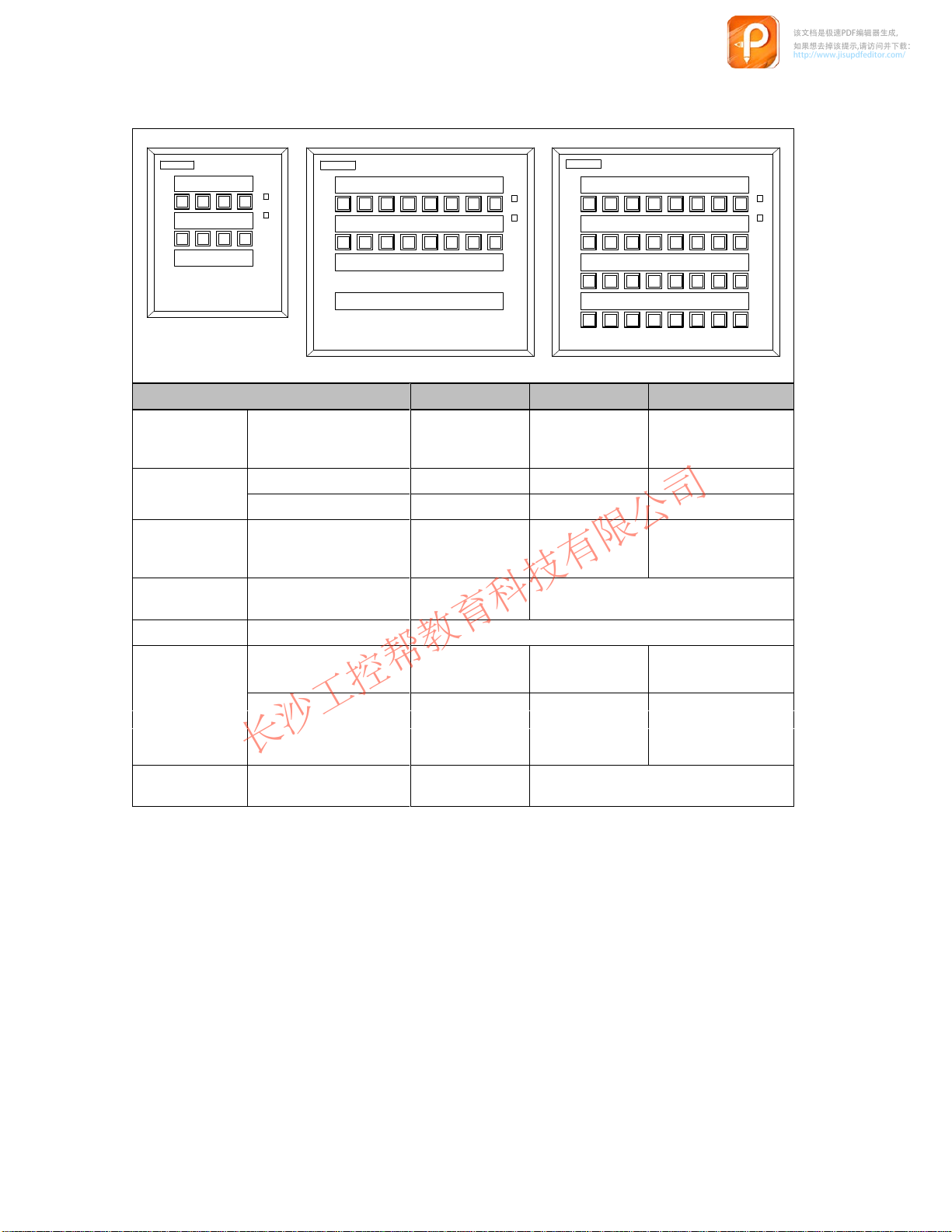
Button Panel Overview
PP7 PP17-I PP17-II
Hardware PP7 PP17-I PP17-II
Number of short-stroke
-
keys
Number of digital inputs 4 16 16
Number of digital outputs - 16 16
Number of 22.5 mm ele-
ments which can be integrated
Push Button Panel
–
– PROFIBUS-DP
SIMATIC S7/M7
SIMATICS7/M7
–
– MPI
– PROFIBUS-DP
PROFIBUS DP
Baud rate Max. 1.5 MBaud Max. 12 MBaud
-
8 16 32
3 12 –
-
PP7,
Release 06/98
PP17-I, PP17-II Equipment Manual
1-3

1.2 Operating and Display Elements
该文档是极速PDF编辑器生成,
如果想去掉该提示,请访问并下载:
http://www.jisupdfeditor.com/
长沙工控帮教育科技有限公司
www.gkbpx.com
The
Standard operating
and display elements
Push Button Panels are all equipped with a keyboard containing shortstroke keys. The individual keys can be configured in respect of their function
as either switches or keys.
Function momentary–contact switch:
The corresponding bit in the PLC is set as long as the
key is pressed.
Operating concept
Digital inputs and
outputs
Release input
Function switches:
T
wo LEDs are integrated in the keys and are used to display the bit status of
the connected PLC. The LEDs can indicate four dif
which can be defined via parameters.
All the operating elements of the Push Button Panels are linked to bits in the
PLC. The keys on the Push Button Panel can be used to influence the bits in
the PLC and thus control the af
indicate the bit status of the PLC and, thus, the operating status of the process
being monitored.
When several keys are pressed simultaneously
ton Panel and the bits are set in the PLC. After restarting the system following
a power failure, all the bits are set to 0.
Additional 22.5 mm elements can be connected using the digital inputs and
outputs. Non-connected digital inputs are automatically set to 0.
The release input serves to lock the Push Button Panel. A key-operated switch
can be connected here, for example. The release input permits switching be
tween normal operation (open contact) and monitoring mode (closed contact).
In normal operation, all the functions on the Push Button Panel are available
for use, whereas in monitoring mode, the following restrictions are valid
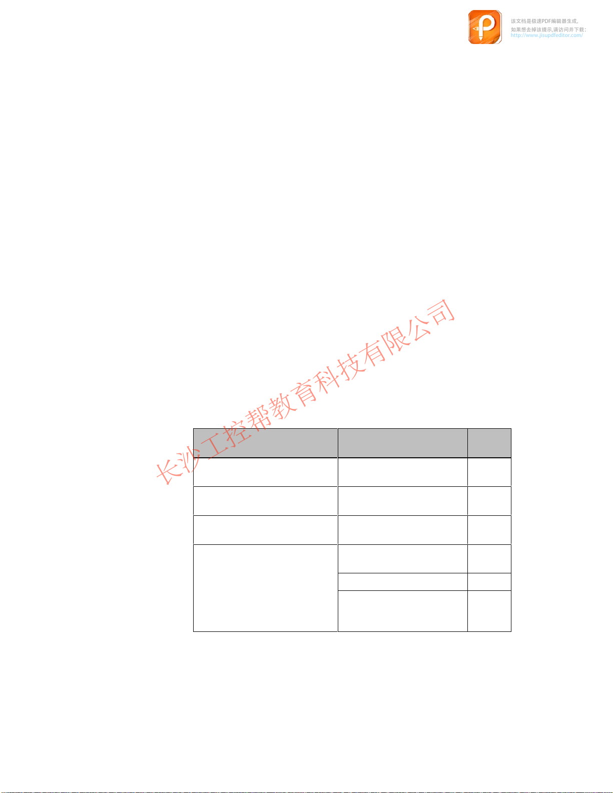
Pressing the key sets the corresponding bit, pressing
again resets it.
ferent statuses, one of
fect of processes. At the same time, the LEDs
, it is detected by the Push But
-
-
1-4
the inputs are locked, no signal exchanges are reported to the PLC,
the last status of all the keys is maintained by the PLC until normal
operation returns.
PP7,
PP17-I, PP17-II Equipment Manual
Release 06/98
Pulse
该文档是极速PDF编辑器生成,
如果想去掉该提示,请访问并下载:
http://www.jisupdfeditor.com/
长沙工控帮教育科技有限公司
www.gkbpx.com
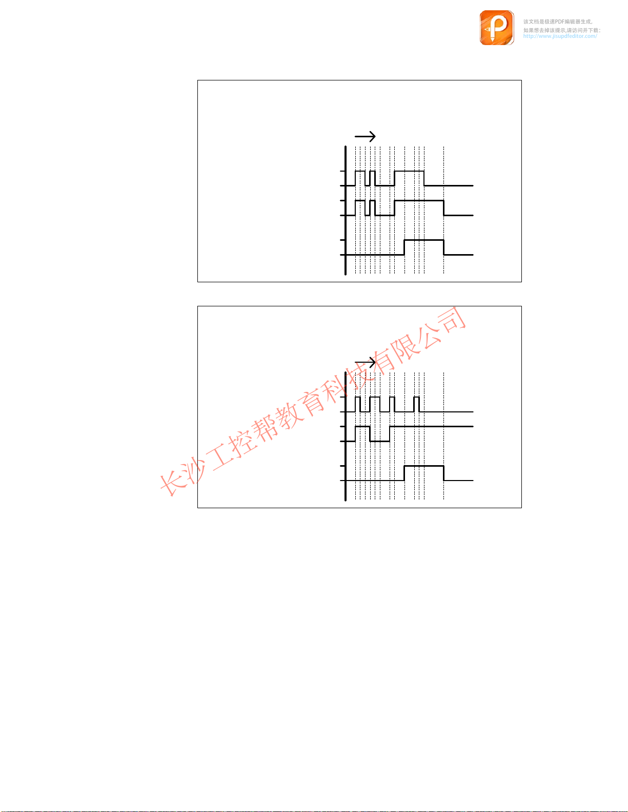
diagrams
The
following pulse diagrams elucidate the relationship between the actions
initiated on the Push Button Panel and changing bit status in the PLC:
Function
Key
Bit
in
PLC
Contact
Release
input
Key
Bit
in
PLC
as momentary–contact switch
Time
pressed
not pressed
1
0
closed
open
Function as switch
Time
pressed
not pressed
1
0
Lamp/Key test
PP7,
PP17-I, PP17-II Equipment Manual
Release 06/98
Contact
Release
input
The
Lamp/Key test serves to test the functional capabilitity of all the keys and
closed
open
lamps on the Push Button Panel. The Lamp/Key test can be activated by the
following measures in normal operation:
By pressing the key assigned to the Lamp/Key test function by the
corresponding parameter
By setting the two LED bits of the key assigned to the Lamp/Key test
.
function according to the configuration. The bits must be set in the PLC
using a relevant program.
The Lamp/Key test function is assigned to Key 1 (top right) in the pre-adjusted
system settings.
1-5

On
该文档是极速PDF编辑器生成,
如果想去掉该提示,请访问并下载:
http://www.jisupdfeditor.com/
长沙工控帮教育科技有限公司
www.gkbpx.com
activating the Lamp/Key test, the unit switches to the corresponding oper
ating mode. In this case
the ERROR LED blinks,
the LEDs integrated in the Push Button Panel keyboard are activated,
all the Push Button Panel digital outputs are set to 1.
After pressing any key when in operating mode Lamp/Key test,
the LED/lamps go out for the period in which the key is pressed,
all the Push Button Panel digital outputs are set to 1.
This is valid for the period in which the key is pressed. All the keys and digital
inputs can be tested in this way
In order that no unwanted signals are transmitted to the PLC during the Lamp/
Key test, the following restrictions are valid in respect of Push Button Panel
operation:
the inputs are locked and no signal exchanges are reported to the PLC,
the last status of all the keys is maintained by the PLC until normal
operation returns.
The last key operation reported to the PLC is the pressing of the Lamp/Key test
button.
T
o terminate the Lamp/Key test,
.
-
release the corresponding key
reset the corresponding bits in the PLC
The unit returns to normal operation and the restrictions regarding the Push
Button Panel operation are released.
, or
1-6
PP7,
PP17-I, PP17-II Equipment Manual
Release 06/98
Starting Up the Push Button Panel
该文档是极速PDF编辑器生成,
如果想去掉该提示,请访问并下载:
http://www.jisupdfeditor.com/
长沙工控帮教育科技有限公司
www.gkbpx.com
The
following section provides help regarding the configuration possibilities of
the Push Button Panel. Connection type MPI is pre-selected in the system set
tings.
2
-
MPI connection
The system settings for the MPI connection are:
MPI address:
Baud rate:
Data area type:
Memory word:
Configuring data block:
PLC address:
PLC type:
Highest station address:
Number of MPI masters:
The following table provides an overview of the possibilities for modifying the
defined system settings:
Intention Procedure Chap-
Modify MPI address
Change baud rate Change baud rate on Push
Change data area type
Configure Push Button Panel
properties which deviate from
p p
dj d i
pre-adjusted system settings
3
187.5 KBaud
Marker byte
100
0
2
300 (S7-300)
126
1
Set MPI address on Push
Button Panel
Button Panel
Change data area type on
Push Button Panel
Set up configuring data block
in the PLC
Set parameter
ters
2.1
2.1
2.1
2.3.1
2.3
PP7,
Release 06/98
PP17-I, PP17-II Equipment Manual
Set the number of the config
uring data block on the Push
Button Panel
-
2.1
2-1
h devi
DP connection
该文档是极速PDF编辑器生成,
如果想去掉该提示,请访问并下载:
http://www.jisupdfeditor.com/
长沙工控帮教育科技有限公司
www.gkbpx.com
The
system settings for the DP connection are:
DP slave address:
Baud rate:
The following table provides an overview of the possibilities for modifying the
defined system settings:
Intention Procedure Chap-
Set connection type DP Set connection type DP on the
Change DP slave address
Change baud rate Change baud rate on Push
Configure Push Button Panel
properties whic
pre-adjusted system settings
ate from
3
1500 KBaud
Push Button Panel
Change the DP slave address
on the Push Button Panel
Button Panel
Set parameter in the configu-2.3
ration software
ters
2.1
2.1
2.1
2-2
PP7,
PP17-I, PP17-II Equipment Manual
Release 06/98
2.1 Configure Interface to PLC on the Push Button Panel
该文档是极速PDF编辑器生成,
如果想去掉该提示,请访问并下载:
http://www.jisupdfeditor.com/
长沙工控帮教育科技有限公司
www.gkbpx.com
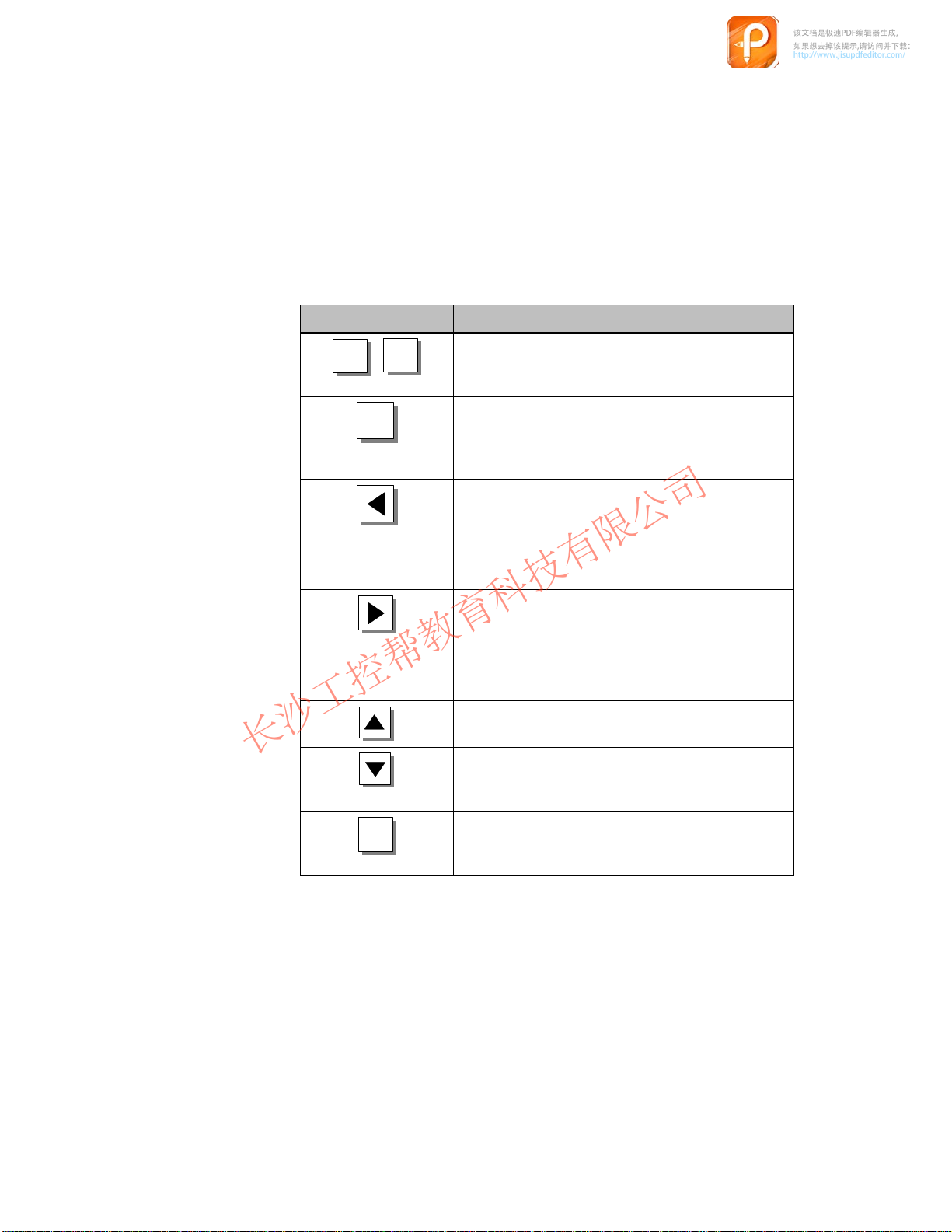
The
Calling in and
operating
configuration
mode
settings of the interface to the PLC are menu-controlled and can be de
fined via the rear side display of the Push Button Panel. The so-called configu
ration mode is provided for this.
All the parameters concerning the interface to the PLC are stored in the Push
Button Panel memory module. In cases where the unit electronics or the entire
unit are replaced, the interface need not be reconfigured. Only the old memory
module needs to be transferred to the new unit.
Key Description
-
-
ESC
OK
+
If this key combination is pressed while the unit is
starting up (directly after switching on), the unit
enters configuration mode.
OK
In configuration mode, this key serves to store a
modification in the current menu level and skip for
ward to the next menu level. The key has no func
-
-
tion in the bottom menu level.
In configuration mode, this key serves to skip back
to the superordinated menu level. The key has no
function in the top menu level.
Caution: Any modifications carried out to the set
-
tings in the current menu level are not stored.
In configuration mode, this key serves to skip for
ward to the next menu level. The key has no func
-
-
tion in the bottom menu level.
Caution: Any modifications carried out to the set
-
tings in the current menu level are not stored.
In configuration mode, this key serves to scroll up
-
wards through the alternatives within a menu level.
In configuration mode, this key serves to scroll
downwards through the alternatives within a menu
level.
PP7,
Release 06/98
PP17-I, PP17-II Equipment Manual
ESC
This key serves to exit from configuration mode.
The current settings are stored. The key can be
operated in any menu level.
2-3
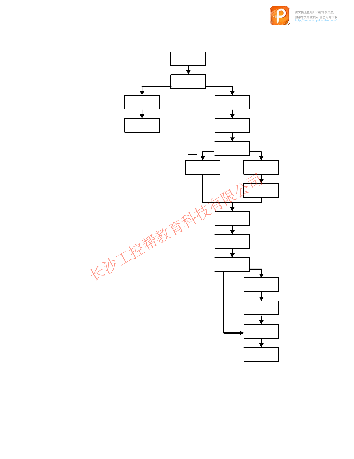
The
该文档是极速PDF编辑器生成,
如果想去掉该提示,请访问并下载:
http://www.jisupdfeditor.com/
长沙工控帮教育科技有限公司
www.gkbpx.com
following menu structure is displayed in configuration mode (the numeric
values and underlined alternatives indicate the predefined system settings):
DEFAULT
YES / NO
CONNECTION
DP
DP MPI
/ MPI
SLAVE-ADR
BAUDRATE
3
1500 KBaud
100
MB
MW
PP-MPI-ADR
BAUDRATE
MB / DB
PARAM.-DB
PLC-ADR
PLC-TYPE
2 / 3 / 400
200
DATA
300
3
187,5 KBaud
DB
DB
DW
0
2
400
RACK-NO
100
0
0
2-4
SLOT-NO
HSA
NUMBER OF
MPI-MASTER
PP7,
PP17-I, PP17-II Equipment Manual
3
126
1
Release 06/98
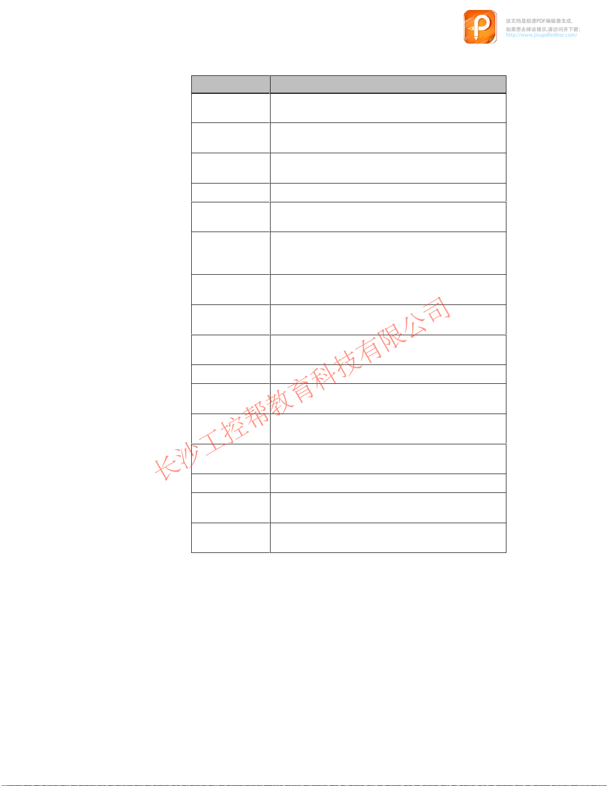
Refer
该文档是极速PDF编辑器生成,
如果想去掉该提示,请访问并下载:
http://www.jisupdfeditor.com/
长沙工控帮教育科技有限公司
www.gkbpx.com
to the following table for the significance of the various menu items:
Name Explanation
DEFAULT
CONNECTION
DP/MPI
SLAVE-ADR
PP-MPI-ADR
BAUDRATE
DAT
A MB/DB
MW
DB
DW
PARAM.-DB
Used to select whether all the parameters should be reset
to the predefined system settings values.
Used to select the system connection type. Either MPI or
PROFIBUS-DP.
Defines the slave address of the Push Button Panel in
the PROFIBUS-DP system.
Defines the MPI address of the Push Button Panel.
Defines the baud rate for data transmission using con
nection type MPI or PROFIBUS-DP in KBaud.
Used to select whether the data area for the Push Button
Panel is created as a Memory Byte (MB) or Data Block
(DB).
Defines the number of the first, reserved memory word
for the Push Button Panel.
Defines the number of the data block in which the data
area for the Push Button Panel is reserved.
Defines the number of the first, reserved data word for
the Push Button Panel in the data block.
Defines the number of the configuring data block.
-
PLC-ADR
PLC-TYPE
2/3/400
RACK-NO
SLOT-NO
HSA
NUMBER OF
MPI-MASTER
Defines the address of the PLC to which the Push But
ton Panel is connected.
Used to select the type of PLC to which the Push Button
Panel is connected.
Defines the number of the rack in which the PLC is
installed.
Defines the number of the slot within the rack.
Defines the highest station address within the MPI sys
tem.
Defines the number of the MPI master in the system.
-
-
PP7,
Release 06/98
PP17-I, PP17-II Equipment Manual
2-5
2.2 Define Configuration in PLC
该文档是极速PDF编辑器生成,
如果想去掉该提示,请访问并下载:
http://www.jisupdfeditor.com/
长沙工控帮教育科技有限公司
www.gkbpx.com
2.2.1 MPI connection
If
connection type MPI is used for the Push Button Panel, no hardware config
uration is necessary
Panel.
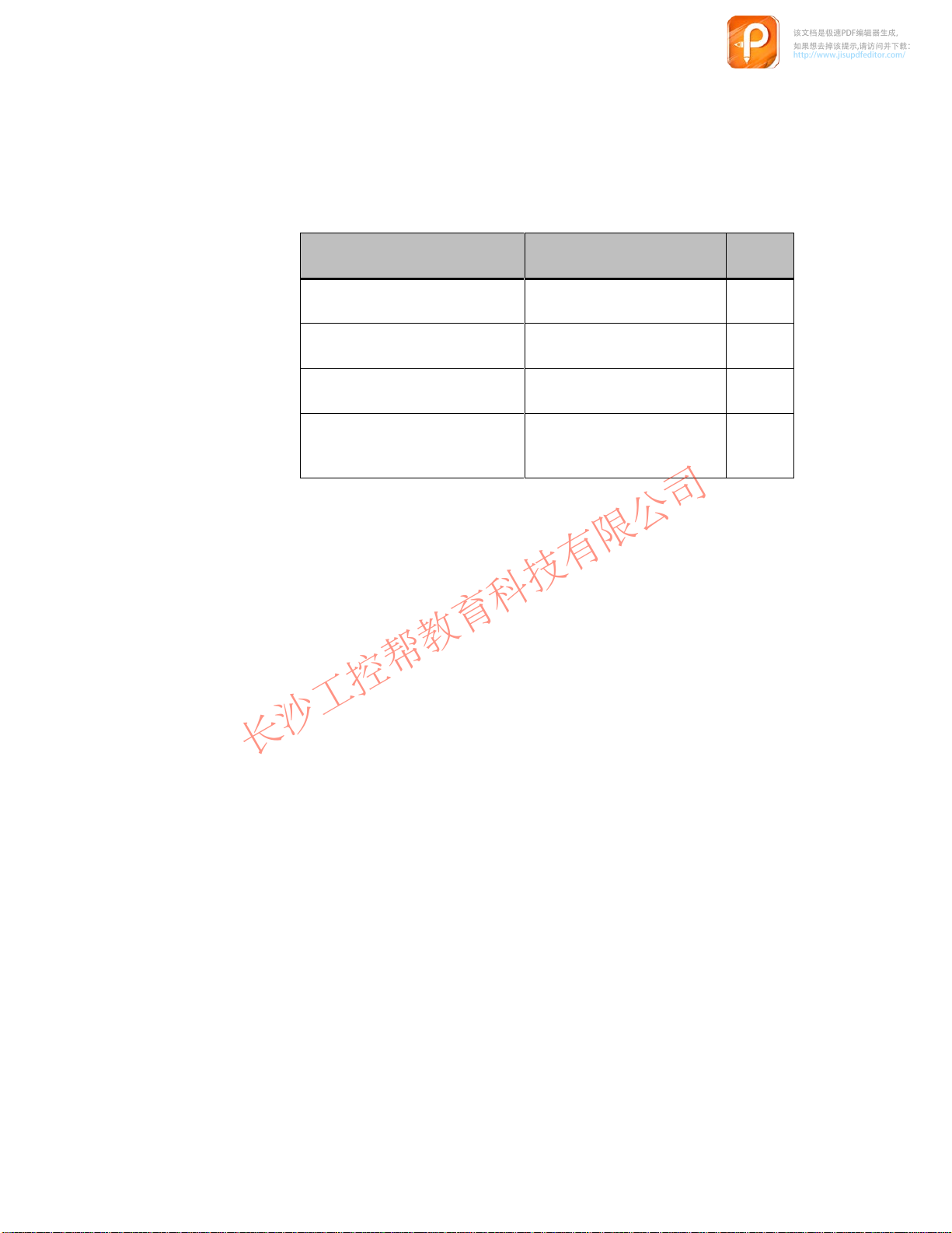
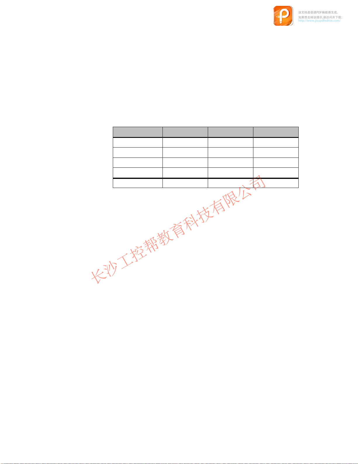
Interrelated memory areas must be set up in the PLC for the keys, LEDs and
digital inputs and outputs. The following table indicates the length of the
memory areas to be set up for the various unit versions.
. Only the MPI address needs to be set on the Push Button
-
Memory ar
Keys
Digital inputs
LEDs
Digital outputs
Total
In order to modify system settings, a data block must be created in the PLC
which contains the configuration data for the Push Button Panel. The structure
of this configuring data block is depicted in Chapter 2.4. The number of the
configuring data block must be specified when configuring the Push Button
Panel.
ea PP7 PP17-I PP17-II
2.2.2 PROFIBUS-DP connection
When
connection type PROFIBUS-DP is used, the Push Button Panel must be
installed in the PROFIBUS configuration software as a slave in the network. In
the case of SIMA
and for SIMA
CONFIG. The configuration software defines the following:
TIC S5, the configuration software used is COM-PROFIBUS,
TIC S7 connection to the network is performed via HW
1 Byte
1 Byte
2 Bytes 4 Bytes 8 Bytes
–
4 Bytes
2 Bytes 4 Bytes
2 Bytes 2 Bytes
4 Bytes 4 Bytes
12 Bytes 18 Bytes
-
2-6
station address,
the I/O area used
and the configuration of the buttons and LEDs.
Ensure that the same station address is specified that is set on the Push Button
Panel.
PP7,
PP17-I, PP17-II Equipment Manual
Release 06/98
 Loading...