

Siemens SIMATIC PN/M-Bus LINK Operating Instructions Manual
Operating Instructions
SIMATIC
Network transitions
PN/M-Bus LINK
03/2018Edition
siemens.com


___________________
___________________
___________________
___________________
___________________
___________________
___________________
___________________
___________________
___________________
___________________
___________________
___________________
SIMATIC
03/2018
A5E44260928
Introduction
1
Safety information
2
System overview
3
Functions
4
Application planning
5
Mounting/Extending
6
Connecting
7
Commissioning
8
Configuring / Programming
9
Diagnostics
10
Maintenance and service
11
Technical specifications
12
Appendix
A
Network transitions
P
N/M-Bus LINK
Operating Instructions
-AA

Siemens AG
Division Digital Factory
Postfach 48 48
90026 NÜRNBERG
GERMANY
A5E44260928-AA
Ⓟ
Copyright © Siemens AG 2018.
All rights reserved
Legal information
Warning notice system
DANGER
indicates that death or severe personal injury will result if proper precautions are not taken.
WARNING
indicates that death or severe personal injury may result if proper precautions are not taken.
CAUTION
indicates that minor personal injury can result if proper precautions are not taken.
NOTICE
indicates that property damage can result if proper precautions are not taken.
Qualified Personnel
personnel qualified
Proper use of Siemens products
WARNING
Siemens products may only be used for the applications described in the catalog and in the relevant technical
ambient conditions must be complied with. The information in the relevant documentation must be observed.
Trademarks
Disclaimer of Liability
This manual contains notices you have to observe in order to ensure your personal safety, as well as to prevent
damage to property. The notices referring to your personal safety are highlighted in the manual by a safety alert
symbol, notices referring only to property damage have no safety alert symbol. These notices shown below are
graded according to the degree of danger.
If more than one degree of danger is present, the warning notice representing the highest degree of danger will
be used. A notice warning of injury to persons with a safety alert symbol may also include a warning relating to
property damage.
The product/system described in this documentation may be operated only by
task in accordance with the relevant documentation, in particular its warning notices and safety instructions.
Qualified personnel are those who, based on their training and experience, are capable of identifying risks and
avoiding potential hazards when working with these products/systems.
Note the following:
documentation. If products and components from other manufacturers are used, these must be recommended
or approved by Siemens. Proper transport, storage, installation, assembly, commissioning, operation and
maintenance are required to ensure that the products operate safely and without any problems. The permissible
All names identified by ® are registered trademarks of Siemens AG. The remaining trademarks in this publication
may be trademarks whose use by third parties for their own purposes could violate the rights of the owner.
We have reviewed the contents of this publication to ensure consistency with the hardware and software
described. Since variance cannot be precluded entirely, we cannot guarantee full consistency. However, the
information in this publication is reviewed regularly and any necessary corrections are included in subsequent
editions.
for the specific
04/2018 Subject to change

Table of contents
1 Introduction ............................................................................................................................................. 5
2 Safety information ................................................................................................................................... 7
3 System overview ................................................................................................................................... 10
4 Functions .............................................................................................................................................. 15
5 Application planning .............................................................................................................................. 19
6 Mounting/Extending .............................................................................................................................. 24
7 Connecting ........................................................................................................................................... 26
1.1 Preface ...................................................................................................................................... 5
1.2 Documentation guide ................................................................................................................ 6
2.1 Safety information ..................................................................................................................... 7
2.2 Security information .................................................................................................................. 9
2.3 IT security ................................................................................................................................. 9
3.1 Field of application .................................................................................................................. 10
3.2 Features .................................................................................................................................. 11
3.3 System configuration .............................................................................................................. 12
3.4 System requirements .............................................................................................................. 13
3.5 Design ..................................................................................................................................... 14
4.1 Cyclic and acyclic data exchange ........................................................................................... 15
4.2 Response to errors ................................................................................................................. 18
5.1 Installation guidelines.............................................................................................................. 19
5.2 Installation location ................................................................................................................. 20
5.3 Transportation ......................................................................................................................... 23
5.4 Storage ................................................................................................................................... 23
5.5 Scope of delivery .................................................................................................................... 23
6.1 Installing the device ................................................................................................................ 24
7.1 Safety instructions and guidelines .......................................................................................... 26
7.2 Power supply and potential ratios ........................................................................................... 28
7.3 Connecting 24 V DC ............................................................................................................... 31
7.4 Connecting the functional ground ........................................................................................... 32
7.5 Connecting PROFINET........................................................................................................... 33
7.6 Connecting the M-Bus ............................................................................................................ 34
PN/M-Bus LINK
Operating Instructions, 03/2018, A5E44260928-AA
3

Table of contents
8 Commissioning ..................................................................................................................................... 35
9 Configuring / Programming ................................................................................................................... 36
10 Diagnostics ........................................................................................................................................... 41
11 Maintenance and service ...................................................................................................................... 47
12 Technical specifications ........................................................................................................................ 50
A Appendix .............................................................................................................................................. 54
Glossary ............................................................................................................................................... 57
Index .................................................................................................................................................... 59
8.1 Commissioning PN/M-Bus LINK ............................................................................................ 35
9.1 Overview ................................................................................................................................ 36
9.2 TIA Portal Devices & Networks .............................................................................................. 36
9.3 Inserting and configuring M-Bus devices ............................................................................... 38
9.4 Checking and compiling the configuration ............................................................................. 40
10.1 Status LEDs ........................................................................................................................... 41
10.1.1 Operating state of the PN/M-Bus LINK / PROFINET diagnostics ......................................... 41
10.1.2 Connection status of the M-Bus ............................................................................................. 43
10.1.3 Connection status of Ethernet interfaces ............................................................................... 44
10.2 Diagnostic messages to the S7 controller ............................................................................. 45
10.2.1 Events that trigger a diagnostic message .............................................................................. 45
10.2.2 Status byte in cyclic IO image ................................................................................................ 46
11.1 Firmware update .................................................................................................................... 47
11.2 Reset to factory settings ........................................................................................................ 47
11.3 Replacing PN/M-Bus LINK ..................................................................................................... 48
11.4 Recycling and disposal .......................................................................................................... 49
12.1 Technical specifications ......................................................................................................... 50
12.2 Dimension drawing ................................................................................................................ 53
A.1 Certificates and approvals ..................................................................................................... 54
A.2 Contact address ..................................................................................................................... 55
A.3 Licenses ................................................................................................................................. 55
A.4 Service & Support .................................................................................................................. 56
A.4.1 Technical Support .................................................................................................................. 56
A.4.2 Siemens Industry Online Support .......................................................................................... 56
A.4.3 Online catalog and ordering system ...................................................................................... 56
PN/M-Bus LINK
4 Operating Instructions, 03/2018, A5E44260928-AA

1
1.1
Preface
Purpose of this documentation
Knowledge required
Trademarks
History
Edition
Remarks
These operating instructions contain all the information required for configuring, installing,
commissioning and operating the PN/M-Bus LINK.
These operating instructions are intended for qualified personnel in the following target
groups:
● Commissioning engineers
● Operating and service personnel
● System integrator
The following knowledge is required in order to understand the operating instructions:
● Knowledge of programming a SIMATIC S7 controller
● Knowledge in the application of the TIA configuration environment
● Knowledge of working with the PROFINET fieldbus
● Well-founded knowledge in the M-Bus communication protocol
● General knowledge in the field of automation technology
● General knowledge of communication networks
SIMATIC® is a registered trademark of Siemens AG.
03/2018 First edition
PN/M-Bus LINK
Operating Instructions, 03/2018, A5E44260928-AA
5

Introduction
Naming conventions
1.2
Documentation guide
Additional documentation
Subject
Documentation
Most important contents
1.2 Documentation guide
In this documentation, the following terms are used instead of the complete product
designation "SIMATIC PN/M-Bus LINK":
● "PN/M-Bus LINK"
● "Device"
Additional documentation is listed below, which supplements these operating instructions for
the PN/M-Bus LINK and is available on the Internet.
Designing interference-free
controllers
PROFINET SIMATIC PROFINET System Description
Function Manual Designing interference-free
controllers
(https://support.industry.siemens.com/cs/ww/en/view
/59193566)
(https://support.industry.siemens.com/cs/ww/en/view
/19292127)
• Basics
• Electromagnetic
compatibility
• Lightning protection
• Basics
• Installation
• Functions
• Configuration examples
The latest manuals for SIMATIC products are available for download free of charge from the
Internet (https://support.industry.siemens.com/cs/ww/en/ps/man).
The TIA Portal information system also supports you in configuring and programming your
automation system and PN/M-Bus LINK.
PN/M-Bus LINK
6 Operating Instructions, 03/2018, A5E44260928-AA
2
2.1
Safety information
CAUTION
NOTICE
Intended use
NOTICE
Repairs
WARNING
The device contains no user-serviceable parts.
May cause death or serious injury
Observe the safety instructions on the inside front cover of this documentation.
SIMATIC M-Bus LINK devices adhere to the approvals printed on the nameplate. If you have
questions about whether it is permissible to install the device in the planned environment,
please contact your service representative.
Alterations to the devices are not permitted.
Failure to observe this requirement shall constitute a revocation of the CE approval and
manufacturer's warranty.
PN/M-Bus LINK may only be used for the applications specified in the catalog and the
corresponding technical documentation. If the device is used in a manner other than the
one specified by Siemens, the protection offered by the device might be impaired.
See also the section "Legal notices" at the beginning of this manual.
Unauthorized opening or improperly performed repairs can cause considerable damage to
property and/or danger to users. Contact Siemens Support
(http://support.automation.siemens.com) in case of error.
PN/M-Bus LINK
Operating Instructions, 03/2018, A5E44260928-AA
7

Safety information
Safety information
WARNING
Connection only over safety extra-low voltage / protective extra-low voltage
May cause death or serious injury
Working on the device or on connected components
WARNING
Risk of electric shock
May cause death or serious injury
2.1 Safety information
The device is designed for operation using directly connectable safety extra-low voltage
(SELV) with safe electrical separation according to IEC 60950-1 / EN 60950-1 /
VDE 0805-1 or IEC 61131-2 / EN 61131-2 / DIN EN 61131-2.
In order to maintain the safe characteristics of the low voltage circuits of the PN/M-Bus
LINK, the 24 V rated voltage supply and external connections to communication ports must
be supplied from approved sources which meet the requirements of various standards for
SELV / PELV voltage-limited sources.
Therefore only connect safety extra-low voltages (SELV) with safe electrical separation
according to IEC 60950-1 / EN 60950-1 / VDE 0805-1 to the supply voltage connections
and the communications interfaces.
• Voltages > 60 V DC or 30 V AC may be present in the control cabinet. Therefore
appropriate safety precautions must be taken to prevent contact during commissioning
and maintenance work.
• Before carrying out any work on the device or on connected components, make sure
that the installation is in a zero-voltage state.
• Use cable types with UL approval for UL-approved systems.
PN/M-Bus LINK
8 Operating Instructions, 03/2018, A5E44260928-AA

Safety information
2.2
Security information
2.3
IT security
Protective measures for SIMATIC PN/M-Bus LINK
NOTICE
2.2 Security information
Siemens provides products and solutions with industrial security functions that support the
secure operation of plants, systems, machines and networks.
In order to protect plants, systems, machines and networks against cyber threats, it is
necessary to implement – and continuously maintain – a holistic, state-of-the-art industrial
security concept. Siemens’ products and solutions only form one element of such a concept.
Customer is responsible to prevent unauthorized access to its plants, systems, machines
and networks. Systems, machines and components should only be connected to the
enterprise network or the internet if and to the extent necessary and with appropriate security
measures (e.g. use of firewalls and network segmentation) in place.
Additionally, Siemens’ guidance on appropriate security measures should be taken into
account. For more information about industrial security, please visit
(http://www.siemens.com/industrialsecurity).
Siemens’ products and solutions undergo continuous development to make them more
secure. Siemens strongly recommends to apply product updates as soon as available and to
always use the latest product versions. Use of product versions that are no longer supported,
and failure to apply latest updates may increase customer’s exposure to cyber threats.
To stay informed about product updates, subscribe to the Siemens Industrial Security RSS
Feed under (http://www.siemens.com/industrialsecurity).
Only authorized personnel are permitted to access the system and carry out modifications.
PN/M-Bus LINK
Operating Instructions, 03/2018, A5E44260928-AA
9
3
3.1
Field of application
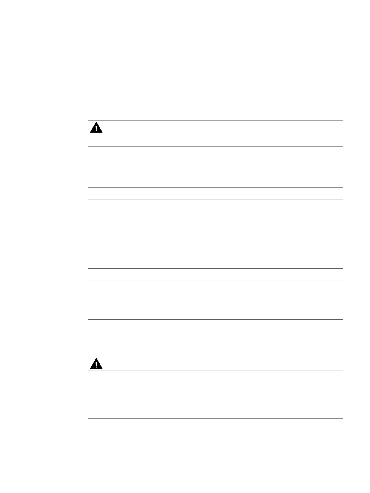
PN/M-Bus LINK is a communication gateway and enables the connection of SIMATIC
controllers to the M-Bus fieldbus via PROFINET. It enables data and information exchange
between PROFINET and M-Bus.
Figure 3-1 SIMATIC PN/M-Bus LINK
PN/M-Bus LINK
10 Operating Instructions, 03/2018, A5E44260928-AA

System overview
3.2
Features
General features
M-Bus features
3.2 Features
● 1 M-Bus connector (3-pin screw-type terminal).
● The device supports baud rates between 300 and 9600 baud.
● Communication with the individual slaves in the M-Bus network can be performed with
different baud rates.
● The PN/M-Bus LINK can be used in the line, star and tree network topologies.
● PN/M-Bus LINK is always the M-Bus master. The M-Bus master reads the measurement
data from the M-Bus slaves and supplies the M-Bus with power.
● You can connect up to 40 M-Bus slaves to the M-Bus network (standard loads with
current consumption < 1.5 mA). If the current consumption of individual M-Bus slaves is
more than a standard load, fewer M-Bus slaves can be connected.
● When an M-Bus slave is in a short-circuit state, the PN/M-Bus LINK can still communicate
with other M-Bus slaves.
● PN/M-Bus LINK supports the "Primary address" and "Secondary address" addressing
modes.
● 2 PROFINET interfaces (integrated switch) enable PROFINET line operation according to
Conformance Class B (CC-B).
● PN/M-Bus LINK is configured in the TIA Portal via a GSDML file.
Implemented M-Bus functions:
● SND_NKE: Establish communication with M-Bus slave
● REQ_UD2: Request data from slave
● SND_UD: Enables addressing over secondary address
PN/M-Bus LINK
Operating Instructions, 03/2018, A5E44260928-AA
11
System overview
3.3
System configuration
System configuration
Purpose and function of the system components
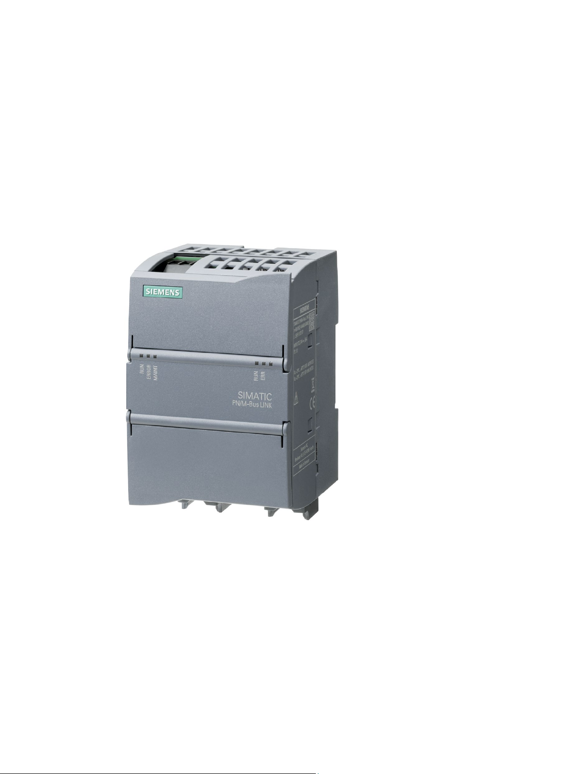
3.3 System configuration
The following figure shows a basic system configuration with PN/M-Bus LINK as a
communication gateway between a PROFINET network and an M-Bus network.
Figure 3-2 System configuration with PN/M-Bus LINK
PN/M-Bus LINK enables the connection of the M-Bus to PROFINET.
PN/M-Bus LINK communicates with the CPU of the S7 controller exclusively via the
PROFINET interface.
From a PROFINET point of view, PN/M-Bus LINK is an IO device according to Conformance
Class B (CC-B).
Cyclic data exchange between the PN/M-Bus LINK and the connected SIMATIC-CPU is
performed by updating the IO image. Acyclic communication is handled via the "Read Data
Record" service.
The power is supplied to the PN/M-Bus LINK either via an external power supply unit with
24 V DC or via the 24 V power supply of the SIMATIC S7 system.
The TIA Portal is used for configuring. A GSDML file is available for this purpose.
PN/M-Bus LINK
12 Operating Instructions, 03/2018, A5E44260928-AA

System overview
3.4
System requirements
System requirements
3.4 System requirements
● PN/M-Bus LINK
● Controller: Supported are SIMATIC S7-1200, SIMATIC S7-1500, SIMATIC ET 200SP,
SIMATIC OpenController
● 24 V power supply
● M-Bus network
● PROFINET bus
● Windows PC (for configuring, commissioning and diagnostics)
● TIA Portal V15
● We recommend a switch for configuring, commissioning and diagnostics.
PN/M-Bus LINK
Operating Instructions, 03/2018, A5E44260928-AA
13
System overview
3.5
Design
PN/M-BUS LINK setup
Design
grounding
②
uses on PROFINET
for PROFINET
PROFINET (X1P2)
⑥
PROFINET (X1P1)
state
⑨
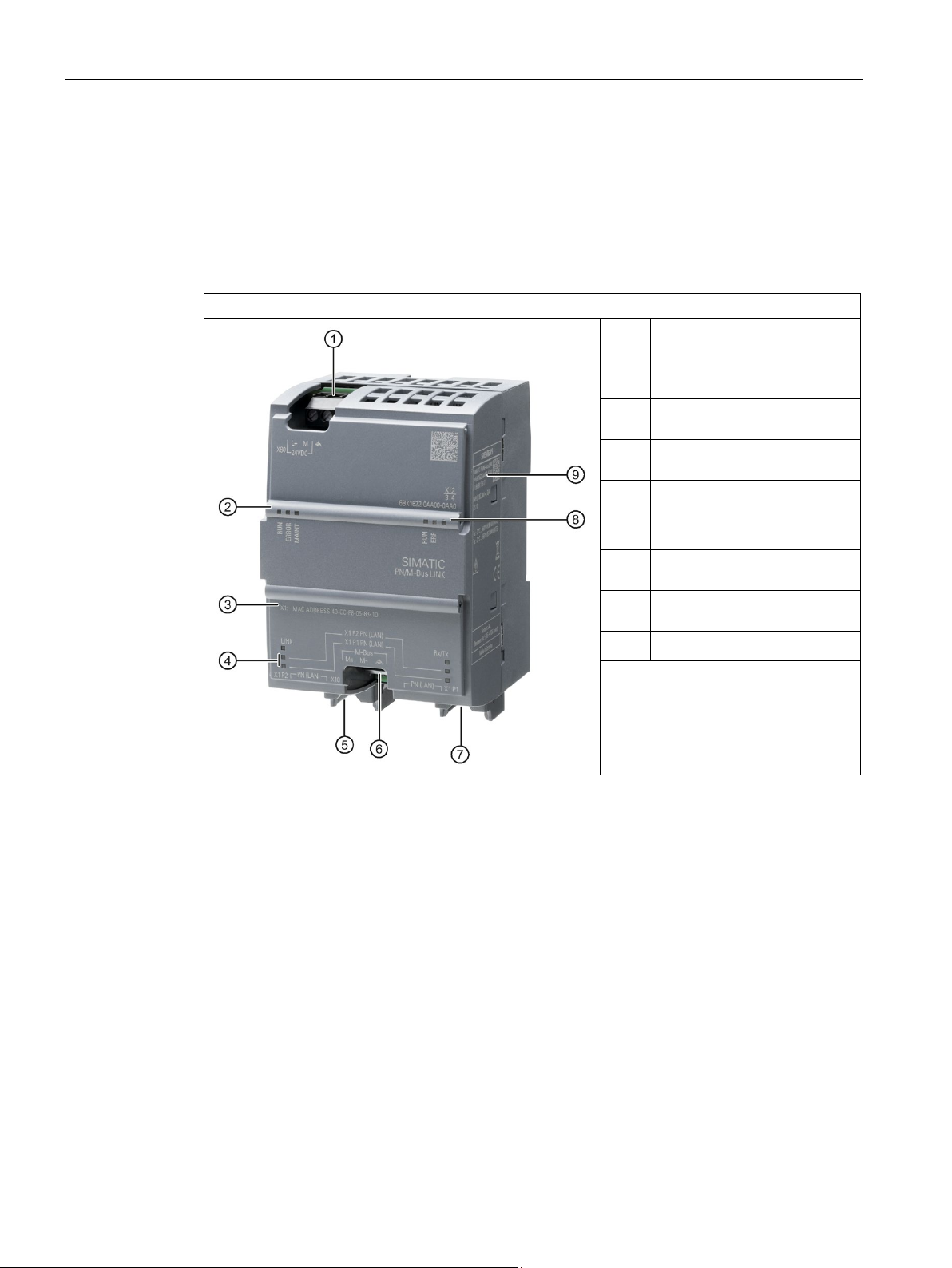
3.5 Design
The following figure shows the arrangement of the connection and display elements on
PN/M-Bus LINK. The figure shows the device without a top and bottom enclosure cover.
①
③
④
⑤
⑦
⑧
24 V DC + functional
Status LEDs device operating
state + PROFINET
MAC address that the device
Status LEDs Ethernet interface
Ethernet connection for
Connection for M-Bus
Ethernet connection for
Status LEDs, M-Bus operating
Rating plate
PN/M-Bus LINK
14 Operating Instructions, 03/2018, A5E44260928-AA
4
4.1
Cyclic and acyclic data exchange
Communication paths
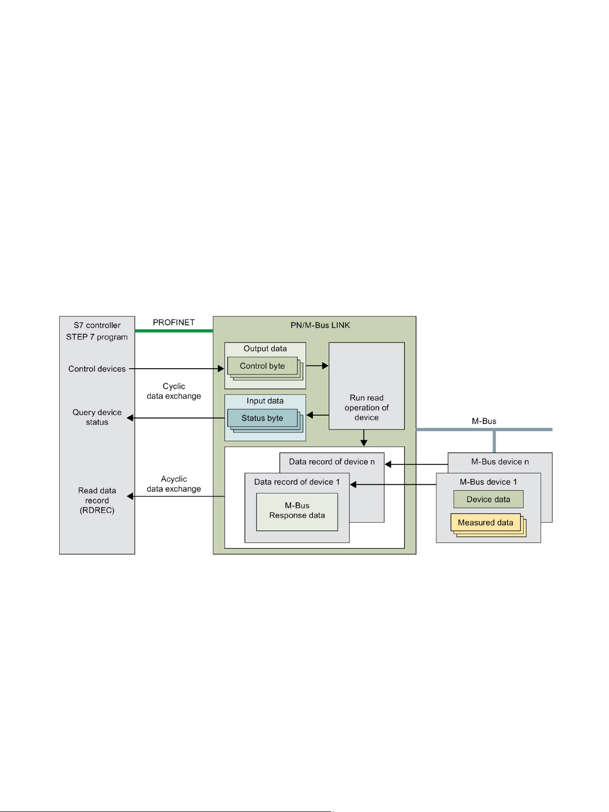
PN/M-Bus LINK is always the M-Bus master. The functions of the PN/M-Bus LINK enable
you to read measured data from connected M-Bus devices. To do this, the M-Bus functions
"SND_NKE", "SND_UD" and "REQ_UD2" are implemented in PN/M-Bus LINK. It is not
possible to configure or write to M-Bus devices.
The following figure shows the interrelationships in the communication between the
S7 controller, PN/M-Bus LINK and connected M-Bus devices.
Figure 4-1 Communication paths between S7 controller, PN/M-Bus LINK and M-Bus devices
PN/M-Bus LINK
Operating Instructions, 03/2018, A5E44260928-AA
15

Functions
Cyclic data exchange: Control and status information
Bit
Meaning
Value
0
No action
M-Bus device
1 ... 7
Not used
--
--
Bit
Meaning
Value
1
Read operation in progress
0
No error occurred during last read operation
1
Error occurred during last read operation
2 ... 7
Not used
--
--
4.1 Cyclic and acyclic data exchange
The transmission of control and status information between the S7 controller and
PN/M-Bus LINK is performed via the cyclic IO process image.
In order to read measurement data from a specific M-Bus device, the S7 user program sets
the control bit for the respective M-Bus slave in the cyclic output data from the value "0" to
the value "1".
Table 4- 1 Cyclic output data (Byte 0)
0 Control bit for read request
1 Read request to read measured data from
If the PN/M-Bus LINK accepts the call, it sets the corresponding status bit in the cyclic input
data from "0" to "1". After the PN/M-Bus LINK has read the measurement data from the
addressed M-Bus device, it sets the corresponding status bit in the cyclic input data
from "1" to "0".
If an error occurs during a read attempt, the PN/M-Bus LINK also sets the corresponding
status bit to "0" but sets the error bit at the same time. In this case, the data record does not
contain measured values.
Table 4- 2 Cyclic input data (Byte 0)
0 Status bit for read request 0 Device inactive
1 Error bit for feedback of the read
operation
PN/M-Bus LINK
16 Operating Instructions, 03/2018, A5E44260928-AA

Functions
Acyclic data exchange: Reading measurement data from M-Bus devices
Byte
Name
Data type
Value
Description
UINT16
Device error information
1
No data available
structure
CI1 = 72h/76h
CI1 = 73h/77h
bytes
starting with the first DIF (EN1434-3)
1) CI field (control information field) from received RSP_UD response telegram
4.1 Cyclic and acyclic data exchange
The measured values are transferred from the PN/M-Bus LINK to the S7 control system
through data records. The PN/M-Bus LINK always reads all available measured values from
an M-Bus device and saves the measured values as a data record.
A data record is read via "Read Data Record" (RDREC). The default index number is 600.
A data record contains the user data from the RSP_UD response telegram with the
transmitted measured values, starting with the first DIF. The telegram header is not included
in the data record.
The data block with the measured data contained in the data record is transferred to the
S7 controller without any changes. The corresponding evaluation and further processing of
the measurement data must be performed by the user program.
A data record has the following structure:
0 … 1 ResponseCode
0 No error
2 M-Bus communication error - no data
available
2 … 3 Mode UINT16 Specification of the M-Bus data
0 Variable data structure
1 Fixed data structure
4 … 5 Length UINT16 Total length of the M-Bus STRUCT in
6 … <END> Measured data M-Bus STRUCT Measured data from M-Bus device,
PN/M-Bus LINK
Operating Instructions, 03/2018, A5E44260928-AA
17
 Loading...