

Siemens SIMATIC PN/J1939 LINK Operating Instructions Manual
SIEMENS


___________________
___________________
___________________
___________________
___________________
___________________
___________________
___________________
___________________
___________________
___________________
___________________
SIMATIC
Gateways
SIMATIC PN/J1939 LINK
Operating Instructions
12/2018
A5E45307564
Introduction
1
Safety instructions
2
System overview
3
Functions
4
Application planning
5
Mounting/Extending
6
Connecting
7
Commissioning
8
Configuring / programming
9
Diagnostics
10
Maintenance and service
11
Technical specifications
12
Appendix
A
-AA

Siemens AG
Division Digital Factory
Post
90026 NÜRNBERG
GERMANY
A5E45307564-AA
Ⓟ
Copyright © Siemens AG 2017 - 2018.
All rights reserved
Legal information
Warning notice system
DANGER
indicates that death or severe personal injury will result if proper precautions are not taken.
WARNING
indicates that death or severe personal injury may result if proper precautions are not taken.
CAUTION
indicates that minor personal injury can result if proper precautions are not taken.
NOTICE
indicates that property damage can result if proper precautions are not taken.
Qualified Personnel
personnel qualified
Proper use of Siemens products
WARNING
Siemens products may only be used for the applications described in the catalog and in the relevant technical
ambient conditions must be complied with. The information in the relevant documentation must be observed.
Trademarks
Disclaimer of Liability
This manual contains notices you have to observe in order to ensure your personal safety, as well as to prevent
damage to property. The notices referring to your personal safety are highlighted in the manual by a safety alert
symbol, notices referring only to property damage have no safety alert symbol. These notices shown below are
graded according to the degree of danger.
If more than one degree of danger is present, the warning notice representing the highest degree of danger will
be used. A notice warning of injury to persons with a safety alert symbol may also include a warning relating to
property damage.
The product/system described in this documentation may be operated only by
task in accordance with the relevant documentation, in particular its warning notices and safety instructions.
Qualified personnel are those who, based on their training and experience, are capable of identifying risks and
avoiding potential hazards when working with these products/systems.
Note the following:
documentation. If products and components from other manufacturers are used, these must be recommended
or approved by Siemens. Proper transport, storage, installation, assembly, commissioning, operation and
maintenance are required to ensure that the products operate safely and without any problems. The permissible
All names identified by ® are registered trademarks of Siemens AG. The remaining trademarks in this publication
may be trademarks whose use by third parties for their own purposes could violate the rights of the owner.
We have reviewed the contents of this publication to ensure consistency with the hardware and software
described. Since variance cannot be precluded entirely, we cannot guarantee full consistency. However, the
information in this publication is reviewed regularly and any necessary corrections are included in subsequent
editions.
for the specific
fach 48 48
12/2018 Subject to change

Table of contents
1 Introduction ............................................................................................................................................. 5
2 Safety instructions ................................................................................................................................... 7
3 System overview ................................................................................................................................... 11
4 Functions .............................................................................................................................................. 15
5 Application planning .............................................................................................................................. 27
6 Mounting/Extending .............................................................................................................................. 33
7 Connecting ........................................................................................................................................... 35
1.1 Preface ...................................................................................................................................... 5
1.2 Documentation guide ................................................................................................................ 6
2.1 Safety instructions ..................................................................................................................... 7
2.2 Security information .................................................................................................................. 9
2.3 Protective measures for SIMATIC PN/J1939 LINK .................................................................. 9
3.1 Field of application .................................................................................................................. 11
3.2 Features .................................................................................................................................. 12
3.3 System configuration .............................................................................................................. 13
3.4 System requirements .............................................................................................................. 14
3.5 Design ..................................................................................................................................... 14
4.1 J1939 protocol ........................................................................................................................ 15
4.2 PGN parameters ..................................................................................................................... 19
4.3 Cyclic and acyclic data exchange ........................................................................................... 22
4.4 State model ............................................................................................................................. 23
4.5 Control and status information ................................................................................................ 25
4.6 Response to errors ................................................................................................................. 26
5.1 Installation guidelines.............................................................................................................. 27
5.2 Installation location ................................................................................................................. 28
5.3 Transportation ......................................................................................................................... 30
5.4 Storage ................................................................................................................................... 30
5.5 Scope of delivery .................................................................................................................... 31
6.1 Installing the device ................................................................................................................ 33
7.1 Safety instructions and guidelines .......................................................................................... 35
7.2 Potential ratios ........................................................................................................................ 37
SIMATIC PN/J1939 LINK
Operating Instructions, 12/2018, A5E45307564-AA
3

Table of contents
8 Commissioning ..................................................................................................................................... 43
9 Configuring / programming .................................................................................................................... 45
10 Diagnostics ........................................................................................................................................... 53
11 Maintenance and service ...................................................................................................................... 61
12 Technical specifications ........................................................................................................................ 63
A Appendix .............................................................................................................................................. 69
Glossary ............................................................................................................................................... 73
Index .................................................................................................................................................... 75
7.3 24 V DC power supply ........................................................................................................... 38
7.4 Connecting the functional ground .......................................................................................... 39
7.5 Connecting PROFINET .......................................................................................................... 40
7.6 Connecting the J1939 bus ..................................................................................................... 41
8.1 Commissioning PN/J1939 LINK ............................................................................................. 43
9.1 Overview ................................................................................................................................ 45
9.2 Devices & networks ............................................................................................................... 45
9.3 PN/J1939 LINK assign parameters........................................................................................ 47
9.4 Insert and configure parameter groups .................................................................................. 48
9.5 Checking and compiling the configuration ............................................................................. 51
10.1 Status LEDs ........................................................................................................................... 53
10.1.1 Operating state of the PN/J1939 LINK / PROFINET diagnostics .......................................... 53
10.1.2 Connection status of the Ethernet interfaces ......................................................................... 55
10.1.3 Connection status of the J1939 bus ...................................................................................... 56
10.2 Diagnostic messages to the S7 controller ............................................................................. 57
10.2.1 Events that trigger a diagnostic message .............................................................................. 57
10.2.2 Diagnostic messages ............................................................................................................. 58
11.1 Firmware update .................................................................................................................... 61
11.2 Replacing PN/J1939 LINK ..................................................................................................... 61
11.3 Recycling and disposal .......................................................................................................... 62
12.1 Technical specifications of the PN/J1939 LINK ..................................................................... 63
12.2 Dimension drawing ................................................................................................................ 67
A.1 Certificates and approvals ..................................................................................................... 69
A.2 Contact address ..................................................................................................................... 70
A.3 Licenses ................................................................................................................................. 70
A.4 Service & Support .................................................................................................................. 71
A.4.1 Technical Support .................................................................................................................. 71
A.4.2 Siemens Industry Online Support .......................................................................................... 71
A.4.3 Online catalog and ordering system ...................................................................................... 71
SIMATIC PN/J1939 LINK
4 Operating Instructions, 12/2018, A5E45307564-AA

1
1.1
Preface
Purpose of this documentation
Knowledge required
Trademarks
History
Edition
Note
Naming conventions
These operating instructions contain all information for configuring, installation,
commissioning and operation of the PN/J1939 LINK.
These operating instructions are intended for qualified personnel in the following target
groups:
● Commissioning engineers
● Operating and service personnel
● System integrator
The following knowledge is required in order to understand the operating instructions:
● Knowledge of programming a SIMATIC S7 controller
● Knowledge in the application of the TIA configuration environment
● Knowledge of working with the PROFINET fieldbus
● Well-founded knowledge in the SAE J1939 communication protocol
● General knowledge in the field of automation technology
● General knowledge of communication networks
SIMATIC® is a registered trademark of Siemens AG.
12/2018 First edition
The term "PN/J1939 LINK" or "device" is used in this documentation instead of the full
product name "SIMATIC PN/J1939 LINK".
The term "S7 controller", or "S7" for short, is also used for the SIMATIC S7 controller.
SIMATIC PN/J1939 LINK
Operating Instructions, 12/2018, A5E45307564-AA
5

Introduction
1.2
Documentation guide
Additional documentation
Subject
Documentation
Most important contents
1.2 Documentation guide
Below you will find a list of documents which supplement these operating instructions for the
PN/J1939 LINK and which are available on the Internet.
Designing interference-free
controllers
PROFINET SIMATIC PROFINET System De-
Function Manual Designing interference-free controllers
(https://support.industry.siemens.c
om/cs/ww/en/view/59193566)
scription
(https://support.industry.siemens.c
om/cs/ww/en/view/19292127)
• Basics
• Electromagnetic compatibility
• Lightning protection
• Basics
• Installation
• Functions
• Configuration examples
The latest manuals for SIMATIC products are available for download free of charge from the
Internet (https://support.industry.siemens.com/cs/ww/en/ps/man).
The information system in the TIA Portal also supports you in configuring and programming
your automation system as well as the PN/J1939 LINK.
SIMATIC PN/J1939 LINK
6 Operating Instructions, 12/2018, A5E45307564-AA
2
2.1
Safety instructions
CAUTION
NOTICE
Intended use
NOTICE
Repairs
WARNING
The device contains no user-serviceable parts.
May cause death or serious injury
Observe the safety instructions on the inside front cover of this documentation.
SIMATIC PN/J1939 LINK devices comply with the approvals printed on the rating plate. If
you have questions about whether it is permissible to install the device in the planned
environment, please contact your service representative.
Alterations to the devices are not permitted.
Failure to observe this requirement shall constitute a revocation of the CE approval and
manufacturer's warranty.
The PN/J1939 LINK may only be used for the applications specified in the catalog and the
associated technical documentation. If the device is used in a manner other than the one
specified by Siemens, the protection offered by the device might be impaired.
See also the section "Legal notices" at the beginning of this manual.
Unauthorized opening or improperly performed repairs can cause considerable damage to
property and/or danger to users. Contact Siemens Support
(http://support.automation.siemens.com) in case of error.
SIMATIC PN/J1939 LINK
Operating Instructions, 12/2018, A5E45307564-AA
7

Safety instructions
Safety information
WARNING
Connection only over safety extra-low voltage / protective extra-low voltage
May cause death or serious injury
Working on the device or on connected components
WARNING
Risk of electric shock
May cause death or serious injury
2.1 Safety instructions
The device is designed for operation using directly connectable safety extra-low voltage
(SELV) with safe electrical separation according to IEC 60950-1 / EN 60950-1 /
VDE 0805-1 or IEC 61131-2 / EN 61131-2 / DIN EN 61131-2.
To obtain the safe property of low-voltage circuits of the PN/J1939 LINK, the 24 V rated
voltage supply and external connections to communication interfaces must be supplied
from approved sources that meet requirements set forth by various standards for
SELV/PELV voltage-limited sources.
Therefore only connect safety extra-low voltages (SELV) with safe electrical separation
according to IEC 60950-1 / EN 60950-1 / VDE 0805-1 to the supply voltage connections
and the communications interfaces.
• Voltages > 60 V DC or 30 V AC may be present in the control cabinet. Therefore
appropriate safety precautions must be taken to prevent contact during commissioning
and maintenance work.
• Before carrying out any work on the device or on connected components, make sure
that the installation is in a zero-voltage state.
• Use cable types with UL approval for UL-approved systems.
SIMATIC PN/J1939 LINK
8 Operating Instructions, 12/2018, A5E45307564-AA

Safety instructions
2.2
Security information
2.3
Protective measures for SIMATIC PN/J1939 LINK
Protective measures for SIMATIC PN/J1939 LINK
NOTICE
2.2 Security information
Siemens provides products and solutions with industrial security functions that support the
secure operation of plants, systems, machines and networks.
In order to protect plants, systems, machines and networks against cyber threats, it is
necessary to implement – and continuously maintain – a holistic, state-of-the-art industrial
security concept. Siemens’ products and solutions only form one element of such a concept.
Customer is responsible to prevent unauthorized access to its plants, systems, machines
and networks. Systems, machines and components should only be connected to the
enterprise network or the internet if and to the extent necessary and with appropriate security
measures (e.g. use of firewalls and network segmentation) in place.
Additionally, Siemens’ guidance on appropriate security measures should be taken into
account. For more information about industrial security, please visit
(http://www.siemens.com/industrialsecurity).
Siemens’ products and solutions undergo continuous development to make them more
secure. Siemens strongly recommends to apply product updates as soon as available and to
always use the latest product versions. Use of product versions that are no longer supported,
and failure to apply latest updates may increase customer’s exposure to cyber threats.
To stay informed about product updates, subscribe to the Siemens Industrial Security RSS
Feed under (http://www.siemens.com/industrialsecurity).
Only authorized personnel are permitted to access the system and carry out modifications.
SIMATIC PN/J1939 LINK
Operating Instructions, 12/2018, A5E45307564-AA
9

Safety instructions
2.3 Protective measures for SIMATIC PN/J1939 LINK
SIMATIC PN/J1939 LINK
10 Operating Instructions, 12/2018, A5E45307564-AA
3
3.1
Field of application
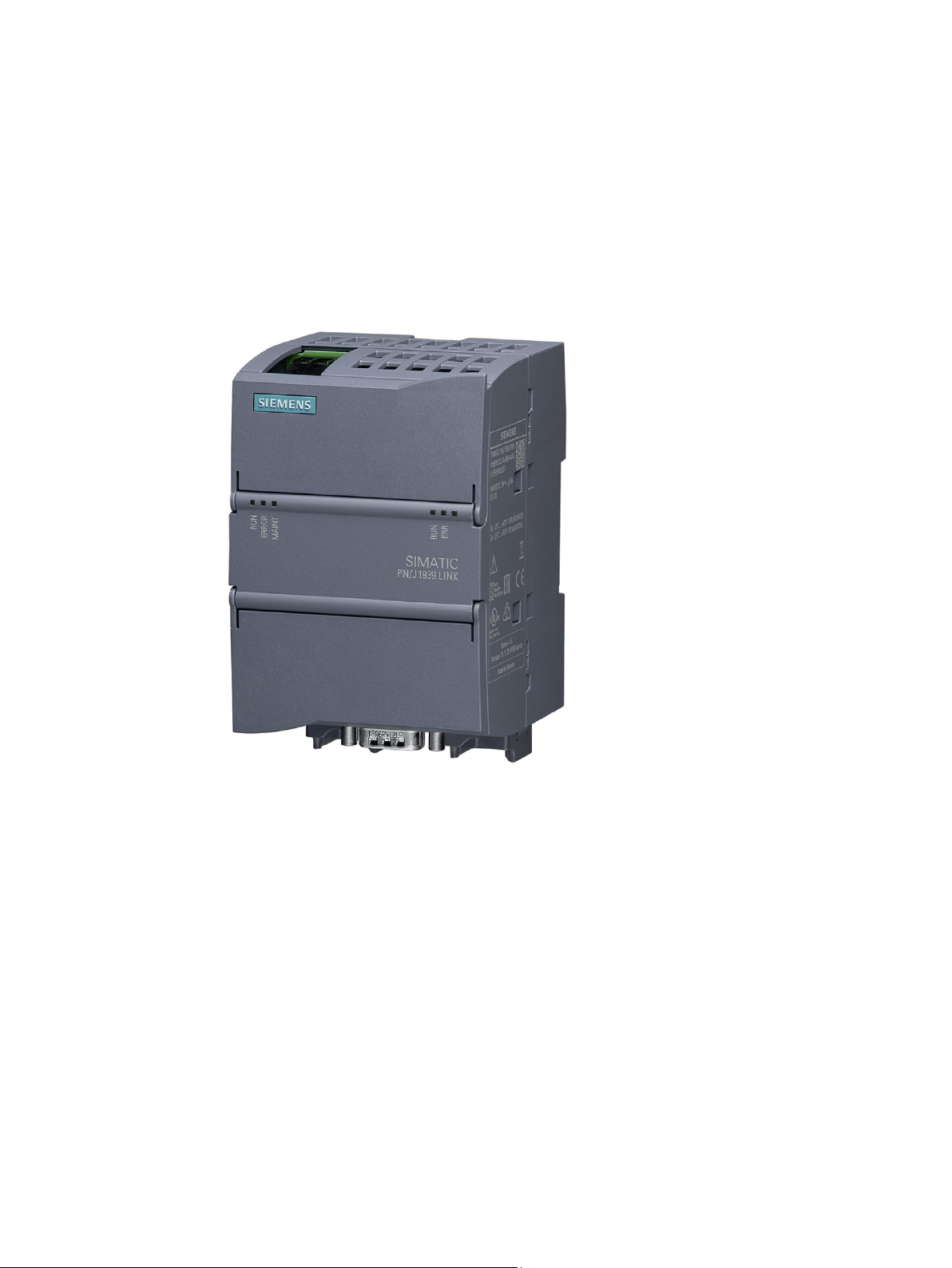
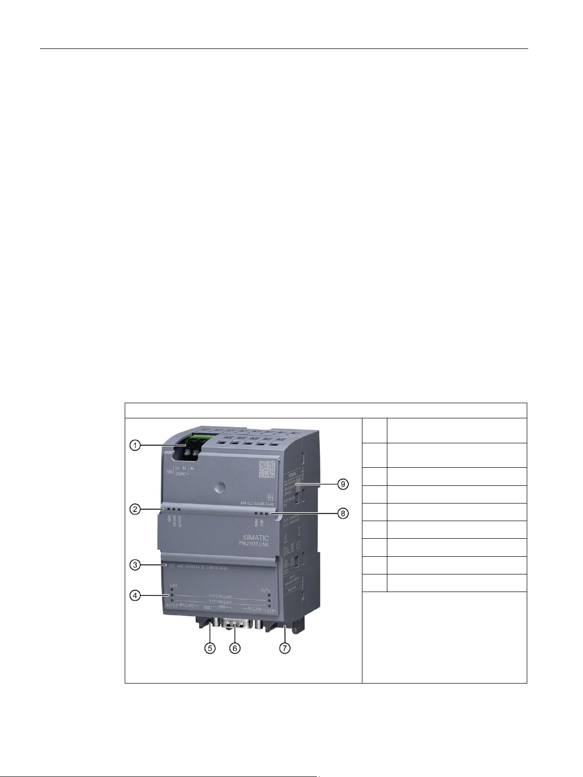
Figure 3-1 SIMATIC PN/J1939 LINK
SIMATIC PN/J1939 LINK is a communication gateway and enables the connection of
SIMATIC controllers to the J1939 network via PROFINET. This allows information and data
to be exchanged between PROFINET and the J1939 network.
SIMATIC PN/J1939 LINK
Operating Instructions, 12/2018, A5E45307564-AA
11

System overview
3.2
Features
General characteristics of PN/J1939 LINK
J1939 features
Configuration limits of the PN/J1939 LINK
Limits specified by PROFINET or the J1939 protocol
3.2 Features
● 1 J1939 connector (CAN, 9-pin D-SUB connector)
● 2 PROFINET interfaces (integrated switch) enable PROFINET line operation according to
Conformance Class B (CC-B).
● The PN/J1939 LINK can be used in the line, star and tree network topologies.
● PN/J1939 LINK is configured in the TIA Portal via a GSDML file.
● Firmware update via SAT (SIMATIC Automation Tool)
● J1939 protocol with physical layer according to ISO 11898-2 (high-speed CAN)
● Implementation according to SAE J1939/11/14 standard
● Transmission rates of 100 Kbps, 250 Kbps and 500 Kbps are supported by the J1939.
● The maximum permissible cable length of the J1939 network is 40 m (depending on data
transmission rate, cable cross-section, number of nodes).
● PN/J1939 LINK represents an Electronic Control Unit (ECU) and contains a Controller
Application (CA)
● PN/J1939 LINK supports "Address Claiming" (ACL)
● PN/J1939 LINK supports the definition of user-specific parameter groups (PGN)
● Peer-to-peer and broadcast communication
● Transport protocol BAM (Broadcast Announce Message) and CMDT (Connection Mode
Data Transfer) for larger volumes of data
● PN/J1939 LINK can read DM1 diagnostic messages from other connected ECUs
● PN/J1939 LINK can write and read parameter groups from the S7 user program.
● PN/J1939 LINK can address up to 30 ECUs in the J1939 network
● PN/J1939 LINK can address up to 253 CAs in the J1939 network
The maximum data length that can be exchanged cyclically via PROFINET is 1440 bytes per
transmission direction. The values that can be achieved with PN/J1939 LINK in practice are
lower and depend on the controller used and the configuration.
The user can send data records acyclically up to a length of 1785 bytes via the S7 program.
Proxy modules with configurable data length are available for this purpose (see Cyclic and
acyclic data exchange (Page 22)). The maximum length of 1785 bytes is specified by the
J1939 protocol.
SIMATIC PN/J1939 LINK
12 Operating Instructions, 12/2018, A5E45307564-AA
System overview
3.3
System configuration
System configuration
Purpose and function of the system components
3.3 System configuration
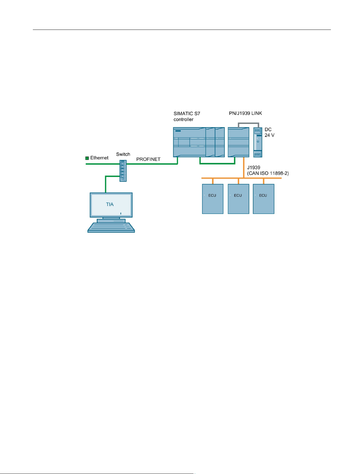
The following figure shows a basic system configuration with a PN/J1939 LINK as a
communication gateway between a PROFINET network and a J1939 network.
Figure 3-2 System configuration with PN/J1939 LINK
PN/J1939 LINK enables PROFINET to be connected to a J1939 network.
Communication of the PN/J1939 LINK with the CPU of the S7 controller takes place
exclusively via the PROFINET interface.
From a PROFINET perspective, the PN/J1939 LINK is an IO device according to
Conformance Class B (CC-B).
From a J1939 perspective, the PN/J1939 LINK is an Electronic Control Unit (ECU) and
contains a Controller Application (CA).
The cyclic data exchange between the PN/J1939 LINK and the connected S7 CPU takes
place via an update of the IO image. Acyclic communication takes place by means of the
"Read data record" and "Write data record" services.
PN/J1939 LINK is powered either via an external 24 V DC power supply unit or via the
24 V power supply of the SIMATIC S7 system.
The TIA Portal is used for configuring. A corresponding GSDML file is available for this
purpose.
SIMATIC PN/J1939 LINK
Operating Instructions, 12/2018, A5E45307564-AA
13
System overview
3.4
System requirements
System requirements
3.5
Design
PN/J1939 LINK design
Design
functional grounding
②
③
④
⑤
⑥
⑦
⑧
⑨
3.4 System requirements
● PN/J1939 LINK
● Only the following controllers are permissible and are supported:
SIMATIC S7-1200, SIMATIC S7-1500, SIMATIC ET 200SP, SIMATIC OpenController
● 24 V voltage supply
● J1939 bus
● PROFINET bus
● Windows PC (for configuring, commissioning and diagnostics)
● TIA Portal as of V14 SP1
● We recommend a switch for configuring, commissioning and diagnostics.
24 V DC connector +
①
Status LEDs device +
PROFINET
MAC address
Status LEDs Ethernet
Ethernet connector (PROFINET)
J1939 connector
Ethernet connector (PROFINET)
Status LEDs J1939
Rating plate
SIMATIC PN/J1939 LINK
14 Operating Instructions, 12/2018, A5E45307564-AA
PN/J1939 LINK design
4
4.1
J1939 protocol
Extended CAN format
Parameter Group Number (PGN)
User-specific PGN
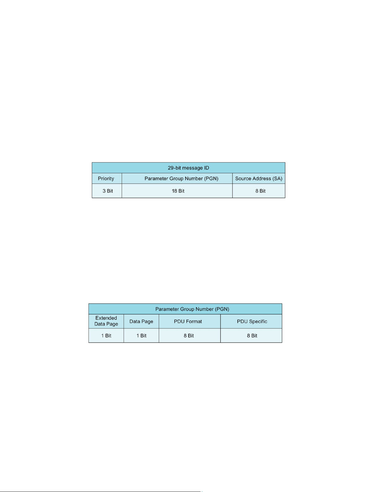
The J1939 protocol uses the Extended CAN Format CAN 2.0B (29-bit message ID).
The 29-bit message ID consists of the following:
Figure 4-1 29-bit message ID
● Message priority. The priority of a message is used for the bus arbitration. The value 0
has the highest priority.
● Parameter Group Number (PGN)
● Address of the device that transmits the message.
A key element of the J1939 protocol is the Parameter Group Number (PGN). The type of a
message can be determined or recognized by means of the PGN.
Figure 4-2 Parameter Group Number (PGN)
Any combination of "PDU Format" and "PDU Specific" parameters is permitted for
configuration in the TIA Portal. Requirement: The combination is within the permissible value
range and not reserved for special purposes.
SIMATIC PN/J1939 LINK
Operating Instructions, 12/2018, A5E45307564-AA
15

Functions
Network address (Source Address)
Address
Meaning
0 to 127
Pre-defined address
248 to 253
Pre-defined address
254
Null address
255
Global address (Broadcast)
J1939 device name (Name Field)
J1939 Name Field
Arbitrary Address Capable
1-bit
Industry Group
3-bit
Vehicle System Instance
4-bit
Vehicle System
7-bit
Reserved
1-bit
Function
8 bit
Function Instance
5-bit
ECU Instance
3-bit
Manufacturer Code
11-bit
Identity Number
21-bit
4.1 J1939 protocol
The address space contains 256 possible network addresses.
128 to 247 Freely available addresses
The address range from 0 to 253 is available for configuring PN/J1939 LINK. See
PN/J1939 LINK assign parameters (Page 47).
The device name is a numeric 64-bit value. The name contains the following information:
● Identification of the device and the device function
● Determines whether the PN/J1939 LINK can select a different network address if it loses
"Address Claiming".
● Priority of the device for "Address Claiming"
The device name is composed as follows:
These parameters or the corresponding device name are configured in the TIA Portal. See
PN/J1939 LINK assign parameters (Page 47).
SIMATIC PN/J1939 LINK
16 Operating Instructions, 12/2018, A5E45307564-AA

Functions
Address claiming
Value
Meaning
Behavior for address claiming
tion and must be configured with a new J1939 network address.
figured in the TIA Portal again.
Peer-to-peer and broadcast communications
4.1 J1939 protocol
Addresses for J1939 devices are assigned using the "Address Claiming" procedure. With
"Address Claiming", each J1939 device sends its desired network address and its J1939
name with PGN 60928. If no other device is using this address, the preferred address can be
used. If the address is already in use, the respective devices compare their names. The
name with the lowest numeric value "wins" the conflict and the corresponding device can use
the address.
With PN/J1939 LINK, you can configure whether the device is able to change its network
address (Arbitrary Address Capable). The parameters are set via the corresponding bit of
the device name:
Table 4- 1 Device name - "Arbitrary Address Capable" field (1-bit)
Bit = 0 PN/J1939 LINK cannot
change its address.
Bit = 1 PN/J1939 LINK can
change its address.
The J1939 protocol makes it possible to send messages either to all subscribers (broadcast)
on the bus or to individual subscribers at specific addresses (peer-to-peer).
If another device claims the same address with a higher priority,
the PN/J1939 LINK performs the following actions:
• PN/J1939 LINK sets its address to 254 (Null address).
• PN/J1939 LINK sends the diagnostics alarm "Invalid ad-
dress" to the S7 controller. See Diagnostic messages
(Page 58).
PN/J1939 LINK can no longer participate in J1939 communica-
If another device claims the same address with a higher priority,
the PN/J1939 LINK performs the following actions:
• PN/J1939 LINK increments its current address.
• PN/J1939 LINK sends the diagnostics alarm "Network ad-
dress changed" to the S7 controller. See Diagnostic messages (Page 58).
PN/J1939 LINK can continue to participate in J1939 communication.
After a restart, PN/J1939 LINK uses the "Source Address" con-
SIMATIC PN/J1939 LINK
Operating Instructions, 12/2018, A5E45307564-AA
17

Functions
Transport protocols
DM messages
4.1 J1939 protocol
Parameter groups with a maximum data length of 8 bytes can be transmitted within a J1939
data packet.
The following transport protocols are available for the transmission of data volumes larger
than 8 bytes.
● BAM (Broadcast Announce Message)
● CMDT (Connection Mode Data Transfer)
BAM messages are sent to all J1939 devices and require no handshaking.
CMDT messages are exchanged peer-to-peer between two J1939 devices. CMDT works
with a handshake method for data flow control.
J1939 ECUs send DM messages to report their active DTCs (Diagnostic Trouble Codes) and
the corresponding lamp status. PN/J1939 LINK can read diagnostic data from the other
connected ECUs. The structure of a DM message corresponds to that of a standard PGN.
Transmission takes place via a multipackage protocol (BAM).
DM1 messages have a PGN (Parameter Group Number) of 65226 and a cycle of 1 second.
If data lengths of up to 512 bytes are sufficient, standard input modules can be used for the
configuration.
For data lengths greater than 512 bytes, configuration takes place via input proxy modules.
The maximum data length is 1785 bytes.
If the PGN 65226 is configured in TIA as an input module with a data length of greater than 8
bytes, a corresponding diagnostics alarm is sent to the S7 controller if there is a change of
the received DM1 data compared to the previous value.
SIMATIC PN/J1939 LINK
18 Operating Instructions, 12/2018, A5E45307564-AA

Functions
4.2
PGN parameters
Parameter name
Module name
Value range
Description
Page
1
messages.
cast).
PGN input proxy
4.2 PGN parameters
The following table gives an overview of the PGN parameters that can be configured in the
TIA Portal via the GSDML file and the meaning of individual parameters. The table also
indicates the PGN modules that have the parameters.
Table 4- 2 PGN parameters
Extended Data
Data Page 0 to 1
PDU Format 0 to 255 The PDU format determines whether the
PDU Specific 0 to 255 The meaning of the field depends on the
CA Source Address
PGN input n bytes
PGN output n bytes
PGN input proxy
PGN output proxy
PGN input n bytes
Extended 0 …
0 to 255 Control Application Source Address -
The "Extended Data Page" and "Data
Page" parameter together use 2 bits of
the PGN. This means that a maximum of
four data pages can be addressed for
message is for a single device or for all
devices.
PDU format < 240:
The message is for a specific device
(Peer-to-peer).
PDU format ≥ 240:
The message is for all devices (Broad-
value in the "PDU format" field.
PDU format < 240:
The value represents the destination
address of the message.
PDU format ≥ 240:
The value is used as group extension.
Network address of the J1939 device
SIMATIC PN/J1939 LINK
Operating Instructions, 12/2018, A5E45307564-AA
19

Functions
Parameter name
Module name
Value range
Description
Highest priority: 0
(BAM) can be sent.
permitted.
allowed.
sage
length
Message
cycle in ms
clic" is configured as send event.
is disabled.
4.2 PGN parameters
Priority PGN output n bytes
PGN output proxy
Transmit event Cyclic PGN is sent with the time interval set in
Transport protocol
Transmission
Priority 0 … 7 Message priority
the "Transmission cycle" parameter. In
"Cyclic" mode, standard messages and
the Broadcast Announce Message
Change of
value
Remote request
Standard mes-
Broadcast
Announce
Connection
Mode Data
Transfer
10 to 5000 Transmission cycle is only valid if "cy-
PGN is sent when the data value
changes. All transport protocols are
PGN is sent when a request is made
from another device in the J1939 network. The request has PGN 59904.
Standard messages and CMDT are
PGN message with up to 8 bytes data
Fragmented transmission of data with
more than 8 bytes without flow control.
Fragmented transmission of data with
more than 8 bytes with flow control.
Reception cycle
in ms
PGN input n bytes
PGN input proxy
0 to 5000 If a PGN is not received in time, a diag-
nostics alarm is sent to the S7 controller.
The value 0 means that the functionality
SIMATIC PN/J1939 LINK
20 Operating Instructions, 12/2018, A5E45307564-AA

Functions
Parameter name
Module name
Value range
Description
bytes are truncated.
index 0x220.
4.2 PGN parameters
PGN data length PGN input n bytes
PGN output n bytes
PGN input proxy 8 to 1785 Specification of the maximum PGN
PGN output proxy Specification of the maximum PGN
8 to 512 PGN modules with specified data
lengths from 8 bytes to a maximum of
512 bytes are available.
If the value for the PGN data length
differs from the maximum module data
length, the difference in bytes is truncated from the PGN message.
Example:
You want to send 20 bytes of data. For
this purpose, you select a PGN output
module with a predefined size of 32
bytes. You specify 20 bytes as the PGN
data length.
Only these 20 bytes are transferred via
the CAN network. The remaining 12
message length. The corresponding
data must be read with the data record
message length. The corresponding
data must be written with the data record
index 0x230.
SIMATIC PN/J1939 LINK
Operating Instructions, 12/2018, A5E45307564-AA
21
Functions
4.3
Cyclic and acyclic data exchange
Communication paths
Cyclic data exchange: Parameter groups (PGN)
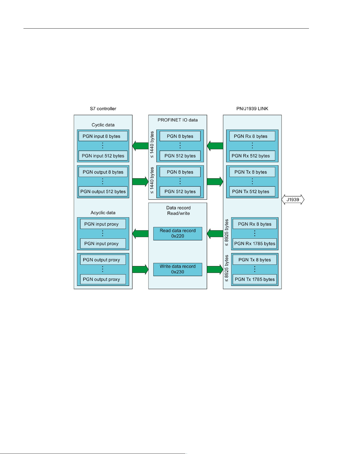
4.3 Cyclic and acyclic data exchange
The following figure shows the relationships in the communication between S7 controller,
PN/J1939 LINK and J1939 bus.
Figure 4-3 Communication paths between S7 controller, PN/J1939 LINK and J1939 bus
The PGN configured via the GSDML file are transmitted cyclically as PROFINET data
between the S7 controller and PN/J1939 LINK. These modules with cyclic data transmission
are referred to as PGN modules in the configuration. For information on the possible data
length, see section Features (Page 12).
You can find information on configuring the PGN modules in the TIA Portal in the section
Configuring / programming (Page 45).
SIMATIC PN/J1939 LINK
22 Operating Instructions, 12/2018, A5E45307564-AA
 Loading...