

Siemens SIMATIC PN/BACnet LINK Operating Instructions Manual

___________________
___________________
___________________
___________________
___________________
___________________
___________________
___________________
___________________
___________________
___________________
___________________
___________________
SIMATIC
Network transitions
PN/BACnet LINK
Operating Instructions
10/2017
A5E39895543
Introduction
1
Safety instructions
2
System overview
3
Functions
4
Application planning
5
Mounting/Extending
6
Connecting
7
Commissioning
8
Configuring / Programming
9
Diagnostics
10
Maintenance and service
11
Technical specifications
12
Appendix
A
-AA

Siemens AG
Division Digital Factory
Postfach 48 48
90026 NÜRNBERG
GERMANY
A5E39895543-AA
Ⓟ
Copyright © Siemens AG 2017.
All rights reserved
Legal information
Warning notice system
DANGER
indicates that death or severe personal injury will result if proper precautions are not taken.
WARNING
indicates that death or severe personal injury may result if proper precautions are not taken.
CAUTION
indicates that minor personal injury can result if proper precautions are not taken.
NOTICE
indicates that property damage can result if proper precautions are not taken.
Qualified Personnel
personnel qualified
Proper use of Siemens products
WARNING
Siemens products may only be used for the applications described in the catalog and in the relevant technical
maintenance are required to ensure that the products operate safely and without any problems. The permissible
ambient conditions must be complied with. The information in the relevant documentation must be observed.
Trademarks
Disclaimer of Liability
This manual contains notices you have to observe in order to ensure your personal safety, as well as to prevent
damage to property. The notices referring to your personal safety are highlighted in the manual by a safety alert
symbol, notices referring only to property damage have no safety alert symbol. These notices shown below are
graded according to the degree of danger.
If more than one degree of danger is present, the warning notice representing the highest degree of danger will
be used. A notice warning of injury to persons with a safety alert symbol may also include a warning relating to
property damage.
The product/system described in this documentation may be operated only by
task in accordance with the relevant documentation, in particular its warning notices and safety instructions.
Qualified personnel are those who, based on their training and experience, are capable of identifying risks and
avoiding potential hazards when working with these products/systems.
Note the following:
documentation. If products and components from other manufacturers are used, these must be recommended
or approved by Siemens. Proper transport, storage, installation, assembly, commissioning, operation and
All names identified by ® are registered trademarks of Siemens AG. The remaining trademarks in this publication
may be trademarks whose use by third parties for their own purposes could violate the rights of the owner.
We have reviewed the contents of this publication to ensure consistency with the hardware and software
described. Since variance cannot be precluded entirely, we cannot guarantee full consistency. However, the
information in this publication is reviewed regularly and any necessary corrections are included in subsequent
editions.
for the specific
11/2017 Subject to change

Table of contents
1 Introduction ............................................................................................................................................. 7
2 Safety instructions................................................................................................................................... 9
3 System overview ................................................................................................................................... 12
4 Functions .............................................................................................................................................. 18
1.1 Preface ..................................................................................................................................... 7
1.2 Documentation guide ............................................................................................................... 8
2.1 Safety instructions .................................................................................................................... 9
2.2 Security information ............................................................................................................... 11
2.3 IT security ............................................................................................................................... 11
3.1 Field of application ................................................................................................................. 12
3.2 Features ................................................................................................................................. 13
3.3 System configuration ............................................................................................................. 15
3.4 System requirements ............................................................................................................. 16
3.5 Design .................................................................................................................................... 17
4.1 BACnet objects ...................................................................................................................... 18
4.1.1 Overview ................................................................................................................................ 18
4.1.2 Server objects ........................................................................................................................ 21
4.1.2.1 Device object .......................................................................................................................... 22
4.1.2.2 Binary input ............................................................................................................................ 23
4.1.2.3 Binary output .......................................................................................................................... 24
4.1.2.4 Analog input ........................................................................................................................... 25
4.1.2.5 Analog output ......................................................................................................................... 26
4.1.3 Client object references ......................................................................................................... 27
4.1.4 Supported BACnet services (BIBB) ....................................................................................... 28
4.2 State model ............................................................................................................................ 29
4.3 Cyclic data exchange between controller and PN/BACnet LINK ........................................... 32
4.3.1 Data exchange between controller and PN/BACnet LINK ..................................................... 32
4.4 Data exchange between PN/BACnet LINK and other BACnet devices................................. 36
4.4.1 Data transfer as client ............................................................................................................ 36
4.4.2 Data transfer as server .......................................................................................................... 37
4.5 Acyclic data exchange ........................................................................................................... 38
4.5.1 Acyclic reading and writing of properties of BACnet objects from the S7 user program ....... 38
4.6 Monitoring functions ............................................................................................................... 42
4.7 Response to errors ................................................................................................................ 43
PN/BACnet LINK
4 Operating Instructions, 10/2017, A5E39895543-AA

Table of contents
5 Application planning .............................................................................................................................. 45
6 Mounting/Extending .............................................................................................................................. 50
7 Connecting ........................................................................................................................................... 52
8 Commissioning ..................................................................................................................................... 59
9 Configuring / Programming ................................................................................................................... 60
10 Diagnostics ........................................................................................................................................... 77
5.1 Installation guidelines.............................................................................................................. 45
5.2 Installation location ................................................................................................................. 46
5.3 Transportation ......................................................................................................................... 49
5.4 Storage ................................................................................................................................... 49
5.5 Scope of delivery .................................................................................................................... 49
6.1 Installing the device ................................................................................................................ 50
7.1 Safety instructions and guidelines .......................................................................................... 52
7.2 Potential ratios ........................................................................................................................ 54
7.3 24 V DC power supply ............................................................................................................ 55
7.4 Connecting the functional ground ........................................................................................... 56
7.5 Connecting PROFINET........................................................................................................... 57
7.6 Connecting BACnet bus ......................................................................................................... 58
8.1 Commissioning the PN/BACnet LINK ..................................................................................... 59
9.1 Overview ................................................................................................................................. 60
9.2 TIA Portal Devices & Networks ............................................................................................... 61
9.3 Configuring the BACnet/IP interface ....................................................................................... 62
9.4 Configuring a BACnet server .................................................................................................. 63
9.5 Configure BACnet client.......................................................................................................... 66
9.5.1 Set client-specific parameters ................................................................................................. 66
9.5.2 Configuring references to BACnet devices ............................................................................. 68
9.5.2.1 Import EDE file ........................................................................................................................ 69
9.5.2.2 Find BACnet device ................................................................................................................ 71
9.5.2.3 Creating object references manually ...................................................................................... 72
9.6 Checking and compiling the configuration .............................................................................. 75
9.7 Programming .......................................................................................................................... 75
9.7.1 PLC tags ................................................................................................................................. 75
10.1 Status LEDs ............................................................................................................................ 77
10.1.1 Operating state of the PN/BACnet LINK / PROFINET diagnostics ........................................ 77
10.1.2 Connection status BACnet bus ............................................................................................... 79
10.1.3 Connection status of Ethernet interfaces ................................................................................ 80
10.2 Diagnostic messages to the S7 controller .............................................................................. 81
10.2.1 Events that trigger a diagnostic message ............................................................................... 81
PN/BACnet LINK
Operating Instructions, 10/2017, A5E39895543-AA
5

Table of contents
11 Maintenance and service ...................................................................................................................... 84
12 Technical specifications ........................................................................................................................ 86
A Appendix .............................................................................................................................................. 90
Glossary ............................................................................................................................................... 93
Index .................................................................................................................................................... 95
11.1 Firmware update .................................................................................................................... 84
11.2 Reset to factory settings ........................................................................................................ 84
11.3 Replacing the PN/BACnet LINK ............................................................................................. 85
11.4 Recycling and disposal .......................................................................................................... 85
12.1 Technical specifications ......................................................................................................... 86
12.2 Dimension drawing ................................................................................................................ 89
A.1 Certificates and approvals ..................................................................................................... 90
A.2 Contact address ..................................................................................................................... 91
A.3 Licenses ................................................................................................................................. 91
A.4 Service & Support .................................................................................................................. 92
A.4.1 Technical Support .................................................................................................................. 92
A.4.2 Siemens Industry Online Support .......................................................................................... 92
A.4.3 Online catalog and ordering system ...................................................................................... 92
PN/BACnet LINK
6 Operating Instructions, 10/2017, A5E39895543-AA

1
1.1
Preface
Purpose of this documentation
Knowledge required
Trademarks
History
Edition
Remarks
These operating instructions contain all the information required for configuring, installing,
commissioning and operating the PN/BACnet LINK.
These operating instructions are intended for qualified personnel in the following target
groups:
● Commissioning engineers
● Operating and service personnel
● System integrator
The following knowledge is required in order to understand the operating instructions:
● Knowledge of programming a SIMATIC S7 controller
● Knowledge in the application of the TIA configuration environment
● Knowledge of working with the PROFINET fieldbus
● Sound knowledge of the BACnet/IP communication protocol
● General knowledge in the field of automation technology
● General knowledge of communication networks
SIMATIC® is a registered trademark of Siemens AG.
10/2017 First edition
PN/BACnet LINK
Operating Instructions, 10/2017, A5E39895543-AA
7

Introduction
Naming conventions
1.2
Documentation guide
Additional documentation
Subject
Documentation
Most important contents
1.2 Documentation guide
The following terms are also used in this documentation instead of the full product name
"SIMATIC PN/BACnet LINK":
● "PN/BACnet LINK"
● "Device"
Below you will find a list of documents which supplement these operating instructions for the
PN/BACnet LINK and which are available on the Internet.
Designing interference-free controllers
PROFINET SIMATIC PROFINET System Description
Function Manual Designing interference-free
controllers
(https://support.industry.siemens.com/cs/ww/de/vi
ew/59193566)
(https://support.industry.siemens.com/cs/ww/de/vi
ew/19292127)
• Basics
• Electromagnetic
compatibility
• Lightning protection
• Basics
• Installation
• Functions
• Configuration examples
The latest manuals for SIMATIC products are available for download free of charge from the
Internet (https://support.industry.siemens.com/cs/ww/de/ps/man).
The information system of the TIA Portal also helps you configure and program your
automation system and the PN/BACnet LINK.
PN/BACnet LINK
8 Operating Instructions, 10/2017, A5E39895543-AA
2
2.1
Safety instructions
CAUTION
NOTICE
Intended use
NOTICE
Repairs
WARNING
The device contains no user-serviceable parts.
May cause death or serious injury
Observe the safety instructions on the inside front cover of this documentation.
SIMATIC PN//BACnet LINK devices correspond to the approvals printed on the type plate. If
you have questions about whether it is permissible to install the device in the planned
environment, please contact your service representative.
Alterations to the devices are not permitted.
Failure to observe this requirement shall constitute a revocation of the CE approval and
manufacturer's warranty.
The PN/BACnet LINK may only be used for the applications described in the catalog and in
the associated technical documentation. If the device is used in a manner other than the
one specified by Siemens, the protection offered by the device might be impaired.
See also the section "Legal notices" at the beginning of this manual.
Unauthorized opening or improperly performed repairs can cause considerable damage to
property and/or danger to users. Contact Siemens Support
(http://support.automation.siemens.com) in case of error.
PN/BACnet LINK
Operating Instructions, 10/2017, A5E39895543-AA
9

Safety instructions
Safety information
WARNING
Connection only over safety extra-low voltage / protective extra-low voltage
May cause death or serious injury
Working on the device or on connected components
WARNING
Risk of electric shock
May cause death or serious injury
2.1 Safety instructions
The device is designed for operation using directly connectable safety extra-low voltage
(SELV) with safe electrical separation according to IEC 60950-1 / EN 60950-1 /
VDE 0805-1 or IEC 61131-2 / EN 61131-2 / DIN EN 61131-2.
To maintain the safety property of the low voltage circuits of the PN/BACnet LINK, the 24 V
rated power supply as well as external connections to communication ports must be
supplied from reliable sources that meet the requirements for SELV / PELV limited voltage
sources according to different standards.
Therefore only connect safety extra-low voltages (SELV) with safe electrical separation
according to IEC 60950-1 / EN 60950-1 / VDE 0805-1 to the supply voltage connections
and the communications interfaces.
• Voltages > 60 V DC or 30 V AC may be present in the control cabinet. Therefore
appropriate safety precautions must be taken to prevent contact during commissioning
and maintenance work.
• Before carrying out any work on the device or on connected components, make sure
that the installation is in a zero-voltage state.
• Use cable types with UL approval for UL-approved systems.
PN/BACnet LINK
10 Operating Instructions, 10/2017, A5E39895543-AA

Safety instructions
2.2
Security information
2.3
IT security
Protective measures for SIMATIC PN/BACnet LINK
NOTICE
2.2 Security information
Siemens provides products and solutions with industrial security functions that support the
secure operation of plants, systems, machines and networks.
In order to protect plants, systems, machines and networks against cyber threats, it is
necessary to implement – and continuously maintain – a holistic, state-of-the-art industrial
security concept. Siemens’ products and solutions only form one element of such a concept.
Customer is responsible to prevent unauthorized access to its plants, systems, machines
and networks. Systems, machines and components should only be connected to the
enterprise network or the internet if and to the extent necessary and with appropriate security
measures (e.g. use of firewalls and network segmentation) in place.
Additionally, Siemens’ guidance on appropriate security measures should be taken into
account. For more information about industrial security, please visit
(http://www.siemens.com/industrialsecurity).
Siemens’ products and solutions undergo continuous development to make them more
secure. Siemens strongly recommends to apply product updates as soon as available and to
always use the latest product versions. Use of product versions that are no longer supported,
and failure to apply latest updates may increase customer’s exposure to cyber threats.
To stay informed about product updates, subscribe to the Siemens Industrial Security RSS
Feed under (http://www.siemens.com/industrialsecurity).
Only authorized personnel are permitted to access the system and carry out modifications.
PN/BACnet LINK
Operating Instructions, 10/2017, A5E39895543-AA
11
3
3.1
Field of application
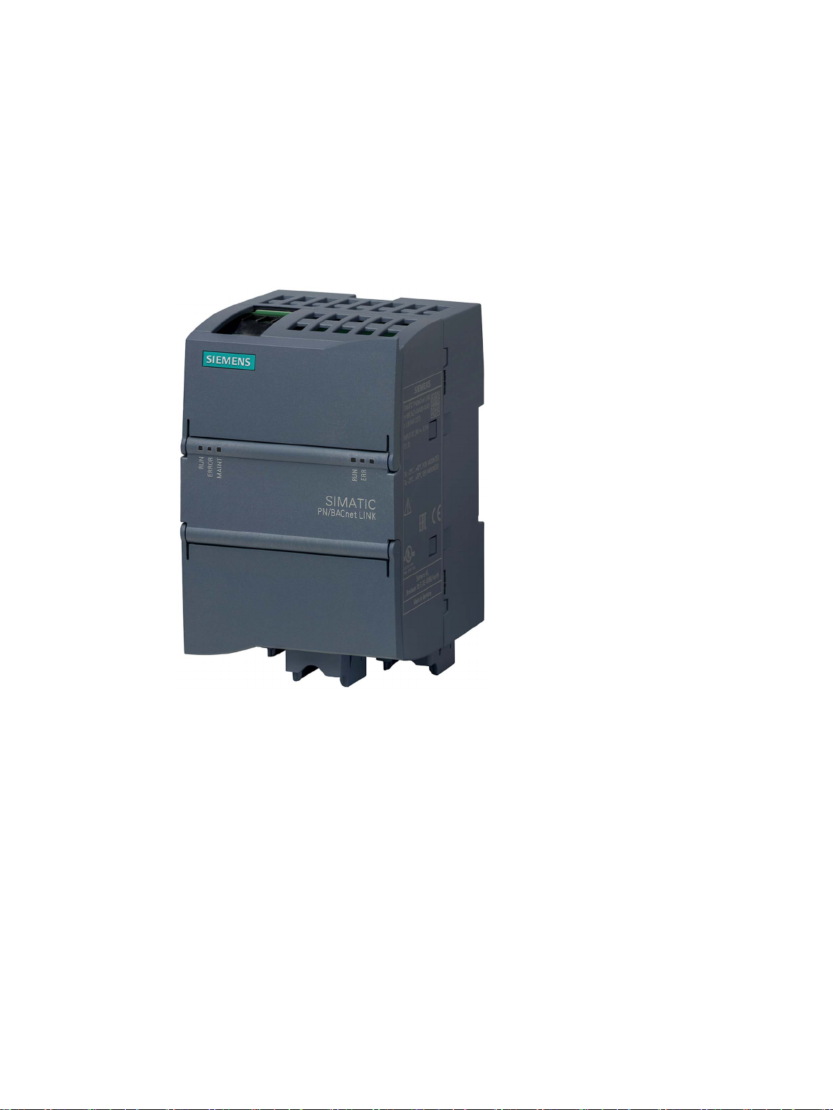
Figure 3-1 SIMATIC PN/BACnet LINK
The PN/BACnet LINK is a communication gateway and enables the connection of SIMATIC
controllers to the BACnet/IP fieldbus over PROFINET. This connection enables the
exchange of information and data between PROFINET and BACnet/IP.
PN/BACnet LINK
12 Operating Instructions, 10/2017, A5E39895543-AA

System overview
3.2
Features
General features
BACnet characteristics
3.2 Features
● 1 BACnet port (Fast Ethernet, RJ45). The maximum transmission rate is 100 Mbps.
● The PN/BACnet LINK supports BACnet/IP according to DIN EN ISO16484-5 and
Addendum ANSI/ASHRAE Standard 135-2012.
● BACnet/IP profile: B-GW (BACnet gateway)
● 2 PROFINET interfaces (integrated switch) enable PROFINET line operation according to
Conformance Class B (CC-B).
● A PN/BACnet LINK can be both a BACnet client and a BACnet server. The actual
functionality of the PN/BACnet LINK is defined when it is configured. A mixed mode of
Client and Server functionality is possible.
● The PN/BACnet LINK is configured via the corresponding HSP in the TIA Portal.
● The following options are available for creating BACnet object references:
– Manual input of the required object addresses
– Scanning the network with takeover of the selected objects
– Import a network description (EDE file) and select the desired objects
● The BACnet server located in the PN/BACnet LINK can handle up to 1000 subscribers.
● The BACnet client located in the PB/BACnet LINK can establish communication
relationships with up to 126 BACnet devices.
Supported BACnet object types:
● DEVICE
● BINARY INPUT
● BINARY OUTPUT
● ANALOG INPUT
● ANALOG OUTPUT
Supported BACnet services:
● Change of Value COV-A/B
● ReadProperty RP-A/B
● WriteProperty WP-A/B
Monitoring of BACnet devices:
● Cyclic query of the status properties in the device object
● Set the status in the device object of the PN/BACnet LINK
PN/BACnet LINK
Operating Instructions, 10/2017, A5E39895543-AA
13

System overview
Quantity structure for configuring the PN/BACnet LINK
Limits specified by the PN/BACnet LINK
Limits caused by the system configuration as well as communication over PROFINET
Object type
Server
Object reference
PII
PIQ
PII
PIQ
Binary input (BI)
-- 1 1
--
Binary output (BO)
1 1 1
1
Analog output (AO)
4 1 1
4
3.2 Features
● The sum of all server objects and the object references on the BACnet devices must not
exceed 1000 (e.g. 400 binary inputs on the server and 600 referenced binary outputs).
● Maximum of 400 server objects.
● Maximum of 126 BACnet devices.
● Maximum of 204 analog inputs or 255 analog outputs on the server
● Maximum of 204 analog inputs or 256 analog outputs on the client
When using multiple BACnet clients or mixing client object references and server objects,
the maximum user data length in the PROFINET frame of 1280 bytes is relevant as an
additional criterion. The user data length is exhausted in both directions, for example,
through 255 analog output on the server side plus 255 referenced analog outputs plus
3 binary outputs on the server and client side.
Depending on the PROFINET cycle, the following amount of data can be transferred:
● For a maximum of 1000 binary inputs or binary outputs total or
● For a maximum of 510 analog inputs or analog outputs (no more than 255 per
transmission direction) or
● Combinations of the items listed above
Data bytes required in the frame depending on object type:
Analog input (AI) --- 5 5 --
When using the PN/BACnet LINK on a S7-1200 controller, there is an additional limitation
given by the size of the process image of the CPU. A total of no more than 204 analog
entries is possible here.
PN/BACnet LINK
14 Operating Instructions, 10/2017, A5E39895543-AA
System overview
3.3
System configuration
System configuration
Purpose and function of the system components
3.3 System configuration
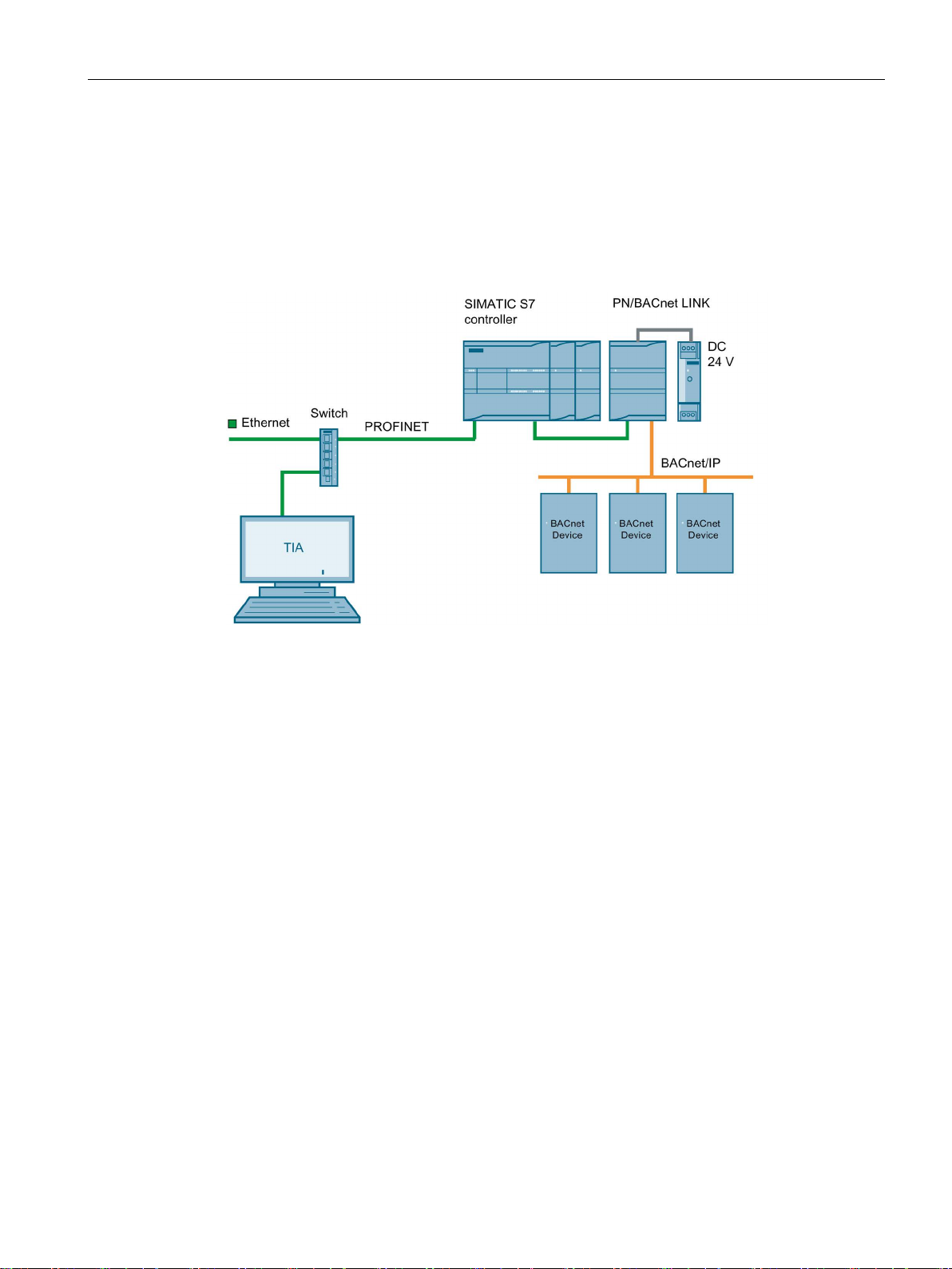
The following figure shows a basic system configuration with a PN/BACnet LINK as a
communication gateway between a PROFINET network and a BACnet/IP network.
Figure 3-2 System configuration with PN/BACnet LINK
The PN/BACnet LINK enables the connection of PROFINET to BACnet/IP.
The communication of the PN/BACnet LINK with the CPU of the S7 controller takes place
exclusively over the PROFINET interface.
From the PROFINET view, the PN/BACnet LINK is an IO device according to Conformance
Class B (CC-B).
The cyclic data exchange between the PN/BACnet LINK and the connected SIMATIC CPUs
is based on updating the IO image. Acyclic communication takes place by means of "Read
data record" and "Write data record" services.
Power is supplied to the PN/BACnet LINK either via an external 24 V DC power supply or via
the 24 V power supply of the SIMATIC S7 system.
The TIA Portal is used for configuring. A corresponding HSP is available for this purpose.
PN/BACnet LINK
Operating Instructions, 10/2017, A5E39895543-AA
15

System overview
3.4
System requirements
System requirements
3.4 System requirements
● PN/BACnet LINK
● Controller: Supported are SIMATIC S7-1200, SIMATIC S7-1500, SIMATIC ET 200SP,
SIMATIC OpenController
● 24 V power supply
● BACnet/IP bus
● PROFINET bus
● Windows PC (for configuring, commissioning and diagnostics)
● TIA Portal V14 SP1 (at least with Update 2)
● We recommend a switch for configuring, commissioning and diagnostics.
PN/BACnet LINK
16 Operating Instructions, 10/2017, A5E39895543-AA
System overview
3.5
Design
PN/BACnet LINK design
Design
①
state + PROFINET
③
uses on BACnet
for BACnet
⑤
PROFINET
⑦
⑧
⑨
See also
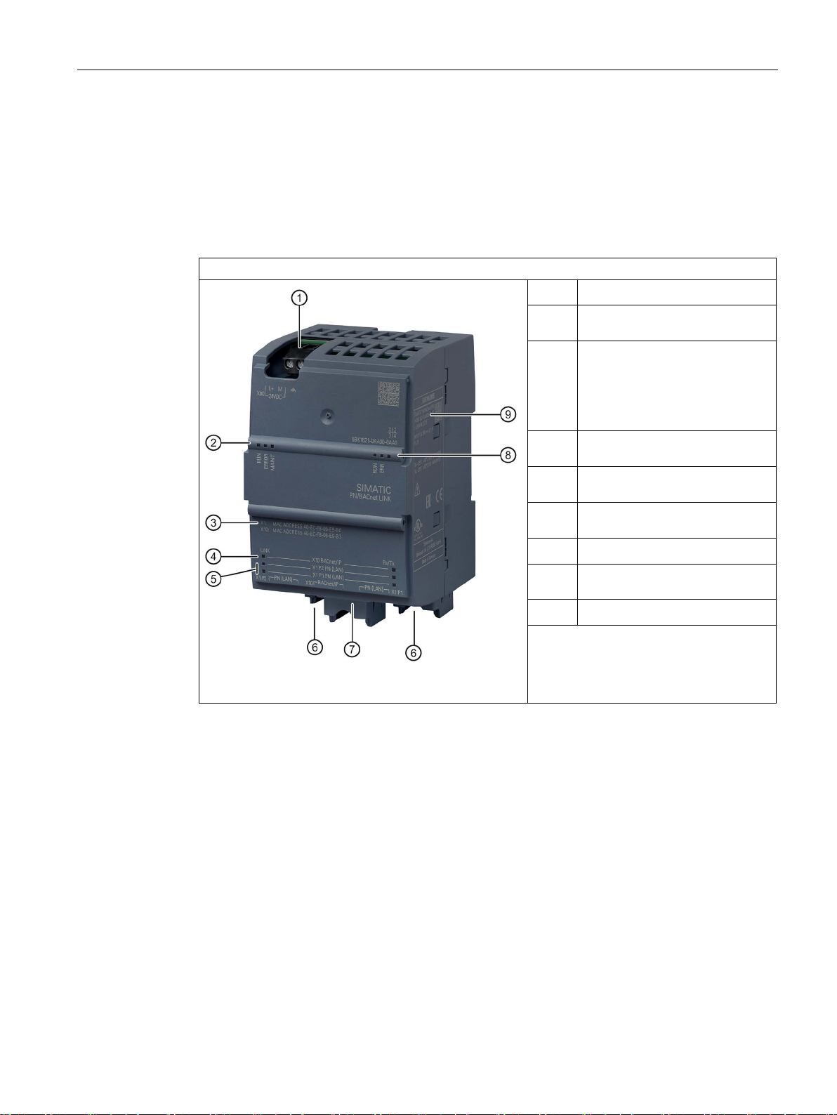
3.5 Design
The figure below shows the arrangement of the connection and display elements on the
PN/BACnet LINK. The figure shows the device without a top and bottom enclosure cover.
24 V DC + functional grounding
②
Status LEDs device operating
MAC addresses
X1: Address that the device uses
on PROFINET
X10: Address that the device
PN/BACnet LINK design
24 V DC power supply (Page 55)
Connecting PROFINET (Page 57)
Connecting BACnet bus (Page 58)
Status LEDs (Page 77)
④
⑥
Status LEDs Ethernet interface
Status LEDs Ethernet interface
for PROFINET
Ethernet connections for
Ethernet connection for BACnet
Status LEDs BACnet operating
state
Rating plate
PN/BACnet LINK
Operating Instructions, 10/2017, A5E39895543-AA
17

4
4.1
BACnet objects
4.1.1
Overview
Server objects and Client object references
The PN/BACnet LINK can be used both as a BACnet client and as a BACnet server. As a
client, PN/BACnet LINK is the active communication partner, that is, it requests data from
other communication partners (BACnet servers). As a server, PN/BACnet LINK provides
data that is used by other communication users (BACnet clients). A mixed mode of Client
and Server functionality is possible.
When describing objects, a distinction is made between Server objects and Client object
references. Server objects are full BACnet objects which the PN/BACnet LINK makes
available for other BACnet devices (Clients). Client object references are references to
Server objects which are located in other BACnet devices (Servers).
PN/BACnet LINK
18 Operating Instructions, 10/2017, A5E39895543-AA
Functions
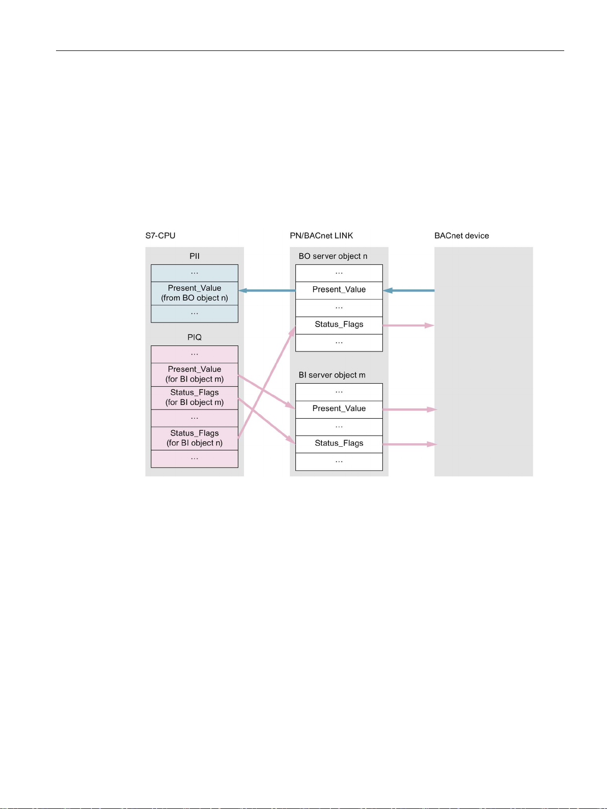
Communication paths of BACnet server
4.1 BACnet objects
BACnet objects of the type "Binary input (BI) and "Analog input" (AI) are inputs on the
BACnet side. The values are written from the S7 side to the "Present_Value" property of the
corresponding input object.
BACnet objects of the type "Binary output (BO) and "Analog output" (AO) are outputs on the
BACnet side. The "Present_Value" properties of the output objects are read from the
S7 side.
With server objects, the PN/BACnet LINK writes the status information transferred by the
S7 controller to the property "Status_Flags" of the corresponding objects.
Figure 4-1 Communication paths of BACnet server
PN/BACnet LINK
Operating Instructions, 10/2017, A5E39895543-AA
19

Functions
Communication paths of BACnet client
4.1 BACnet objects
The PN/BACnet LINK reads the values of the corresponding "Present_Value" properties and
transfers them to the S7 controller via references to input objects. The PN/BACnet LINK
writes values which come from the S7 controller to the associated "Present_Value"
properties of the corresponding objects via references to output objects.
The "Status_Flags" are transferred to the S7 controller as input data. With "Status_Flags",
transmission is always from the object to which the reference is pointing, to the S7 controller,
independent of the type of object.
Figure 4-2 Communication paths of BACnet client
PN/BACnet LINK
20 Operating Instructions, 10/2017, A5E39895543-AA

Functions
4.1.2
Server objects
4.1 BACnet objects
Server objects are BACnet objects which the PN/BACnet LINK contains itself. When they are
configured, full BACnet objects are written with the required properties.
The PN/BACnet LINK supports the following Server objects:
● Device
● Binary input
● Binary output
● Analog input
● Analog output
The following describes which of the associated properties are implemented in the individual
server objects. The entries in the corresponding tables have the following meaning:
● All values which are filled from the data source "Configuration" are defined by the user or
the HSP as part of configuring.
● For "fixed" values, the corresponding fixed assignments are found in the tables. These
values cannot be changed.
● The entry "Dynamic" means: The Property value results from current operating
conditions. The value can change dynamically.
● The "Access" column indicates whether read (R) and/or write access (W) to properties of
the BACnet object is possible.
PN/BACnet LINK
Operating Instructions, 10/2017, A5E39895543-AA
21

Functions
4.1.2.1
Device object
Device object properties
Property
Data source
Value
Access
Object_Identifier
Configuration
--
R
Object_Name
Configuration
--
R
Object_Type
Fixed 8 R
Vendor_Name
Fixed
Siemens AG
R
Vendor_Identifier
Fixed 7 R
Model_Name
Fixed
PN/BACnet LINK
R
xxxx = 4-digit build number
Application_Software_Version
Configuration
--
R
Protocol_Version
Fixed 1 R
Protocol_Revision
Fixed
13 R Protocol_Services_Supported
Dynamic
--
R
Protocol_Object_Types_Supported
Dynamic
--
R
Object_List
Dynamic
--
R
Max_APDU_Length_Accepted
Fixed
1476
R
Segmentation_Supported
Fixed
0 = SEGMENTED_BOTH
R
APDU_Timeout
Fixed
6000 (= 6 s)
R
Number_Of_APDU_Retries
Fixed 3 R
Device_Address_Binding
Dynamic
-- R Database_Revision
Configuration
--
R
Active_COV_Subscriptions
Dynamic
-- R Apdu segment timeout
Fixed
5000 (= 5 s)
R
Max_Segments_Accepted
Fixed
32
R
R: Read
4.1 BACnet objects
Every BACnet device object and also therefore the PN/BACnet LINK has a device object as
logical representation of the device. This object specifies the basic properties of a BACnet
device. Devices in the BACnet network can read out the properties of a BACnet device. For
example, as a BACnet client, the PN/BACnet LINK is able to read the device object from
other devices in the BACnet network.
The following table shows which properties are supported for the device object of the
PN/BACnet LINK and from which source the associated values originate.
System_Status Dynamic -- R
Firmware_Revision Fixed e.g. V1.0.0-xxxx
R
PN/BACnet LINK
22 Operating Instructions, 10/2017, A5E39895543-AA
Description Configuration -- R

Functions
Note
The device object must be configured even if only client object references are required, since
this object must be present in every BACnet device.
4.1.2.2
Binary input
Binary input properties
Property
Data source
Value
Access
Object_Identifier
Configuration
R
Object_Name
Configuration
R Object_Type
Fixed
always "3"
R
Present_Value
Dynamic R(W)
Status_Flags
Dynamic R
Event_State
Fixed
always NORMAL
R
Out_Of_Service
Dynamic R/W
Polarity
Fixed
always NORMAL
R
Description
Configuration
R
R: Read
W: Write
4.1 BACnet objects
All the properties listed in the table can only be read from the BACnet side. Writing of these
properties from the BACnet side is not possible.
The PN/BACnet LINK supports the object type "Binary input" as server. BACnet objects of
the type "Binary input" are inputs on the BACnet side. They are written from the S7 side.
The following table shows which properties are supported for this object type of the
PN/BACnet LINK and from which data source the associated values are filled.
The "Present_Value" property can only be written when the "Out_of_Service" property has
the value TRUE.
The property "Out_Of_Service" can be read and written from the BACnet side.
All the other properties listed in the table can only be read from the BACnet side.
PN/BACnet LINK
Operating Instructions, 10/2017, A5E39895543-AA
23

Functions
4.1.2.3
Binary output
Binary output properties
Property
Data source
Value
Access
Object_Identifier
Configuration
R
Object_Name
Configuration
R
Object_Type
Fixed
always "4"
R
Status_Flags
Dynamic R
Event_State
Fixed
always NORMAL
R
Out_Of_Service
Dynamic R/W
Polarity
Fixed
always NORMAL
R
Priority_Array
Dynamic R
Relinquish_Default
Configuration
R
Description
Configuration
R
R: Read
W: Write
4.1 BACnet objects
The PN/BACnet LINK supports the object type "Binary output" as server. BACnet objects of
the type "Binary output" are outputs on the BACnet side. They are read from the S7 side.
The following table shows which properties are supported for the object type "Binary output"
of the PN/BACnet LINK and from which data source the associated values are filled.
Present_Value Dynamic R/W
The "Present_Value" and "Out_Of_Service" properties can be read from the BACnet page
and also written to it.
All the other properties listed in the table can only be read from the BACnet side.
PN/BACnet LINK
24 Operating Instructions, 10/2017, A5E39895543-AA

Functions
4.1.2.4
Analog input
Analog input properties
Property
Data source
Value
Access
Object_Identifier
Configuration
R
Object_Name
Configuration
R
Object_Type
Fixed
always "0"
R
Status_Flags
Dynamic R
Event_State
Fixed
always NORMAL
R
Out_Of_Service
Dynamic R/W
Units
Configuration
R
COV_Increment
Configuration
R
Description
Configuration
R
R: Read
W: Write
Note
With a COV increment of 0, the value of "Present_Value" is constantly transmitted even if it
does not change.
4.1 BACnet objects
The PN/BACnet LINK supports the object type "Analog input" as server. BACnet objects of
the type "Analog input" are inputs on the BACnet side. They are written from the S7 side.
The following table shows which properties are supported for this object type of the
PN/BACnet LINK and from which source the associated values are filled.
Present_Value Dynamic R(W)
The "Present_Value" property can only be written when the "Out_of_Service" property has
the value TRUE.
The property "Out_Of_Service" can be read and written from the BACnet side.
All the other properties listed in the table can only be read from the BACnet side.
PN/BACnet LINK
Operating Instructions, 10/2017, A5E39895543-AA
25

Functions
4.1.2.5
Analog output
Analog output properties
Property
Data source
Value
Access
Object_Identifier
Configuration
R
Object_Name
Configuration
R
Object_Type
Fixed
always "1"
R
Status_Flags
Dynamic R
Event_State
Fixed
always NORMAL
R
Out_Of_Service
Dynamic R/W
Units
Configuration
R
Priority_Array
Dynamic R
Relinquish_Default
Configuration
R
COV_Increment
Configuration
R Description
Configuration
R
R: Read
W: Write
Note
With a COV increment of 0, the value of "Present_Value" is constantly transmitted even if i
does not change.
4.1 BACnet objects
The PN/BACnet LINK supports the object type "Analog output" as server. BACnet objects of
the type "Analog output" are outputs on the BACnet side. They are read from the S7 side.
The following table shows which properties are supported for this object type of the
PN/BACnet LINK and from which source the associated values are filled.
Present_Value Dynamic R/W
The properties "Present_Value" and "Out_Of_Service" can be read and also written from the
BACnet side. All the other properties listed in the table can only be read from the BACnet
side.
t
PN/BACnet LINK
26 Operating Instructions, 10/2017, A5E39895543-AA

Functions
4.1.3
Client object references
Supported object references
4.1 BACnet objects
Client object references are references to BACnet objects which are located in other BACnet
devices.
If the PN/BACnet LINK does not require any server objects, which means only client object
references are configured, the device object must still be configured.
The PN/BACnet LINK supports object references to the following BACnet objects:
● Binary input
● Binary output
● Analog input
● Analog output
The supported object references are defined on configuration of the PN/BACnet LINK.
When configuring, the following should be specified:
● To which BACnet object on which BACnet device the client object reference in the
PN/BACnet LINK is referring to.
● How access to this object is handled
PN/BACnet LINK
Operating Instructions, 10/2017, A5E39895543-AA
27

Functions
4.1.4
Supported BACnet services (BIBB)
Supported BIBB
BIBB
Description
this.
nite lifetime for a COV subscription.
ning a BACnet network.
"I-Am" answer.
"I-Have" answer.
LINK requires this BIBB to be able to read properties from these objects.
quests which are received from other BACnet devices in the PN/BACnet LINK.
jects.
quests which are received from other BACnet devices in the PN/BACnet LINK.
are supported.
4.1 BACnet objects
DS-COV-A The PN/BACnet LINK works as a Client and is able to register with other objects
for notification when a value changes. The service "SubscribeCOV" is used for
DS-COV-B The PN/BACnet LINK works as a Server and responds to "SubscribeCOV"
packages which are received from other BACnet devices in the PN/BACnet
LINK. Notification of these devices if a value changes is performed via the service "ConfirmedCOVNotification" or "UnconfirmedCOVNotification". The service
used depends on the parameters contained in the received "SubscribeCOV"
package.
Note: The server functionality of the PN/BACnet LINK does not support an infi-
DM-DDB-A The PN/BACnet LINK works as a Client and is able to request the identification
of other BACnet devices via the service "Who-Is". This service is used for scan-
DM-DDB-B The PN/BACnet LINK works as a Server and responds to "Who-Is" requests
which are received from other BACnet devices in the PN/BACnet LINK with an
DM-DOB-B The PN/BACnet LINK works as a Server and responds to "Who-Has" requests
which are received from other BACnet devices in the PN/BACnet LINK with an
DS-RP-A With configured Client object references to input objects (BI, AI), the PN/BACnet
DS-RP-B The PN/BACnet LINK works as a Server and responds to "ReadProperty" re-
DS-WP-A With configured Client object references to output objects (BO, AO), the
PN/BACnet LINK requires this BIBB to be able to write properties to these ob-
DS-WP-B The PN/BACnet LINK works as a Server and responds to "WriteProperty" re-
GW-EO-B The PN/BACnet LINK assumes the representation of the S7 controller in the
BACnet network. The object types listed in the section Server objects (Page 21)
PN/BACnet LINK
28 Operating Instructions, 10/2017, A5E39895543-AA

Functions
4.2
State model
Controlling the server and client status
Client functionality
Server functionality
Value of control byte
Reaction
4.2 State model
The configuration made in HSP is transmitted to the PB/BACnet LINK in the startup phase of
the S7 controller. This configuration information is stored in the S7 controller and not in the
PN/BACnet LINK.
The data transfer is controlled via a control byte (Page 32) which is transmitted cyclically by
the S7 controller to the PN/BACnet LINK as part of the I/O data.
If the bit for controlling the client functionality is set to OFF, the I/O data is not transmitted
between the PN/BACnet LINK and the BACnet network. Transmission is only activated when
the control bit is set to ON.
The system status in the device object is controlled via a control byte (Page 32). The S7
controller also transmits this control byte cyclically as part of the I/O data to the PN/BACnet
LINK.
The control byte can contain the following values:
OPERATIONAL
NON_OPERATIONAL
OPERATIONAL_READ_ONLY
• "Out_Of_Service" flags of all server objects are updated.
• "Out_of_Service" property can be written from outside in this
state.
• "Out_Of_Service" flags of all server objects are set to TRUE.
• "SubscribeCOV", "WriteProperty", "ReadProperty" on server
objects are rejected.
• Subscribers using the SubscribeCOV service are notified
(Notification).
• "WriteProperty" is rejected.
• "ReadProperty"/"SubscribeCOV" are accepted.
• "Out_Of_Service" flags of all server objects are still updated.
PN/BACnet LINK
Operating Instructions, 10/2017, A5E39895543-AA
29
 Loading...