

Siemens SIMATIC PG 760 PII User Manual

Preface, Contents
SIMATIC
PG 760 PII
Programming Device
Manual
Product Overview
Unpacking and Setting Up the
PG 760 PII
Installing and Operating the
PG 760 PII
PG 760 PII Expansions
Configuring the PG 760 PII
Error Diagnostics
Hardware Information
Appendices
ESD Guidelines
1
2
3
4
5
6
7
A
C79000-G7076-C766-01
06/98
Glossary, Index

Safety Guidelines
!
!
!
This manual contains notices which you should observe to ensure your own personal safety, as well as to
protect the product and connected equipment. These notices are highlighted in the manual by a warning
triangle and are marked as follows according to the level of danger:
Danger
indicates that death, severe personal injury or substantial property damage will result if proper precautions are
not taken.
Warning
indicates that death, severe personal injury or substantial property damage can result if proper precautions are
not taken.
Caution
indicates that minor personal injury or property damage can result if proper precautions are not taken.
Note
draws your attention to particularly important information on the product, handling the product, or to a particular
part of the documentation.
Qualified Personnel
Correct Usage
The device/system may only be set up and operated in conjunction with this manual.
Only qualified personnel should be allowed to install and work on this equipment. Qualified persons are
defined as persons who are authorized to commission, to ground, and to tag circuits, equipment, and systems in accordance with established safety practices and standards.
Note the following:
Warning
!
Trademarks
The reproduction, transmission or use of this document or its contents is
not permitted without express written authority. Of fenders will be liable for
damages. All rights, including rights created by patent grant or registration
of a utility model or design, are reserved.
Siemens AG
Bereich Automatisierungs- und Antriebstechnik
Geschaeftsgebiet Industrie-Automatisierungssysteme
Postfach 4848, D - 90327 Nuernberg
This device and its components may only be used for the applications described in the catalog or the technical
description, and only in connection with devices or components from other manufacturers which have been
approved or recommended by Siemens.
This product can only function correctly and safely if it is transported, stored, set up, and installed correctly , and
operated and maintained as recommended.
SIMA TIC R, SIMA TIC NETR and SIMATIC HMIR are registered trademarks of SIEMENS AG.
Third parties using for their own purposes any other names in this document which refer to
trademarks might infringe upon the rights of the trademark owners.
Disclaimer of LiabilityCopyright E Siemens AG 1998 All rights reserved
We have checked the contents of this manual for agreement with the
hardware and software described. Since deviations cannot be precluded
entirely , we cannot guarantee full agreement. However , the data in this
manual are reviewed regularly and any necessary corrections included in
subsequent editions. Suggestions for improvement are welcomed.
E Siemens AG 1998
Technical data subject to change.
Siemens Aktiengesellschaft
C79000-G7076-C766
PG 760 PII Programming Device

Preface
What this Manual
is About
Who is the Manual
Intended For?
Validity of the
Manual
This manual contains all the information you need for working with the
PG 760 PII programming device. You can use it to:
S Unpack the programming device and power it up.
S Familiarize yourself with the functions and settings of the various
components (display, keyboard, programming facilities etc.).
S Connect the programming device to other units of equipment
(programmable controllers, other programming devices).
S Expand your system, provided you comply with the necessary conditions.
S Analyze and eliminate simple problems.
The following persons require the manual:
S Users commissioning the programming device themselves or working
with it (editing, programming, debugging).
S System administrators operating the programming device in a network.
S Service and maintenance personnel using the PG 760 PII for system
expansion purposes or error/fault analysis.
This manual describes the version of the PG 760 PII as available from
January 1998. The Product Information Bulletin supplied with the PG 760 PII
contains the latest technical specifications of the programming device.
Licences
Where to Find
Information
PG 760 PII Programming Device
C79000-G7076-C766-01
The approvals, certificates and licenses for your device are supplied along
with the Product Information Bulletin.
Along with your PG 760 PII, you also receive the following documents
which you require for commissioning the device:
S The Product Information Bulletin with the valid technical data of the
PG 760 PII.
S A Product Information leaflet about the software supplied with the
PG 760 PII.
For more detailed information about handling the software, please refer to
the appropriate manuals (for example, the STEP 5 manual).
iii

Preface
Plan of the Text
This manual contains the most important instructions for commissioning and
using the PG 760 PII required in special situations.
Setting up and getting to know your device
Before you start to use your programming device, you should read about
setting up the device in Chapter 2 and about the components and functions of
the PG 760 PII in Chapter 3.
Installation
Chapter 3 describes the basic steps necessary for starting up the PG 760 PII.
This chapter also contains instructions for working with SIMATIC memory
cards and for connecting the programming device to other devices.
Expansion
Chapter 4 describes how to expand your PG 760 PII (for example,
installation of memory expansions). Please observe the safety instructions in
this section.
Configuration
Modifications made to the system hardware may make it necessary for you to
adapt the original hardware configuration. This is described in Chapter 5.
Error/fault diagnostics
Chapter 6 explains how to deal with simple faults and problems that you can
diagnose and, in some cases, eliminate yourself.
Reference data
Chapter 7 contains information about hardware addresses, interrupt
assignments and connecting cables.
Queries
ESD guidelines
The guidelines on the handling of electrostatically sensitive devices are
particularly important for service and maintenance technicians who are
installing expansion units or carrying out error analysis with the PG 760 PII.
Glossary
The glossary defines and explains important terms.
Alphabetical index
The alphabetical index will help you to find passages in the text relating to
important terms quickly and reliably.
If you have any questions concerning subjects not covered in the manual,
simply get in touch with the Siemens representative in your area. The
addresses for the maintenance and repair centers and the SIMATIC hotline
can be found in the Product Information Bulletin.
If you have any questions about the manual itself or would like to make any
suggestions, please complete the remarks form at the end of the manual.
PG 760 PII Programming Device
iv
C79000-G7076-C766-01

Contents
1 Product Overview 1-1. . . . . . . . . . . . . . . . . . . . . . . . . . . . . . . . . . . . . . . . . . . . . . . . . . . . . .
2 Unpacking and Setting Up the PG 760 PII 2-1. . . . . . . . . . . . . . . . . . . . . . . . . . . . . . . .
2.1 Setup and Hardware Components of the PG 760 PII 2-2. . . . . . . . . . . . . . . . .
2.2 Components of the PG 760 PII 2-3. . . . . . . . . . . . . . . . . . . . . . . . . . . . . . . . . . . .
2.3 Keyboard 2-5. . . . . . . . . . . . . . . . . . . . . . . . . . . . . . . . . . . . . . . . . . . . . . . . . . . . . .
2.4 Drives 2-9. . . . . . . . . . . . . . . . . . . . . . . . . . . . . . . . . . . . . . . . . . . . . . . . . . . . . . . . .
2.5 Transport 2-12. . . . . . . . . . . . . . . . . . . . . . . . . . . . . . . . . . . . . . . . . . . . . . . . . . . . . . .
3 Installing and Operating the PG 760 PII 3-1. . . . . . . . . . . . . . . . . . . . . . . . . . . . . . . . . .
3.1 Connecting the PG 760 PII to the Power Supply 3-2. . . . . . . . . . . . . . . . . . . . .
3.2 Connecting I/O Devices 3-4. . . . . . . . . . . . . . . . . . . . . . . . . . . . . . . . . . . . . . . . . .
3.3 Working with SIMATIC Memory Cards 3-7. . . . . . . . . . . . . . . . . . . . . . . . . . . . .
3.4 PG 760 PII Connections (Point-to-Point Connections) 3-8. . . . . . . . . . . . . . . .
3.5 Multipoint Interface (MPI/DP) 3-12. . . . . . . . . . . . . . . . . . . . . . . . . . . . . . . . . . . . .
3.6 SIMATIC NET PROFIBUS 3-14. . . . . . . . . . . . . . . . . . . . . . . . . . . . . . . . . . . . . . . .
3.7 SIMATIC NET Industrial Ethernet 3-15. . . . . . . . . . . . . . . . . . . . . . . . . . . . . . . . . .
4 PG 760 PII Expansions 4-1. . . . . . . . . . . . . . . . . . . . . . . . . . . . . . . . . . . . . . . . . . . . . . . . . .
4.1 Opening the Unit 4-2. . . . . . . . . . . . . . . . . . . . . . . . . . . . . . . . . . . . . . . . . . . . . . . .
4.2 Components Visible After Opening the Unit 4-4. . . . . . . . . . . . . . . . . . . . . . . . .
4.3 Installing Expansion Modules 4-9. . . . . . . . . . . . . . . . . . . . . . . . . . . . . . . . . . . . .
4.4 Installing Memory Expansion Cards 4-10. . . . . . . . . . . . . . . . . . . . . . . . . . . . . . . .
4.5 Installing and Removing Disk Drives 4-12. . . . . . . . . . . . . . . . . . . . . . . . . . . . . . .
4.6 Changing the Back-Up Battery 4-16. . . . . . . . . . . . . . . . . . . . . . . . . . . . . . . . . . . .
4.7 Closing the Unit 4-16. . . . . . . . . . . . . . . . . . . . . . . . . . . . . . . . . . . . . . . . . . . . . . . . .
5 Configuring the PG 760 PII 5-1. . . . . . . . . . . . . . . . . . . . . . . . . . . . . . . . . . . . . . . . . . . . . .
5.1 Changing the System Configuration with BIOS SETUP 5-2. . . . . . . . . . . . . . .
5.1.1 The Main Menu 5-5. . . . . . . . . . . . . . . . . . . . . . . . . . . . . . . . . . . . . . . . . . . . . . . . .
5.1.2 The Advanced Menu 5-14. . . . . . . . . . . . . . . . . . . . . . . . . . . . . . . . . . . . . . . . . . . . .
5.1.3 The Security Menu 5-20. . . . . . . . . . . . . . . . . . . . . . . . . . . . . . . . . . . . . . . . . . . . . .
5.1.4 The Power Menu 5-21. . . . . . . . . . . . . . . . . . . . . . . . . . . . . . . . . . . . . . . . . . . . . . . .
5.1.5 The Exit Menu 5-23. . . . . . . . . . . . . . . . . . . . . . . . . . . . . . . . . . . . . . . . . . . . . . . . . .
PG 760 PII Programming Device
C79000-G7076-C766-01
v

Contents
6 Error Diagnostics 6-1. . . . . . . . . . . . . . . . . . . . . . . . . . . . . . . . . . . . . . . . . . . . . . . . . . . . . . .
7 Hardware Information 7-1. . . . . . . . . . . . . . . . . . . . . . . . . . . . . . . . . . . . . . . . . . . . . . . . . . .
7.1 Hardware Address Table 7-2. . . . . . . . . . . . . . . . . . . . . . . . . . . . . . . . . . . . . . . . .
7.2 Interrupt Assignments 7-7. . . . . . . . . . . . . . . . . . . . . . . . . . . . . . . . . . . . . . . . . . . .
7.3 Connector Pinouts 7-8. . . . . . . . . . . . . . . . . . . . . . . . . . . . . . . . . . . . . . . . . . . . . . .
7.4 Connecting Cables 7-15. . . . . . . . . . . . . . . . . . . . . . . . . . . . . . . . . . . . . . . . . . . . . .
7.5 CD-ROM Drive 7-19. . . . . . . . . . . . . . . . . . . . . . . . . . . . . . . . . . . . . . . . . . . . . . . . . .
A Guidelines for Handling Electrostatically-Sensitive Devices (ESD) A-1. . . . . . . . .
A.1 What is ESD? A-2. . . . . . . . . . . . . . . . . . . . . . . . . . . . . . . . . . . . . . . . . . . . . . . . . . .
A.2 Electrostatic Charging of Persons A-3. . . . . . . . . . . . . . . . . . . . . . . . . . . . . . . . .
A.3 General Protective Measures Against Electrostatic Discharge Damage A-4.
Glossary Glossary-1. . . . . . . . . . . . . . . . . . . . . . . . . . . . . . . . . . . . . . . . . . . . . . . . . . . . . . . . . .
Index Index-1. . . . . . . . . . . . . . . . . . . . . . . . . . . . . . . . . . . . . . . . . . . . . . . . . . . . . . . . . . . . . . . .
PG 760 PII Programming Device
vi
C79000-G7076-C766-01

Product Overview
1
Application
The PG 760 PII programming device is a high performance device designed
specifically for an automation environment. Its performance and equipment
make it a unit particularly suitable for programming/configuring with
SIMATIC S5 and SIMATIC S7 programmable controllers in the office.
Hardware and
Software
PG 760 PII Programming Device
C79000-G7076-C766-01
You can use the PG 760 PII programming device to program SIMATIC S5,
SIMATIC S7, SIMATIC M7 and SIMATIC C7 programmable controllers.
It has:
Interface ports for connection to programmable controllers.
Programming facilities for SIMATIC S5 and SIMATIC S7 memory cards.
The PG 760 PII is supplied with system and automation software. The
software components are listed in the Product Information leaflet.
1-1

Product Overview
Advantages of the
PG 760 PII
Compared with a standard PC, the PG 760 PII programming device of the
SIMATIC family has numerous advantages:
You can develop, debug and document user programs for SIMATIC S5
and SIMATIC S7 programmable logic controllers with the PG 760 PII
without the need for specific additional hardware or software.
The robust design and practical functions of the PG 760 PII make it
particularly suitable for office use. The PG 760 PII meets the specific
requirements of industrial environments such as noise immunity,
robustness, and simple startup.
The PG 760 PII has all the SIMATIC interfaces necessary for a desktop
device. These are:
– Programming interface for SIMATIC S5 and SIMATIC S7 memory
cards in credit card format.
– TTY interface (max. 1000 m) as COM1
– Floating MPI/DP interface for connection to S7 programmable
controllers. The new MPI/DP is connected to the PCI bus and is
compatible with the CP5611. Thus it is much more efficient than
before.
The PG 760 PII is supplied with all the necessary system and
programming software already installed on the hard disk in compressed
format.
Since WINDOWS 95 is already installed, you can use the PG 760 PII as a
stand-alone PC workstation, and run all the standard software available on
the market that requires MS-DOS or Windows 95.
The PG 760 PII is fitted as standard with a CD-ROM drive, thus
permitting easy updating of STEP 5 and STEP 7 software and of
WINDOWS 95.
The drive is operated via the second IDE interface (secondary IDE).
The programming device has plenty of room for further hardware
expansion, particularly when it comes to adding on extra disk drives.
Thus the PG 760 PII can be used both as a complete personal computer
and an efficient network server.
6 ISA slots and 2 PCI slots are available for expansions. A
high-performance graphics card is inserted in the third PCI slot. The front
panel contains a 5 1/4” slot; a second 3,5” hard disk drive can be
retrofitted. A further drive can also be connected to each IDE interface on
the basic module.
Thus the device can be customized to meet your individual workplace
needs and become a maximum performance computer.
1-2
PG 760 PII Programming Device
C79000-G7076-C766-01

Product Overview
The BIOS has been expanded to include the following functions:
– Bootable CD-ROM
– PCI interrupt rooting
– Reserving of ISA interrupts
– The area from 15 to 16 Mbytes can be reserved for the ISA memory
(memory gap)
The mother board has been greatly improved:
– Slot 1 for Pentium II to 333 MHz
– 3 DIMM slots enabling the memory to be expanded to 384 Mbytes.
The memory can be fitted with EDO-RAM or SDRAM submodules.
At the factory the PG 760 PII is fitted with a minimum of 64 Mbytes.
– Sound interface compatible with a soundblaster.
PG 760 PII Programming Device
C79000-G7076-C766-01
1-3

Product Overview
1-4
PG 760 PII Programming Device
C79000-G7076-C766-01
Unpacking and Setting Up the PG 760 PII
2
What Does this
Chapter Contain?
Summary of
Sections
This chapter describes how to install your PG 760 PII. It provides you with
comprehensive information on the major components of the PG 760 PII, such
as:
Drives,
Keyboard, and
Programming facilities.
In Section You Will Find On Page
2.1 Setup and Hardware Components of the PG 760 PII 2-2
2.2 Components of the PG 760 PII 2-3
2.3 Keyboard 2-5
2.4 Drives 2-9
2.5 Transport 2-12
PG 760 PII Programming Device
C79000-G7076-C766-01
2-1
Unpacking and Setting Up the PG 760 PII
2.1 Setup and Hardware Components of the PG 760 PII
Unpacking Your
PG 760 PII
!
Setting up a
Tower
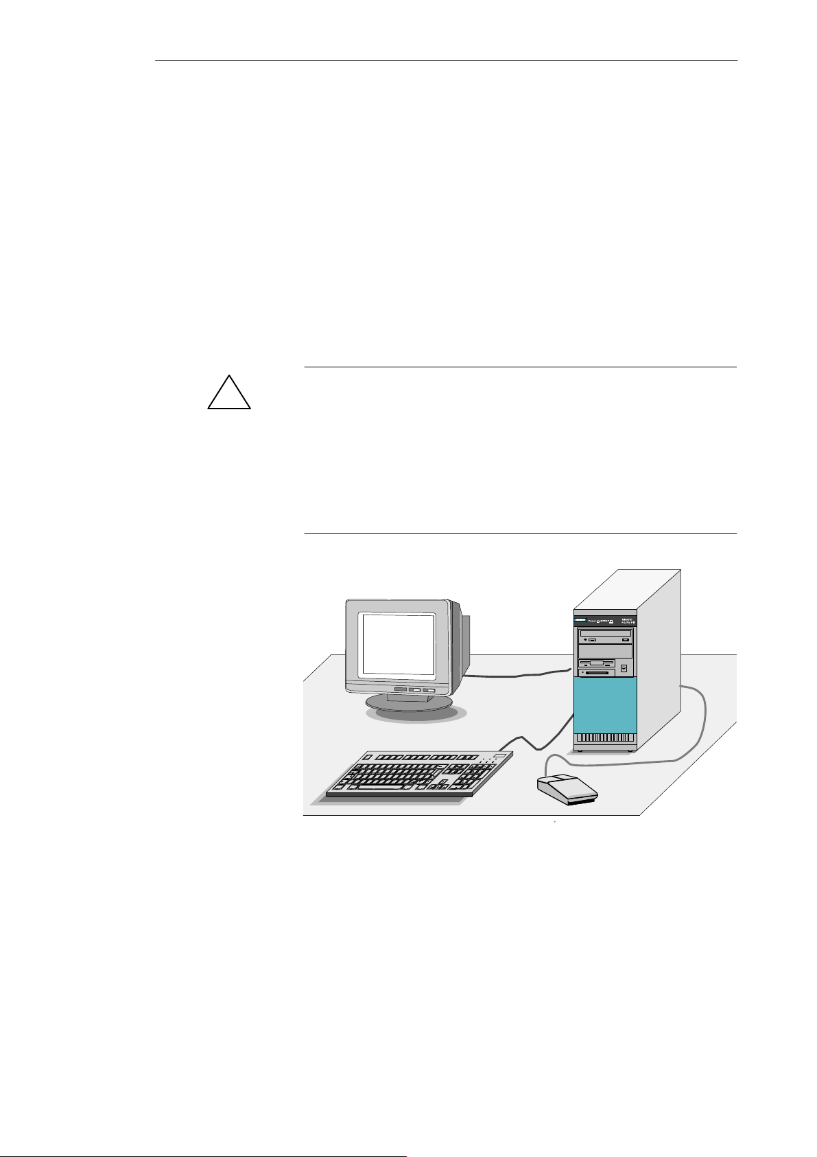
Unpack your PG 760 PII as follows:
1. Remove the packing.
2. Do not throw the original packing away. Keep it in case you have to ship
or transport the unit again at some time in the future.
3. Check the packing list to make sure that no components are missing.
4. Enter the serial number of your PG 760 PII in the table intended for this
purpose on the first page of the Product Information Bulletin. If a device
is reported as stolen, it can only be recognized when submitted for repair
by means of its serial number.
Caution
Risk of damage!
When transporting the unit in cold weather, when it may be submitted to
extreme variations in temperature, make sure that there is no moisture
(condensation) on or in the unit.
The unit must be allowed to reach room temperature before you switch it on.
If condensation has formed, you should wait approximately 12 hours before
switching on the unit.
2-2
Figure 2-1 Setting up a T ower
Proceed as follows:
1. Place the PG 760 PII on a horizontal, flat surface. The ventilation slots on
the front (with the slider open) and on the rear must not be covered.
2. Set up the monitor and keyboard as appropriate. Use the short or long
keyboard cable depending on the situation.
3. Connect the monitor, keyboard and mouse.
PG 760 PII Programming Device
C79000-G7076-C766-01
Unpacking and Setting Up the PG 760 PII
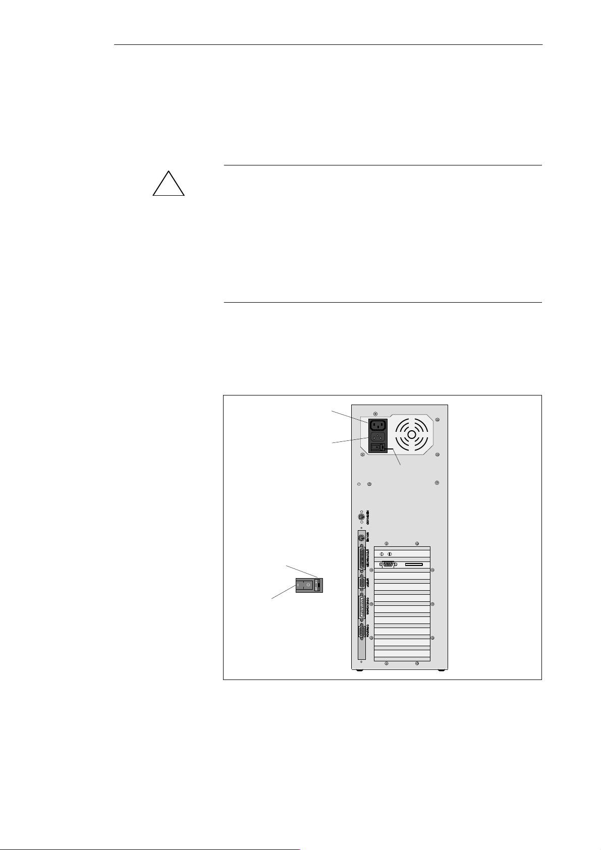
2.2 Components of the PG 760 PII
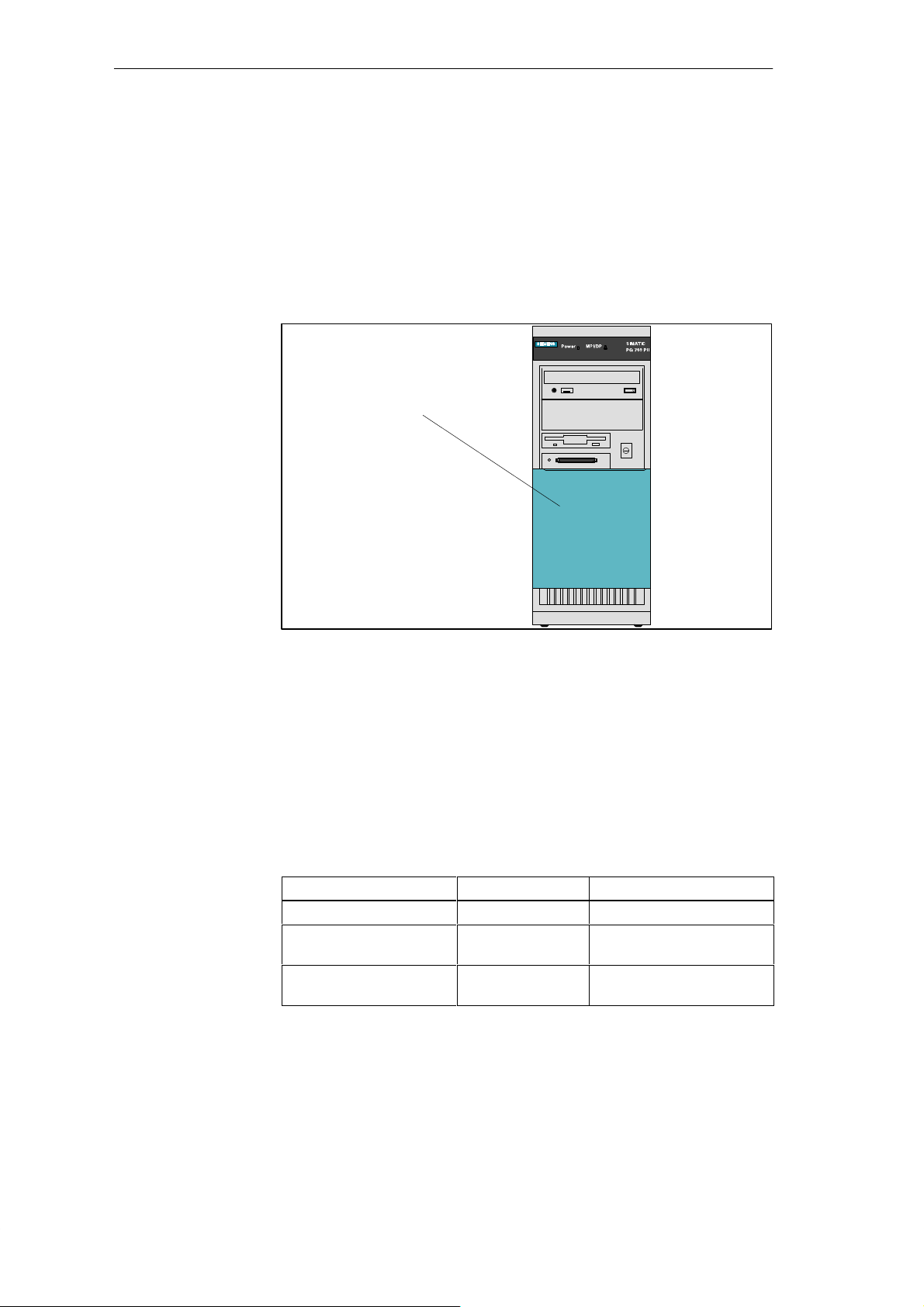
Front Side All the important operator controls are accessible from the front of the
PG 760 PII.
Power supply
connector
socket (out)
Power supply
connector
socket (in)
On/Off Switch
Mains voltage
selector
PS/2 keyboard
PS/2 mouse
LPT 1
Microphone
Loudspeaker
VGA
MPI/DP
COM1
COM2
Ventilator
1
2
3
4
5
6
7
8
Dummy plates covering expansion slots
1 LED displays
2 CD-ROM drive
3 Free slot
4 Diskette drive
5 On/Off switch
Power
MPI/DP
Power LED
MPI/DP port
Hard disk access
Memory card port
active
6 Memory card port
7 Protective cover for disk drive
8 V entilating slots
Figure 2-2 Rear Panel Housing with Connections and Interfaces and Front View of PG 760 PII
PG 760 PII Programming Device
C79000-G7076-C766-01
2-3

Unpacking and Setting Up the PG 760 PII
Rear Panel
(Connections)
Ports and
Connectors
On the rear side of the PG 760 PII are the connectors for the power supply
and interfaces for connection to external devices.
Summary of the ports and connectors on the rear panel of the housing:
Ports and Connectors Function
Appliance plug, inlet
Appliance socket, outlet
PS/2 keyboard Connection for keyboard
PS/2 mouse Connection for PS/2 mouse
LPT1 printer
Parallel interface
MPI/DP multipoint interface Connection for S7 programmable
COM1/V.24/AG
MODEM
Serial interface
COM2/V.24
Mouse
Serial interface
VGA Connection for monitor
Loudspeaker Connection for external stereo
Microphone Connection for microphone (mono)
Connection for power supply
Connection for power supply to monitor
(trackball supported)
Connection for parallel printer
controller and for distributed I/Os
(compatible with CP 5611)
Connection for S5 programmable
controller
Connection for serial mouse
Connection for serial printer
loudspeaker
2-4
PG 760 PII Programming Device
C79000-G7076-C766-01
2.3 Keyboard
Unpacking and Setting Up the PG 760 PII
Keyboard Layout
Esc
~
Caps
Lock
CTRL Alt
F1 F2 F3 F4 F5 F6 F7 F8 F9 F10
! @ ”
1234567 {8 [9 ]0- ß=
# w
QW E R T Y ZUIOP Ü
@
ASDF GHJ KL
>
Y
Z
< |
The keyboard is divided into the following areas:
S Function keys
S Alphanumeric keyboard
S Cursor control keys
S Numeric keypad
1
$ % ^ & & / * ( ( ) ) = __ ? +
XC BN
V
M
m
< ;,> :.?
567
PG 760
Num Scroll
.
.
Page
CORR
Page
. ,
Del
+
Enter
kkk
CTRL
Print
Help
Insert
Delete
F11 F12
}
{
}
*
~
+
[
]
:
Ä
Alt Gr
|
’
”
#
\
Ö
;
Scroll
Home
Pause
BreakSysRq
Page
PageEnd
Num
789
Home
456
123
End
0
Ins
342
Function keys
1
Alphanumeric keyboard
2
Cursor control keys
3
Numeric keypad
4
Figure 2-3 Keyboard
Repeat Function
Setup
Alphanumeric
Keyboard
Numeric keypad active
5
Upper case active
6
Scroll lock active
7
All the keys on the keyboard are of the autorepeat type. The character is
repeated as long as the key is pressed.
The angle of inclination of the keyboard can be raised from 6° to 12° by
using the swivel feet on the back of the keyboard.
The largest block of keys on the keyboard is the alphanumeric keyboard with
all the keys for the letters of the alphabet, numerals and special characters.
The characters are arranged in basically the same way as on a normal
typewriter. However, there are a number of special keys which have special
functions for the PG 760 PII.
PG 760 PII Programming Device
C79000-G7076-C766-01
2-5
Unpacking and Setting Up the PG 760 PII
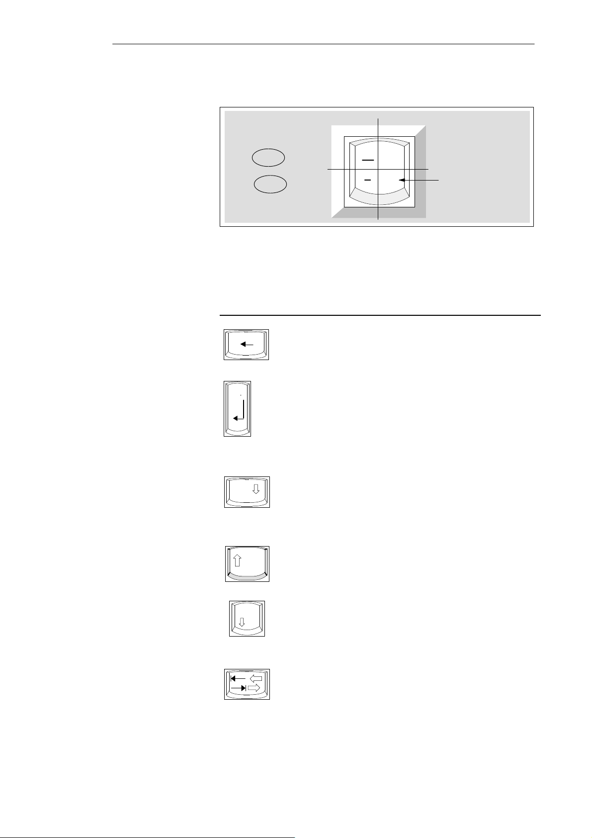
Keyboard Labeling
Special Keys
The keyboard has an international/German labeling system.
International
Shift
Unshift
Figure 2-4 The Keyboard Labeling System
German
?
\
ß
Together with the
ALT Gr key
The special keys in the alphanumeric keyboard have the following functions:
Key Function
Backspace Key
This key moves the cursor one space to the left and deletes the
character at this position.
Caps
Lock
NUM
Enter Key
(Return, Enter, Line Feed)
The return or enter key is used mainly to terminate a command
line in the operating system; that is, the command you have
typed in is executed when you press this key. For other uses of
this key, please refer to the user manual of the relevant
application program.
CAPS LOCK Key
If you press this key, the middle LED at the top right-hand corner
of your keyboard lights up. All upper case characters and other
characters now print normally. If you want to type lower case
letters in this position, you must first press the shift key . If you are
using an international keyboard, press this key again to cancel
the function. The LED then goes out.
If you have a German keyboard, press the shift ⇑ key to cancel
the function.
NUM Key
This key switches the numeric block to cursor control (NUM LED
lights up).
Press this key again to return to cursor control.
T abulator Key
This moves the cursor according to the selected tabulator
positions.
2-6
PG 760 PII Programming Device
C79000-G7076-C766-01

Unpacking and Setting Up the PG 760 PII
Key Function
Ctrl
Alt
Alt Gr
Print
SysRq
Pause
Break
CTRL Key (combination key)
This key is only used in combination with other keys. For
example, you press CTRL + ALT + Del to reset and restart the
operating system. For other uses of this key , please refer to the
user manual of the relevant application program.
ALT Key (combination key)
This key is only used in combination with other keys. For
example, you can enter the hexadecimal value of an ASCII
character using this key and the numeric keypad and thus obtain
additional special characters.
For example, Alt + 123 corresponds to “{”.
AL T Gr Key (combination key)
Y ou can use this key together with the other combination keys to
generate other key codes. For example, you can generate the “\”
character on the German keyboard by typing AL T Gr + ß.
PRINT (combination key)
Using the Print key , you can output the current screen display to
a printer.
P AUSE (combination key)
The Pause key interrupts program execution in the majority of
applications.
Location and
Labeling of the
LEDs
PG 760 PII Programming Device
C79000-G7076-C766-01
There are 3 LED displays on the keyboard, which are located along the
function keys above the numeric keypad.
NUM LOCK
CAPS LOCK
SCROLL LOCK
When the programming device is switched on, the NUM LOCK, CAPS
LOCK and SCROLL LOCK LED displays light up twice briefly. The
keyboard is then ready for operation.
2-7
Unpacking and Setting Up the PG 760 PII
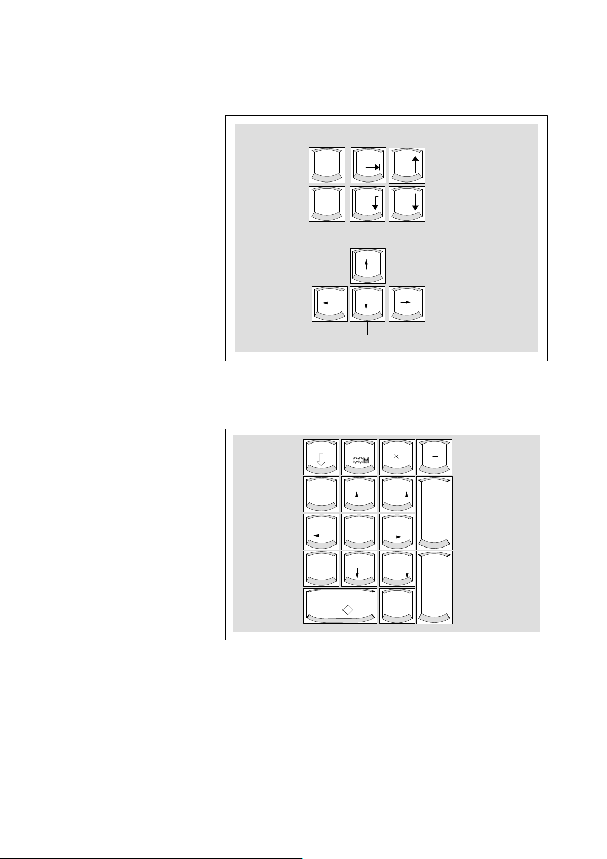
Cursor Keys
The keypad shown below is used for cursor control.
Mover cursor to start of file
Insert
Delete
Move cursor up
Move cursor left
Insert
Delete
Move cursor to end of file
Figure 2-5 Cursor Control Keypad
Home
End
Move cursor down
Page
Page
Page back
Page forward
Move cursor right
Numeric Keypad
Function Keys
The numeric keypad shown below is used to enter numerical data or for
cursor control.
Num
789
456
123
End
0
Ins
Figure 2-6 Numeric Keypad
.
.
CORR
PageHome
Page
. ,
Del
+
Enter
There is a row with twelve function keys located above the alphanumeric
keyboard. The assignment of the individual function keys depends on the
software you are working with.
2-8
PG 760 PII Programming Device
C79000-G7076-C766-01
Unpacking and Setting Up the PG 760 PII
Displays
2.4 Drives
Disk Drive Cover
The displays for the NUM LOCK, CAPS LOCK and SCROLL LOCK keys
are located at the top right of the keyboard, and indicate the current status of
these keys.
The disk drives of your PG 760 PII are protected against dirt penetration by a
sliding cover.
Disk drive coverdown
Drive Types
Floppy Disk Drive
Figure 2-7 Disk Drive Cover
Slide the cover down, so that the disk drives and the power switch are
accessible.
For improved ventilation and protection against dirt, the cover should be
closed during operation.
The PG 760 PII is equipped with the following drives as standard:
T able 2-1 Standard Drives
T ype of Drive Format Capacity
Floppy (diskette) drive 3.5 inch 1.44 Mbytes
Hard disk drive 3.5 inch See Product Information
Bulletin
CD-ROM drive 5.25 inch See Product Information
Bulletin
Using the floppy disk drive you can save programs and data on diskettes or
load them on the PG 760 PII.
PG 760 PII Programming Device
C79000-G7076-C766-01
2-9
Unpacking and Setting Up the PG 760 PII
Types of Diskette
Handling Diskettes
You can use the following diskettes:
Double-Sided High-Density Diskette Double-Sided Double-Density Diskette
3.5 inch 3.5 inch
1.44 Mbytes (135 TPI) 720 Kbytes
80 tracks per side 80 tracks per side
The PG recognizes disks by their coding The PG recognizes disks by their coding
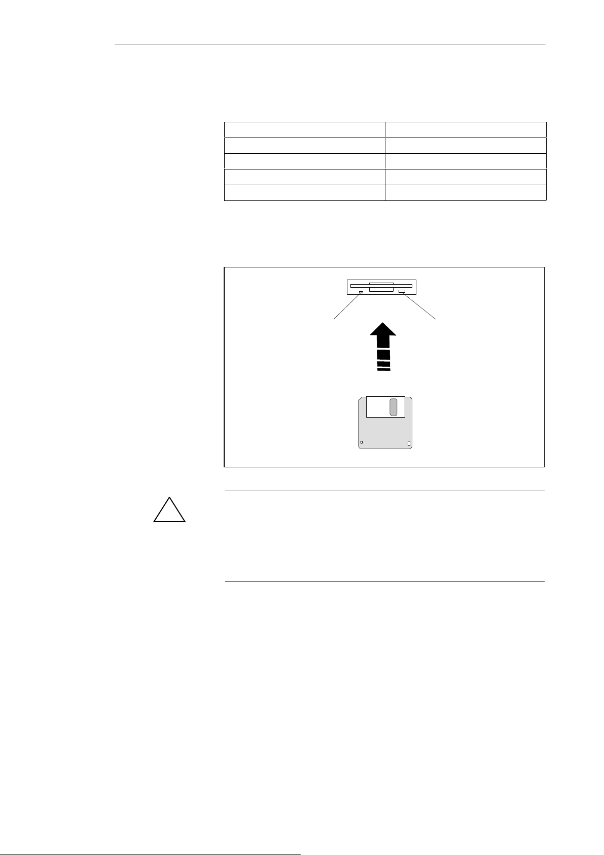
You insert diskettes into the drive as shown below:
Access LED Ejector
2-10
Caution
!
Risk of data loss!
You must not remove the diskette while the access LED is lit, otherwise you
may lose the data on the diskette.
Do not remove the diskette until the access LED on the drive has gone out.
PG 760 PII Programming Device
C79000-G7076-C766-01

Unpacking and Setting Up the PG 760 PII
Hard Disk Drive
!
CD-ROM Drive
You can use a number of different hard disk drives in your PG 760 PII. The
memory capacity of the hard disk can be found in the Product Information
Bulletin and BIOS SETUP program.
The hard disk drive is connected to the first IDE interface (primary IDE). A
second drive can also be connected to this interface as a slave.
Whenever the hard disk drive is accessed, the access LED on the front of the unit
lights up.
Caution
Risk of data loss and damage to drive!
Drives are sensitive to vibration and shock. Any vibration occurring during
operation can lead to loss of data or damage to the drive.
If you intend to move the unit, switch it off and wait until the drive has come
to a stop (after approximately 20 seconds).
The CD-ROM drive permits easy updating of STEP 5 and STEP 7 software
and of WINDOWS 95. The drive is operated via the second IDE interface
(secondary IDE). A second drive can also be operated on this interface. If the
second drive is a hard disk drive, the CD ROM drive should be set as the
slave, and the hard disk drive as the master.
!
Additional
Module Slots
Chapter 7.5 contains a description, and explains handling.
Caution
Risk of data loss and damage to drive!
CD-ROM drives are very sensitive to vibration and shock. Any vibration
occurring during operation can lead to damage to the drive or the data
medium.
The PG 760 PII is equipped with further module slots for the installation of
additional disk drives. For further information, see Chapter 4.5.
PG 760 PII Programming Device
C79000-G7076-C766-01
2-11

Unpacking and Setting Up the PG 760 PII
2.5 Transport
Carrying the
PG 760 PII
!
Despite the robust design of the PG 760 PII, its internal components are
sensitive to severe vibrations or jolts. When moving the PG 760 PII, you
must therefore make sure that it is protected from severe mechanical forces.
Use the original packing material if you have to ship the PG 760 PII from
one location to another.
Caution
Risk of damage!
When transporting the unit cold weather, when it may be submitted to
extreme variations in temprature, make sure that there is no moisture
(condensation) on or in the unit.
The unit must be allowed to reach room temperature slowly before you
switch it on. If condensation has formed, you should wait approximately 12
hours before switching on the unit.
2-12
PG 760 PII Programming Device
C79000-G7076-C766-01

Installing and Operating the PG 760 PII
3
What Does This
Chapter Contain?
Summary of
Sections
This chapter describes what you have to do to set up your PG 760 PII
correctly for operation. This includes:
The basic steps for starting up your PG 760 PII,
Working with memory cards for the programmable controllers, and
Connecting your PG 760 PII to other devices.
In Section You Will Find On Page
3.1 Connecting the PG 760 PII to the Power Supply 3-2
3.2 Connecting I/O Devices 3-4
3.3 W orking with SIMATIC Memory Cards 3-7
3.4 PG 760 PII Connections (Point-to-Point Connections) 3-8
3.5 Multipoint Interface (MPI/DP) 3-12
3.6 SIMATIC NET PROFIBUS 3-14
3.7 SIMA TIC NET Industrial Ethernet 3-15
PG 760 PII Programming Device
C79000-G7076-C766-01
3-1
Installing and Operating the PG 760 PII
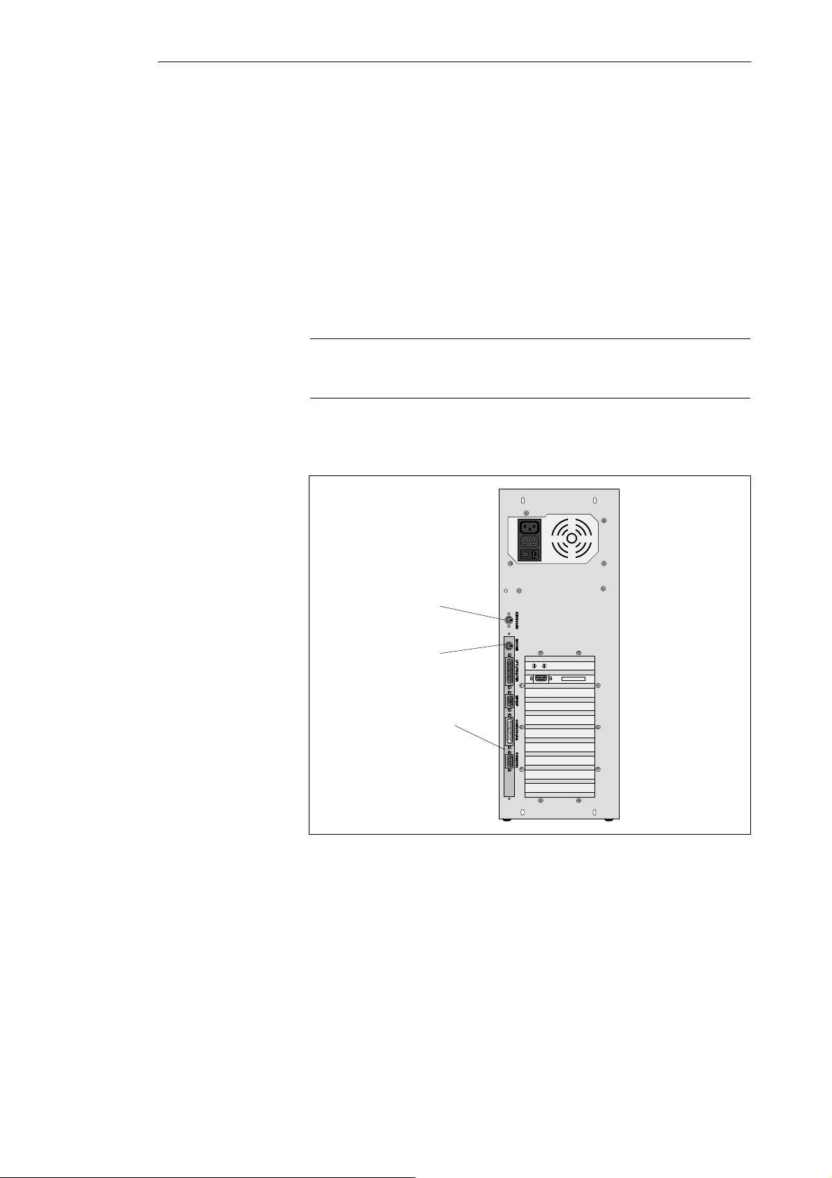
3.1 Connecting the PG 760 PII to the Power Supply
Connecting to the
Power Supply
!
Selecting Mains
Voltage
The PG 760 PII can be operated at 120 V or 240 V. Voltage selection is
carried out via the mains voltage selector.
Caution
Risk of damage to the unit!
Operating the PG 760 PII with the incorrect mains voltage can damage the
unit. When switched on, the same voltage is present on the appliance socket
(outlet) as on the appliance plug (mains inlet). To operate the monitor, please
observe the manufacturer ’s specifications. Only a monitor with the following
rated currents may be connected to the appliance socket:
S 120 V 3 A max.
S 240 V 1.5 A max.
If the voltage displayed on the system selector switch does not correspond
with your local voltage, you must move the mains voltage selector so that the
voltage set next to the white triangle is visible.
To do this, use a small, flat screwdriver to lever out the part with the voltages
printed on it and replace it in the appropriate position.
Appliance socket
(outlet)
Appliance socket
(inlet)
Mains voltage
selector
On/Off switch
Figure 3-1 Mains Voltage Selector
B
Mains
voltage
selector
3-2
PG 760 PII Programming Device
C79000-G7076-C766-01

Installing and Operating the PG 760 PII
Connecting the
Power Cable
Proceed as follows:
1. Check that the correct voltage has been selected.
2. Plug the supplied power cable into the power supply connector.
3. Connect the unit to a socket outlet with a grounded protective conductor.
Note
The power plug must be disconnected to isolate the unit completely from the
supply.
For operation in Canada and the USA, a CSA or UL-listed power supply
cable must be used.
For the United States and Canada:
In the United States and Canada the cord must be UL Listed and CSA
Labelled. The male plug is a NEMA 5-15 style.
For operation with 120 V:
Use a UL Listed, CSA Labelled Cord Set, consisting of a min. 18 AWG.
Type SVT or SJT three conductor flexible cord, max. 4.5 m (15 feet) in
length and a parallel blade grounding type attachment plug, rated 15 A,
min 125 V.
For operation with 240 V (within the USA):
Use a UL Listed, CSA Labelled Cord Set, consisting of a min. 18 AWG.
Type SVT or SJT three conductor flexible cord, max. 4.5 m (15 feet) in
length and a tandem blade grounding type attachment plug, rated 15 A,
250 V.
For operation with 230 V (outside of USA):
Use a Cord Set consisting of a min 18 AWG cord and grounding type
attachment plug rated 15A, 250 V. The cord set should have the approviate
safety approvals for the country in which the equipment will be installed and
marked.
The unit is intended for operation with grounded power supply networks
(TN networks, VDE 0100 part 300 or IEC 364-3).
The unit is not intended for operation with non-grounded or
impedance-grounded systems (IT networks).
The mains cable should fulfill the safety requirements of the country in
which you are operating the device.
PG 760 PII Programming Device
C79000-G7076-C766-01
3-3
Installing and Operating the PG 760 PII
3.2 Connecting I/O Devices
Connecting a PS/2
Keyboard
Using a Mouse
Connecting a PS/2
Mouse
Connect the keyboard as follows:
1. Switch off your PG 760 PII.
2. Plug in the PS/2 keyboard connector.
You can connect both a PS/2 and a serial mouse to the PG 760 PII. When the
PG 760 PII is supplied, the mouse driver for the PS/2 mouse is already
loaded.
Note
A PS/2 mouse and a serial mouse cannot be operated at the same time.
Connect a PS/2 mouse or another pointing device to the mouse connector.
Port for
PS/2 keyboard
Port for
PS/2 mouse
COM2 port for
serial mouse
Figure 3-2 Connections for Keyboard, PS/2 Mouse and Serial Mouse
Connect the mouse as follows:
1. Switch off your PG 760 PII.
2. Plug the cable of the PS/2 mouse or another pointing device into the
mouse connector.
3. Switch on your PG 760 PII again.
3-4
PG 760 PII Programming Device
C79000-G7076-C766-01
Installing and Operating the PG 760 PII
Connecting a
Serial Mouse
Recommended
Monitors
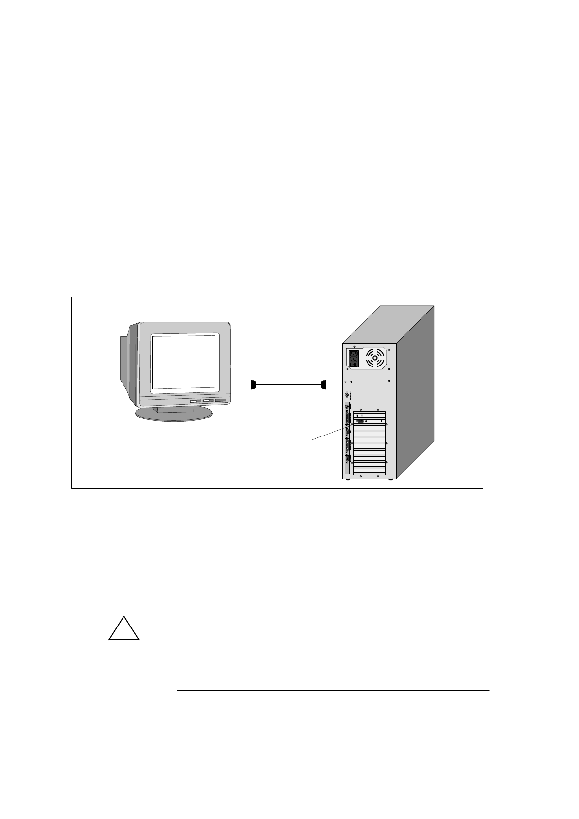
Connecting
Monitors
You can connect a serial mouse to the COM2 serial port. To operate a serial
mouse, the appropriate mouse driver must be initialized and assigned
parameters. You will find the information you need to do this in the
description of your mouse or in the description of the operating system.
Proceed as follows:
1. Switch off your PG 760 PII.
2. Plug the serial mouse into the connector labeled COM2.
3. Switch on your PG 760 PII again.
You can connect external multisynchronous monitors using the standard
VGA connector on the rear panel of the unit. We recommend that you use
Siemens monitors.
You must switch off the PG 760 PII before connecting the monitor cable. You
will find further information about the connector pinout in Chapter 7.
Figure 3-3 Connection to Monitor
Connect the monitor as follows:
1. Switch off the PG 760 PII and the monitor.
2. Plug the monitor cable into the VGA socket.
3. Plug the other end of the monitor cable into the monitor.
For technical specifications on the graphics interface, please refer to the
Product Information Bulletin.
Caution
!
Danger of damaging the monitor!
If you want to set higher frequencies and resolutions, first make sure that the
monitor you are using is suitable for a higher frequency and resolution.
If the frequency is too high, this may damage the monitor.
PG 760 PII Programming Device
C79000-G7076-C766-01
VGA socket for monitor
3-5
Installing and Operating the PG 760 PII
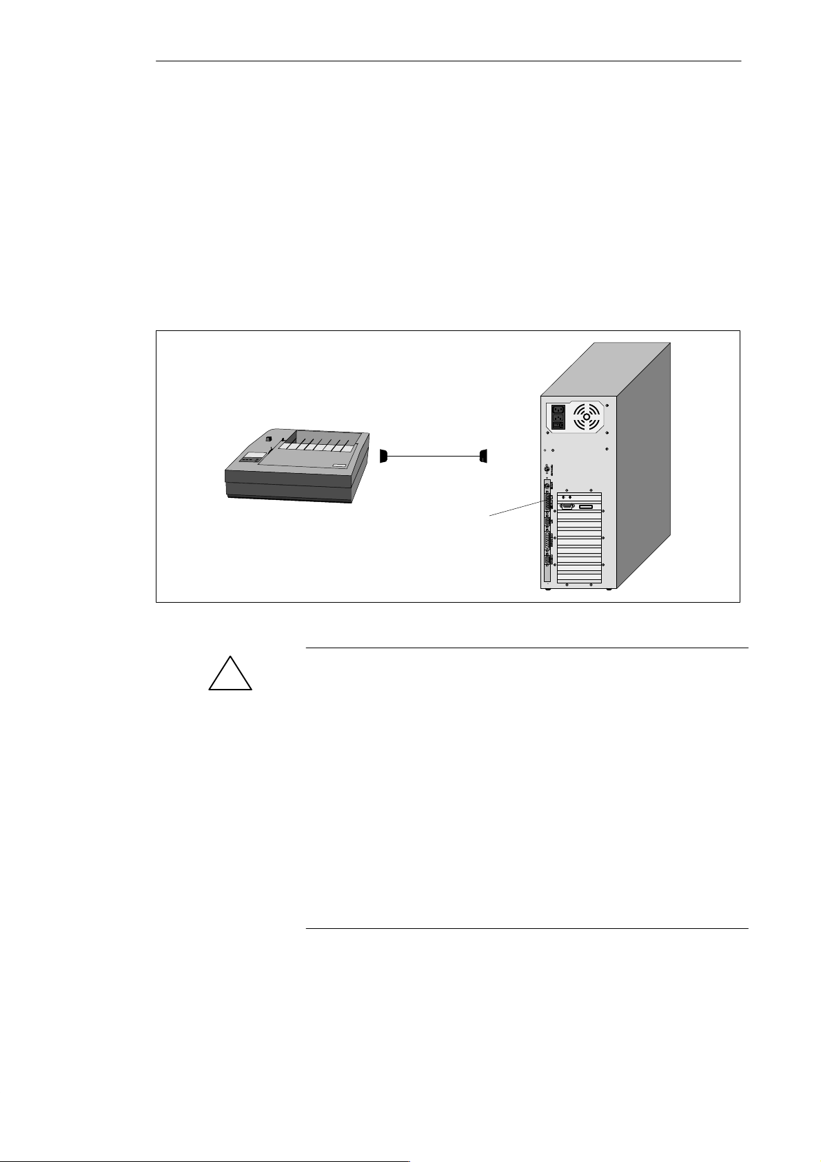
Recommended
Printers
Connecting the
Printer to the
Parallel Port
Siemens printers with a parallel interface and IBM character set are
recommended for use with the PG 760 PII programming device.
To connect your printer, proceed as follows:
1. Switch off the PG 760 PII and printer.
2. Plug the printer cable into the LPT1 parallel port.
3. Plug the printer cable into the parallel port of the printer.
4. Screw the connector tight at the interface port.
LPT1 (parallel)
Figure 3-4 Location of Printer Interface Ports
!
Caution
Risk of damage to the unit!
Switch off the unit before connecting the parallel printer to the LPT 1 port
(the printer should also be switched off).
Make sure that you use the right port, otherwise you may damage the printer
or the programming device.
The interface port may be damaged if you confuse the connections or use the
wrong connecting cables.
Before plugging in the cables, the electrostatic charge of your body, the unit
and the cables must be equalized. To do this, briefly touch an earthed object
(ESD Guidelines).
Only use the original connecting cables.
3-6
PG 760 PII Programming Device
C79000-G7076-C766-01
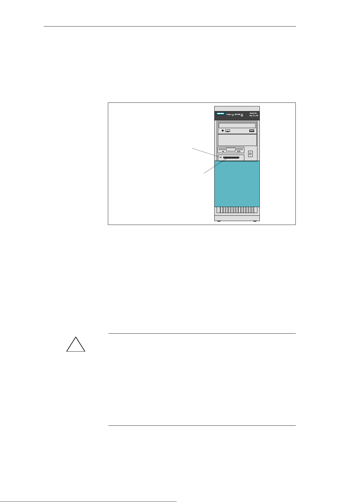
3.3 Working with SIMATIC Memory Cards
Installing and Operating the PG 760 PII
Working with
SIMATIC Memory
Cards
SIMATIC memory cards can be read, programmed and erased using the
68-pin connector.
Orientation point
SIMA TIC Memory Cards
Figure 3-5 SIMATIC Memory Card Port
Proceed as follows when working with SIMATIC memory cards:
1. Switch on your PG 760 PII.
2. Start your SIMATIC programming function.
3. Plug the SIMATIC memory card into the 68-pin connector.
4. Read, program or erase the memory card with the programming function
of your SIMATIC software.
5. Terminate the programming function of your SIMATIC software.
6. Remove the SIMATIC memory card from the programming port for
further use in a programmable logic controller.
Caution
!
Risk of damage to memory cards and the PG 760 PII!
You must insert the memory card into the 68-pin connector with the type
label pointing to the power switch. Make sure that the orientation points on
are matching those of the card.
You must not remove the SIMATIC memory card while the LED display for
the programming EPROM is lit.
You must set the Programming Interface to Enabled in the BIOS SETUP
program in the submenu Hardware Options before you can program the
SIMATIC memory card.
PG 760 PII Programming Device
C79000-G7076-C766-01
3-7

Installing and Operating the PG 760 PII
3.4 PG 760 PII Connections (Point-to-Point Connections)
Point-to-Point
Connection
Suggestions for
Configuring TTY
(20 mA) Interfaces
Rules
In this section, you will learn how to connect your PG 760 PII to a
programming device or programmable controller using a point-to-point
connection.
You can establish a point-to-point connection by connecting the PG 760 PII
to another programming device or a programmable controller via:
A V.24 connection.
A TTY connection.
Reliable data transfer depends on several factors. The data transfer rate you
can achieve depends on the distance, the type of cable, the type of interface
and any interference present.
You can reduce interference by choosing the right transmission cable and
connecting it properly, and observing the following guidelines:
Use a shielded cable with a low surge impedance (< 130 W / km) and low
capacitance (< 90 pF/m). Twisted-pair cables enhance noise immunity
due to inductance. A low surge impedance results in reduced voltage
excursions and shorter charge reversal times. The larger the conductor
cross-section, the lower the surge impedance for the same length of cable.
The shorter the transmission link, the higher the maximum possible data
transfer rate.
If there is an active sender and an active receiver at the same end of the
transmission link, the sequence of access priority to the transmission
circuit must be taken into account in order to achieve the longest possible
transmission link.
Signal lines and power lines must not be run together. Signal lines must
be installed as far away as possible from strong interference sources
(for example, 400 V three-phase power cables).
The active TTY interface with 12 V no-load voltage has been tested on a
1000 m (3300 ft.) long cable at a transmission rate of 9600 bps in a
normal noisy environment (field strength < 3 V/m or 1 V/ft.). If a
shielded LiYCY 5x1x0.14 is used, reliable transmission is possible over a
distance of up to 1000 m (3300 ft.). The AS511 protocol (only one
transmitter at a time) was used for testing.
Note
The contaminating field of the interference source decreases exponentially
with the distance.
3-8
PG 760 PII Programming Device
C79000-G7076-C766-01
 Loading...