

Siemens Simatic PG 740 User Manual
Preface, Contents
SIMATIC
Programming Device PG 740
Manual
Product Overview
Installing the PG 740
Starting Up the PG 740
PG 740 Expansions
Configuring the PG 740
Error Diagnostics
Hardware Information
Glossary, Index
1
2
3
4
5
6
7
C79000-G7076-C742-01
Safety Guidelines
!
!
!
This manual contains notices which you should observe to ensure your own personal safety, as well as to
protect the product and connected equipment. These notices are highlighted in the manual by a warning
triangle and are marked as follows according to the level of danger:
Danger
means that death, severe personal injury or substantial property damage will result if proper precautions are
not taken.
Warning
indicates that death, severe personal injury or substantial property damage can result if proper precautions are
not taken.
Caution
indicates that minor personal injury or property damage can result if proper precautions are not taken.
Note
draws your attention to particularly important information on the product, handling the product, or to a particular
part of the documentation.
Qualified Personnel
Correct Usage
The device/system may only be set up and operated in conjunction with this manual.
Only qualified personnel should be allowed to install and work on this equipment. Qualified persons in the
sense of the safety guidelines of this Manual are defined as persons who are authorized to commission, to
ground and to tag equipment, systems and circuits in accordance with established safety practices and standards.
Note the following:
Warning
!
Trademarks
The reproduction, transmission or use of this document or its contents is
not permitted without express written authority. Of fenders will be liable for
damages. All rights, including rights created by patent grant or registration
of a utility model or design, are reserved.
Siemens AG
Automation Group
Industrial Automation Systems
Postfach 4848, D-90327 Nürnberg
This device and its components may only be used for the applications described in the catalog or the technical
description, and only in connection with devices or components from other manufacturers which have been
approved or recommended by Siemens.
This product can only function correctly and safely if it is transported, stored, set up, and installed correctly, and
operated and maintained as recommended.
SIMATICR and SINECR are registered trademarks of SIEMENS AG.
Third parties using for their own purposes any other names in this document which refer to
trademarks might infringe upon the rights of the trademark owners.
Disclaimer of LiabilityCopyright E Siemens AG 1996 All rights reserved
We have checked the contents of this manual for agreement with the
hardware and software described. Since deviations cannot be precluded
entirely, we cannot guarantee full agreement. However, the data in this
manual are reviewed regularly and any necessary corrections included in
subsequent editions. Suggestions for improvement are welcomed.
E Siemens AG 1996
T echnical data subject to change.
Siemens Aktiengesellschaft
Order No. 6ES7740-2AA00-8BA0
Programming Device PG 740

Preface
What this Manual
is About
Who is the Manual
Intended For?
Other Manuals
This manual contains all the information you need for working with the
PG 740 programming device. You can use it to
S unpack the programming device and power it up.
S familiarize yourself with the functions and settings of the various
components (display, keyboard, programming facilities etc.).
S connect the programming device up to other units of equipment
(programmable controllers, other programming devices).
S expand your system, provided you comply with the necessary conditions.
S analyze and eliminate simple faults.
The following persons require the manual:
S Users commissioning the programming device themselves or working
with it (editing, programming or debugging).
S System administrators operating the programming device in a network.
S Service and maintenance personnel using the PG 740 for system
expansion purposes or error/fault analysis.
This manual does not contain information on the operating system or
programming software. You will find this information in the relevant
software manuals.
Product
Information
Bulletin
Product
Information
Programming Device PG 740
C79000-G7076-C742-01
The Product Information Bulletin supplied with the PG 740 contains the
latest technical specifications of the programming device, and the addresses
and telephone numbers of the repair and maintenance centers and the hotline.
When your PG 740 is delivered, you also receive a Product Information
leaflet with information on the latest software release.
iii

Preface
Queries
Pointers through
the Manual
Installation
Startup
If you have any questions concerning subjects not covered in the manual, just
get in touch with the Siemens representative in your area.
If you have any questions on the manual itself or would like to make remarks
or suggestions, please complete the reply card at the end of the manual. We
would also appreciate it if you would include your own personal opinion on,
and appraisal of, the manual on the reply card.
The manual contains both the most important instructions for starting up and
using the programming device, as well as reference sections you will only
require in special cases.
Before you use the PG 740 for the first time, read Chapter 2 on the PG 740’s
components and functionality.
Chapter 3 describes the basic steps necessary for starting up the PG 740. This
section also contains instructions for working with memory cards for
programmable controllers and for connecting the programming device to
other devices.
Expansion
Configuration
Error/Fault
Diagnostics
Reference Data
Glossary
Alphabetical Index
Chapter 4 describes how to expand your PG 740 (installation of memory
expansion or additional modules). Please observe the safety notes.
Modifications to the system hardware may make it necessary for you to adapt
the original hardware configuration. Chapter 5 tells how to proceed in this
case.
Chapter 6 will tell you how to deal with simple faults that you can diagnose
and, in some cases, eliminate yourself.
Chapter 7 contains hardware addresses, interrupt assignments and
information on connecting cables.
The glossary explains important terms.
The index will enable you to quickly find passages in the text pertaining to
important keywords.
Programming Device PG 740
iv
C79000-G7076-C742-01

Contents
1 Product Overview 1-1. . . . . . . . . . . . . . . . . . . . . . . . . . . . . . . . . . . . . . . . . . . . . . . . . . . . . . .
2 Installing the PG 740 2-1. . . . . . . . . . . . . . . . . . . . . . . . . . . . . . . . . . . . . . . . . . . . . . . . . . . . .
2.1 Setting up the PG 740 2-2. . . . . . . . . . . . . . . . . . . . . . . . . . . . . . . . . . . . . . . . . . . .
2.2 Hardware Components of the PG 740 2-6. . . . . . . . . . . . . . . . . . . . . . . . . . . . . .
2.3 Display 2-9. . . . . . . . . . . . . . . . . . . . . . . . . . . . . . . . . . . . . . . . . . . . . . . . . . . . . . . . .
2.4 Keyboard 2-10. . . . . . . . . . . . . . . . . . . . . . . . . . . . . . . . . . . . . . . . . . . . . . . . . . . . . . .
2.5 Trackball 2-16. . . . . . . . . . . . . . . . . . . . . . . . . . . . . . . . . . . . . . . . . . . . . . . . . . . . . . . .
2.6 Drives 2-18. . . . . . . . . . . . . . . . . . . . . . . . . . . . . . . . . . . . . . . . . . . . . . . . . . . . . . . . . .
2.7 Transport 2-20. . . . . . . . . . . . . . . . . . . . . . . . . . . . . . . . . . . . . . . . . . . . . . . . . . . . . . .
3 Starting Up the PG 740 3-1. . . . . . . . . . . . . . . . . . . . . . . . . . . . . . . . . . . . . . . . . . . . . . . . . . .
3.1 Connecting the PG 740 to the Power Supply 3-2. . . . . . . . . . . . . . . . . . . . . . . .
3.2 Connecting I/O Devices 3-3. . . . . . . . . . . . . . . . . . . . . . . . . . . . . . . . . . . . . . . . . . .
3.3 Working with SIMATIC S5 Memory Submodules 3-9. . . . . . . . . . . . . . . . . . . . .
3.4 Working with SIMATIC Memory Cards 3-10. . . . . . . . . . . . . . . . . . . . . . . . . . . . . .
3.5 Working with PCMCIA Cards 3-11. . . . . . . . . . . . . . . . . . . . . . . . . . . . . . . . . . . . . .
3.6 PG 740 Connections (Point-To-Point Connections) 3-12. . . . . . . . . . . . . . . . . . .
3.7 Multipoint Interface (MPI/DP) 3-16. . . . . . . . . . . . . . . . . . . . . . . . . . . . . . . . . . . . . .
3.8 SINEC L2 3-18. . . . . . . . . . . . . . . . . . . . . . . . . . . . . . . . . . . . . . . . . . . . . . . . . . . . . . .
3.9 SINEC H1 3-19. . . . . . . . . . . . . . . . . . . . . . . . . . . . . . . . . . . . . . . . . . . . . . . . . . . . . . .
4 PG 740 Expansions 4-1. . . . . . . . . . . . . . . . . . . . . . . . . . . . . . . . . . . . . . . . . . . . . . . . . . . . . .
4.1 Opening the Unit 4-2. . . . . . . . . . . . . . . . . . . . . . . . . . . . . . . . . . . . . . . . . . . . . . . . .
4.2 Functional Units Visible after Opening the Unit 4-4. . . . . . . . . . . . . . . . . . . . . . .
4.3 Installing Expansion Modules 4-10. . . . . . . . . . . . . . . . . . . . . . . . . . . . . . . . . . . . . .
4.4 Installing Memory Expansion Cards 4-12. . . . . . . . . . . . . . . . . . . . . . . . . . . . . . . .
4.5 Installing a Cache 4-15. . . . . . . . . . . . . . . . . . . . . . . . . . . . . . . . . . . . . . . . . . . . . . . .
4.6 Back-Up Battery 4-16. . . . . . . . . . . . . . . . . . . . . . . . . . . . . . . . . . . . . . . . . . . . . . . . .
4.7 Processor Upgrade 4-17. . . . . . . . . . . . . . . . . . . . . . . . . . . . . . . . . . . . . . . . . . . . . . .
4.8 Closing the Unit 4-17. . . . . . . . . . . . . . . . . . . . . . . . . . . . . . . . . . . . . . . . . . . . . . . . . .
5 Configuring the PG 740 5-1. . . . . . . . . . . . . . . . . . . . . . . . . . . . . . . . . . . . . . . . . . . . . . . . . .
5.1 Changing the System Configuration with SETUP 5-2. . . . . . . . . . . . . . . . . . . . .
Programming Device PG 740
C79000-G7076-C742-01
v

Contents
5.1.1 The Main Menu 5-5. . . . . . . . . . . . . . . . . . . . . . . . . . . . . . . . . . . . . . . . . . . . . . . . . .
5.1.2 The Advanced Menu 5-15. . . . . . . . . . . . . . . . . . . . . . . . . . . . . . . . . . . . . . . . . . . . .
5.1.3 The Security Menu 5-17. . . . . . . . . . . . . . . . . . . . . . . . . . . . . . . . . . . . . . . . . . . . . . .
5.1.4 The Power Menu 5-18. . . . . . . . . . . . . . . . . . . . . . . . . . . . . . . . . . . . . . . . . . . . . . . . .
5.1.5 The Exit Menu 5-20. . . . . . . . . . . . . . . . . . . . . . . . . . . . . . . . . . . . . . . . . . . . . . . . . . .
5.2 PCI Configuration 5-22. . . . . . . . . . . . . . . . . . . . . . . . . . . . . . . . . . . . . . . . . . . . . . . .
5.3 Configuring the PCMCIA Interface 5-22. . . . . . . . . . . . . . . . . . . . . . . . . . . . . . . . . .
6 Error Diagnostics 6-1. . . . . . . . . . . . . . . . . . . . . . . . . . . . . . . . . . . . . . . . . . . . . . . . . . . . . . . .
7 Hardware Information 7-1. . . . . . . . . . . . . . . . . . . . . . . . . . . . . . . . . . . . . . . . . . . . . . . . . . . .
7.1 Hardware Address Table 7-2. . . . . . . . . . . . . . . . . . . . . . . . . . . . . . . . . . . . . . . . . .
7.2 Interrupt Assignments 7-7. . . . . . . . . . . . . . . . . . . . . . . . . . . . . . . . . . . . . . . . . . . .
7.3 PG 740 Video Modes 7-8. . . . . . . . . . . . . . . . . . . . . . . . . . . . . . . . . . . . . . . . . . . . .
7.4 Connector Pinouts 7-9. . . . . . . . . . . . . . . . . . . . . . . . . . . . . . . . . . . . . . . . . . . . . . .
7.5 Connecting Cables 7-16. . . . . . . . . . . . . . . . . . . . . . . . . . . . . . . . . . . . . . . . . . . . . . .
Glossary Glossary-1. . . . . . . . . . . . . . . . . . . . . . . . . . . . . . . . . . . . . . . . . . . . . . . . . . . . . . . . . .
Index Index-1. . . . . . . . . . . . . . . . . . . . . . . . . . . . . . . . . . . . . . . . . . . . . . . . . . . . . . . . . . . . .
Programming Device PG 740
vi
C79000-G7076-C742-01
Product Overview
1
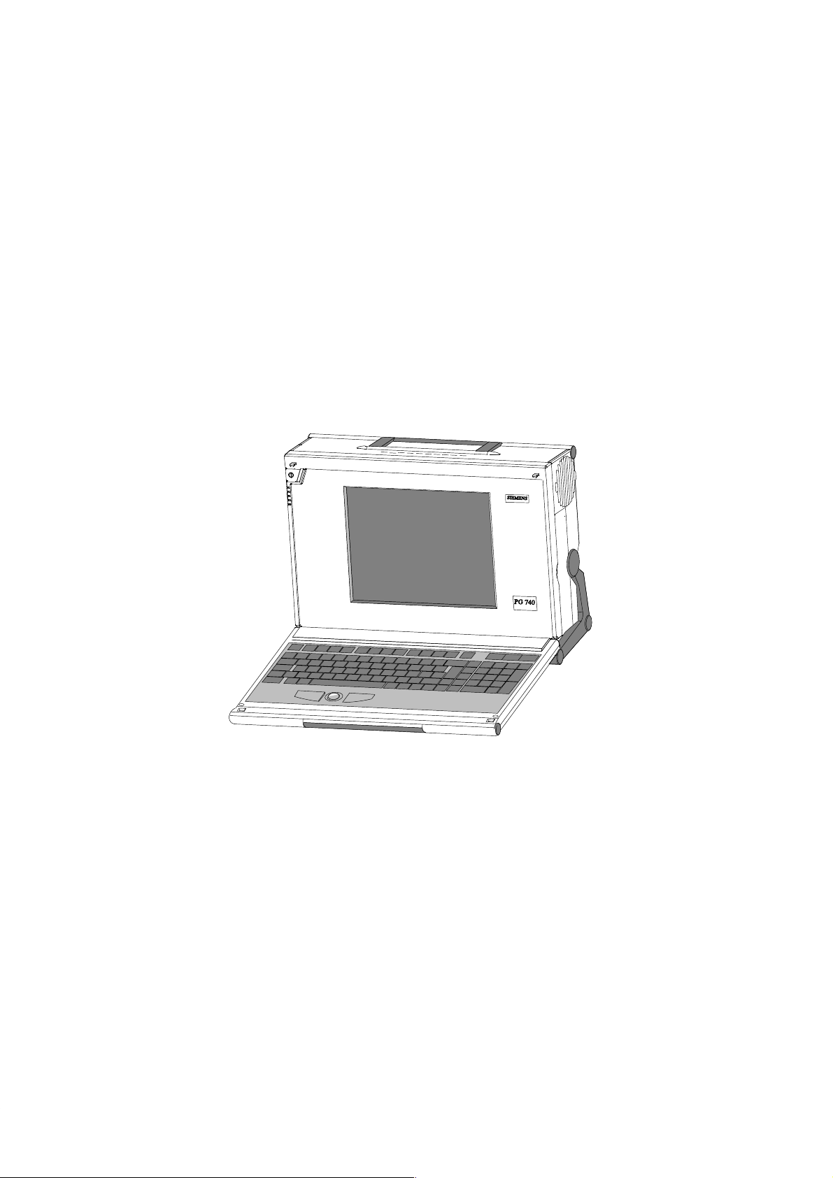
Application
The PG 740 programming device is a high-performance device, equipped
with the optimum hardware features and software for programming,
debugging, and starting up programmable controllers in an automation
environment.
Hardware/Software
Complement
Programming Device PG 740
C79000-G7076-C742-01
You can use the PG 740 programming device to program SIMATIC S5 and
SIMATIC S7 programmable controllers. It has
S interface ports for connection to the programmable controllers
S programming facilities for S5 and S7 memory cards.
The PG 740 is shipped with the software listed in the Product Information
leaflet.
1-1

Product Overview
1
Advantages of
the PG 740
Compared to a PC with standard hardware and software, the PG 740
programming device of the SIMATIC family has numerous advantages:
You can develop, debug and document user programs for SIMATIC S5
and SIMATIC S7 programmable logic controllers with the PG 740
without the need for additional hardware or software.
The rugged design and functionality of the PG 740 make it particularly
suitable for use on site under hostile industrial conditions. The PG 740
meets the specific requirements of industrial environments, such as
noise immunity, compliance with the relevant standards, ruggedness,
simple transportation and startup.
The PG 740 can be set up and operated in a large number of different
ways and positions, and can therefore be used practically everywhere it
is needed.
The PG 740 has all the integral ports necessary for connecting it to
SIMATIC automation devices:
– Programming interface for SIMATIC S5 EPROMs and EEPROMs
– Programming interface for SIMATIC S5 and SIMATIC S7 memory
cards in credit-card format
– Interfaces for connection to S5 and S7 programmable controllers.
The PG 740 is supplied with all the necessary system and automation
software already installed on the hard disk.
Since MS-DOS and Windows are also already installed, you can, of
course, also use the PG 740 as a stand-alone workstation, and run all
the standard software available on the market that requires MS-DOS or
Windows.
The PG 740 has the power and expansion capability of normal PCs,
and can therefore also be used as a fully-fledged personal computer.
1-2
Programming Device PG 740
C79000-G7076-C742-01
Installing the PG 740
2
What Does this
Chapter Contain?
Summary of
Sections
What Will You
Know at the End of
this Chapter?
This chapter describes how you install your PG 740. It provides you with
comprehensive information on the major components of the PG 740, such as:
S drives
S keyboard, and
S programming facilities.
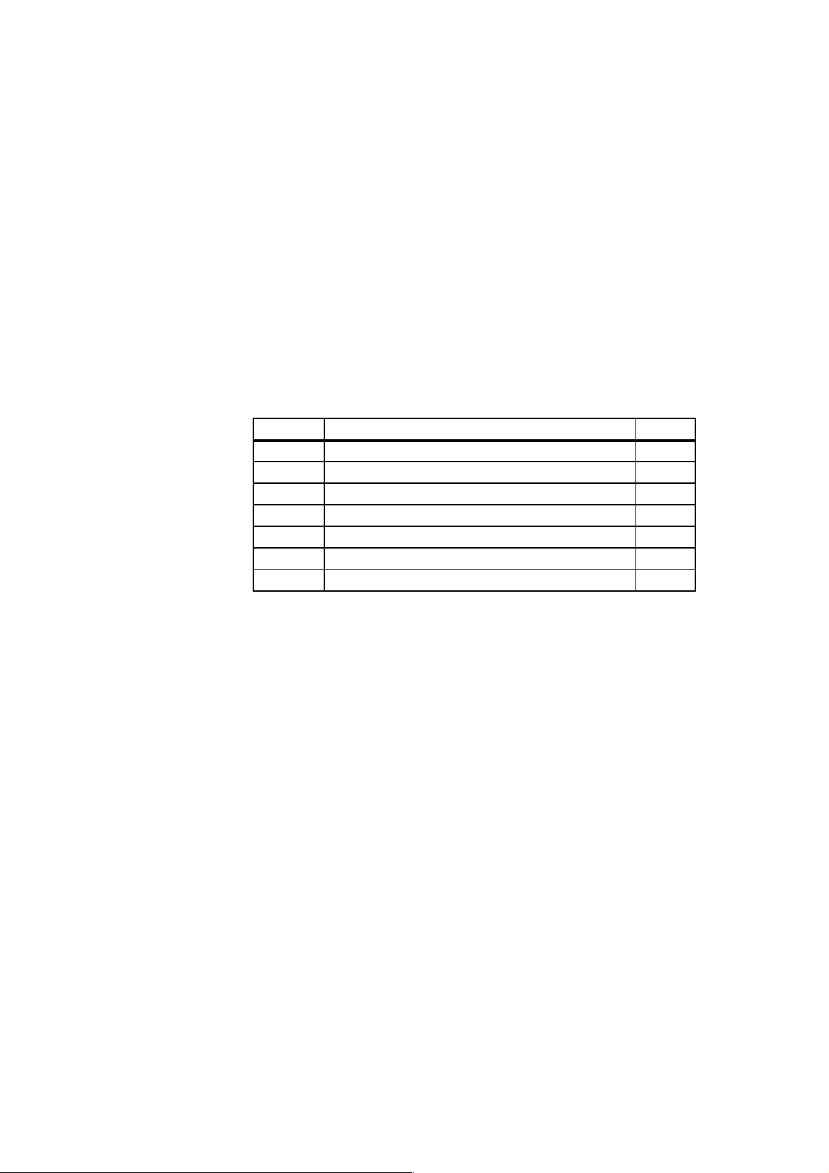
In Section You Will Find On Page
2.1 Setting up the PG 740 2-2
2.2 Hardware Components of the PG 740 2-6
2.3 Display 2-9
2.4 Keyboard 2-10
2.5 Trackball 2-16
2.6 Drives 2-18
2.7 Transport 2-20
When you have worked through this chapter, you will be familiar with
S the procedures to follow when unpacking your PG 740
S the major components of the PG 740 and their functions, and
Programming Device PG 740
C79000-G7076-C742-01
S the right way to transport the unit.
2-1
Installing the PG 740
2.1 Setting up the PG 740
2
Unpacking the
PG 740
!
Desk-Top
Mounting
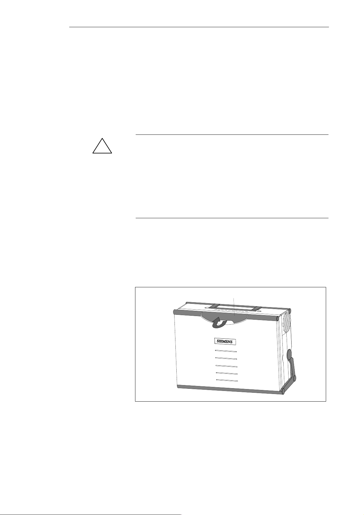
Unpack your PG 740 as follows:
1. Remove the packing.
2. Do not throw the original packing away. Keep it in case you have to
transport the unit again sometime in the future.
3. Check with the packing list to make sure no components are missing.
Caution
Risk of damage!
When transporting the unit in cold weather, when it may be submitted to
extreme variations in temperature, make sure that no condensation is
allowed to form on or in the unit.
The unit should be allowed to reach room temperature slowly before it is
started up. If condensation has formed, the unit should be left for
approximately 12 hours (with a temperature difference of -20° C to + 20° C
(-4° F to + 68° F)) before being switched on.
The PG 740 is usually mounted on a desk or table top. T o make working with
the PG 740 easier, it can be adapted as follows to the particular workplace:
1. Set the PG 740 down on the desk or table top.
2. Open the keyboard lock by pulling up the anthracite-colored handle.
3. Swing the keyboard down into position.
Handle
Figure 2-1 Handle for Unlocking Keyboard
2-2
Programming Device PG 740
C79000-G7076-C742-01
Installing the PG 740
Changing the
Angle of
Inclination
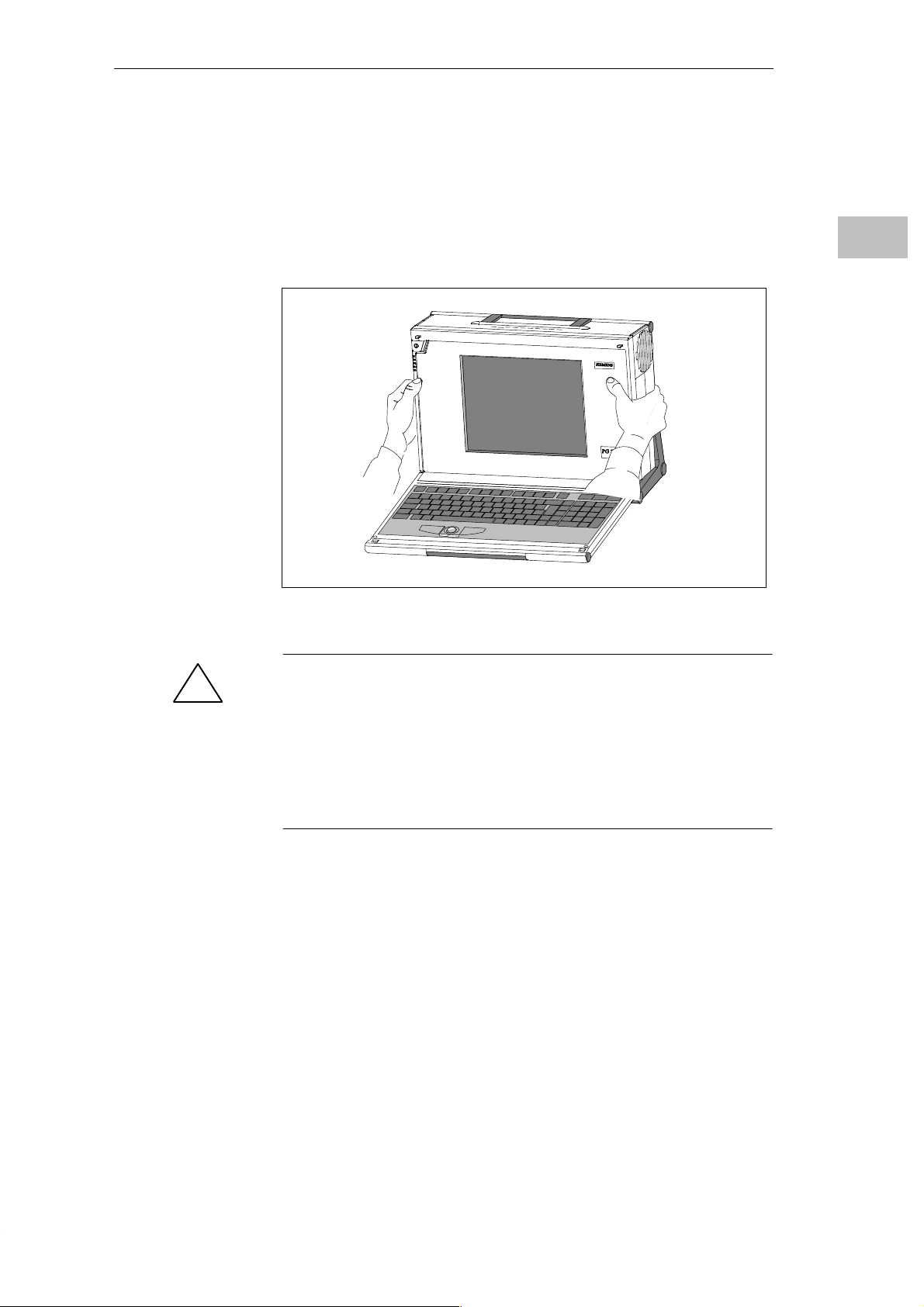
With the keyboard open, you can incline the unit to any angle between 0 and
90° around the axis of rotation of its stand. Proceed as follows:
1. Swing the keyboard down.
2. Pull the extra support (Figure 2-3) out of the rear of the stand.
3. Incline the unit to the angle you prefer.
2
Figure 2-2 Changing the Angle of Inclination
Caution
!
Risk of injury!
There is a danger of the unit tipping over if it is set up without extra support
and at an angle of inclination of more than 15°. This could lead to personal
injury and also damage to the unit.
If the angle of inclination is greater than 15°, you must use the extra
slide-out support in the stand.
Programming Device PG 740
C79000-G7076-C742-01
2-3
Installing the PG 740
2
Horizontal
Mounting
Detaching the
Keyboard
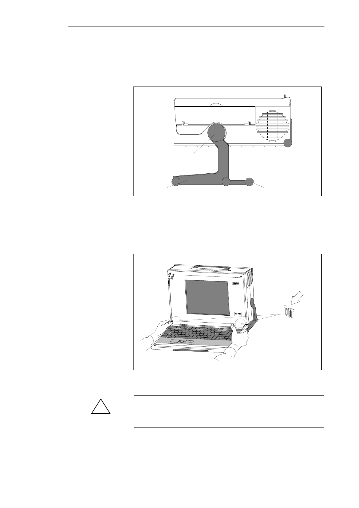
If you do not have a desk or table on which to mount the unit, you can work
with it standing on the floor. You can swing the casing with display through
about 90° into the horizontal plane.
Pivot
Stand
Figure 2-3 Horizontal Operating Position without Keyboard
You can remove the keyboard if you are operating the unit in the position
shown in Fig. 2-3.
Extra pull-out support
2-4
Press down on the locks in
the middle of the hinge
assembly
Figure 2-4 Detaching the Keyboard
Caution
!
If the keyboard is detached, there is a risk of the unit falling over. Pull out
the extra support.
Programming Device PG 740
C79000-G7076-C742-01

Installing the PG 740
You detach the keyboard as follows:
1. Grip the keyboard hinges in the stand behind the keyboard as shown in
Figure 2-4.
2. Pull the locks in the middle of the hinge assembly toward the keyboard.
3. Pull the keyboard up and out.
4. Set the keyboard down on a suitable surface, using the hinge assembly as
a stand.
5. Make sure the cable is not pinched or squashed in any way.
6. T o attach the keyboard again, snap the keyboard hinges into the matching
receptacles in the stand.
2
Wall Mounting
The basic unit can be attached to a wall. Four drilled holes (6 mm diameter)
are provided in the base of the unit for this purpose.
ø6
83 mm
345 mm
Figure 2-5 Drilling Template for Wall Mounting
Programming Device PG 740
C79000-G7076-C742-01
2-5
Installing the PG 740
2.2 Hardware Components of the PG 740
2
Front
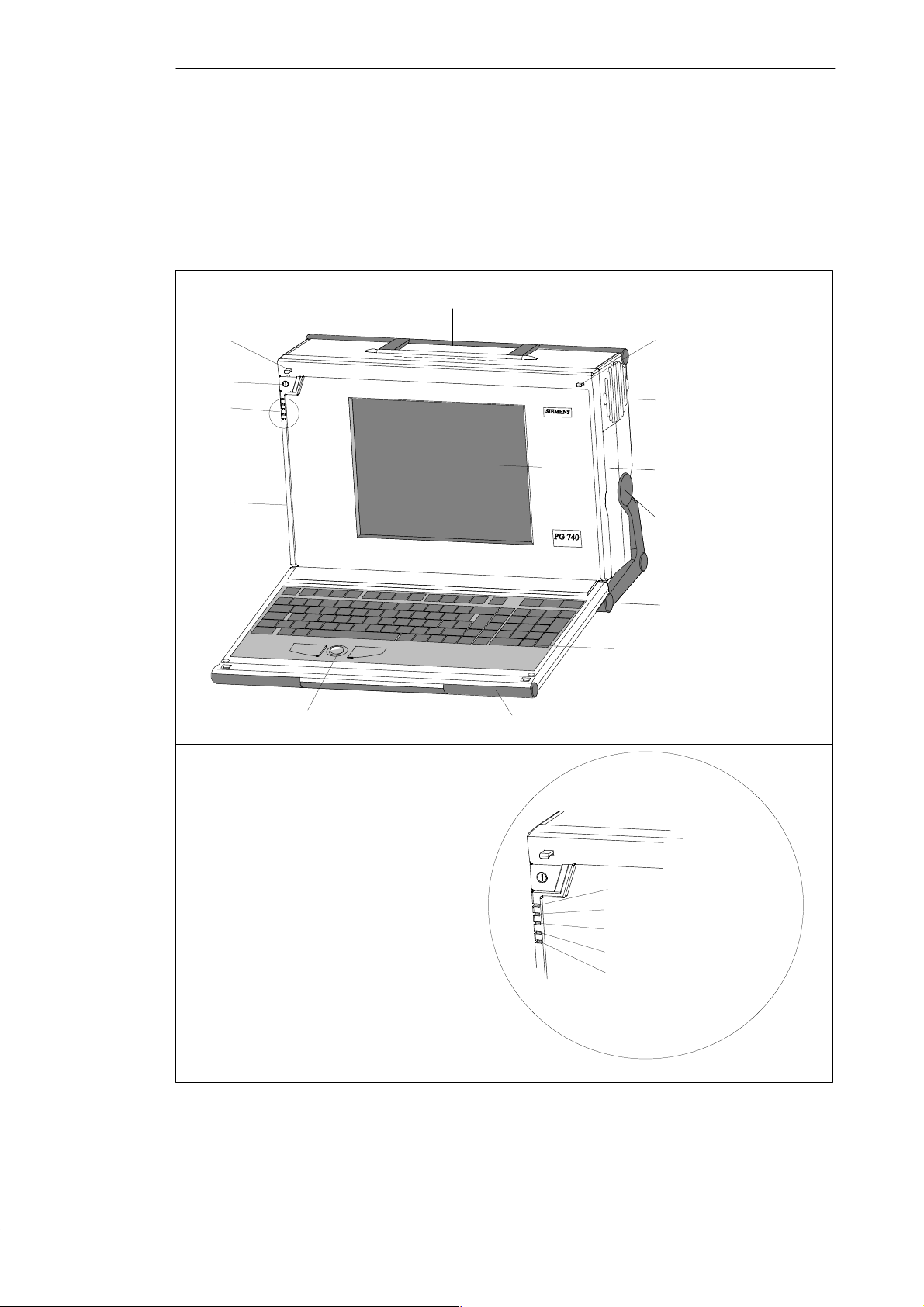
You can access all important operator controls and displays from the front or
sides of the unit.
2
10 10
1
13
3
8
4
5
11
6
7
9
1 On/Off switch
2 Carrying handle
3 LC display
4 Ventilating slots
5 Cover for submodule, memory card, PCMCIA
interfaces and floppy disk drive
6 Stand
7 Keyboard
8 Cover for VGA, COM1, COM2, MPI,
LPT1/printer and mouse interfaces
9 T rackball
10 Catches for locking keyboard
11 Pivot
12 Protector strip
1) The coverplates are used to protect the interface ports from dust,
and can be detached and snapped back on.
Figure 2-6 The Front of the PG 740
1)
1)
2-6
12
LED displays
13
Power
Hard disk access
Floppy access
Submodule programming active
MPI/DP interface
Programming Device PG 740
C79000-G7076-C742-01

pp
Installing the PG 740
Left Hand Casing
Side Panel
(Communications
Side)
All the connectors and interface ports for connecting to external devices are
located on the left-hand side panel of the PG 740 (communications side).
VGA port
Power switch
Dummy plates
covering
expansion slots
Power supply
connector socket
Figure 2-7 Left-Hand Casing Side Panel with Coverplates Removed
LEDs
COM2/V .24 interface
COM1/V .24 interface
MPI/DP
LPT
PS/2 mouse
2
Connectors and
Ports
The following table contains an overview of the various interface ports and
connectors:
Ports and Connectors Function
VGA port Connection for external monitor
Serial port
COM2
V.24/mouse
Serial port
COM1
V.24/MODEM/PLC
Serial port
MPI /DP
(Multipoint interface/
distributed I/Os)
LPT1 Printer
Parallel interface
PS/2 mouse Connection for PS/2 mouse
Connector for power supply Connection for power supply
Connection for serial mouse
Connection for serial printer
Connection for S5 programmable
controller
Connection for S7 programmable
controller and for distributed I/Os
Connection for parallel printer
Programming Device PG 740
C79000-G7076-C742-01
2-7
Installing the PG 740
2
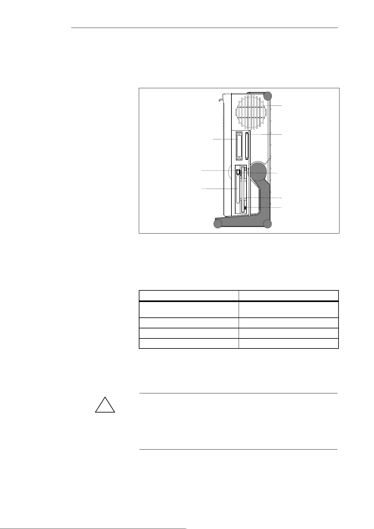
Right-Hand Casing
Side Panel
(Processing Side)
You access the slots for S5/S7 memory submodule programming, the
PCMCIA port and the disk drive from the right-hand side panel of the
PG 740’s casing (processing side).
Ventilating slots
S5 EPROM/EEPROM port
Ejector for PCMCIA
cards
PCMCIA port
Figure 2-8 Right-Hand Casing Side Panel
Memory card port
Ejector for disk
3.5 in. disk drive
Access LED
Ventilating Slots
!
The following table contains an overview of the various interface ports and
connectors:
Interface Port Function
S5 module interface Programming of SIMATIC S5 memory
submodules
Memory card interface Programming of SIMATIC memory cards
PCMCIA port Connection for PCMCIA cards
Disk drive Processing of 3.5 in. disks
The raised air outlet slots for ventilation are located above the interface ports.
There are also ventilating slots on the underside of the base. These slots must
not be covered or blocked in any way (by carpeting, for instance).
Caution
Risk of overheating!
If you cover up the slots for the inlet and outlet air in any way, there is a risk
that your PG 740 will be damaged.
Do not place any objects over, or lay them on, the ventilating slots.
2-8
Programming Device PG 740
C79000-G7076-C742-01
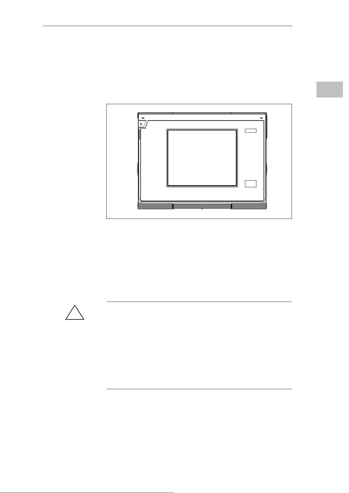
2.3 Display
Installing the PG 740
The PG 740’s Color
Display
Color Shades
The PG 740 has a TFT (thin-film transistor) color display with a 10.4 in.
diagonal and a resolution of 800 x 600 pixels.
Figure 2-9 The PG 740’s Color Display
The three primary colors, red, green and blue, can each be displayed in six
different shades. This means that, including all secondary colors formed, a
maximum of 65535 from 262144 different colors can be displayed, where the
number of colors can be set in the respective graphic driver The display has
automatic contrast control.
2
!
Programming Device PG 740
C79000-G7076-C742-01
Caution
Risk of injury!
If a display is damaged, liquid crystal may escape. Do not touch this liquid
or allow it to come into contact with your skin in any way, and do not
breathe in the vapors. If you do come into contact with the liquid, wash
those parts of the skin affected immediately with alcohol, and rinse with
plenty of water. Then consult a physician right away.
Use only a cotton cloth and a neutral cleansing agent to clean the display. Do
not use water or aggressive solvents (like alcohol or acetone, for instance).
Never touch the display with hard, pointed objects.
2-9
Installing the PG 740
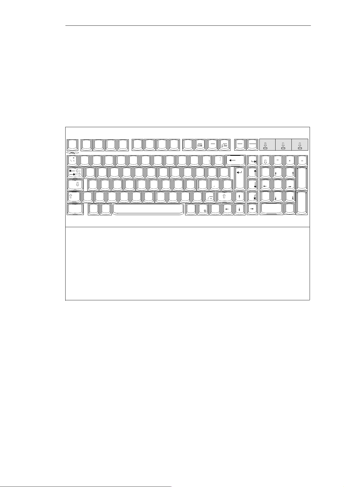
2.4 Keyboard
2
Keyboard Layout
1
F1 F2 F3 F4 F5 F6 F7 F8 F9
Esc
!
~
Caps
Lock
Ctrl Alt
@ ”
1234567{890- ß
QWE RTY U IO P Ü
@
ASDFGH JK L
>
Y
Z
<
F
n
$ % ^ & & / * ( ( ) ) = __?
# w
XC BN
2
1
Function keys
2
Typewriter or alphanumeric keyboard
3
Cursor control keys
Numeric keypad
4
5 Numeric block active
Uppercase active
6
7 Scroll lock active
The keyboard is divided into the following three areas:
S Alphanumeric or typewriter keyboard
S Numeric keypad with cursor control keys
S Function keys
F10
F11
kkk
+
:
Ö
;
Insert
{
[
”
Delete
=
Ä
[
V
M
}
< ;,> :.?
Alt
Gr
Print Pause
F12
}
*
~
+
]
|
’
#
\
SysRq
Break
Home
Page
Page
End
3
67
5
Num Scroll
Num
.
.
7
89
5
2
Page
6
3
Page
.,
Del
Home
4
1
End
0
Ins
4
+
Enter
Figure 2-10 Keyboard
Setting Up the
Keyboard
2-10
All keys on the keyboard are of the autorepeat type. That is, the relevant
character is repeated as long as you keep the key depressed.
When the keyboard is attached to the casing, it has an inclination of 6°, and
the middle row of keys is at a height of 30 mm. When the keyboard is
detached from the casing, its angle of inclination is 4.5° and the middle row
of keys is at a height of 27 mm. Ergonomically, these are the ideal positions
for the keyboard.
Programming Device PG 740
C79000-G7076-C742-01
Installing the PG 740
Typewriter or
Alphanumeric
Keyboard
Keyboard Labeling
The largest block of keys on the keyboard is the alphanumeric or typewriter
keyboard with all the keys for the letters of the alphabet, numerals and
special characters. The characters (letters, numerals and special characters)
are arranged in generally the same way as on a normal typewriter. However,
there are a number of special keys which have specific special functions for
the PG 740.
The keyboard has international labeling.
International
Shift
Unshift
Figure 2-11 The Keyboard Labeling System
National
?
\
ß
Example: German
Font size and thickness
reduced
Together with the
key
ALT
GR
2
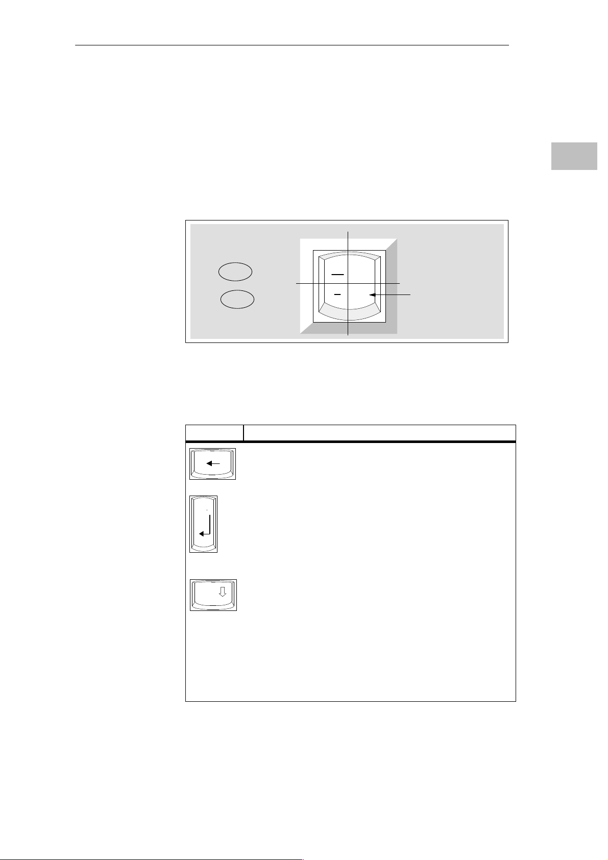
Special Keys
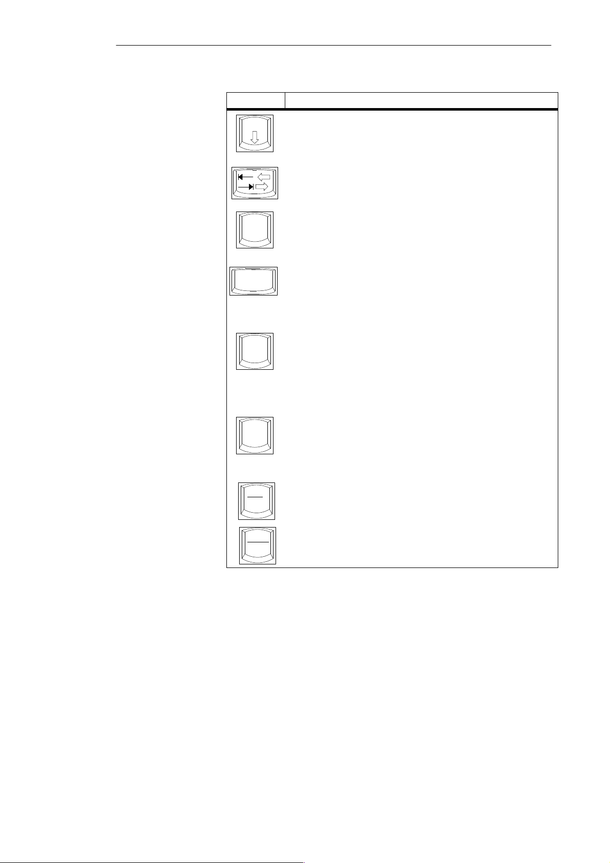
The special keys in the alphanumeric keyboard have the following functions:
Key Function
Backspace Key
This key moves the cursor one space to the left and deletes the
character at this position
Return Key
The Return or Enter key is used mainly to terminate a command
line in the operating system; that is, the command you have
typed in is executed when you press this key. For other uses of
this key, please refer to the user manual of the relevant
application program.
Caps
Lock
CAPS-LOCK Key
If you press this key, the middle LED at the top right-hand corner
of your keyboard lights up. All letters then appear in uppercase
and the upper of the two characters on the individual keys
applies. If you wish to type in lowercase letters in this position,
you must first strike the Shift key.
If you are using an international keyboard, you cancel this
function by pressing the CAPS-LOCK key again. The LED goes
out. If you have a German keyboard, you must strike the Shift
key to cancel this function.
Programming Device PG 740
C79000-G7076-C742-01
2-11
2
Installing the PG 740
Key Function
NUM Key
NUM
F
Ctrl
Alt
Alt
Gr
You switch from the numeric block to cursor control with this key
(Num LED lights up). Press the key again to return to cursor
control.
T abulator Key
This key moves the cursor by one or more positions to the right.
“Fn” Special key (combination key)
n
Together with a second key (key combination), you activate other
key codes for specific applications with this key (see Fig. 2-13
Function Keys).
CTRL Key (combination key)
This key is only used in combination with other keys. For
example, you press Ctrl + AL T + DEL to reset and restart the
operating system. For other uses of this key , please refer to the
user manual of the relevant application program.
ALT Key (combination key)
This key is only used in combination with other keys. For
instance, you can enter the hexadecimal value of an ASCII
character (and consequently additional special characters) using
this key and the numeric keypad.
ALT + 123 corresponds to ”{”.
ALTGr Key (combination key)
You can use this key together with the other combination keys to
generate other key codes. For example, you can generate the ”\”
character on the German keyboard by striking AL T
Gr
+ ß.
Location and
Labeling of the
LED
2-12
Print
SysRq
Pause
Break
PRINT Key (combination key)
You can output the current screen display to a printer by pressing
the PRINT key.
PAUSE Key (combination key)
The P AUSE key interrupts program execution in the majority of
applications.
There are three LEDs on the keyboard. They are located to the right of the
function keys in the top row of the keyboard directly above the numeric
keypad.
S NUM LOCK
S CAPS LOCK
S SCROLL LOCK
When the programming device is powered up, the NUM LOCK, CAPS LOCK
and SCROLL LOCK LEDs light up briefly twice. The keyboard is then ready
for operation.
Programming Device PG 740
C79000-G7076-C742-01
Installing the PG 740
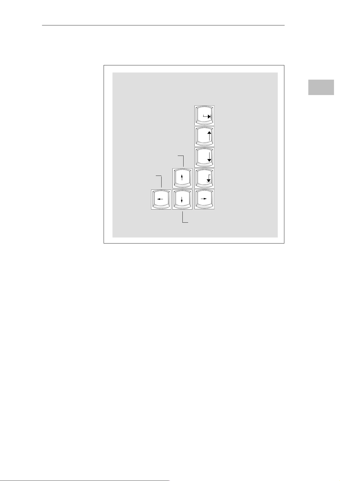
Cursor keys
The keyblock shown below is used for cursor control.
Move cursor up
Move cursor left
Home
Page
Page
End
Move cursor to
beginning of file
Page back
Page forward
Move cursor to end of file
Move cursor right
2
Figure 2-12 Cursor Control Keypad
Move cursor down
Programming Device PG 740
C79000-G7076-C742-01
2-13
Installing the PG 740
2
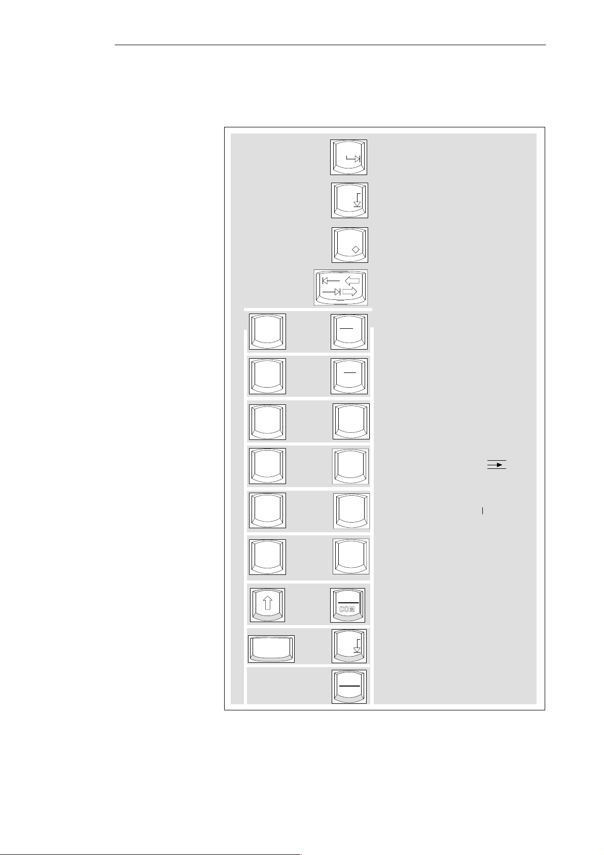
Keys for Functions
Specific to S5
The following function keys have specific functions in conjunction with the
STEP 5 programming software (see STEP 5 Manual).
Home
Horizontal expand
End
Insert
F
n
F
n
+
+
F10
COM
F11
kkk
Vertical expand
Enter key
Cursor right/
cursor left
Title/comment input
for segment
End of segment
F
n
F
n
F
n
F
n
CTRL
+
+
+
+
+
F1
F2
F3
F4
F10
End
Pause
Break
Help
Insert segment
Delete segment (X
Edit mode (CORR)
Zoom (with Graph 5)
Zoom (with Graph 5)
Half screen (with Graph 5)
)
2-14
Figure 2-13 Function Keys (STEP 5)
Programming Device PG 740
C79000-G7076-C742-01
Installing the PG 740
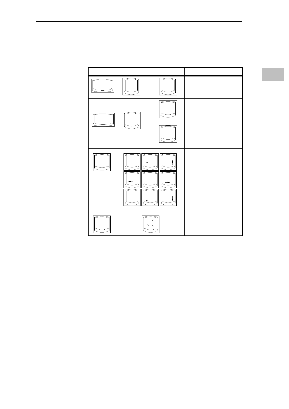
Key Combinations
The various key combinations are shown in T able 2-1.
Table 2-1 Key Combinations
Key Combination Function
CTRL
CTRL
F
n
+
+
+
Alt
Alt
7
Home
4
+
DEL
F1
+
F2
89
Page
5
6
Warm restart
Changeover to international
character set
Changeover to German
character set; the German
character set must have already
been loaded.
By pressing the Fn key and a
cursor control key in the
numeric keypad
simultaneously, you can
change over to the cursor
control functions of the key.
2
LEDs
1
End
F
n
+
2
~
3
Page
Trackball active/passive
The LEDs for the NUM LOCK, CAPS LOCK and SCROLL LOCK keys are
located at the top right of the keyboard, and indicate the current status of
these keys.
Programming Device PG 740
C79000-G7076-C742-01
2-15

Installing the PG 740
2.5 Trackball
2
Trackball
Cleaning the
Trackball
The trackball serves as an input device for cursor control and menu selection
in many programs (with mouse operation). By moving the trackball, the
cursor can be repositioned on the screen.
By pressing the left-hand button, you set a marker. The right-hand button is
assigned differently according to the application. You can select objects or
items in a menu, and start functions with the trackball.
The trackball runs in a self-cleaning roller housing which is capable, under
normal conditions, of preventing dust collecting on the trackball and transfer
mechanism. However, you should clean the trackball from time to time.
Proceed as follows:
1. Switch off your programming device.
2. Remove the cover of the trackball housing by turning it counterclockwise;
for example, by inserting tweezers or a similar gadget in the holes in the
ring.
3. You can now lift the trackball out of its housing.
4. Wash the trackball with tap water to which a mild cleansing agent has
been added (Figure 2-14).
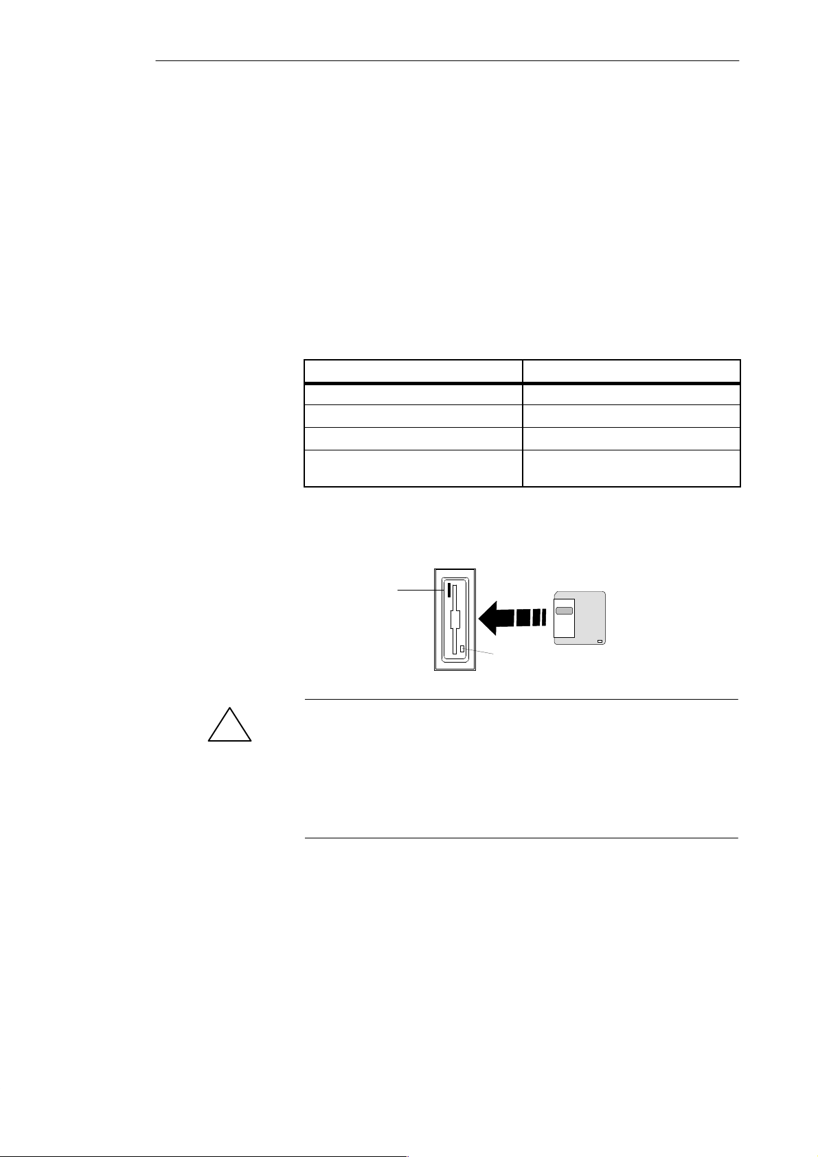
5. Clean the trackball housing (Figure 2-15).
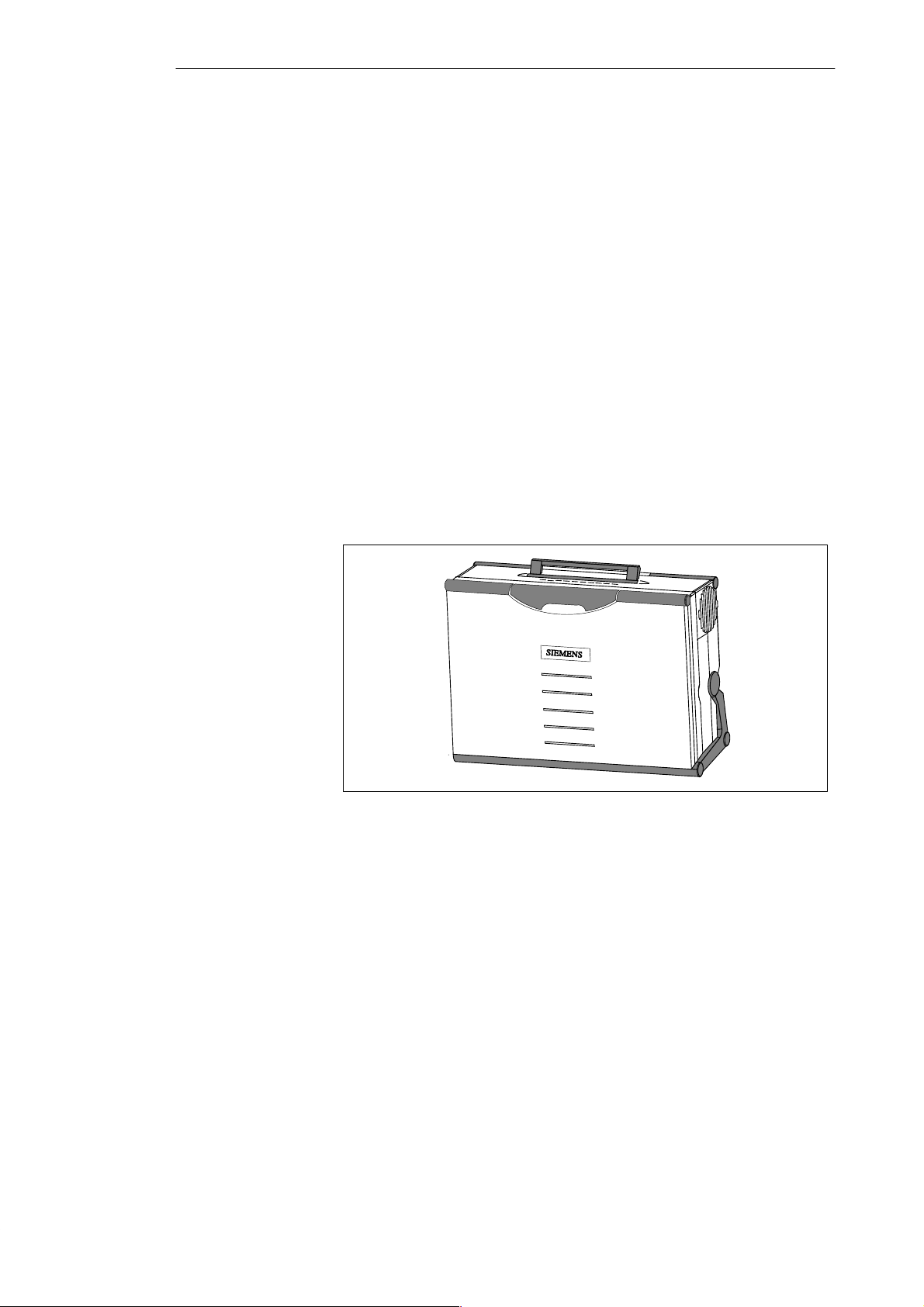
6. Clean the rollers (Figure 2-16).
7. Dry the trackball and return it to its housing.
8. Replace the cover and tighten it by screwing it clockwise.
2-16
Programming Device PG 740
C79000-G7076-C742-01
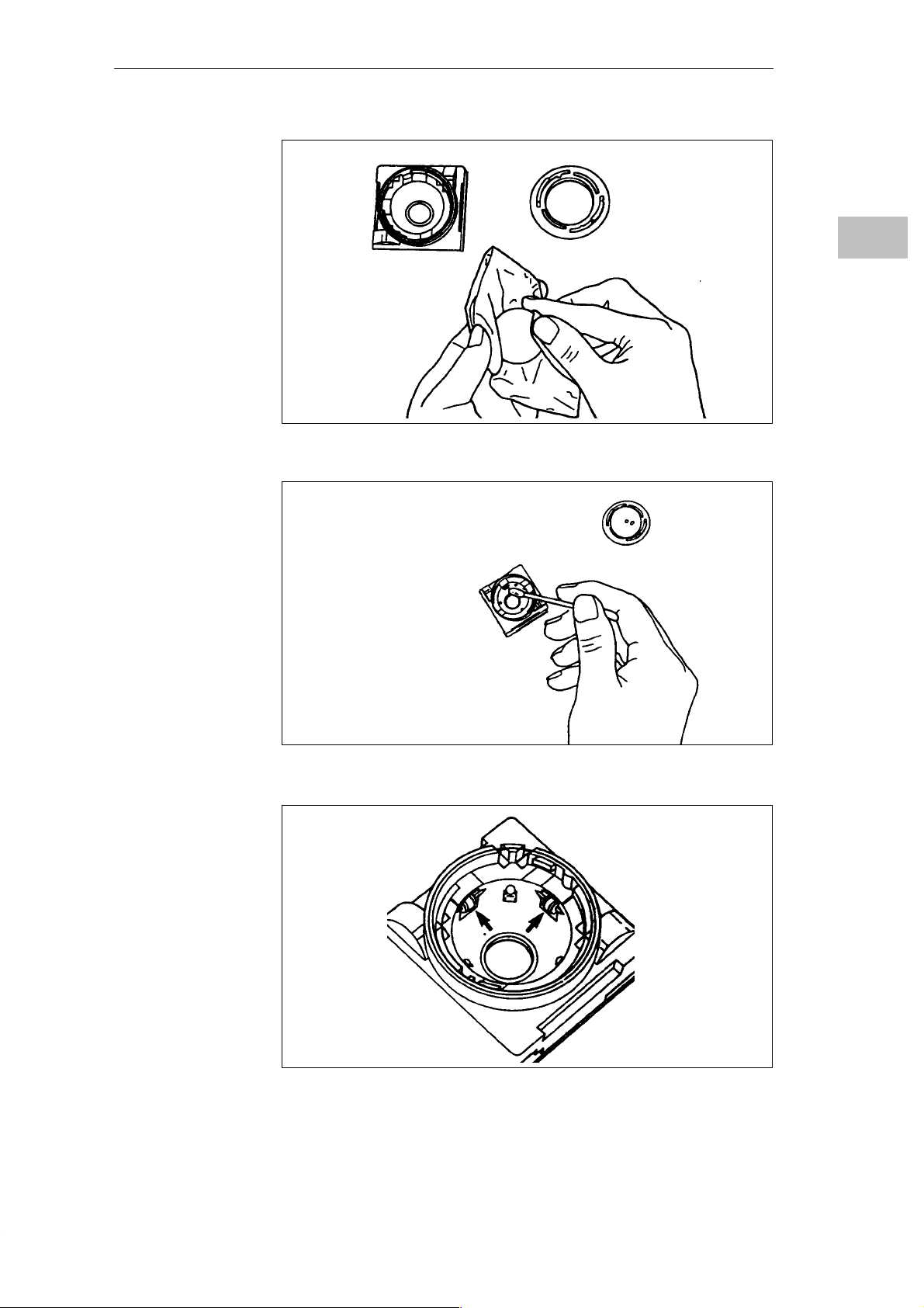
Figure 2-14 Cleaning the Trackball
Installing the PG 740
2
Programming Device PG 740
C79000-G7076-C742-01
Figure 2-15 Cleaning the Trackball Housing
Figure 2-16 Cleaning the Rollers
2-17
Installing the PG 740
2.6 Drives
2
Drive Types
Diskette Drive
Types of Diskette
Handling Diskettes
The PG 740 is equipped as standard with a 3.5” diskette drive and a 3.5” hard
disk drive.
You can store programs and data on diskettes with the diskette drive and load
them from diskettes into the PG 740.
You can use the following diskettes:
Double-Sided High-Density Diskette Double-Sided Double-Density Diskette
3.5 in. 3.5 in.
1.44 MB (135 TPI) 720 KB
80 tracks per side 80 tracks per side
Programming device recognizes diskettes
by their coding
The diskette is inserted in the diskette drive as shown below:
Ejector
Programming device recognizes diskettes
by their coding
!
Hard Disk Drive
2-18
Access LED
Caution
Risk of data loss!
You must not remove the diskette as long as the access LED is lit.
Otherwise, you may lose the data on the diskette.
Do not remove the diskette until the access LED on the drive or on the front
of the PG 740 has gone out.
You can use a number of different hard disk drives in your PG 740. The
memory capacity of the particular type of hard disk can be found in the
Product Information Bulletin and SETUP program.
Programming Device PG 740
C79000-G7076-C742-01

Installing the PG 740
Self-Test
Every time the PG 740 is switched on or reset, the hard disk drive performs a
self-test, which is repeated during operation.
Whenever the hard disk drive is accessed, the access LED on the front of the
unit lights up.
2
Caution
!
Risk of data loss and damage to drive!
Drives are sensitive to vibrations and shock. Any vibrations occurring during
operation can lead to the loss of data or damage to the drive.
If you intend transporting the unit, switch it off, and wait until the drive has
come to rest (about 20 seconds) before you move it.
Programming Device PG 740
C79000-G7076-C742-01
2-19
Installing the PG 740
2.7 Transport
2
Preparatory
Measures
The PG 740 is easy to transport. Before transporting it, however, you should
take the following measures:
1. Switch the PG 740 off.
2. Unplug all connecting cables.
3. Close the covers protecting the ports and connections on the right-hand
and left-hand casing side panels.
4. Bring the unit into an upright position.
5. Swing the keyboard up and press it against the front plate of the unit.
Make sure that the latches on the left and right sides snap in.
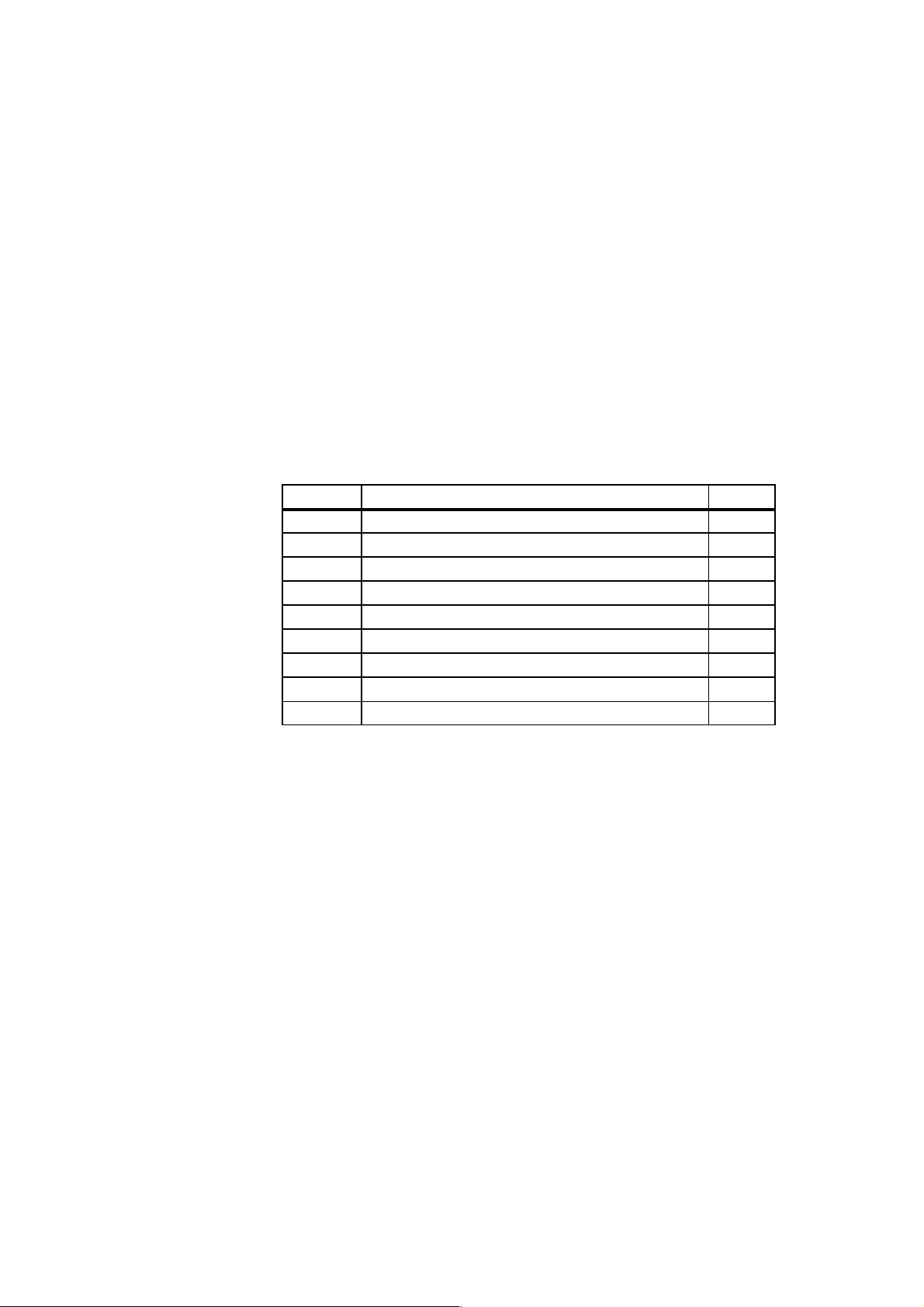
6. Use the carrying handle if you only intend transporting the unit over a
short distance.
7. If you are transporting the PG 740 over large distances, pack the unit with
all its accessories in the carrying bag supplied.
Transport
2-20
Figure 2-17 Prepared for Transport
Despite the fact that the PG 740 is of rugged design, its internal components
are sensitive to severe vibrations or impact. You must therefore protect your
PG 740 against severe mechanical stressing when transporting it.
Use the original packing material if you have to ship the PG 740 from one
location to another.
Programming Device PG 740
C79000-G7076-C742-01

Installing the PG 740
Caution
!
Risk of mechanical damage!
Moisture or condensation in the unit can result in defects.
When transporting your PG 740 in cold weather when it may be exposed to
extreme variations in temperature, make sure that no moisture or
condensation can form on or in the unit.
The unit should be allowed to reach room temperature slowly before it is
started up. If condensation has formed, the unit should be left for about 12
hours (with a temperature difference of -20° C to +20° C (–4° F to +68° F))
before being switched on.
2
Programming Device PG 740
C79000-G7076-C742-01
2-21
Starting Up the PG 740
3
What does this
Chapter Contain?
Summary of
sections
This chapter describes what you have to do to set up your PG 740
successfully for operation. This includes
S the basic steps for starting up your PG 740
S working with memory submodules and cards for the programmable
controllers
S connecting your PG 740 to other devices.
In Section You Will Find On Page
3.1 Connecting the PG 740 to the Power Supply 3-2
3.2 Connecting I/O Devices 3-3
3.3 Working with SIMATIC S5 Memory Submodules 3-9
3.4 Working with SIMATIC Memory Cards 3-10
3.5 Working with PCMCIA Cards 3-11
3.6 PG 740 Connections (Point-To-Point Connections) 3-12
3.7 Multipoint Interface (MPI/DP) 3-16
3.8 SINEC L2 3-18
3.9 SINEC H1 3-19
Programming Device PG 740
C79000-G7076-C742-01
3-1
 Loading...