

Page 1

SIMATIC
Process Control System PCS 7
SMART
PCS 7 SMART Getting Started Part 1 (V9.0 with APL)
Security information
1
Getting Started
Preface
Requirements for Getting
Started
PCS 7 SMART overview
Initial work for the project
Creating CFCs
Creating SFCs
Compiling, downloading and
testing the charts
Configuring the operator
station
2
3
4
5
6
7
8
9
Working in runtime
Performing the additional task
Starting and adapting the
color_gs project
10
11
12
12/2017
A5E42181435-AA
Page 2
Legal information
Warning notice system
This manual contains notices you have to observe in order to ensure your personal safety, as well as to prevent
damage to property. The notices referring to your personal safety are highlighted in the manual by a safety alert
symbol, notices referring only to property damage have no safety alert symbol. These notices shown below are
graded according to the degree of danger.
DANGER
indicates that death or severe personal injury will result if proper precautions are not taken.
WARNING
indicates that death or severe personal injury may result if proper precautions are not taken.
CAUTION
indicates that minor personal injury can result if proper precautions are not taken.
NOTICE
indicates that property damage can result if proper precautions are not taken.
If more than one degree of danger is present, the warning notice representing the highest degree of danger will be
used. A notice warning of injury to persons with a safety alert symbol may also include a warning relating to property
damage.
Qualified Personnel
The product/system described in this documentation may be operated only by personnel qualified for the specific
task in accordance with the relevant documentation, in particular its warning notices and safety instructions. Qualified
personnel are those who, based on their training and experience, are capable of identifying risks and avoiding
potential hazards when working with these products/systems.
Proper use of Siemens products
Note the following:
WARNING
Siemens products may only be used for the applications described in the catalog and in the relevant technical
documentation. If products and components from other manufacturers are used, these must be recommended or
approved by Siemens. Proper transport, storage, installation, assembly, commissioning, operation and
maintenance are required to ensure that the products operate safely and without any problems. The permissible
ambient conditions must be complied with. The information in the relevant documentation must be observed.
Trademarks
All names identified by ® are registered trademarks of Siemens AG. The remaining trademarks in this publication
may be trademarks whose use by third parties for their own purposes could violate the rights of the owner.
Disclaimer of Liability
We have reviewed the contents of this publication to ensure consistency with the hardware and software described.
Since variance cannot be precluded entirely, we cannot guarantee full consistency. However, the information in
this publication is reviewed regularly and any necessary corrections are included in subsequent editions.
Siemens AG
Division Process Industries and Drives
Postfach 48 48
90026 NÜRNBERG
GERMANY
A5E42181435-AA
Ⓟ 11/2017 Subject to change
Copyright © Siemens AG 2017.
All rights reserved
Page 3

Table of contents
1 Security information......................................................................................................................................9
2 Preface.......................................................................................................................................................11
3 Requirements for Getting Started...............................................................................................................17
3.1 Hardware requirements for Getting Started - Part 1..............................................................17
3.2 Software requirements for Getting Started - Part 1................................................................18
3.3 Required configuration for Getting Started - Part 1................................................................19
4 PCS 7 SMART overview............................................................................................................................21
4.1 PCS 7 SMART overview........................................................................................................21
4.2 PCS 7 SMART inclusions......................................................................................................22
4.3 Introduction to SIMATIC Manager..........................................................................................23
4.4 Basic Structure of SIMATIC Manager....................................................................................24
4.5 Different views of SIMATIC Manager.....................................................................................25
4.6 Procedure...............................................................................................................................26
4.6.1 Opening SIMATIC Manager...................................................................................................26
5 Initial work for the project............................................................................................................................27
5.1 Planning the project...............................................................................................................27
5.1.1 The "color_gs" project............................................................................................................27
5.1.2 Task list for Getting Started....................................................................................................28
5.1.3 System configuration for the 'color_gs' project.......................................................................30
5.1.4 Configuration tasks overview.................................................................................................31
5.2 Preparational settings for the network....................................................................................32
5.2.1 Network and Interface settings...............................................................................................32
5.2.2 Procedure...............................................................................................................................32
5.2.2.1 Configuration console settings...............................................................................................32
5.3 Creating the project................................................................................................................34
5.3.1 "New Project" Wizard usage..................................................................................................34
5.3.2 Background knowledge for the PCS 7 Wizard.......................................................................34
5.3.3 Procedure...............................................................................................................................36
5.3.3.1 Creating the color_gs Project.................................................................................................36
5.3.3.2 Opening and Closing the "color_gs" Project..........................................................................39
5.3.3.3 How to Work in the Various Views.........................................................................................39
5.4 Configuring the stations.........................................................................................................41
5.4.1 Configuration overview...........................................................................................................41
5.4.2 Procedure...............................................................................................................................42
5.4.2.1 AS configuration.....................................................................................................................42
5.4.2.2 Renaming the PC Station.......................................................................................................44
5.4.2.3 Configuring the PC station of the OS.....................................................................................45
5.4.2.4 NetPro settings.......................................................................................................................47
PCS 7 SMART Getting Started - Part 1 (V9.0 with APL)
Getting Started, 12/2017, A5E42181435-AA 3
Page 4

Table of contents
5.4.2.5 Configuring and downloading the PC station of the OS.........................................................49
5.4.2.6 Downloading the hardware configuration of the AS...............................................................50
5.5 Working in the plant hierarchy................................................................................................52
5.5.1 Introduction to plant hierarchy................................................................................................52
5.5.2 Plant hierarchy settings..........................................................................................................52
5.5.3 Plant view structure................................................................................................................54
5.5.4 Adapting default names.........................................................................................................54
5.5.5 Inserting additional hierarchy folders.....................................................................................57
5.5.6 Checking the assignment of AS/OS to the plant hierarchy....................................................58
5.6 Current status.........................................................................................................................59
5.6.1 Current state of your project...................................................................................................59
6 Creating CFCs............................................................................................................................................61
6.1 CFC Charts and the CFC Editor............................................................................................61
6.2 Working with libraries.............................................................................................................62
6.2.1 CFC Charts and the master data library................................................................................62
6.2.2 Storing objects in the master data library...............................................................................62
6.2.3 Working with the master data library......................................................................................63
6.2.4 Opening the libraries..............................................................................................................64
6.2.5 Storing blocks.........................................................................................................................65
6.2.6 Storing process tag types.......................................................................................................67
6.2.7 Showing and hiding libraries..................................................................................................68
6.2.8 Process to hide and show libraries........................................................................................69
6.3 Technological significance of the charts in the project...........................................................71
6.3.1 Charts in "color_gs" project....................................................................................................71
6.3.2 Process-Related meaning of the "CFC_SETP" CFC chart....................................................71
6.3.3 Process-Related meaning of the "CFC_FC111" CFC chart...................................................72
6.3.4 Process-Related meaning of the "CFC_LI111" CFC chart.....................................................72
6.3.5 Process-Related meaning of the "CFC_NP111" CFC chart...................................................72
6.3.6 Process-Related meaning of the "CFC_NK11x" CFC chart...................................................73
6.4 CFCs in the Plant Hierarchy...................................................................................................74
6.4.1 Working with CFC charts.......................................................................................................74
6.4.2 Procedure...............................................................................................................................74
6.4.2.1 Renaming CFC charts in the Plant Hierarchy........................................................................74
6.4.2.2 Inserting new CFC charts in the Plant Hierarchy...................................................................75
6.4.2.3 Inserting the "Motor_Lean" process tag type.........................................................................76
6.5 The current status..................................................................................................................77
6.5.1 Current status of your project.................................................................................................77
6.6 Working with the CFC Editor..................................................................................................78
6.6.1 Introduction to the CFC Editor................................................................................................78
6.6.2 CFC Chart in the CFC Editor.................................................................................................78
6.6.3 Catalog in the CFC Editor......................................................................................................79
6.6.4 Configuration steps for CFC charts overview.........................................................................80
6.6.5 Opening the "CFC_SETP" CFC chart....................................................................................80
6.6.6 Assignment of block parameters in CFC charts.....................................................................81
6.6.7 Inserting the blocks into the "CFC_SETP".............................................................................81
6.6.8 Assigning parameters for the blocks in "CFC_SETP"............................................................82
6.6.9 Inserting the blocks into the "CFC_FC111"............................................................................84
6.6.10 Assigning parameters for the blocks in the "CFC_FC111".....................................................85
PCS 7 SMART Getting Started - Part 1 (V9.0 with APL)
4 Getting Started, 12/2017, A5E42181435-AA
Page 5

Table of contents
6.6.11 Inserting the blocks in the "CFC_LI111".................................................................................88
6.6.12 Assigning parameters for the blocks in the "CFC_LI111"......................................................89
6.6.13 Assigning Parameters for blocks in the "CFC_NP111"..........................................................91
6.6.14 Interconnection of blocks in the CFC charts..........................................................................92
6.6.15 Interconnecting blocks in the "CFC_NP111"..........................................................................93
6.6.16 Interconnecting blocks in the "CFC_FC111"..........................................................................94
6.6.17 Interconnecting blocks in the "CFC_LI111"............................................................................95
6.6.18 Assigning parameters for the blocks in "Valve_Lean"............................................................96
6.6.19 Interconnecting the blocks in "Valve_Lean"...........................................................................97
6.7 CFCs in the process object view............................................................................................98
6.7.1 Use of the Process Object View for valve control..................................................................98
6.7.2 Procedure...............................................................................................................................98
6.7.2.1 Defining Inputs/Outputs for the Process Object View............................................................98
6.7.2.2 Inserting the "Valve_Lean" process tag type........................................................................100
6.7.2.3 Adapting the parameters for "CFC_NK11x".........................................................................101
6.7.2.4 Deleting Interconnections to addresses...............................................................................103
6.7.2.5 Selecting block icons............................................................................................................104
6.8 The current status................................................................................................................105
6.8.1 Current status of your project...............................................................................................105
7 Creating SFCs..........................................................................................................................................107
7.1 Overview of Sequential Function Charts (SFCs).................................................................107
7.2 Working with the SFC Editor................................................................................................108
7.2.1 Introduction to the SFC Editor..............................................................................................108
7.2.2 Important functions in the SFC Editor..................................................................................108
7.2.3 Properties of steps and transitions.......................................................................................109
7.2.4 Overview of the configuration steps for SFC charts.............................................................110
7.2.5 Moving an SFC chart...........................................................................................................110
7.2.6 Renaming the SFC chart......................................................................................................111
7.2.7 Opening the "SFC_RMT1" SFC Chart.................................................................................112
7.2.8 Technological structure of the sequential control system....................................................112
7.2.9 Creating the sequential control system in the SFC chart.....................................................113
7.2.10 Renaming steps...................................................................................................................115
7.2.11 Renaming transitions...........................................................................................................117
7.3 Setting parameters...............................................................................................................119
7.3.1 Assigning parameters to the steps of the SFC chart............................................................119
7.3.2 Parameters for the steps......................................................................................................122
7.3.3 Assigning parameters to the transitions of the SFC chart....................................................124
7.3.4 Parameters for the transitions..............................................................................................125
7.3.5 Optimizing the run sequence...............................................................................................127
7.4 The current status................................................................................................................128
7.4.1 Current status of your project...............................................................................................128
8 Compiling, downloading and testing the charts........................................................................................129
8.1 Overview of compiling, downloading, and testing................................................................129
8.2 Procedure.............................................................................................................................130
8.2.1 Compiling and Downloading CFC and SFC charts..............................................................130
8.2.2 Testing the program.............................................................................................................133
8.2.3 Testing the program in the SFC Editor.................................................................................134
PCS 7 SMART Getting Started - Part 1 (V9.0 with APL)
Getting Started, 12/2017, A5E42181435-AA 5
Page 6

Table of contents
8.2.4 Testing the program in the CFC Editor................................................................................135
8.3 The current status................................................................................................................137
8.3.1 Current status of your project...............................................................................................137
9 Configuring the operator station...............................................................................................................139
9.1 Introduction to the OS project editor....................................................................................139
9.2 Operator station in process mode........................................................................................140
9.3 Configuration of the operator station....................................................................................141
9.4 Working in the SIMATIC Manager.......................................................................................142
9.4.1 Preparations in SIMATIC Manager......................................................................................142
9.4.2 Procedure.............................................................................................................................143
9.4.2.1 Editing picture properties.....................................................................................................143
9.4.2.2 Deleting unnecessary pictures.............................................................................................144
9.4.2.3 Creating block icons.............................................................................................................145
9.4.2.4 Compiling the OS.................................................................................................................147
9.4.2.5 Starting the PCS7 SMART OS.............................................................................................150
9.5 Working on the OS...............................................................................................................151
9.5.1 Structure of the OS - WinCC Explorer.................................................................................151
9.5.2 Function of process pictures................................................................................................151
9.5.3 Setting the OS activation for the ES.....................................................................................151
9.6 Working in general with the Graphics Designer...................................................................153
9.6.1 Introduction to the Graphics Designer..................................................................................153
9.6.2 Opening a Process Picture..................................................................................................153
9.6.3 Opening various toolbars.....................................................................................................154
9.6.4 Objects in the Graphics Designer........................................................................................155
9.6.5 Static objects........................................................................................................................156
9.6.6 Text fields.............................................................................................................................156
9.6.7 Working with tag interconnection.........................................................................................156
9.7 Creating the process picture................................................................................................157
9.7.1 Inserting pipes and a tank into the process picture..............................................................157
9.7.2 Labeling the parts of the plant..............................................................................................160
9.7.3 Step 1 - Inserting a text field................................................................................................160
9.7.4 Step 2 - Setting the text field................................................................................................160
9.7.5 Step3 - Duplicating the text field..........................................................................................161
9.7.6 Current status of the process picture...................................................................................163
9.7.7 Adapting process pictures....................................................................................................163
9.7.8 Connecting the raw material tank with the process value....................................................164
9.7.9 Step 3 - Adding explanatory text..........................................................................................167
9.7.10 Step 4 - Configuring the setpoint default..............................................................................168
9.7.11 Completing the work............................................................................................................169
9.8 The current status................................................................................................................170
9.8.1 Current status of your project...............................................................................................170
10 Working in runtime....................................................................................................................................171
10.1 Planning the user interface..................................................................................................171
10.1.1 Operator station in process mode........................................................................................171
10.1.2 User interface in process mode...........................................................................................171
10.2 Operator control and monitoring in process mode...............................................................173
PCS 7 SMART Getting Started - Part 1 (V9.0 with APL)
6 Getting Started, 12/2017, A5E42181435-AA
Page 7

Table of contents
10.2.1 WinCC language settings.....................................................................................................173
10.2.2 Activating process mode......................................................................................................173
10.2.3 Starting the process.............................................................................................................174
10.2.4 Stopping the process...........................................................................................................177
10.2.5 Controlling the process by means of the process picture....................................................177
10.2.6 Specifying the reactor..........................................................................................................177
10.2.7 Opening the faceplates........................................................................................................178
10.2.8 Changing the setpoint..........................................................................................................178
10.2.9 Working with messages.......................................................................................................182
10.2.10 Process mode exit................................................................................................................184
11 Performing the additional task..................................................................................................................185
11.1 Introduction to the additional task........................................................................................185
11.2 Copying the existing 'RMT1' part of the plant.......................................................................186
11.3 Process mode preparation...................................................................................................188
11.4 Compile and download the changes....................................................................................189
11.5 Adapting the OS configuration.............................................................................................194
11.6 Starting process mode.........................................................................................................195
12 Starting and adapting the color_gs project...............................................................................................197
12.1 color_gs project....................................................................................................................197
12.2 Procedure.............................................................................................................................198
12.2.1 Opening the color_gs project...............................................................................................198
12.2.2 Adapting the hardware for the color_gs project....................................................................198
12.2.3 Adapting the blocks for the color_gs project........................................................................199
12.2.4 Adapting the project data for the color_gs project................................................................200
12.2.5 Compiling and downloading the color_gs project.................................................................201
Index.........................................................................................................................................................205
PCS 7 SMART Getting Started - Part 1 (V9.0 with APL)
Getting Started, 12/2017, A5E42181435-AA 7
Page 8

Table of contents
PCS 7 SMART Getting Started - Part 1 (V9.0 with APL)
8 Getting Started, 12/2017, A5E42181435-AA
Page 9

Security information
Siemens provides products and solutions with industrial security functions that support the
secure operation of plants, systems, machines, and networks.
In order to protect plants, systems, machines and networks against cyber threats, it is
necessary to implement – and continuously maintain – a holistic, state-of-the-art industrial
security concept. Siemens’ products and solutions constitute one element of such a concept.
Customers are responsible for preventing unauthorized access to their plants, systems,
machines and networks. Such systems, machines and components should only be connected
to an enterprise network or the internet if and to the extent such a connection is necessary
and only when appropriate security measures (e.g. firewalls and/or network segmentation) are
in place.
For additional information on industrial security measures that may be implemented, please
visit:
https://www.siemens.com/industrialsecurity
Siemens’ products and solutions undergo continuous development to make them more secure.
Siemens strongly recommends that product updates are applied as soon as they are available
and that the latest product versions are used. Use of product versions that are no longer
supported, and failure to apply the latest updates may increase customer’s exposure to cyber
threats.
1
To stay informed about product updates, subscribe to the Siemens Industrial Security RSS
Feed under
https://www.siemens.com/industrialsecurity.
PCS 7 SMART Getting Started - Part 1 (V9.0 with APL)
Getting Started, 12/2017, A5E42181435-AA 9
Page 10

Security information
PCS 7 SMART Getting Started - Part 1 (V9.0 with APL)
10 Getting Started, 12/2017, A5E42181435-AA
Page 11

Preface
About this document
2
Prerequisites
PCS 7 SMART Getting Started - Part 1 (V9.0 with APL)
SMART process control system, enabling you to create a simple project. You can configure
the project on an existing SIMATIC PC station.
PCS 7 SMART is suitable for companies that need cost efficient automation for small plant
configurations.
This Getting Started document is aimed at beginners who work on the following areas:
● Configuration
● Commissioning and service
In the rest of the document, we address the document as
You must have knowledge in the following areas:
● The following Microsoft operating systems:
– Windows 7 Ultimate / Enterprise SP1 (64-Bit)
– Windows 7 Professional SP1 (64-Bit, English version only)
– Windows 10 Enterprise 2015 LTSB (64-Bit)
● Basic knowledge in the field of process automation
● Functions and configuration of SIMATIC S7 (S7-410, STEP 7)
gives you an overview of the PCS 7
Getting Started - Part 1.
● Functions and configuration of SIMATIC NET (network components, transmission media)
Note
● SIMATIC PCS 7 SMART is based on PCS 7 Asia. PCS 7 SMART is specifically designed
for smaller projects with up to 2400 Process Objects (PO) within the Chinese and Indian
markets. With PCS 7 SMART portfolio, we offer a custom-fit product for projects with up to
eight PCS 7 SMART OS Single Stations. Specifically, the combination of SMART software
and SMART hardware increases functionality and, therefore, makes PCS 7 SMART a
suitable software for such projects in China and India.
● PCS 7 SMART does not come with a trial version. A USB hardlock must be plugged in
permanently for configuration and runtime.
PCS 7 SMART Getting Started - Part 1 (V9.0 with APL)
Getting Started, 12/2017, A5E42181435-AA 11
Page 12

Preface
Accessing PCS 7 SMART documentation
You can find the PCS 7 SMART documentation at the following locations:
● On the
● On the computer, in the installation folder
● On the Internet:
– Region India (https://support.industry.siemens.com/cs/in/en/ps/21144)
– Region China (https://support.industry.siemens.com/cs/cn/zh/ps/21144)
In this entry, you can also find the manual on PCS 7 SMART, which shows the differences
between PCS 7 SMART and PCS 7.
Process Control System; SIMATIC PCS 7 SMART
Information about PCS 7 basic system on the Internet
All product and order information regarding PCS 7:
● Internet link (https://www.siemens.com/PCS7)
Overview of the most important technical information and solutions for PCS 7 in the Industry
Online Support:
● Internet link (https://support.industry.siemens.com/cs/document/63481413)
All information on Support and Service in the Industry Online Support:
● Internet link (https://support.industry.siemens.com)
Note
DVD
We recommend you to subscribe to the newsletter, which keeps you constantly updated with
current information about our products.
PCS 7 SMART Getting Started - Part 1 (V9.0 with APL)
12 Getting Started, 12/2017, A5E42181435-AA
Page 13

Contents of the PCS 7 Readme files
The PCS 7 V9.0 SMART Readme file is available in various versions:
1. PCS 7 SMART Readme (offline)
It is installed during the PCS 7 setup and it contains general notes and links to documents
on the internet.
2. PCS 7 SMART Readme (online)
This document contains specific information on the installation and use of PCS 7 SMART.
It is only available on the internet so that we can keep it up to date.
You can download the current version of the document under the entry ID 109744321 in
the Industry Online Support:
Preface
– Region India (
https://support.industry.siemens.com/cs/in/en/view/109744321)
– Region China (https://support.industry.siemens.com/cs/cn/zh/view/109744321)
3. PCS 7 Readme (online)
This document contains general information on the installation and use of PCS 7.
You can download the current version of the document under the entry ID 109744312 in
the Industry Online Support:
– Internet link (https://support.industry.siemens.com/cs/ww/en/view/109744312)
Note
It is vital that you use the information from the most recent version of the SMART and PCS 7
Readme (online) before you begin the installation or use of PCS 7 V9.0 SMART version.
The information in the PCS 7 SMART Readme (online) supersedes the information in the
PCS 7 Readme (online).
Each of the products comes with product-specific information in the form of readme files.
The information contained in these readme files also applies to using products in PCS 7
SMART.
Electronic manuals and help system for the basic system PCS 7
Pre-installed manuals
Once you have installed PCS 7 on your computer, the following PCS 7 documentation is
immediately available.
● You can find this documentation in the section SIEMENS Automation > SIMATIC >
Documentation or the product information in the "Start" menu of Windows:
– PCS 7 - Catalog Overview (PDF)
– PCS 7 - Operating Instructions - OS Process Control (PDF)
– PCS 7 - Installation Manual - PC Configuration (PDF)
– PCS 7 - Configuration Manual - Engineering System (PDF)
– PCS 7 - Configuration Manual - Operator Station (PDF)
PCS 7 SMART Getting Started - Part 1 (V9.0 with APL)
Getting Started, 12/2017, A5E42181435-AA 13
Page 14

Preface
Complete documentation for PCS 7 on the internet and document updates
The complete PCS 7 documentation is available in multiple languages at the following Internet
site:
● Internet link (https://www.siemens.com/pcs7-documentation)
You also have the option of updating the installed PCS 7 help system and post-installing the
PCS 7 system documentation. The "PCS 7 Documentation Portal Setup" required for this is
available for download under the entry ID 109744320 in the Industry Online Support:
● Download link (https://support.industry.siemens.com/cs/ww/en/view/109744320)
Note
Timeliness of online documents
Documents available online may be up-to-date than the version of documents installed with
PCS 7 Setup. The statements in documents available online should therefore be given priority
over installed documents.
Information on modified documents
In order to keep yourself informed about changes to the PCS 7 readme and the other PCS 7
documentation, we recommend that you activate the relevant notification in the Industry Online
Support:
● Internet link (https://support.industry.siemens.com)
Guide
Getting Started - Part 1
You will find important information required to understand the steps in this Getting Started as
well as detailed instructions on how to work through them.
Getting Started - Part 2
you will configure a unit for the color project and become familiar with the functions of rational
engineering.
You can download the completed PCS 7 SMART project color_gs and the documentation
Getting Started - Part 1 and Getting Started - Part 2
● Getting Started - Part 1 (https://support.industry.siemens.com/cs/in/en/view/109751150)
● Getting Started - Part 2 (https://support.industry.siemens.com/cs/in/en/view/109751151)
● To download the project, click the icon:
Open the projects on the Engineering Station (ES) to view the configuration data and compare
the data with your own configuration data. Activate the project on an Operator Station (OS) in
order to operate and monitor the process.
explains the individual steps required to create the color_gs project.
is a continuation of
Getting Started - Part 1
from the internet:
. In this Getting Started,
PCS 7 SMART Getting Started - Part 1 (V9.0 with APL)
14 Getting Started, 12/2017, A5E42181435-AA
Page 15

Conventions
Preface
Note
● To test the color_gs project in process mode, the hardware configuration of the project must
correspond to your actual hardware configuration. If necessary, replace the hardware
components of the color_gs project with the actual hardware components present.
● You will find additional information about opening and adapting the color_gs project in the
"Starting and adapting the color gs project" chapter.
In this document, all the instructions are given using their full menu commands. You can also
access virtually all of the functions through the shortcut menu or by double-clicking.
Note
In this documentation, the versions of profiles, libraries and modules are always displayed as
Vxx.
Ensure that you use an appropriate version for your hardware or software.
Example:
● Profile: PCS7_Vxx
● PCS 7 AP Library Vxx
● IE General: SW Vxx
Note
The names of elements in the software interface are specified in the language of this
documentation. If you have installed a multi-language package for the operating system, some
of the designations will be displayed in the base language of the operating system after a
language switch and will, therefore, differ from the designations used in the documentation.
In PCS 7 SMART, you can use standard Windows functions in many situations:
● Multiple selection using the "Ctrl" and "Shift" keys
● Column sorting in tables by clicking on the column header
● Use of "drag and drop" instead of "copy and paste"
The individual tutorials in this document build on each other to create a complete PCS 7
SMART project step-by-step by working through all the modules in the specified sequence.
For this reason, please work through all the tutorials in the given sequence.
PCS 7 SMART glossary
The PCS 7 SMART glossary containing the definitions of important technical terms used in
the documentation are available within the PCS 7 SMART software through the Help menu in
the SIMATIC Manager ( Help>Contents).
PCS 7 SMART Getting Started - Part 1 (V9.0 with APL)
Getting Started, 12/2017, A5E42181435-AA 15
Page 16

Preface
Additional information
You can find detailed background information and general context in the following
documentation, which you can use for reference purposes:
● Configuration manual
● Configuration manual;
This documentation is available as an online help and in the PDF format.
● Online help
– In the PCS 7 software in SIMATIC Manager, select Help > Topics.
● PDF file
– In the "Start" menu, under the SIEMENS Automation > SIMATIC > Documentation
folder, in the preferred language.
– In the _Manuals folder of the
If you wish to familiarize yourself with specific topics, refer to the appropriate manuals. For
example: SFC and CFC.
; Process Control System PCS 7; Engineering System
Process Control System PCS 7; Operator Station
SIMATIC PCS 7
SMART DVD.
PCS 7 SMART Getting Started - Part 1 (V9.0 with APL)
16 Getting Started, 12/2017, A5E42181435-AA
Page 17

Requirements for Getting Started
3.1 Hardware requirements for Getting Started - Part 1
Hardware components
The list below shows the hardware components you need for Getting Started. For some
hardware components, you must use a specific version because it is not possible to work on
Getting Started with an older version.
Hardware Component Version Used in Getting Started Other Version Possible
PG or PC with a standard
network card
Rack UR2 Yes
Power supply PS 407 4A Yes
CPU CPU 410 SMART Firmware V8.2 Yes
Crossover cable No
USB hardlock PCS 7 SMART V9.0 No (Hardlocks are version
Intel® PRO/1000 Yes
specific)
3
Use of other hardware components
If you are using other hardware components, you must place them in the relevant places. For
example, in HW Config, we recommend the usage of same components that are used in
Getting Started.
If you have different hardware, you can find additional information in the "
Manual
".
ES Configuration
PCS 7 SMART Getting Started - Part 1 (V9.0 with APL)
Getting Started, 12/2017, A5E42181435-AA 17
Page 18

Requirements for Getting Started
3.2 Software requirements for Getting Started - Part 1
3.2 Software requirements for Getting Started - Part 1
Software requirements
● Information about installation and operation of the PCS 7 SMART software is available in
the
Process Control System PCS 7; PCS 7 Readme
● You will find information on the installation of the PCS 7 SMART software in these
documents:
Note
Engineering system
PC stations with a pre-installed Engineering System contain all the necessary software
components. However, you must transfer the license keys to PC stations.
Process Control System PCS 7; PCS 7 PC Configuration
file (see "Preface (Page 11)").
.
PCS 7 SMART Getting Started - Part 1 (V9.0 with APL)
18 Getting Started, 12/2017, A5E42181435-AA
Page 19

Requirements for Getting Started
3.3 Required configuration for Getting Started - Part 1
3.3 Required configuration for Getting Started - Part 1
If you have not purchased a bundle PC with the Getting Started, note the PC settings to be
performed for PCS 7 SMART.
For more information, refer to
Process Control System; PCS 7 PC Configuration
manual.
PCS 7 SMART Getting Started - Part 1 (V9.0 with APL)
Getting Started, 12/2017, A5E42181435-AA 19
Page 20

Requirements for Getting Started
3.3 Required configuration for Getting Started - Part 1
PCS 7 SMART Getting Started - Part 1 (V9.0 with APL)
20 Getting Started, 12/2017, A5E42181435-AA
Page 21

PCS 7 SMART overview
4.1 PCS 7 SMART overview
Description
PCS 7 SMART is a powerful process control system with many automatic functions to assist
you during configuration of a plant. It enables you to create a project quickly and conveniently.
You will get to know about the automatic functions in this Getting Started document. PCS 7
SMART also provides many options for creating individual, project-specific solutions
customized to your requirements. These individual solutions are not part of this Getting Started
document. For more information, refer to the configuration manuals.
A PCS 7 SMART project includes the following objects:
● Hardware configuration
● Blocks
● CFC charts and SFC charts
These objects are always included regardless of the number of operator stations, modules,
and networks.
4
PCS 7 SMART Getting Started - Part 1 (V9.0 with APL)
Getting Started, 12/2017, A5E42181435-AA 21
Page 22

PCS 7 SMART overview
4.2 PCS 7 SMART inclusions
4.2 PCS 7 SMART inclusions
PCS 7 SMART applications
You create a smart project on an Engineering Station (ES), which provides various
applications. All applications have simplified user interface to ease your operations and display
your configuration data. When you work through Getting Started project, you will use the
following applications:
● SIMATIC Manager - the central application and gateway to all other applications that you
use to create a PCS 7 SMART project. SIMATIC Manager is the starting point for creating
your entire project.
● HW Config - used to configure entire hardware of a system, for example, CPUs, power
supply, and communications processors.
● Continuous Function Chart (CFC) and Sequential Function Chart (SFC) Editors - used to
create CFCs and SFCs.
● Operator Station (OS) - used to configure the OS.
PCS 7 SMART Getting Started - Part 1 (V9.0 with APL)
22 Getting Started, 12/2017, A5E42181435-AA
Page 23

4.3 Introduction to SIMATIC Manager
SIMATIC Manager
SIMATIC Manager is the central application within the PCS 7 SMART system and is used to
access all the other applications to configure your PCS 7 SMART project.
SIMATIC Manager and all other applications are linked. For example, all the blocks you have
inserted into a CFC chart using the CFC editor.
This linking provides convenient access to all the data created in SIMATIC Manager and its
applications. For example, you can visualize a process tag from a CFC chart quickly and easily
when configuring the OS.
Due to the central function of SIMATIC Manager within PCS 7 SMART, it is worth taking time
to become familiar with its structure and functions.
PCS 7 SMART overview
4.3 Introduction to SIMATIC Manager
PCS 7 SMART Getting Started - Part 1 (V9.0 with APL)
Getting Started, 12/2017, A5E42181435-AA 23
Page 24

PCS 7 SMART overview
4.4 Basic Structure of SIMATIC Manager
4.4 Basic Structure of SIMATIC Manager
Structure of SIMATIC Manager
SIMATIC Manager has a split window similar to Windows Explorer:
● In the left pane, a tree view is displayed with different content depending on the View
(Page 25) selected.
● In the right pane, the detail window, you can view details of the object you have selected
in the tree view.
PCS 7 SMART Getting Started - Part 1 (V9.0 with APL)
24 Getting Started, 12/2017, A5E42181435-AA
Page 25

4.5 Different views of SIMATIC Manager
Different views of SIMATIC manager
SIMATIC Manager provides you with three views. An important feature of these views is that
the objects they contain exist only once in reality but can be displayed and edited in the various
views.
The structural principle of the views is the same. The left pane displays the tree view and the
right pane displays the detail view. Each view has advantages for performing certain tasks:
● Component view : Displays the physical memory location of the individual objects. For
example, charts and blocks. In this view, you can view the mapping of blocks and charts
to the relevant AS.
● Plant view: Displays the exact hierarchical structure of your plant. You can divide the plant
into units and see which charts and which process pictures belong to which unit.
● Process object view : Displays the details of individual objects from the plant view. This is
applicable when you want to assign the same parameter value to a large number of objects
or if you want to add the same comments or make the same interconnections for these
objects.
PCS 7 SMART overview
4.5 Different views of SIMATIC Manager
The Getting Started step by step instructions guide you in selecting the SIMATIC Manager
views. PCS 7 SMART automatically saves all the work that you perform.
PCS 7 SMART Getting Started - Part 1 (V9.0 with APL)
Getting Started, 12/2017, A5E42181435-AA 25
Page 26
PCS 7 SMART overview
4.6 Procedure
4.6 Procedure
4.6.1 Opening SIMATIC Manager
Procedure
You can start SIMATIC Manager in two ways:
● Double-click the STEP 7 icon
Or
● On the "Start" menu, select Siemens Automation > SIMATIC > SIMATIC Manager.
When you start SIMATIC Manager, the previously opened project automatically appears.
on your desktop.
PCS 7 SMART Getting Started - Part 1 (V9.0 with APL)
26 Getting Started, 12/2017, A5E42181435-AA
Page 27

Initial work for the project
5.1 Planning the project
5.1.1 The "color_gs" project
Introduction
After a brief overview of PCS 7 SMART (Page 21), you can start creating the color_gs project.
Additional theoretical knowledge is required to understand these instructions. Hence, each
topic is provided with some background information.
Plant description
Only a small part of the entire plant will be configured for automatic dye production since
configuring the entire plant will be out of scope for this Getting Started project. This minimal
plant configuration will be integrated with the entire plant to understand the overall context in
a better way.
5
The individual phases of the production process are:
Phase I - Raw Materials
The liquid raw materials for the product are stored in two raw material tanks and are pumped
from these tanks to the reactors.
The solid raw materials are stored in three silos. Screw conveyors are used to measure out
the solid raw materials from the silos to a weigh hopper for weighing. Another screw conveyor
and a blower are used to blow the raw materials into one of the two mixing tanks in the correct
mixing ratio.
Phase II – Production
The required quantities of liquid material are fed from the two raw material tanks to Reactor 1
or Reactor 2 by means of valves. The solid materials from the mixing containers are transported
via screw conveyors to the reactors where they are blended using an agitator. The product is
produced in the reactors by agitating, heating and cooling the raw materials together with the
additives. Valves and actuators control the temperature in the reactors. If required, water from
a filtration plant can be introduced into the reactors using a flow controller.
Phase III - Holding Phase
The product is pumped to a holding tank for post processing. Here, it is stirred slowly and kept
at a constant temperature.
PCS 7 SMART Getting Started - Part 1 (V9.0 with APL)
Getting Started, 12/2017, A5E42181435-AA 27
Page 28

Initial work for the project
5.1 Planning the project
Phase IV – Filling
After the holding phase, the product is temporarily stored in a filling tank. From there, it is filled
into bulk tank trucks or small packing drums.
Phase V – Cleaning
The reactors, piping, valves, actuators, holding tank, and filling tank can be cleaned by a
cleaning-in-place (CIP) system. The resulting wastewater is collected in a separate effluent
tank and disposed.
5.1.2 Task list for Getting Started
Specific Configuration Task
You will now configure part of Phase I – Raw Materials:
Specifically, you will configure the storage of the liquid raw materials in two raw material tanks
and the pump control used to pump these raw materials to the two reactors.
PCS 7 SMART Getting Started - Part 1 (V9.0 with APL)
28 Getting Started, 12/2017, A5E42181435-AA
Page 29
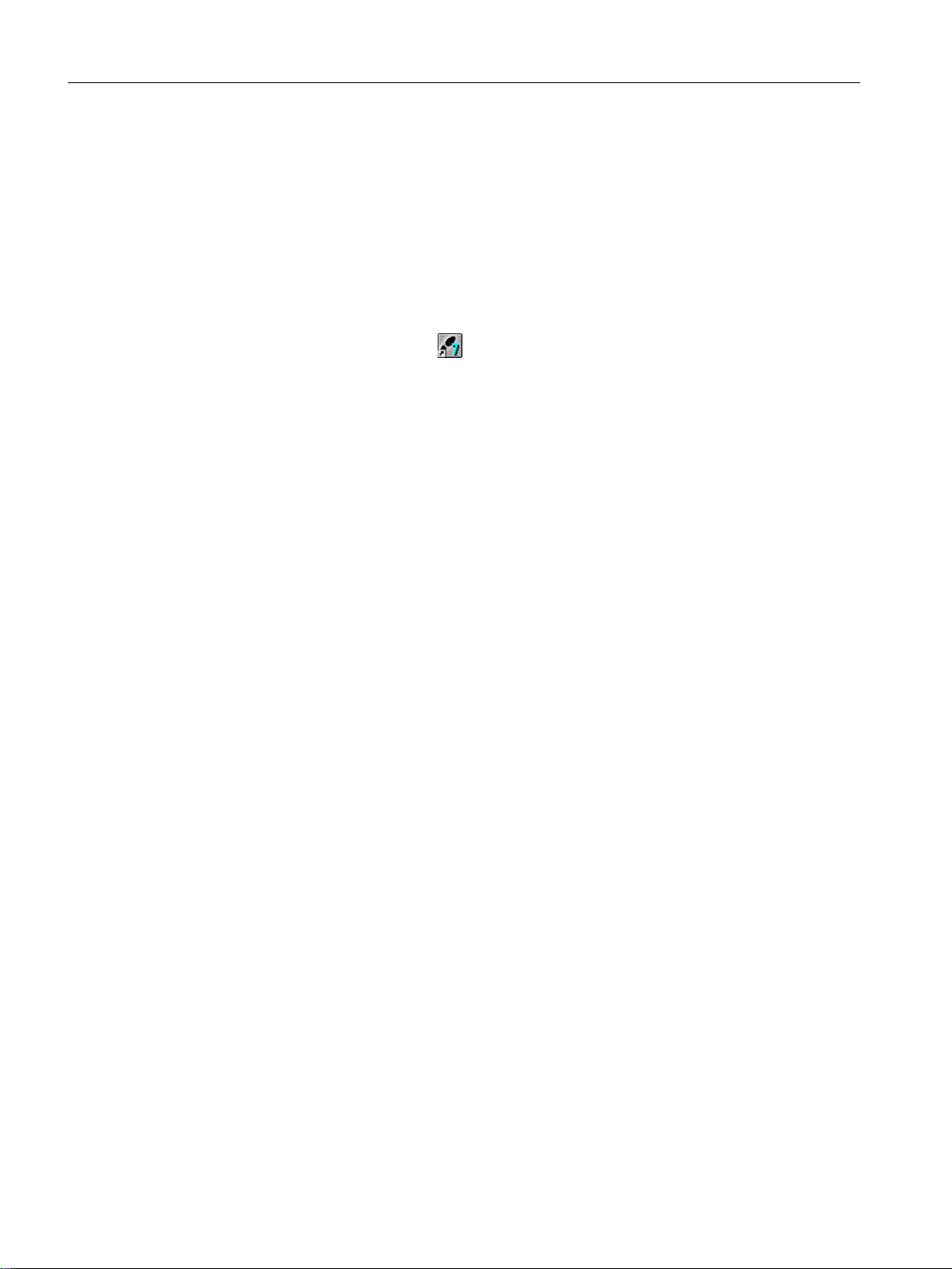
Piping and Instrumentation Diagram (P&ID)
5DZPDWHULDO
WDQN
5HDFWRU5HDFWRU
/,
1.
13
)&
1.
1.
1.
The piping and instrumentation diagram illustrates the precise sequence of the configuration
task and displays all the associated relevant process tags:
Initial work for the project
5.1 Planning the project
Explanation of the piping and instrumentation flow diagram
The terms used have the following meanings:
● LI111 (level indicator): measurement of the current fill level of the raw material tank.
● NK111 and NK112 (customer-specific identifier for valves): shut-off valves which must
always be opened for dosing raw materials.
● NP111 (customer-specific identifier for motors): pump that transports the raw material to
the reactors.
● NK113 or NK114 (customer-specific identifier for valves): valves, of which only one may
be open at a given time, in order to transport the raw material to either reactor 1 or reactor
2.
● FC111 (flow control) : actuator which regulates quantities for the raw material.
The states of the valves NK111 to NK114 can be displayed and monitored in the operator
station. You also have the possibility to influence the dosing via FC111.
PCS 7 SMART Getting Started - Part 1 (V9.0 with APL)
Getting Started, 12/2017, A5E42181435-AA 29
Page 30

'LUHFWFRQQHFWLRQXVLQJFURVVRYHUFDEOH
6LQJOHVWDWLRQV\VWHP
6,0$7,&6DXWRPDWLRQV\VWHP
(QJLQHHULQJVWDWLRQ(6RSHUDWRU
VWDWLRQ26
Initial work for the project
5.1 Planning the project
5.1.3 System configuration for the 'color_gs' project
Structure
The color_gs project will be implemented on a minimum system consisting of a single
automation system with a combined engineering station and operator station. The operator
station is designed as a single station system. The following figure illustrates the system
configuration.
Description
In Getting Started, you will build a control system which contains the following components:
● Automation system (AS):
The individual components are described in the section "Requirements for performing the
Getting Started".
● Program, which controls the "color_gs" plant:
You create this program in the ES and download it to the CPU. The CPU executes the
loaded program and displays the process values.
● Operator station (OS):
The plant operator controls and monitors the plant during runtime. You can create the
process picture seen by the plant operator on the OS.
Note
Plant configuration and hardware settings that result from it need to be especially adapted
to the requirements of this Getting Started.
When you configure a real project, you will use more automation systems and also operate
the engineering station and operator station(s) on several computers. In this case, the
hardware settings will be more complex. This will no longer correspond to the Getting
Started descriptions.
30 Getting Started, 12/2017, A5E42181435-AA
PCS 7 SMART Getting Started - Part 1 (V9.0 with APL)
Page 31

5.1.4 Configuration tasks overview
Configuration Sequence
You will configure the system components in the following configuration steps:
● Setting the Parameters for the Network (Page 32)
● Creating the Project (Page 34)
● Configuring the Stations (Page 41)
● Working in the Plant Hierarchy (Page 52)
● Creating CFC Charts (Page 61)
● Creating SFC Charts (Page 107)
● Compiling, Downloading, and Testing Charts (Page 129)
● Configuring operator stations (Page 141)
● Creating the Process Pictures (Page 153)
● Working in Process Mode (Page 171)
Initial work for the project
5.1 Planning the project
● Performing the Additional Task (Page 185)
PCS 7 SMART Getting Started - Part 1 (V9.0 with APL)
Getting Started, 12/2017, A5E42181435-AA 31
Page 32

Initial work for the project
5.2 Preparational settings for the network
5.2 Preparational settings for the network
5.2.1 Network and Interface settings
Settings
Before you configure the color_gs project, perform the following settings:
● Network adapter settings on the configuration console (Page 32)
PCS 7 SMART automatically identifies the network adapters installed on your computer
during startup. You can use this information to program the interfaces on the configuration
console.
Note
These settings are usually made immediately after PCS 7 SMART is installed. Verify the
settings and make necessary modifications if required.
● Selecting the network adapter
Select the network adapter used to communicate.
5.2.2 Procedure
5.2.2.1 Configuration console settings
Prerequisites
● All the necessary hardware components must be inserted on the rack and switched on.
● The crossover cable must be connected between the 3Com network adapter of your ES
computer and the Ethernet connection of the CPU.
Procedure
1. On the "Start" menu, Select Siemens Automation > SIMATIC > SIMATIC NET >
Communication Settings. The "Siemens Communication Settings" dialog box is displayed.
2. Open the "Modules" folder in the tree view.
3. Select the network adapter by which communication between the automation system and
the OS takes place.
4. Double-click the "General" entry in the detail view. The detail view for "General" is displayed.
5. In the detail view, select the "Configured mode" entry from the "Mode of the module" dropdown list.
6. Click "Apply". This button is only active if you have made changes. Your settings are now
saved. The network adapter is activated now.
PCS 7 SMART Getting Started - Part 1 (V9.0 with APL)
32 Getting Started, 12/2017, A5E42181435-AA
Page 33

Initial work for the project
5.2 Preparational settings for the network
7. Select the "Access points" folder in the tree view.
8. Double-click the "S7ONLINE" access point in the detail view. The detail view for "Access
point" is displayed.
9. In the "Associated interface parameter assignment" drop-down list, select "PC internal.local.
1". Click "Apply" to save your settings.
10.Specify "PG mode" as the "Mode of the module" for all other network adapters.
11.Close the configuration console.
PCS 7 SMART Getting Started - Part 1 (V9.0 with APL)
Getting Started, 12/2017, A5E42181435-AA 33
Page 34

Initial work for the project
5.3 Creating the project
5.3 Creating the project
5.3.1 "New Project" Wizard usage
PCS 7 "New Project" Wizard
The PCS 7 New Project wizard starts automatically when you open SIMATIC Manager using
default settings. You can enable or disable this option in the PCS 7 New Project wizard.
The New Project wizard guides you in creating a new project and offers default settings. The
PCS 7 wizard automatically creates various objects according to the default settings or user
defined settings.
color_gs objects
The following objects are essential for the color_gs project:
● Hardware objects: SIMATIC stations, for example a SIMATIC 400 station for the AS, a
SIMATIC PC station for the OS.
● Hierarchy folders representing the hierarchy levels of the plant structure. The number of
hierarchy folders created corresponds to the setting you enter in the PCS 7 wizard.
● A CFC chart
● An SFC chart
● One picture per plant hierarchy folder
● A master data library
5.3.2 Background knowledge for the PCS 7 Wizard
What happens in the background when a new project is created?
The next two sections provide you with some theoretical background knowledge for the
PCS 7 New Project wizard. Two objects that are of great importance for working with PCS 7
SMART are:
● Multiproject
● Master data library
How does a multiproject function?
When you create a new project with the PCS 7 wizard, a multiproject is created automatically.
A multiproject consists of a number of single projects.
In the context of the color_gs project, the multiproject is structured as follows: The multiproject
represents the entire plant and all of the single projects within this multiproject based on the
PCS 7 SMART Getting Started - Part 1 (V9.0 with APL)
34 Getting Started, 12/2017, A5E42181435-AA
Page 35

Initial work for the project
5.3 Creating the project
individual phases of the process for producing paint. Since you are configuring only one phase
of the overall plant in this Getting Started, your multiproject contains only a single project.
Multiprojects give you an advantage to distribute single projects to different configuration
engineers who can then edit them. Once the configuration of the single projects is complete,
they can be merged to form a complete project.
In Getting Started, although you will be working within a multiproject, you will not be using the
wide range of functions provided by this multiproject engineering.
Detailed information is available in the
Manual.
What is a master data library?
When you create a new project with the PCS 7 wizard, a master data library is created
automatically. You store all the blocks required for the entire project in this library. Before you
create a CFC, for example, you first store all the standard blocks you will insert in this CFC in
your master data library.
A master data library provides the following advantages:
● When you archive a project, the master data library is automatically archived along with it.
● You can also adapt the blocks and use copies (instances) of these adapted blocks
repeatedly in the project.
In the context of a multiproject, the master data library is important because it allows you to
provide all the project engineers who are involved with blocks of a defined version so that you
can ensure that only this version is used in the project.
Process Control System PCS 7; Engineering System
PCS 7 SMART Getting Started - Part 1 (V9.0 with APL)
Getting Started, 12/2017, A5E42181435-AA 35
Page 36

Initial work for the project
5.3 Creating the project
5.3.3 Procedure
5.3.3.1 Creating the color_gs Project
Procedure
The PCS 7 Wizard assists you in creating the "color_gs" project. To create the "color_gs"
project:
1. Open SIMATIC Manager.
2. Select File > 'New Project' Wizard.
The "PCS 7 Wizard: 'New Project'" is displayed.
3. In step 2(4) "Which CPU are you using in your project?", in the "CPU" drop-down list, select
the required CPU.
All available automation systems of the selected CPU type is listed with MLFB numbers
and brief descriptions.
PCS 7 SMART Getting Started - Part 1 (V9.0 with APL)
36 Getting Started, 12/2017, A5E42181435-AA
Page 37

Initial work for the project
5.3 Creating the project
4. In the "Bundle" section, select the required "MLFB" entry, and then click "Next".
5. In Step 3(4) "Which objects are you still using?", perform the following settings:
– Select "4" from the "Number of levels" drop-down list.
– Under "AS objects", verify that the "CFC" and "SFC" check boxes are selected.
– Select the "PCS 7 OS" check box under "OS objects". The "Single station system" option
is automatically selected.
6. Click "Next".
7. In Step 4(4), enter the name "color_gs_prj" in the "Directory name" box and accept the
default storage location.
PCS 7 SMART Getting Started - Part 1 (V9.0 with APL)
Getting Started, 12/2017, A5E42181435-AA 37
Page 38

Initial work for the project
5.3 Creating the project
8. Click "Preview >>>" to see a preview of your current configuration status.
This preview corresponds to the appearance of the project in SIMATIC Manager.
9. Click "Finish".
Note
● When you start SIMATIC Manager, the previously opened project is displayed, to close the
previous project and to open the "color_gs_prj" project, follow the instructions provided in
the section "How to close and open the "color_gs" project (Page 39)".
● To activate different views, follow the instructions provided in the section "How to work with
the various views (Page 39)".
PCS 7 SMART Getting Started - Part 1 (V9.0 with APL)
38 Getting Started, 12/2017, A5E42181435-AA
Page 39

Result
The project is displayed in the plant view of the SIMATIC Manager as follows:
5.3.3.2 Opening and Closing the "color_gs" Project
Procedure for Closing a Project
1. If you have other projects open in SIMATIC Manager, close these projects.
Initial work for the project
5.3 Creating the project
2. Select Window > [Name of project] and select the project you want to close.
SIMATIC Manager displays the project in the foreground.
3. Select File > Close. The project is closed.
Procedure for Opening a Project
1. Open SIMATIC Manager.
2. If your project "color_gs" does not open automatically, select File > Open. The "Open
Project" dialog box is displayed.
3. Select the "Multiprojects" tab and select "color_gs_prj_MP".
4. Click "OK". The project with the associated master data library is displayed.
5.3.3.3 How to Work in the Various Views
Introduction
Once you have opened your project in SIMATIC Manager, you can display the project in various
views and switch between these views.
Procedure
Select View > [Name of the desired view] in SIMATIC Manager:
● Component view
● Plant view
● Process object view
PCS 7 SMART Getting Started - Part 1 (V9.0 with APL)
Getting Started, 12/2017, A5E42181435-AA 39
Page 40

Initial work for the project
5.3 Creating the project
or
Select Window > [Name of the project (name of the view)] if you have already opened several
projects.
PCS 7 SMART Getting Started - Part 1 (V9.0 with APL)
40 Getting Started, 12/2017, A5E42181435-AA
Page 41

5.4 Configuring the stations
5.4.1 Configuration overview
Overview
Configure the control system components which the PCS 7 wizard: 'New Project' has
automatically inserted. This includes components such as the AS, the OS, and the associated
connections.
For this purpose you must perform the following configuration steps:
Step Action
1 Configure AS (Page 42)
2 Rename PC station (Page 44)
3 Configure OS (Page 45)
4 Set connection in NetPro (Page 47)
5 Download hardware configuration (Page 50)
Initial work for the project
5.4 Configuring the stations
Local PC station
The plant configuration for this Getting Started is a single station system; the ES and OS are
on one computer. In this way, the local PC station you configure represents the ES and the
OS at the same time.
PCS 7 SMART Getting Started - Part 1 (V9.0 with APL)
Getting Started, 12/2017, A5E42181435-AA 41
Page 42
Initial work for the project
5.4 Configuring the stations
5.4.2 Procedure
5.4.2.1 AS configuration
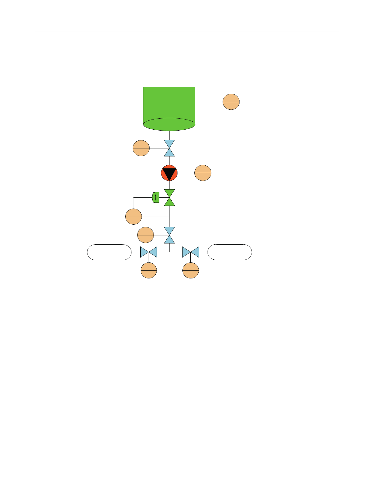
Procedure
1. In SIMATIC Manger, in "Component View", select "color_gs_prj_MP\color_gs_prj_Prj
\SIMATIC 400(1)" folder in the tree view.
2. Select "Hardware" object in the detail view. Click Edit > Open Object.
HW Config opens and the hardware structure of your plant is displayed.
Note
Select View > Catalog if the hardware catalog is not displayed.
The hardware catalog opens and the "PCS7_Vxx_SMART" profile is enabled.
3. Select the X5 slot (PN-IO-X5 module) and then select the menu command Edit > Object
Properties.
The "Properties - PN-IO-X5(R0/S2.5)" dialog box is displayed.
PCS 7 SMART Getting Started - Part 1 (V9.0 with APL)
42 Getting Started, 12/2017, A5E42181435-AA
Page 43
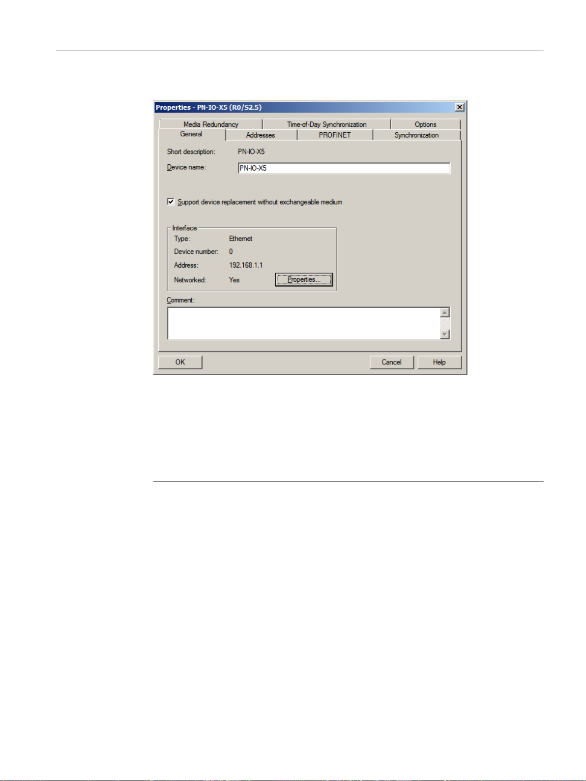
4. In the "General" tab, in the "Interface" group, click "Properties".
Initial work for the project
5.4 Configuring the stations
The "Properties - Ethernet interface PN-IO-X5(R0/S2.5)" dialog box is displayed.
5. In the "IP address" box, enter an available IP address within the address range of your
computer.
Note
To find an appropriate IP address, in SIMATIC Manager, use the PLC > Edit Ethernet
Node option.
6. In the "Subnet mask" box, enter the correct subnet mask for your computer.
7. Click "New" to create a new network connection. The CPU uses this network connection
to communicate with the ES.
The "Properties - New subnet Industrial Ethernet" dialog box is displayed.
PCS 7 SMART Getting Started - Part 1 (V9.0 with APL)
Getting Started, 12/2017, A5E42181435-AA 43
Page 44

Initial work for the project
5.4 Configuring the stations
8. Click "OK" to apply all the default settings.
The "Ethernet(1)" entry is entered in the "Subnet" list and is already selected.
9. Click "OK".
Your settings are applied and the dialog box closes.
10.Click "OK".
Your settings are applied and the dialog box closes.
11.Select Station > Save and Compile.
12.Close HW Config.
5.4.2.2 Renaming the PC Station
Prerequisites
● The color_gs project is open in SIMATIC Manager.
● The component view is activated.
Procedure
1. Select the "color_gs_prj_MP\color_gs_prj_Prj\SIMATIC PC Station(1)" object in the tree
view.
2. Click Edit > Object Properties. The "Properties - SIMATIC PC Station" dialog box is
displayed.
PCS 7 SMART Getting Started - Part 1 (V9.0 with APL)
44 Getting Started, 12/2017, A5E42181435-AA
Page 45

Initial work for the project
5.4 Configuring the stations
3. In the "Name" input box, enter the name of the local computer as it is displayed in the
network.
Note
To find the computer name, select Control Panel > System and view the "Computer name,
domain, and workgroup settings" section.
4. In the "Computer name" area, select the "Computer name identical to PC station name"
check box.
The computer name is automatically entered in the "Computer name" field at the bottom of
the dialog box.
5. Click "OK".
Your settings are applied and the dialog box closes.
The component view identifies the PC station icon with a yellow arrow.
Note
If the PC station is not labeled with a yellow arrow, press F5 to refresh the screen.
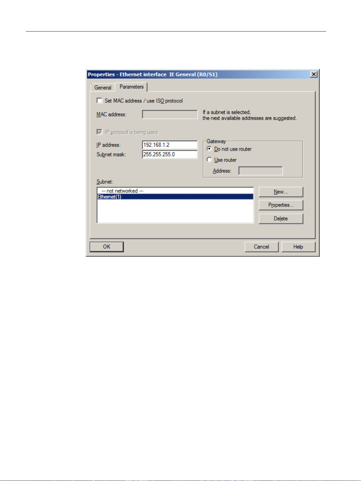
5.4.2.3 Configuring the PC station of the OS
Prerequisites
● The color_gs project is open in SIMATIC Manager.
● The component view is activated.
Procedure
1. Select the "color_gs_prj_MP\color_gs_prj_Prj\[name of the PC station]" folder in the tree
view.
2. Select the "Configuration" object in the detail view, and select Edit > Open Object.
HW Config opens and the OS components are displayed.
HW Config opens with the settings you made when configuring the AS:
– The hardware catalog is open.
– The "PCS7_Vxx" profile is active.
3. Select the following CP from the hardware catalog: "SIMATIC PC Station\CP Industrial
Ethernet\IE General/SW Vxx..." and move it to slot 1 using drag-and-drop.
The "Properties - Ethernet Interface IE General (R0/S1)" dialog box is displayed.
4. Verify that the "Set MAC address/use ISO protocol" check box is not selected.
5. Verify that the "IP protocol is being used" check box is selected.
6. In the "IP address" box, enter the IP address of your computer.
PCS 7 SMART Getting Started - Part 1 (V9.0 with APL)
Getting Started, 12/2017, A5E42181435-AA 45
Page 46
Initial work for the project
5.4 Configuring the stations
7. Select "Ethernet(1)" from the "Subnet" list.
This is the connection that you have already configured for the CPU.
PCS 7 SMART Getting Started - Part 1 (V9.0 with APL)
46 Getting Started, 12/2017, A5E42181435-AA
Page 47
8. Click "OK" to apply your settings.
The dialog box closes and the HW Config window is displayed.
Initial work for the project
5.4 Configuring the stations
9. Select Station > Save and Compile.
10.Close HW Config.
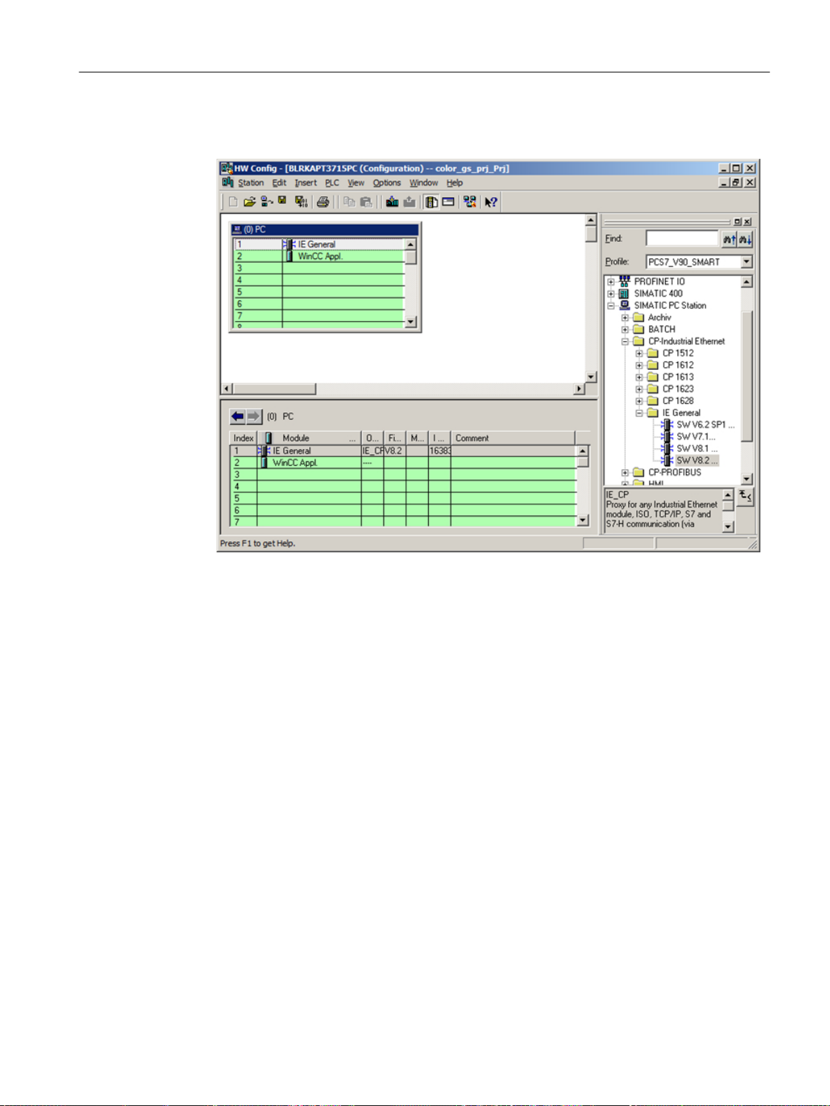
5.4.2.4 NetPro settings
Prerequisites
● The color_gs project is open in SIMATIC Manager.
● The component view is activated.
Procedure
1. Select the "color_gs_prj_MP\color_gs_prj_Prj\[name of the local computer]\WinCC Appl."
object in the tree view.
2. Select "Connections" in the detail view. Now, select Edit > Open Object.
NetPro opens.
3. Select the "WinCC Appl." object for the SIMATIC PC station.
4. Select the first line in the detail view at the bottom. Now, select Insert > New Connection.
The "Insert New Connection" dialog box opens.
PCS 7 SMART Getting Started - Part 1 (V9.0 with APL)
Getting Started, 12/2017, A5E42181435-AA 47
Page 48

Initial work for the project
5.4 Configuring the stations
5. Select your project's CPU in the tree view.
This CPU is the communication partner of the OS, which means that the OS receives the
data of this automation system.
6. In the "Connection" group, ensure that "S7 connection" type is set and the "Display
properties before inserting" check box is selected.
7. Click "OK".
The "Properties - S7 connection" dialog box opens with the "General" tab activated.
PCS 7 SMART Getting Started - Part 1 (V9.0 with APL)
48 Getting Started, 12/2017, A5E42181435-AA
Page 49

Initial work for the project
5.4 Configuring the stations
8. Select the following connection partners for the connection between the CPU and OS:
– Local: Interface "[Network adapter of the OS]", e.g., IE General
– Partner: Interface "[CP of the AS]", e.g., CPU 410 SMART
9. Click "OK".
The new connection is shown in the list. This connection is also displayed if you select the
CPU for the AS.
10.Select Network > Save and Compile.
The "Save and Compile" dialog box opens.
11.Activate the "Compile and check everything" option button and click "OK".
When the compilation operation is completed, the "Outputs for consistency check" window
opens.
12.If the compilation was executed without errors, close the window. If any errors are displayed,
correct them based on the information in the error messages and repeat the compilation
operation.
13.Close NetPro.
5.4.2.5 Configuring and downloading the PC station of the OS
Procedure
1. In SIMATIC Manager, select the PC station, and then select PLC > Configure.
The "Configure" dialog box is displayed.
2. Click "Configure".
The dialog box "Configure: <Selected PC Station>" is displayed.
PCS 7 SMART Getting Started - Part 1 (V9.0 with APL)
Getting Started, 12/2017, A5E42181435-AA 49
Page 50

Initial work for the project
5.4 Configuring the stations
3. To perform and complete remote configuration, follow the instructions in the online help of
the "Configure: <Selected PC Station>" dialog box.
4. Click "OK" and acknowledge the subsequent information windows by clicking "OK".
The configuration data is transferred to the PC station.
5. When the "Transfer completed successfully" message is displayed, click "Close" on the
"Configure" dialog box. You must still download the network settings to this PC station in
order to activate the network connections.
6. Select the PC station, and select PLC > Download.
The "Download" dialog box is displayed.
7. Click "Yes".
The "Stop Target Modules" dialog box is displayed.
8. Click "OK".
The download is complete.
5.4.2.6 Downloading the hardware configuration of the AS
Introduction
Prerequisites
Procedure
This section describes how to download the hardware configuration for the AS. After you have
configured and set the hardware, this information must be available to the CPU. Therefore,
download the hardware configuration to the CPU.
● The CPU is in "STOP" mode.
● The color_gs project is open in SIMATIC Manager.
● The component view is activated.
1. Select the "color_gs_prj_MP\color_gs_prj_Prj\SIMATIC 400(1)" folder in the tree view.
2. Select PLC > Compile and Download Objects.
The "Compile and Download Objects" dialog box opens.
3. Select the check boxes in the "Compile" and "Download" columns of the "color_gs\SIMATIC
400(1)\Hardware" object.
4. Click "Start".
"Downloading program changes during operation can, in the case of malfunctions or
program errors, cause serious damage to personnel and equipment! Make sure..."
message pops up.
5. Click "OK".
The compile and download operation starts. The log file is opened in the text editor when
the function is complete.
6. Close the text editor.
PCS 7 SMART Getting Started - Part 1 (V9.0 with APL)
50 Getting Started, 12/2017, A5E42181435-AA
Page 51

5.4 Configuring the stations
7. Click "Close" in the "Compile and Download Objects" dialog box.
The dialog box closes.
8. Start the CPU.
Initial work for the project
PCS 7 SMART Getting Started - Part 1 (V9.0 with APL)
Getting Started, 12/2017, A5E42181435-AA 51
Page 52

Initial work for the project
5.5 Working in the plant hierarchy
5.5 Working in the plant hierarchy
5.5.1 Introduction to plant hierarchy
Plant hierarchy
The plant hierarchy (PH) maps the hierarchical structure of your plant. For example, a plant,
unit or function. PH provides you with many settings. The most important ones are:
● Number of hierarchy levels:
The nesting depth of these levels is determined by the plant structure. Rule: If your plant
structure is complex, you will require higher number of hierarchy levels to reflect it. With
PCS 7 wizard, hierarchy folders with default names are created according to your
specification.
● Determination of the hierarchy level(s) which influence the name of plant ID (HID):
The PCS 7 SMART project contains many instances of the HID. Messages generated in
the active process and tag names contain this HID in order to allow operators to quickly
recognize a specific plant unit associated with a message or tag. Rule: If your individual
HID part is longer and if you define more hierarchy levels, the entire HID becomes less
recoginizable.
● Deriving the picture hierarchy from the PH:
The process pictures are grouped in a specific hierarchy. This allows you to change from
an overview picture to a lower level picture in process mode. The subordinate pictures
represent a portion of the overview picture that is very accurate. The hierarchy of the
process pictures corresponds with how they are stored in the plant hierarchy.
5.5.2 Plant hierarchy settings
Prerequisites
● The color_gs project is open in SIMATIC Manager.
● The plant view is activated.
Procedure
1. Select the "color_gs_prj_MP\color_gs_prj_Prj" hierarchy level in the tree view.
2. Select Options > Plant Hierarchy > Settings
The "Customize Plant Hierarchy" dialog box opens where you can set the plant hierarchy
options.
3. Enter the value "4" in the "Number of hierarchy levels" field.
This setting allows up to four hierarchy levels to be defined.
4. Enter the value "10" in the "Max. number of characters" boxes for all four hierarchy levels.
This setting limits the length of the HID string to 10 characters per hierarchy level.
PCS 7 SMART Getting Started - Part 1 (V9.0 with APL)
52 Getting Started, 12/2017, A5E42181435-AA
Page 53

Initial work for the project
5.5 Working in the plant hierarchy
5. Select the "Included in HID" check boxes for levels 1 to 4.
6. Select the "OS area" option for level 2.
7. Select the "Derive picture hierarchy from the plant hierarchy" check box.
The dialog box now appears as follows:
8. Click "OK" to apply your settings.
The "You have changed the "Included in HID" property. Do you want the changes to be
applied to the already existing hierarchy folders?" message dialog is displayed.
9. Click "Yes".
This accepts all the settings.
PCS 7 SMART Getting Started - Part 1 (V9.0 with APL)
Getting Started, 12/2017, A5E42181435-AA 53
Page 54

Initial work for the project
5.5 Working in the plant hierarchy
5.5.3 Plant view structure
Plant hierarchy of the color_gs project
You have now specified four hierarchy levels with the PCS 7 Wizard 'New Project'. As a result,
you will find the following hierarchy folders in the tree view of your project:
● Process cell - level 1
● Unit - level 2
● Function - level 3
● Device - level 4
The names of the hierarchy folders are default names assigned automatically by PCS 7
SMART when the project is created.
For your "color_gs_prj_MP" project, you must adapt this structure to the individual requirements
of the "color_gs" project, change the default names, and insert new hierarchy folders. This
gives you a clear structure and makes it easier to navigate through your project. You can also
treat all the objects as individual units.
The following hierarchy folder names are specified in the Getting Started for the various
components of the plant:
Default name Hierarchy folder Technological assignment
Process cell Plant1 Complete plant
Unit RMT1 Raw materials tank 1
Function FC111 Flow control (dosing)
Function LI 111 Level indicator for raw material tank 1
Function NP 111 Pump control
Function NK 111 Valve control
Function NK 112 Valve control
Function NK 113 Valve control
Function NK 114 Valve control
Device ADDIT Support chart for checking the process values
5.5.4 Adapting default names
Prerequisites
● The color_gs project is open in SIMATIC Manager.
● The plant view is activated.
PCS 7 SMART Getting Started - Part 1 (V9.0 with APL)
54 Getting Started, 12/2017, A5E42181435-AA
Page 55

Procedure for renaming the "Plant" folder
1. Select the hierarchy folder "color_gs_prj_MP\color_gs_prj_Prj\Process cell(1)".
2. Select Edit > Object Properties.
The "Properties - Hierarchy Folder" dialog box opens with the "General" tab activated.
3. Enter "Plant1" in the "Name" input box.
Initial work for the project
5.5 Working in the plant hierarchy
4. Click "OK" to apply your settings.
The dialog box closes and the name of the hierarchy folder is changed to "Plant1".
Procedure for renaming the "Unit" folder
1. Select the hierarchy folder "Unit (1)".
2. Select Edit > Object Properties.
The "Properties - Hierarchy Folder" dialog box opens with the "General" tab activated.
3. Enter "RMT1" in the "Name" input box.
PCS 7 SMART Getting Started - Part 1 (V9.0 with APL)
Getting Started, 12/2017, A5E42181435-AA 55
Page 56

Initial work for the project
5.5 Working in the plant hierarchy
4. Switch to the "Control and Monitoring Attributes" tab.
The "No modification when renaming the hierarchy folder" check box is deactivated by
default. This ensures that the text for the OS area ID is always changed according to the
name of the hierarchy folder.
5. Click "OK" to apply your settings.
The dialog box closes and the name of the hierarchy folder is changed to "RMT1".
Procedure for renaming additional folders
1. Select the hierarchy folder "color_gs_prj_MP\color_gs_prj_Prj\Plant1\RMT1\Function(1)".
2. Select Edit > Object Properties.
The "Properties - Hierarchy Folder" dialog box opens.
3. Enter "FC111" in the "Name" input box.
4. Click "OK".
Your settings are applied and the dialog box closes.
5. Select "color_gs_prj_MP\color_gs_prj_Prj\Plant1\RMT1\FC111\Device(1)" folder.
6. Select Edit > Object Properties.
The "Properties - Hierarchy Folder" dialog box opens.
7. Enter "ADDIT" in the "Name" input box.
8. Click "OK".
Your settings are applied and the dialog box closes.
PCS 7 SMART Getting Started - Part 1 (V9.0 with APL)
56 Getting Started, 12/2017, A5E42181435-AA
Page 57

5.5.5 Inserting additional hierarchy folders
Prerequisites
● The color_gs project is open in SIMATIC Manager.
● The Plant View is activated.
Procedure
1. Select the "RMT1" folder.
2. Select Insert > Technological Objects > Hierarchy Folder.
The program generates a new hierarchy folder named "Function [consecutive number]".
3. Change name of the newly created folder to "LI111".
4. Press "Enter".
5. Repeat steps 1 to 4 to create additional hierarchy folders:
– NP111 – motor control
Initial work for the project
5.5 Working in the plant hierarchy
Result
– NK111 – valve control
– NK112 – valve control
– NK113 – valve control
– NK114 – valve control
Your plant hierarchy must now appear as follows:
PCS 7 SMART Getting Started - Part 1 (V9.0 with APL)
Getting Started, 12/2017, A5E42181435-AA 57
Page 58

Initial work for the project
5.5 Working in the plant hierarchy
5.5.6 Checking the assignment of AS/OS to the plant hierarchy
Hierarchy folders assignment
The individual components of the plant are assigned to specific automation systems and
specific operator stations. This information is provided to each hierarchy folder of the plant
hierarchy. This is only important if you have more than one automation system or operator
station in your project.
In the "color_gs" project, you have only one automation system and one operator station. As
a result, all the hierarchy folders are automatically assigned.
Procedure for checking the assignment
1. Select the "RMT1" hierarchy folder, and select Edit > Object Properties.
The "Properties - Hierarchy Folder" dialog box opens.
2. Select the "AS-OS Assignment" tab.
Here you will find the following assignment:
– In the "Assigned AS (chart folder)" list, you will see the automation system that
processes the data.
– In the "Assigned OS" list, you will see the operator station where data is displayed.
3. Click "OK" to close the dialog box.
PCS 7 SMART Getting Started - Part 1 (V9.0 with APL)
58 Getting Started, 12/2017, A5E42181435-AA
Page 59

5.6 Current status
5.6.1 Current state of your project
Completed Configuration Tasks
So far, you have made the following settings for your project:
● You have created the "color_gs" project in SIMATIC Manager.
● You have configured the hardware components in HW Config.
● You have downloaded the hardware configuration from HW Config to the CPU.
● You have configured and loaded the PC station of the OS.
● You have entered settings in the plant hierarchy.
● You have mapped the plant structure of the "color_gs" project in the plant hierarchy.
Initial work for the project
5.6 Current status
PCS 7 SMART Getting Started - Part 1 (V9.0 with APL)
Getting Started, 12/2017, A5E42181435-AA 59
Page 60

Initial work for the project
5.6 Current status
PCS 7 SMART Getting Started - Part 1 (V9.0 with APL)
60 Getting Started, 12/2017, A5E42181435-AA
Page 61

Creating CFCs
6.1 CFC Charts and the CFC Editor
Introduction
CFCs assist you in creating the entire proces of a plant by continuous sequences. You can
create them in the PCS 7 CFC Editor.
6
You can create CFCs by inserting blocks from the
include single blocks. For example, blocks for closed-loop control of a process or for monitoring
measured values. The inputs and outputs of these blocks are then interconnected and
assigned parameters directly in the CFC Editor. The user-friendly graphic user interface of the
CFC Editor assists you in this task.
PCS 7 SMART also provides process tag types in the standard library. They represent full
CFCs for various process tags such as motors and valves.
You can retrieve the CFCs in the plant hierarchy. To keep the project structure clear, CFCs
are always stored in the hierarchy folders according to their relevance in the process.
Identification of CFCs
CFCs are identified by the icon:
PCS 7 Library Vxx
into the CFCs. These
PCS 7 SMART Getting Started - Part 1 (V9.0 with APL)
Getting Started, 12/2017, A5E42181435-AA 61
Page 62

Creating CFCs
6.2 Working with libraries
6.2 Working with libraries
6.2.1 CFC Charts and the master data library
Introduction to the master data library
When creating CFC charts, you will be working with the master data library. Do not copy any
blocks and process tag types directly from the PCS 7 AP library to the CFC charts of your
project. Instead, create the blocks and process tags as required in the master data library and
copy these objects from this library to the CFC charts.
Advantages of the master data library
The advantages of using the master data library is:
● Ensures that the the same version of a block is used in a project without any confusion.
This is important if there is more than one project engineer working on a project with a
multiproject.
● Provides you with the convenience of hiding libraries. This function allows you to hide all
libraries except for the master data library, in order to prevent inconsistency and errors
within the project.
● They are archived automatically when you archive the multiproject.
6.2.2 Storing objects in the master data library
Changes to blocks
You can change the properties of the block in the master data library. For example, you can
adapt messages specifically to your project requirements. Each block instance that is created
when you insert a block in a CFC automatically has the modified properties.
This means that you only have to modify the block once in the master data library and not
repeatedly for each individual block instance.
Modifications to blocks intended for a specific CFC are made directly in the CFC block instance.
For example, parameters for inputs and outputs, such as setpoints and limit values.
Master data library and process tag types
You can also store the process tag types provided by PCS 7 SMART in your master data
library. All the blocks included in this process tag type are automatically entered in the block
folder of your master data library at the background.
PCS 7 SMART Getting Started - Part 1 (V9.0 with APL)
62 Getting Started, 12/2017, A5E42181435-AA
Page 63
Basic procedure
Step Action
1 Open library (Page 64)
2 Store all blocks in your master data library (Page 65)
The PCS 7 wizard automatically generates the master data library when you create a
project.
3 Store process tag types in the master data library (Page 67)
6.2.3 Working with the master data library
Creating a master data library for a large project requires detailed planning before the CFC
charts are actually created. In this Getting Started, we will provide you with all the blocks you
require for the "color_gs" project. These objects are listed in the table below.
Legend for the tables
Creating CFCs
6.2 Working with libraries
● Object name: This is an alphanumeric code for the block that is displayed in PCS 7 SMART.
● Symbolic name: Short descriptive name for the block.
● Meaning: Short description of the purpose of this block.
● Type of block: Defines the block category.
● Associated CFC: Returns all CFCs where the block is installed.
Master data library blocks
Store the required blocks in your master data library. You need the following blocks for the
"color_gs" project:
Object
name
FB1809 DoseL Dosing of materials (quantity and flow) Dosing block CFC_FC111
FB1823 Integral Generates the time integral of an input
FB1828 Lag Smoothing the input value (low-pass
FB1845 MonAnL Monitors an analog measured value Monitoring block CFC_LI111
FB1866 OpDi01 Manipulates a digital value Operator control
FB1869 Pcs7AnIn Processes an analog input value sig‐
FB1870 Pcs7AnOu Processes an analog output value sig‐
Symbolic
name
Meaning Type of
block
Mathematical
value
filter)
nal
nal
block
Mathematical
block
block
Channel block CFC_LI111
Channel block CFC_FC111
Associated
CFC
CFC_LI111
CFC_FC111
CFC_LI111
CFC_FC111
CFC_SETP
CFC_FC111
PCS 7 SMART Getting Started - Part 1 (V9.0 with APL)
Getting Started, 12/2017, A5E42181435-AA 63
Page 64

Creating CFCs
6.2 Working with libraries
Object
name
FB1874 PIDConL Continuous PID controller Controller block CFC_FC111
FC360 Mul04 Multiplies input values and returns the
Symbolic
name
Meaning Type of
result at the output
Process tag types in the master data library
Store the required process tag types in your master data library. You need the following process
tag types for the "color_gs" project:
Process tag type (CFC) Meaning Assigned CFC
Motor_Lean CFC for a motor CFC_NP111
Valve_Lean CFC for a valve CFC_NK111
6.2.4 Opening the libraries
Prerequisites
SIMATIC Manager is open.
block
Mathematical
block
Associated
CFC
CFC_FC111
CFC_LI111
Procedure
1. Select File > Open....
The "Open Project" dialog box opens.
2. Select "Libraries" tab.
PCS 7 SMART Getting Started - Part 1 (V9.0 with APL)
64 Getting Started, 12/2017, A5E42181435-AA
Page 65

6.2 Working with libraries
3. Select "PCS 7 AP Library Vxx" and "color_gs_prj_Lib" libraries in the list.
Creating CFCs
4. Click "OK".
Both libraries appear in the component view.
6.2.5 Storing blocks
Prerequisites
● SIMATIC Manager is open.
● The PCS 7 library "PCS 7 AP Library Vxx" is open and the component view is activated.
● The "color_gs_prj_Lib" master data library is open and the component view is activated.
Procedure
1. The PCS 7 AP Library Vxx (Component view) window is open by default, if not, select
Window > PCS 7 AP Library Vxx (Component view).
The PCS 7 AP library opens.
2. Select the "PCS 7 AP Library Vxx\Blocks + Templates\Blocks" item in the tree view.
The detailed view shows all the standard blocks provided by PCS 7 AP library Vx.x.
3. Select View > Details.
Both the object names (short names and symbolic names of the blocks) are displayed which
gives you more information.
PCS 7 SMART Getting Started - Part 1 (V9.0 with APL)
Getting Started, 12/2017, A5E42181435-AA 65
Page 66

Creating CFCs
6.2 Working with libraries
4. In the detailed view, select the required blocks according to the following list:
– FB1809 - DoseL
– FB1823 - Integral
– FB1828 - Lag
– FB1845 - MonAnL
– FB1866 - OpDi01
– FB1869 - Pcs7AnIn
– FB1870 - Pcs7AnOu
– FB1874 - PIDConL
– FC260 - ChkREAL
– FC360 - Mul04
5. Select Edit > Copy.
6. Select Window > color_gs_prj_Lib (Component view).
The master data library opens.
PCS 7 SMART Getting Started - Part 1 (V9.0 with APL)
66 Getting Started, 12/2017, A5E42181435-AA
Page 67

Creating CFCs
6.2 Working with libraries
7. Select "In <color_gs_prj_MP>\color_gs_prj_Lib\S7 program(1)\Blocks" in the tree view.
8. Select Edit > Paste.
The selected blocks are inserted.
6.2.6 Storing process tag types
Introduction
This section will guide you in storing process tag types. You can store process tag types in the
"Charts" directory of your master data library in the Component view. Later, you can copy your
master data library from the "Templates" directory to the "Process tag types" directory in the
Plant View.
Prerequisites
● SIMATIC Manager is open.
● The PCS 7 library "PCS 7 AP Library Vxx" is open and the Component view is activated.
● The "color_gs_prj_Lib" master data library is open and the Component view is activated.
Procedure
1. Select Window > PCS 7 AP Library Vxx (Component view). PCS 7 AP library opens in
Component view.
2. Select the "PCS 7 AP Library Vxx\Blocks + Templates\ Templates" folder in the tree view.
The detailed view shows all the chart templates available in the PCS 7 AP library.
PCS 7 SMART Getting Started - Part 1 (V9.0 with APL)
Getting Started, 12/2017, A5E42181435-AA 67
Page 68

Creating CFCs
6.2 Working with libraries
3. Select the following charts in the detail view:
– "Motor_Lean"
– "Valve_Lean"
4. Select Edit > Copy.
5. Select Window > color_gs_prj_Lib (Component view).
The master data library opens.
6. Select "<color_gs_prj_MP>\color_gs_prj_Lib\S7 program(1)\Charts" in the tree view.
7. Select Edit > Paste.
All the selected process tag types are inserted.
8. Close the "PCS 7 AP Library Vxx".
9. Open "color_gs_prj_lib" in Plant View.
10.Select "<color_gs_prj_MP>\color_gs_prj_Lib\ Process tag types" folder in the tree view.
11.Switch to the Component view.
12.Select the "<color_gs_prj_MP>\color_gs_prj_Lib\S7 Program(1)\Charts" folder in the tree
view.
13.Select the "Motor_Lean" and "Valve_Lean" charts in the detail view.
14.Select Edit > Cut.
15.Select the "<color_gs_prj_MP> \ color_gs_prj_Lib \ Process tag types" folder in the plant
view.
16.Select Edit > Paste.
Note
As soon as a process tag type is stored in the master data library, all the individual blocks
present in this process tag type are automatically stored in the "Blocks" folder.
If you select the "<color_gs_prj_MP>\color_gs_prj_Lib\ S7 program(1)\ Blocks" folder in the
tree view, you can see all the blocks you have inserted or that were automatically stored
there when process tag types were copied in the detail window .
6.2.7 Showing and hiding libraries
Introduction
You can hide unwanted libraries in SIMATIC Manager. Hence, working with the CFC Editor
catalog is more clear and less prone to errors. Since you have stored all the necessary blocks
and process tag types in your master data library, you can work exclusively with this master
data library when creating the "color_gs" project.
You can show libraries quickly if you need them again.
PCS 7 SMART Getting Started - Part 1 (V9.0 with APL)
68 Getting Started, 12/2017, A5E42181435-AA
Page 69

6.2.8 Process to hide and show libraries
Prerequisites
1. SIMATIC Manager is open.
2. All the required blocks and charts in your master data library.
Procedure for Hiding Libraries
1. Select File > Manage.
The "Manage" dialog box opens.
2. Select the "Libraries" tab.
3. Select all the libraries in the list excluding the following:
– Master data library "color_gs_Prj_Lib"
– PCS 7 library "PCS 7 AP Library Vxx"
– SFC Library (x3)
Creating CFCs
6.2 Working with libraries
– Standard library
4. Click "Hide".
All selected libraries are removed from the list.
5. Click "Close".
You have now hidden all the libraries that you do not want to use. They will no longer be
displayed in the CFC Editor catalog.
PCS 7 SMART Getting Started - Part 1 (V9.0 with APL)
Getting Started, 12/2017, A5E42181435-AA 69
Page 70

Creating CFCs
6.2 Working with libraries
Procedure for Showing Libraries
1. Select File > Manage.
The "Manage" dialog box opens.
2. Select the "Libraries" tab.
3. Click "Display".
The "Browse" dialog box opens.
4. Select the "...\SIEMENS\STEP7\S7LIBS\ [Name of the library] object in the tree view.
The library is displayed in the right pane.
5. Click "OK".
The dialog box closes and the selected library is displayed and selected in the list of libraries
in the "Manage" dialog box.
6. Repeat steps 3 to 5 if you wish to show other libraries again.
7. Click "Close". The dialog box closes.
PCS 7 SMART Getting Started - Part 1 (V9.0 with APL)
70 Getting Started, 12/2017, A5E42181435-AA
Page 71

6.3 Technological significance of the charts in the project
6.3 Technological significance of the charts in the project
6.3.1 Charts in "color_gs" project
CFC Charts in the color_gs Project
The following CFCs are required for the "color_gs" project:
● CFC_SETP: Specification of process values.
● CFC_FC111: Closed-loop control of dosing amount and dosing speed.
● CFC_LI111: Control and simulation of the liquid level.
● CFC_NP111: Motor control.
● CFC_NK111 to CFC_NK114: Valve control.
Each chart has a process related meaning. To fully understand the part of the plant you are
configuring in Getting Started, you should understand the process related meaning of the
individual CFCs. A brief description of each individual chart is given below.
Creating CFCs
Details about Creating CFC Charts
You will create the CFC_SETP, CFC_FC111 and CFC_LI111 charts. PCS 7 SMART makes
the CFC_NP111 and CFC_NK11x available to you as a complete CFC in the form of a process
tag type. This will give you the advantage of using process tag types, which is stored in your
master data library.
Note
In the "color_gs" project, the CFC names are assigned according to the associated hierarchy
folder name and the process tag name. As a result, unique identification is always possible.
6.3.2 Process-Related meaning of the "CFC_SETP" CFC chart
CFC_SETP
CFC_SETP is used to check the process value. In this case, the blocks mean the following :
● The PARA_DOS_RM1_QTY block is a substitute block. It sets the flow and should be
connected to DOSE and to CTRL_PID.
● The PARA_DOS_RM1_SEL block specifies the target reactor.
PCS 7 SMART Getting Started - Part 1 (V9.0 with APL)
Getting Started, 12/2017, A5E42181435-AA 71
Page 72

Creating CFCs
6.3 Technological significance of the charts in the project
6.3.3 Process-Related meaning of the "CFC_FC111" CFC chart
CFC_FC111
CFC_FC111 is used to control the dosing quantity and dosing speed. In this case, the blocks
mean the following:
● The "Pcs7AnIn" block provides the currently dosed volume at the "PV_Out" output and
transfers this measured value to the "PV (process value) input of the "DoseL" block.
● The "PIDConL" block delivers the manipulated variable of the flow.
● "DoseL" delivers the setpoint for the flow (manipulated value for the "PIDConL" block) and
checks the dosing quantity.
● The manipulated variable for the valve is sent to the "MV" output of the "PIDConL" block.
Then, it is fed to the "MV_Trk" input of the "PIDConL" block in the absence of manipulated
variable feedback from the process.
● The "Pcs7AnOu" block sends out the manipulated variable to the valve.
6.3.4 Process-Related meaning of the "CFC_LI111" CFC chart
CFC_LI111
CFC_LI111 is used for controlling and simulating the fill level. In this case, the blocks mean
the following:
● The Pcs7AnIn" block reads the fill level of the raw material tank and outputs the current
value at "PV_Out" output.
● The "PV_Out" output is interconnected with the "OutTrk" input of the "Integral" block.
● The "Out" output is interconnected with the "PV" input of the "MonAnL" block.
● The "Mul04" block is used to simulate the quantity which is taken from the reservoir at the
given point of time.
6.3.5 Process-Related meaning of the "CFC_NP111" CFC chart
CFC_NP111
CFC_NP111 is used for pump controlling. In this case, the blocks mean the following:
● The "Pcs7DiIn" block supplies the current state of the pump - on or off, at the "PV_Out"
output.
● This value is interconnected to the "MotL" input (feedback ON) of the "FbkRun" block where
it is evaluated.
PCS 7 SMART Getting Started - Part 1 (V9.0 with APL)
72 Getting Started, 12/2017, A5E42181435-AA
Page 73

6.3 Technological significance of the charts in the project
● The plant operator or an upstream controller controls the "MotL" block.
● The "Pcs7DiOu" block takes the control command from the "OosAct" output of the "MotL"
block and outputs this to the pump in the process.
6.3.6 Process-Related meaning of the "CFC_NK11x" CFC chart
CFC_NK11x
CFC_NK11x is used for valve control. The blocks mean the following in this case:
● The "Pcs7DiIn" block provides feedback on the status of the valve - open or closed, to the
"VlvL" block.
● The "VlvL" block switches the valve according to the external controller settings or operator
settings. The control command is passed on from the "OosAct" output via the "Pcs7DiOu"
output driver to the valve.
Creating CFCs
PCS 7 SMART Getting Started - Part 1 (V9.0 with APL)
Getting Started, 12/2017, A5E42181435-AA 73
Page 74

Creating CFCs
6.4 CFCs in the Plant Hierarchy
6.4 CFCs in the Plant Hierarchy
6.4.1 Working with CFC charts
Introduction
Once you have made the preparations for creating the CFC charts by filling your master data
library, you can start creating the CFC charts.
Basic procedure for creating CFC charts
Step Action
1 Create empty CFC charts in the plant hierarchy
2 Insert individual blocks in an empty CFC chart
3 Interconnect the inputs and outputs of blocks and assign parameters to them
CFC Charts in the Plant Hierarchy
The PCS 7 "New Project" wizard has already created a CFC chart in your plant hierarchy. This
is stored in the "ADDIT" folder. It does not yet contain any blocks. You have to insert them in
the CFC Editor.
In addition, you require other charts for the "color_gs" project , which you insert in the plant
hierarchy and then edit in the CFC Editor.
It is important that you assign brief descriptive names for all CFC charts of the "color_gs" project
to understand your project in a better way.
6.4.2 Procedure
6.4.2.1 Renaming CFC charts in the Plant Hierarchy
Prerequisites
● The color_gs project is open in SIMATIC Manager.
● Plant View is activated.
PCS 7 SMART Getting Started - Part 1 (V9.0 with APL)
74 Getting Started, 12/2017, A5E42181435-AA
Page 75
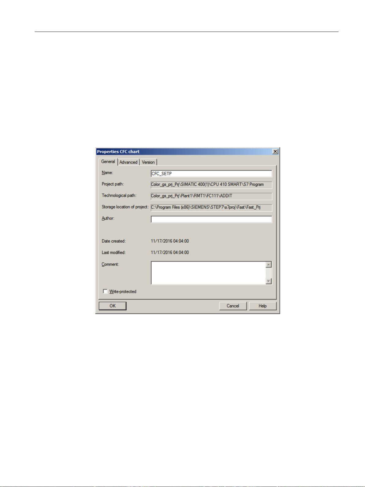
Procedure
Creating CFCs
6.4 CFCs in the Plant Hierarchy
To rename a CFC present in ADDIT folder:
1. Select the "color_gs_prj_MP\color_gs_prj_Prj\Plant1\RMT1\FC111\ADDIT" folder in the
tree view.
2. Select the "CFC(1)" object in the detail window.
3. Select Edit > Object Properties.
The "Properties CFC" dialog box opens with the "General" tab activated.
4. Enter "CFC_SETP" in the "Name" input box.
Chart names in real projects usually relate to a user-specified system for the identification
of process tags.
5. Click "OK" to apply your settings.
6.4.2.2 Inserting new CFC charts in the Plant Hierarchy
Inserting CFCs
Insert the following CFCs in the form of new, empty CFCs:
● "CFC_FC111"
● "CFC_LI111"
PCS 7 SMART Getting Started - Part 1 (V9.0 with APL)
Getting Started, 12/2017, A5E42181435-AA 75
Page 76

Creating CFCs
6.4 CFCs in the Plant Hierarchy
Prerequisites
● The color_gs project is open in SIMATIC Manager.
● Plant View is activated.
Procedure
1. Select the "color_gs_prj_MP\color_gs_prj_Prj\Plant1\RMT1\FC111" folder in the tree view.
2. Select Insert > Technological Objects > 2 CFC.
The CFC "CFC(1)" is inserted. When you insert new charts, PCS 7 first assigns the default
name "CFC" followed by a consecutive number and activates the input mode for a new
name.
3. Enter "CFC_FC111" and press "Enter".
4. Select the "color_gs_prj_MP\color_gs_prj_Prj\Plant1\RMT1\ LI111" folder in the tree view.
5. Select Insert > Technological Objects > 2 CFC. The CFC "CFC(1)" is inserted.
6. Enter "CFC_LI111" and press Enter.
6.4.2.3 Inserting the "Motor_Lean" process tag type
Introduction
You have already stored the "Motor_Lean" process tag type in your master data library. Now,
insert this process tag type into the plant hierarchy in your "color_gs" project.
Prerequisites
● The color_gs project is open in SIMATIC Manager.
● Plant View is activated.
Procedure
1. Select the "color_gs_prj_MP\color_gs_prj_Lib\Process tag types" item in the tree view.
The detail window displays the process tag types you have added to the master data library.
2. Select the "Motor_Lean" CFC, and select Edit > Copy.
3. Select the "color_gs_prj_MP\color_gs_prj_Prj\Plant1\RMT1\ NP111" folder in the tree view,
and select Edit > Paste. The "Motor_Lean" CFC chart is inserted in the hierarchy folder and
selected.
4. Select Edit > Object Properties.
The "Properties CFC" dialog box opens.
5. Change the default name "Motor_Lean" to "CFC_NP111" in the "Name" input box.
6. Click "OK" to apply your settings.
PCS 7 SMART Getting Started - Part 1 (V9.0 with APL)
76 Getting Started, 12/2017, A5E42181435-AA
Page 77

6.5 The current status...
6.5.1 Current status of your project
Completed Configuration Tasks
After creating CFCs, the following tasks are complete:
● You have stored all the necessary blocks and process tag types in the master data library.
● You have hidden unwanted libraries for the "color_gs" project so that only the
"color_gs_prj_Lib" master data library is visible.
● You have renamed and inserted new CFCs in the plant hierarchy.
● You have inserted the "Motor_Lean" process tag type in the plant hierarchy.
Creating CFCs
6.5 The current status...
PCS 7 SMART Getting Started - Part 1 (V9.0 with APL)
Getting Started, 12/2017, A5E42181435-AA 77
Page 78

Creating CFCs
6.6 Working with the CFC Editor
6.6 Working with the CFC Editor
6.6.1 Introduction to the CFC Editor
CFC Editor
CFC Editor is used to edit CFCs, insert and assign parameters to blocks. When you double
click a CFC, CFC Editor opens. The editor always opens in the last worked view.
The CFC Editor is separated into the following display areas:
● CFC
When you open an empty CFC, you can insert blocks required to describe continuous
processes. Later, you can assign parameters and interconnect the blocks.
● Catalog with blocks, libraries and CFCs
PCS 7 SMART saves all your work in the CFC Editor.
Additional information
Detailed information about the CFC Editor is available in the CFC online help and in the
Control System PCS 7, CFC for SIMATIC S7
6.6.2 CFC Chart in the CFC Editor
CFC
Each CFC can consist of up to 26 chart partitions. A new CFC consists of only one chart
partition. Only one chart partition is necessary for the "color_gs" project. Each chart partition
consists of six sheets.
You can select between two different views using buttons in the toolbar:
● A single sheet:
● Overview with six sheets:
The status bar shows you the location of your sheet and chart partition.
Process
Manual.
Changing from the overview to a single sheet
Double-click the required sheet to change from the overview to the single view.
The single sheets in the overview are arranged in the displayed order:
PCS 7 SMART Getting Started - Part 1 (V9.0 with APL)
78 Getting Started, 12/2017, A5E42181435-AA
Page 79

Creating CFCs
6.6 Working with the CFC Editor
Additional information
Detailed information is available in the CFC online help and in the
PCS 7, CFC for SIMATIC S7
6.6.3 Catalog in the CFC Editor
Opening the catalog
To open the catalog in CFC Editor, select View > Catalog.
Organization of the catalog
The catalog contains four tabs namely:
● Blocks: Sorted according to block families. You can work with this tab in the "color_gs"
project in order to place the PARA_DOS_RM1_QTY block from the "Operate" directory in
the "CFC_SETP" chart.
● Charts: You can find all the charts you have created in the plant hierarchy. For example,
CFC_FC111, CFC_LI111. The CFC that is currently open and displayed in the CFC Editor
is labeled by a small open folder.
Process Control System
Manual.
● Libraries: Contains all PCS 7 SMART standard libraries and your master data library.
You have already executed the "hide" function to hide all libraries that are not required to
configure the system in the ""color_gs" project. This means that you can only see the
"color_gs_prj_Lib" library.
PCS 7 SMART Getting Started - Part 1 (V9.0 with APL)
Getting Started, 12/2017, A5E42181435-AA 79
● Unplaced blocks: You can find blocks that are not displayed in a CFC. Within the "color_gs"
project, this tab is not displayed since there are no "unplaced blocks" in your project.
Page 80

Creating CFCs
6.6 Working with the CFC Editor
Additional information
Detailed information is available in the CFC online help and in the
PCS 7, CFC for SIMATIC S7
Manual.
6.6.4 Configuration steps for CFC charts overview
Overview
To create CFC charts, complete the following steps in the same order given below:
Step What?
1 Open chart (Page 80)
2 Insert blocks
Options:
● Insert blocks in "CFC_SETP" (Page 81)
● Insert blocks in "CFC_FC111" (Page 84)
● Insert blocks in "CFC_LI111" (Page 88)
3 Assign parameters to blocks
● Rename blocks
● Specify input/output values
4 Interconnect blocks (Page 92)
Process Control System
The "Insert blocks" step is skipped for process tag types. Now, you only have to configure and
interconnect the process tag types.
Information from the online help for the block
Note
If you need additional information on the blocks, (for example, the functions of the individual
block inputs), select a block in the library or directly in the CFC chart and press "F1". The online
help for this block opens immediately.
6.6.5 Opening the "CFC_SETP" CFC chart
Introduction
Open CFCs in order to place blocks.
PCS 7 SMART Getting Started - Part 1 (V9.0 with APL)
80 Getting Started, 12/2017, A5E42181435-AA
Page 81

Prerequisites
● The color_gs project is open in SIMATIC Manager.
● The plant view is activated.
Procedure
1. Select the "color_gs_prj_MP\color_gs_prj_Prj\Plant1\RMT1\ FC111\ ADDIT" folder in the
tree view.
2. Select the "CFC_SETP" object in the detail window and then select Edit > Open Object.
The CFC editor opens and you can now edit the open chart.
6.6.6 Assignment of block parameters in CFC charts
Assignment of Block Parameters
Each block has a number of different I/Os that are displayed in the properties dialog box table.
Click the column heading of the table to quickly find the inputs/outputs in this dialog box. The
column is then sorted in ascending or descending order.
Creating CFCs
6.6 Working with the CFC Editor
The I/Os of a block can be visible or invisible. You can only see invisible parameters in the
properties of the block but not in the CFC chart representation. In the properties of the block,
you can specify which I/Os in the CFC chart will be visible and invisible. In the "Not Displayed"
column, you need to deactivate the check box of the relevant I/O to make the I/O visible in the
CFC chart. This function makes it easy to read a CFC chart. In the "color_gs" project, you will
accept the default settings.
6.6.7 Inserting the blocks into the "CFC_SETP"
Prerequisites
● The "CFC_SETP" CFC chart is open in the CFC Editor -
Storage in the "color_gs_prj_MP\color_gs_prj_Prj\Plant1\RMT1\ FC111\ ADDIT" folder.
● The catalog is open.
Procedure
1. Select the "Libraries" tab in the catalog.
This is where the "color_gs_prj_Lib" library is displayed.
2. Open the "color_gs_prj_Lib\S7 program(1)\Blocks\Operate" folder in the tree view.
PCS 7 SMART Getting Started - Part 1 (V9.0 with APL)
Getting Started, 12/2017, A5E42181435-AA 81
Page 82

Creating CFCs
6.6 Working with the CFC Editor
3. Drag and drop the "OpDi01 - FB1866" block to the CFC. It is used to select the reactor
where the raw material is pumped.
4. Close the chart.
Note
If a block is displayed in pink color after you have inserted it and if no block I/Os are
displayed, it is covering an underlying block or extends beyond the edge of the sheet. In
this case, you must move the block with the mouse so that it does not cover any other block
and is within the sheet limits.
6.6.8 Assigning parameters for the blocks in "CFC_SETP"
Prerequisites
● The "CFC_SETP" CFC is open in the CFC Editor and is saved in the "color_gs_prj_MP\
color_gs_prj_Prj\Plant1\RMT1\FC111\ADDIT" folder.
● All blocks are inserted.
PCS 7 SMART Getting Started - Part 1 (V9.0 with APL)
82 Getting Started, 12/2017, A5E42181435-AA
Page 83

Procedure
Creating CFCs
6.6 Working with the CFC Editor
1. Select the "OpDi01" block and then select Edit > Object Properties.
The "Properties - Block" dialog box opens with the "General" tab activated.
2. Enter "PARA_DOS_RM1_SEL" in the "Name" input box.
The "OCM possible" check box is selected by default.
3. Switch to the "I/Os" tab.
Here you can assign parameters for all the I/Os of a block. The names of all inputs and
outputs are found in the "Name" column.
4. Position the cursor in the "Value" column of the "Out.Value" I/O and enter "0".
PCS 7 SMART Getting Started - Part 1 (V9.0 with APL)
Getting Started, 12/2017, A5E42181435-AA 83
Page 84

Creating CFCs
6.6 Working with the CFC Editor
5. Click "OK" to apply the settings.
"PARA_DOS_RM1_SEL" name is displayed in the CFC block header. When you create the
process pictures, you will interconnect the I/Os of the blocks from the CFCs with objects in
the process pictures. The tag name is formed from the plant hierarchy, the CFC name, and
the block name. You will find the "PARA_DOS_RM1_SEL" name again as part of the tag
name.
The values of the inputs/outputs are applied.
Block Block name in the project I/O Meaning Value Unit
OpDi01 PARA_DOS_RM1_SEL Out.Value* The output of the proc‐
* Invisible in CFC.
6. Close the CFC.
Do not create unnecessary block icons
In the "Properties - Block" dialog box of the the "General" tab, "Create block icons" determines
whether a block icon is created for use in WinCC. Do not set the check mark for blocks with
inputs and outputs that cannot be configured.
0
ess value is verified.
6.6.9 Inserting the blocks into the "CFC_FC111"
Prerequisites
● The "CFC_FC111" CFC is open in the CFC Editor and is saved in the "color_gs_prj_MP
\color_gs_prj_Prj\Plant1\RMT1\ FC111\" folder.
● The catalog is open, and the "Libraries" tab is visible.
● The "color_gs_prj_Lib\S7 program(1)\Blocks" folder is open in the tree view.
PCS 7 SMART Getting Started - Part 1 (V9.0 with APL)
84 Getting Started, 12/2017, A5E42181435-AA
Page 85

Procedure
Creating CFCs
6.6 Working with the CFC Editor
1. Drag and drop the following blocks:
– "Channel" folder: Pcs7AnIn - FB1869: Signal processing of an analog input value.
– "Dosage" folder: DoseL - FB1809: Dosing of raw material.
– "Math" folder: Mul04 - FC360: Multiplies input values and returns the result at the output.
– "Control" folder: PIDConL - FB1874 : Fill level monitoring and visualization of the level
in the process mode.
– "Channel" folder: Pcs7AnOu - FB1870: Processes an analog output value signal.
– Folder "Operate": OpDi01 - FB1866: Manipulating a digital value.
2. Arrange the blocks in the CFC as shown below:
3. Close the chart.
6.6.10 Assigning parameters for the blocks in the "CFC_FC111"
Prerequisites
● The "CFC_FC111" CFC is open in the CFC Editor -
Save in folder: "color_gs_prj_MP\color_gs_prj_Prj\Plant1\RMT1\ FC111\".
● All blocks are inserted.
PCS 7 SMART Getting Started - Part 1 (V9.0 with APL)
Getting Started, 12/2017, A5E42181435-AA 85
Page 86

Creating CFCs
6.6 Working with the CFC Editor
Procedure
1. For every block listed, open the "General" tab and the "I\Os" tab in the "Object Properties"
dialog box.
2. Enter the parameters for all blocks according to the table below.
Block Block name in
the project
Pcs7AnIn INPUT_U Mode Value status and measur‐
PV_In Process value (raw value) 16#0203
PV_InUnit Unit of measure for process
SimOn.Value 1 = Simulation on 1
SubsPV_In Substitute value 15.0
DoseL DOSE CR_A_DC Creep flow: Delay time for
CR_AH_Lim Creep flow: Limit high alarm 5.0
CR_Hyst Creep flow: Hysteresis for
DQ_AH_Tol Overdosage: Limit high
DQ_ExHiAct.Value Default for the internal\ex‐
DQ_Ext.Value Dosing quantity: External
DQ_HiLim.Value Limit dosing quantity 500.0
DQ_Int End value dosing quantity 20.0
DQ_OpScale.High Dosing quantity: High scale
DQ_Unit Unit of dosing in m³ 1034
DQ2_ExHiAct.Value Dosing quantity: 1 = High
DQ2_Ext.Value External fine dosing quanti‐
DQ2_HiLim.Value Fine dosing: Limit high set‐
DQ2_Int Fine dosing quantity 11.0
Feature.Bit16 1
Feature.Bit4 Set switch or button mode 1
Feature.Bit6 Reset dosing quantity when
PV_AH_Lim High display limit of the
PV_OpScale.High Process value: High scale
I/O Meaning Value
16#00000203
ing type
1348
value
5.0
incoming alarms [s]
0.2
alarm limit
3.0
alarm
1
ternal switchover
111.0
setpoint
550.0
limit of bar graph
1
limit for external setpoint
factor for fine dosing has
been reached
15.0
ty
350.0
point
1
dosing starts
700.0
process value for the dos‐
ing volume
350.0
limit of bar graph
PCS 7 SMART Getting Started - Part 1 (V9.0 with APL)
86 Getting Started, 12/2017, A5E42181435-AA
Page 87

Creating CFCs
6.6 Working with the CFC Editor
Block Block name in
the project
SP.Value Active flow setpoint 70.0
SP_Ext.Value External manipulated value 120.0
SP_ExtAct.Value Active external setpoint 1
SP_HiLim.Value Coarse dosing: High limit
SP_Int Coarse dosing setpoint 70.0
SP_LiOp.Value 1=Linking, 0=Operator Ac‐
SP_TrkExt 1 = Bumpless switchover
SP2_Ext.Value Fine dosing external set‐
SP2_HiLim.Value Fine dosing: High limit set‐
SP2_Int Fine dosing setpoint 9.0
TI.Value Reset time 30.0
Mul04 MUL In2.Value Value to be multiplied 1
In3.Value The value to be multiplied
PIDConL CTRL_PID AutModLi.Value Interconnection to automat‐ic1
I/O Meaning Value
70.0
setpoint flow
1
tive
0
from external to internal set‐
point active
15.0
point
15.0
point flow
0.01
(value as percentage)
ModLiOp.Value Interconnection automatic/
manual active
MV_HiLim.Value High limit for manipulated
value
PV_AH_Lim Process value alarm: High
limit
PV_AH_En 1 = Enable PV alarm limit
(high)
PV_AL_En 1 = Enable PV alarm limit
(low)
PV_WH_En 1 = Enable PV warning limit
(high)
PV_WL_En 1 = Enable PV warning limit
(low)
PV_TH_En 1 = Enable PV alarm limit
(high)
PV_TL_En 1 = Enable PV alarm limit
(low)
PV_OpScale.High Process value: High scale
limit of bar graph
SP_Ext.Value External manipulated value 70.0
SP_ExtLi.Value Interconnection for the in‐
ternal/external switchover
active
1
99.0
70.0
1
0
0
0
0
0
70.0
1
PCS 7 SMART Getting Started - Part 1 (V9.0 with APL)
Getting Started, 12/2017, A5E42181435-AA 87
Page 88

Creating CFCs
6.6 Working with the CFC Editor
Block Block name in
the project
SP_Int Internal manipulated value 33.0
SP_LiOp.Value Operator control is always
TI.Value Integral action time [s] 8.0
Pcs7AnOu OUTPUT_LMN PV_InUnit Unit of measure for process
OpDi01 SP_INT_EXT SetLi.Value Connected digital input 1
* Invisible in the CFC (parameters in structure, set with shortcut menu command Edit> Object
Properties >Select Structural Element > Properties > Value)
I/O Meaning Value
1
enabled
1348
value
3. Once you have entered the parameters for all the I/Os relating to a particular block, click
"OK" for that block.
Your settings are applied.
4. Close the chart.
Note
● Use a period as the decimal separator. For few input boxes, PCS 7 SMART provides
predetermined values that you can select from a drop-down list. This drop-down list is
activated automatically when you position the cursor in the input box.
● Assign parameters for the "Pcs7AnIn" I/O in the "Mode" block. You can assign this
parameter only because you have not configured any external I/O modules in this
Getting Started.
6.6.11 Inserting the blocks in the "CFC_LI111"
Introduction
This section guides you to create the "CFC_LI111" chart. The procedure is exactly the same
as for the "CFC_FC111" chart.
Prerequisites
● The "CFC_LI111" CFC is open in the CFC Editor Save in "color_gs_prj_MP\color_gs_prj_Prj\Plant1\RMT1\ LI111" folder.
● The catalog is open.
● The "color_gs_prj_Lib\S7 program(1)\Blocks" folder is open in the tree view ("Libraries" tab).
PCS 7 SMART Getting Started - Part 1 (V9.0 with APL)
88 Getting Started, 12/2017, A5E42181435-AA
Page 89

Procedure
Creating CFCs
6.6 Working with the CFC Editor
Drag-and-drop the following blocks to insert them, arrange them as shown in the figure and
then close the chart:
● "Channel" folder: Pcs7AnIn - FB1869: This block provides a simulation value.
● "Math" folder: Integral - FB1823: This block is part of the fill level simulation in the raw
materials tank. This block is used to simulate the fill level of the raw material tank.
● "Monitor" folder: MonAnL - FB1845: Fill level monitoring and visualization of the level in the
process mode.
● "Math" folder: Mul04 - FC360: This block is part of the fill level simulation in the raw materials
tank. This block is used to invert the sign for the flow value.
6.6.12 Assigning parameters for the blocks in the "CFC_LI111"
Prerequisites
● The "CFC_LI111" CFC is open in the CFC Editor nd is saved in the "color_gs_prj_MP
\color_gs_prj_Prj\Plant1\RMT1\ LI111 folder".
● All blocks are inserted.
PCS 7 SMART Getting Started - Part 1 (V9.0 with APL)
Getting Started, 12/2017, A5E42181435-AA 89
Page 90

Creating CFCs
6.6 Working with the CFC Editor
Procedure
1. Open the "General" tab and "Inputs/Outputs" tab in the "Object Properties" dialog box for
each block.
2. Enter the parameters for all blocks according to the table below.
Block Block
I/O Meaning Value
name in
the project
Mul04 4 In1.ST Value 1 to multiply (BYTE) 0
In1.Value Value 1 to multiply (REAL) 0
In4.Value Invert sign for flow rate (proc‐
-1.0
ess value) - Part of the fill level
simulation in raw materials tank
Pcs7AnIn INPUT_U Feature.Bit29 Enables a substitute value 1
Mode Measuring range 4 to 20 mA 16#0203
Scale.High High measuring range 550
SimOn.Value Simulation value active 1
SimPV_In.Value Raw materials tank level 500
SubsPV_In Substitute value for SimPV_In 500
Integral INT_P In.ST Analog input value (BYTE) 0
In.Value Simulation of the raw material
0.0
tank level
OutHiLim High limit of the output value 500
OutTrk.ST Predefined value used for Out‐
0
TrkOn = 1 (BYTE)
OutTrk.Value Predefined value used for Out‐
0
TrkOn = 1 (REAL)
TI Integration time 30
MonAnL LIA GradHDnEn Gradient monitoring (high) for
0
negative changes
GradHUpEn Gradient monitoring (high) for
0
positive changes
PV.ST Process value (BYTE) 0
PV.Value Process value (REAL) 0
PV_AH_En PV alarm limit (high) deactiva‐
0
ted
PV_AH_Lim High alarm limit = 490 m
PV_AL_Lim Low alarm limit = 5 m
3
3
490
25
PV_Hyst Hysteresis 1
PV_OpScale.High High display limit of the proc‐
550
ess value in the container
PV_Unit Unit of the PV in m3 1034
PV_WH_En PV warning limit (high) deacti‐
0
vated
PV_WH_Lim High warning limit = 450 m
3
450
PCS 7 SMART Getting Started - Part 1 (V9.0 with APL)
90 Getting Started, 12/2017, A5E42181435-AA
Page 91

Creating CFCs
6.6 Working with the CFC Editor
Block Block
name in
the project
PV_WL_Lim Low warning limit = 7 m
SimPV Simulated process value 300
I/O Meaning Value
3. Once you have entered the parameters for all the I/Os relating to a block, click "OK" for that
block.
Your settings are applied.
4. Close the CFC.
Note
Assign parameters for the "Mode" I/O for the "Pcs7AnIn" block. You can assign this
parameter only because you have not configured any external I/O modules in this Getting
Started.
6.6.13 Assigning Parameters for blocks in the "CFC_NP111"
Introduction
You have already inserted the "CFC_NP111" CFC as a process tag type. For this chart, you
still need to adapt the default parameter values to your "color_gs" project.
3
27
Prerequisites
Note
When using process tag types, do not adapt the names of the individual blocks.
The "CFC_NP111" CFC is open in the CFC Editor - Save in "color_gs_prj_MP\color_gs_prj_Prj
\Plant1\RMT1\ NP111" folder.
PCS 7 SMART Getting Started - Part 1 (V9.0 with APL)
Getting Started, 12/2017, A5E42181435-AA 91
Page 92

Creating CFCs
6.6 Working with the CFC Editor
Procedure
1. Open the "General" tab and the "I\Os" tab in the "Object Properties" dialog box for each
listed block.
– Enter the parameters for all blocks according to the table below.
Note
For the "STRUCT" data type (e.g., "SimOn.Value"):
● Select the "Open structure" command from the shortcut menu.
The "Structure - <I/O name>" dialog box opens.
● Double click "Value".
Block Block
name in
the project
Pcs7DiIn FbkRun SimOn.Value * Switch simulation active 1
MotL Motor Monitor Deactivate monitoring 0
* Invisible in CFC, see "Note"
I/O Meaning Value
Feature.Bit29 Enables a substitute value 1
SimPV_In.Value * Simulation value PV 0
ModLiOp.Value * Automatic/manual mode selection 0
AutModOp Disable automatic mode 0
Feature.Bit4 Set switch or button mode (switch
– Do not set a check mark for "Create block icons" in the "General" tab for the following
blocks: Interloc, Permit, Protect.
2. Click "OK" for each block.
Your settings are applied.
3. Close the chart.
6.6.14 Interconnection of blocks in the CFC charts
1
mode)
Interconnection of Blocks
Now, you can interconnect the inputs and outputs in the charts. To interconnect the blocks:
1. Click on the graphic user interface of the CFC editor.
2. Click on the output of a block and on the input that you want to interconnect.
3. After clicking on the input, the interconnection is displayed as a line. The CFC Editor
automatically draws lines in the best position. The position of the lines has no impact on
the function of the interconnection.
PCS 7 SMART Getting Started - Part 1 (V9.0 with APL)
92 Getting Started, 12/2017, A5E42181435-AA
Page 93
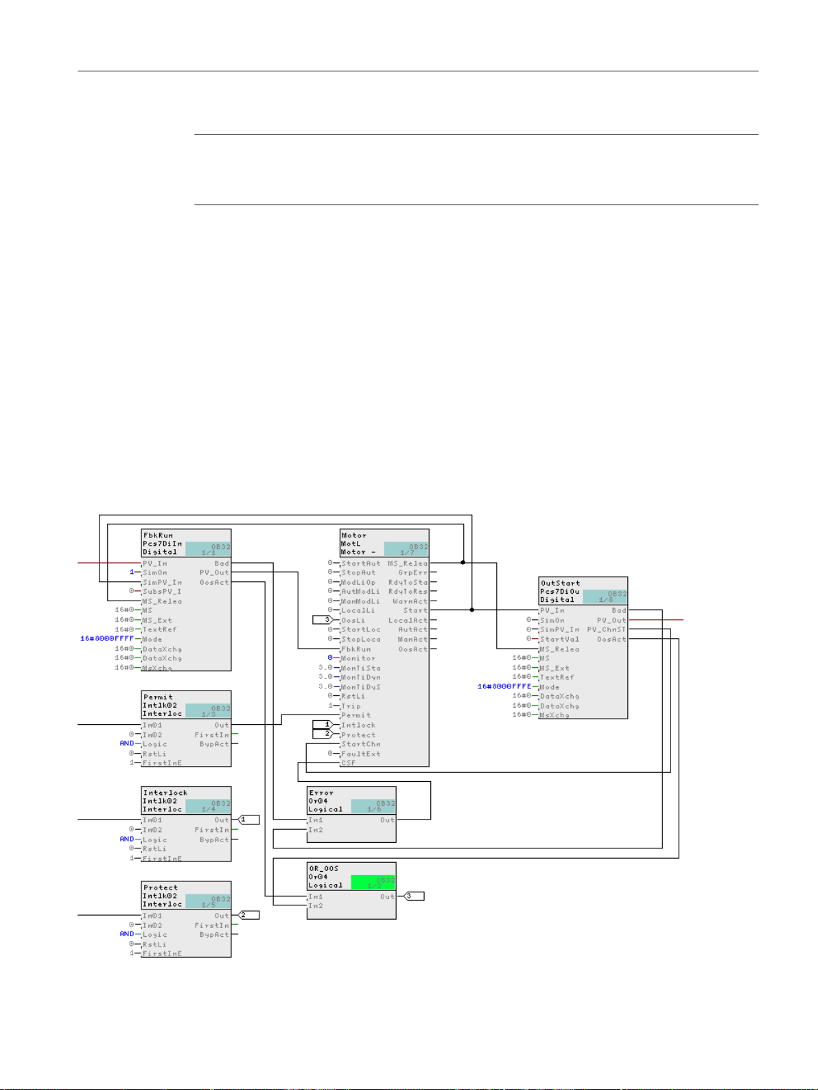
Note
If you draw a connection incorrectly:
Click on the line of the incorrect interconnection and select Edit > Delete.
6.6.15 Interconnecting blocks in the "CFC_NP111"
Prerequisites
● The "CFC_NP111" CFC is open in the CFC Editor.
● All blocks are inserted, renamed and configured.
Procedure
Creating CFCs
6.6 Working with the CFC Editor
1. Click "Start" output in the middle block "Motor".
2. Now, click "SimPV_in" input on the "FbkRun" block. The CFC Editor automatically creates
a line indicating the interconnection. The CFC should now appear as follows:
PCS 7 SMART Getting Started - Part 1 (V9.0 with APL)
Getting Started, 12/2017, A5E42181435-AA 93
Page 94
Creating CFCs
6.6 Working with the CFC Editor
6.6.16 Interconnecting blocks in the "CFC_FC111"
Prerequisites
● The "CFC_FC111" CFC is open in the CFC Editor.
● All blocks are inserted, renamed and configured.
Procedure
1. Click the "Out" output on the "SP_INT_EXT" block.
2. Now click the "SP_LiOp" input on the "DOSE" block.
The CFC Editor automatically creates a line indicating the interconnection.
3. Following the same procedure, interconnect additional blocks according to the table below.
(The "4" block is located on the CFC_LI111 chart. To do this, place the two charts side by
side.)
Block description Output Block description Input
SP_INT_EXT Out DOSE SP_ExtLi
Out DOSE SP_IntLi (Inver‐
DOSE SP CTRL_PID MV_TRK
INPUT_U PV_Out DOSE PV
PV_Out CTRL_PID PV
PV_Out 4 (in chart CFC_LI111) In1
PV_OutUnit DOSE PV_Unit
PV_OutUnit CTRL_PID PV_Unit
CTRL_PID MV OUTPUT_LMN PV_In
MV MUL In1
SP MUL In4
MUL Out INPUT_U SimPV_In
ted)
PCS 7 SMART Getting Started - Part 1 (V9.0 with APL)
94 Getting Started, 12/2017, A5E42181435-AA
Page 95
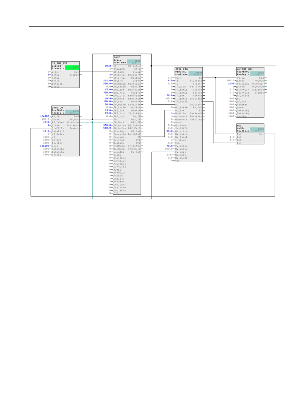
4. The CFC should now appear as follows:
Creating CFCs
6.6 Working with the CFC Editor
5. Close the chart.
6.6.17 Interconnecting blocks in the "CFC_LI111"
Prerequisites
● The "CFC_LI111" CFC is open in the CFC Editor.
● All blocks are inserted, renamed and configured.
PCS 7 SMART Getting Started - Part 1 (V9.0 with APL)
Getting Started, 12/2017, A5E42181435-AA 95
Page 96

Creating CFCs
6.6 Working with the CFC Editor
Procedure
1. Interconnect the blocks according to the table below.
Block description Output Block description Input
INPUT_U PV_Out INT_P OutTrk
INT_P Out LIA PV
4 Out INT_P In
2. The CFC should now appear as follows:
3. Close the chart.
6.6.18 Assigning parameters for the blocks in "Valve_Lean"
In PCS 7 SMART, you can prepare process tag types for the specific plant.
Prerequisites
The "Valve_Lean" CFC chart is open in the CFC Editor - saved in the "color_gs_prj_Lib\Process
tag types\Valve_Lean" folder.
PCS 7 SMART Getting Started - Part 1 (V9.0 with APL)
96 Getting Started, 12/2017, A5E42181435-AA
Page 97

Procedure
Creating CFCs
6.6 Working with the CFC Editor
1. Open the "General" tab and "Inputs/Outputs" tab in the "Object Properties" dialog box for
each block.
– Enter the parameters for all blocks according to the table below.
Block Name in project I/O Meaning Value
Pcs7DiIn FbkClose SimOn.Value Simulation ena‐
bled
Pcs7DiIn FbkClose SimPV_In.Value
(inverted after in‐
terconnection)
Pcs7DiIn FbkOpen SimOn.Value Simulation ena‐
Pcs7DiIn FbkOpen SimPV_In.Value Simulation value PV0
Simulation value PV0
bled
1
1
VlvL Valve Feature.Bit4 Set switch or but‐
– In the "General" tab, accept the default setting for "Create block icons" (no checkmark
for the blocks Interloc, Permit and Protect).
2. Click "OK" for each block. Your settings are applied.
6.6.19 Interconnecting the blocks in "Valve_Lean"
Prerequisites
● The "Valve_Lean" CFC chart is open in the CFC Editor.
● The blocks have been created in the project library and parameters are assigned.
Procedure
1. Interconnect the blocks for each chart according to the table below.
Block description I/O Block description I/O
Valve Ctrl FbkOpen SimPV_in
Valve Ctrl FbkClose SimPV_In (inverted)
1
ton mode (switch
mode)
2. Close the chart.
PCS 7 SMART Getting Started - Part 1 (V9.0 with APL)
Getting Started, 12/2017, A5E42181435-AA 97
Page 98

Creating CFCs
6.7 CFCs in the process object view
6.7 CFCs in the process object view
6.7.1 Use of the Process Object View for valve control
Introduction
Now, work on the CFC_NK111 to CFC_NK114 charts. So far, you have stored the
"VALVE_Lean" process tag type in your master data library and created the four hierarchy
folders in the plant hierarchy.
Working with the process object view
To handle identical charts, PCS 7 SMART provides you with a convenient function, namely
the process object view. This means that you do not need open each individual chart in the
CFC Editor and assign parameters; rather, you can modify values quickly in a table within the
process object view.
The following preparations are necessary for this:
● Specify I/Os in the process tag type for the process object view (Page 98)
As the process object view does not visualize all I/Os for reasons of clarity, you must define
the I/Os to be shown. You define this once in the process tag type in the master data library.
● Insert the process tag type in the individual hierarchy folders and rename them (Page 100)
You are going to copy the process tag type from the master data library to all the hierarchy
folders in which you require the valve control.
● Adapt the values of the parameters in the process object view (Page 98)
The significant advantage of the process object view is that you can edit values quickly and
easily in a table.
See also
Adapting the parameters for "CFC_NK11x" (Page 101)
6.7.2 Procedure
6.7.2.1 Defining Inputs/Outputs for the Process Object View
Prerequisites
● The color_gs project is open in SIMATIC Manager.
● The process object view is activated.
PCS 7 SMART Getting Started - Part 1 (V9.0 with APL)
98 Getting Started, 12/2017, A5E42181435-AA
Page 99

Procedure
Creating CFCs
6.7 CFCs in the process object view
1. Select the "color_gs_prj_Lib\Process tag types\Valve_Lean" object in the tree view.
2. Select Options > Process Objects > Select I/Os.
The "Filter: Select I/Os" dialog box opens.
3. Enable the "Block" check box and enter "VALVE" in the input box.
By making this setting, only "VALVE" block connections will be shown.
4. Click "OK".
The "Select I/Os" dialog box opens.
5. Click the column header of the "Parameter" column.
This will display all connections in the upper lines that are activated in the "Parameters"
column.
6. Deactivate all the checkboxes.
7. Activate the checkboxes in the "Parameters" column for the following I/Os:
– AutModLi
– Feature.Bit16
– Monitor
Note
If you click on the title of the "I/O" column, the I/Os are sorted in ascending or descending
order. This makes it easier to find what you are looking for.
PCS 7 SMART Getting Started - Part 1 (V9.0 with APL)
Getting Started, 12/2017, A5E42181435-AA 99
Page 100

Creating CFCs
6.7 CFCs in the process object view
8. Click "OK".
The "Select I/Os" dialog box closes.
9. Exit the process object view.
6.7.2.2 Inserting the "Valve_Lean" process tag type
Prerequisites
● The color_gs project is open in SIMATIC Manager.
● The Plant View is activated.
Procedure
Follow exactly the same procedure as defined for the "Motor_Lean" process tag type:
1. Select the "Valve_Lean" process tag type in the detail window of the "color_gs_prj_MP
\color_gs_prj_Lib\Process tag types" folder.
2. Insert the "Valve_Lean" process tag type in the following folders using Edit > Copy and
3. Rename the inserted process tag types according to the table below.
4. Exit the plant view.
Additional information
A detailed description is available in the section:
"How to insert the "Motor_Lean" process tag type" (Page 76).
Edit > Paste:
– color_gs_prj_MP\color_gs_prj_Prj\Plant1\RMT1\NK111
– color_gs_prj_MP\color_gs_prj_Prj\Plant1\RMT1\NK112
– color_gs_prj_MP\color_gs_prj_Prj\Plant1\RMT1\NK113
– color_gs_prj_MP\color_gs_prj_Prj\Plant1\RMT1\NK114
Hierarchy folder Rename to:
../RMT1/NK111 CFC_NK111
../RMT1/NK112 CFC_NK112
../RMT1/NK113 CFC_NK113
../RMT1/NK114 CFC_NK114
PCS 7 SMART Getting Started - Part 1 (V9.0 with APL)
100 Getting Started, 12/2017, A5E42181435-AA
 Loading...