

Siemens SIMATIC PCS 7 FOUNDATION Fieldbus Commissioning Manual

SIMATIC
Process Control System PCS 7
FOUNDATION Fieldbus
Valid for the SIMATIC PCS 7 Process Control System
software package as of V8.1 SP1 including SIMATIC
PDM V8.2 SP1
Security information
1
Commissioning Manual
Introduction
Basics of the FOUNDATION
Fieldbus
System planning
Engineering
Commissioning
Redundancy and system
changes during operation
2
3
4
5
6
7
02/2015
A5E32711026-AC
Legal information
Warning notice system
This manual contains notices you have to observe in order to ensure your personal safety, as well as to prevent
damage to property. The notices referring to your personal safety are highlighted in the manual by a safety alert
symbol, notices referring only to property damage have no safety alert symbol. These notices shown below are
graded according to the degree of danger.
DANGER
indicates that death or severe personal injury will result if proper precautions are not taken.
WARNING
indicates that death or severe personal injury may result if proper precautions are not taken.
CAUTION
indicates that minor personal injury can result if proper precautions are not taken.
NOTICE
indicates that property damage can result if proper precautions are not taken.
If more than one degree of danger is present, the warning notice representing the highest degree of danger will be
used. A notice warning of injury to persons with a safety alert symbol may also include a warning relating to property
damage.
Qualified Personnel
The product/system described in this documentation may be operated only by personnel qualified for the specific
task in accordance with the relevant documentation, in particular its warning notices and safety instructions. Qualified
personnel are those who, based on their training and experience, are capable of identifying risks and avoiding
potential hazards when working with these products/systems.
Proper use of Siemens products
Note the following:
WARNING
Siemens products may only be used for the applications described in the catalog and in the relevant technical
documentation. If products and components from other manufacturers are used, these must be recommended or
approved by Siemens. Proper transport, storage, installation, assembly, commissioning, operation and
maintenance are required to ensure that the products operate safely and without any problems. The permissible
ambient conditions must be complied with. The information in the relevant documentation must be observed.
Trademarks
All names identified by ® are registered trademarks of Siemens AG. The remaining trademarks in this publication
may be trademarks whose use by third parties for their own purposes could violate the rights of the owner.
Disclaimer of Liability
We have reviewed the contents of this publication to ensure consistency with the hardware and software described.
Since variance cannot be precluded entirely, we cannot guarantee full consistency. However, the information in
this publication is reviewed regularly and any necessary corrections are included in subsequent editions.
Siemens AG
Division Process Industries and Drives
Postfach 48 48
90026 NÜRNBERG
GERMANY
A5E32711026-AC
Ⓟ 04/2015 Subject to change
Copyright © Siemens AG 2014 - 2015.
All rights reserved

Table of contents
1 Security information......................................................................................................................................5
2 Introduction...................................................................................................................................................7
3 Basics of the FOUNDATION Fieldbus........................................................................................................11
3.1 Device integration with EDD..................................................................................................12
3.2 Device addresses...................................................................................................................14
3.3 Block model of device parameters.........................................................................................15
3.4 Capability levels (device variants)..........................................................................................18
3.5 Contact partner......................................................................................................................19
4 System planning.........................................................................................................................................21
4.1 Nodes in the FOUNDATION Fieldbus....................................................................................21
4.2 Configuration..........................................................................................................................22
5 Engineering................................................................................................................................................25
5.1 Prepare..................................................................................................................................26
5.1.1 How to integrate a device description....................................................................................26
5.2 Configuring.............................................................................................................................27
5.2.1 How to prepare a FOUNDATION Fieldbus for FF devices....................................................27
5.2.2 How to place FF devices on the FOUNDATION Fieldbus.....................................................29
5.2.3 Checking the bus parameters................................................................................................33
5.2.4 Additional notes on configuration...........................................................................................34
5.2.5 How to configure FF-internal interconnections (Control in the field)......................................35
5.2.6 “Interconnection Editor" dialog box........................................................................................37
5.2.7 Adding deleted default blocks................................................................................................39
5.2.8 How to replace an FF device.................................................................................................39
5.3 Parameter assignment...........................................................................................................40
5.3.1 How to assign parameters of the FF devices.........................................................................40
5.3.2 Bus parameters......................................................................................................................42
5.3.3 How to assign bus parameters...............................................................................................47
5.3.4 How to plan the macrocycle...................................................................................................49
5.4 Using the applications............................................................................................................52
5.4.1 Overview................................................................................................................................52
5.4.2 Identifying FF devices with SIMATIC PDM............................................................................53
5.4.3 Specifying the device identification of the FF devices (TAG name and address)..................55
5.4.4 Editing symbols (symbolic names).........................................................................................56
5.4.5 Configuring interconnections to the FF devices.....................................................................57
5.4.6 Configuring the operator station.............................................................................................58
6 Commissioning...........................................................................................................................................59
6.1 Compile and download...........................................................................................................59
6.1.1 Introduction............................................................................................................................59
FOUNDATION Fieldbus
Commissioning Manual, 02/2015, A5E32711026-AC 3

Table of contents
6.1.2 Downloading objects in the FF segment................................................................................60
6.2 Diagnostics.............................................................................................................................63
6.2.1 "Modes" and "Status" menu commands.................................................................................63
6.2.2 Performing diagnostics...........................................................................................................65
7 Redundancy and system changes during operation..................................................................................67
7.1 Redundancy...........................................................................................................................67
7.2 System changes during operation..........................................................................................68
Index...........................................................................................................................................................71
FOUNDATION Fieldbus
4 Commissioning Manual, 02/2015, A5E32711026-AC

Security information
Siemens provides products and solutions with industrial security functions that support the
secure operation of plants, solutions, machines, equipment and/or networks. They are
important components in a holistic industrial security concept. With this in mind, Siemens’
products and solutions undergo continuous development. Siemens recommends strongly that
you regularly check for product updates.
For the secure operation of Siemens products and solutions, it is necessary to take suitable
preventive action (e.g. cell protection concept) and integrate each component into a holistic,
state-of-the-art industrial security concept. Third-party products that may be in use should also
be considered. For more information about industrial security, visit http://www.siemens.com/
industrialsecurity.
To stay informed about product updates as they occur, sign up for a product-specific
newsletter. For more information, visit http://support.automation.siemens.com.
1
FOUNDATION Fieldbus
Commissioning Manual, 02/2015, A5E32711026-AC 5

Security information
FOUNDATION Fieldbus
6 Commissioning Manual, 02/2015, A5E32711026-AC
Introduction
))VHJPHQW
%XVOLQN
&RPSDFW))OLQN
%XVOLQNV%XVOLQN
))OLQN
$FWLYHILHOGGLVWULEXWRUV
))VHJPHQW
)LHOGGHYLFHV
))VHJPHQW
352),%86'3
(WKHUQHW
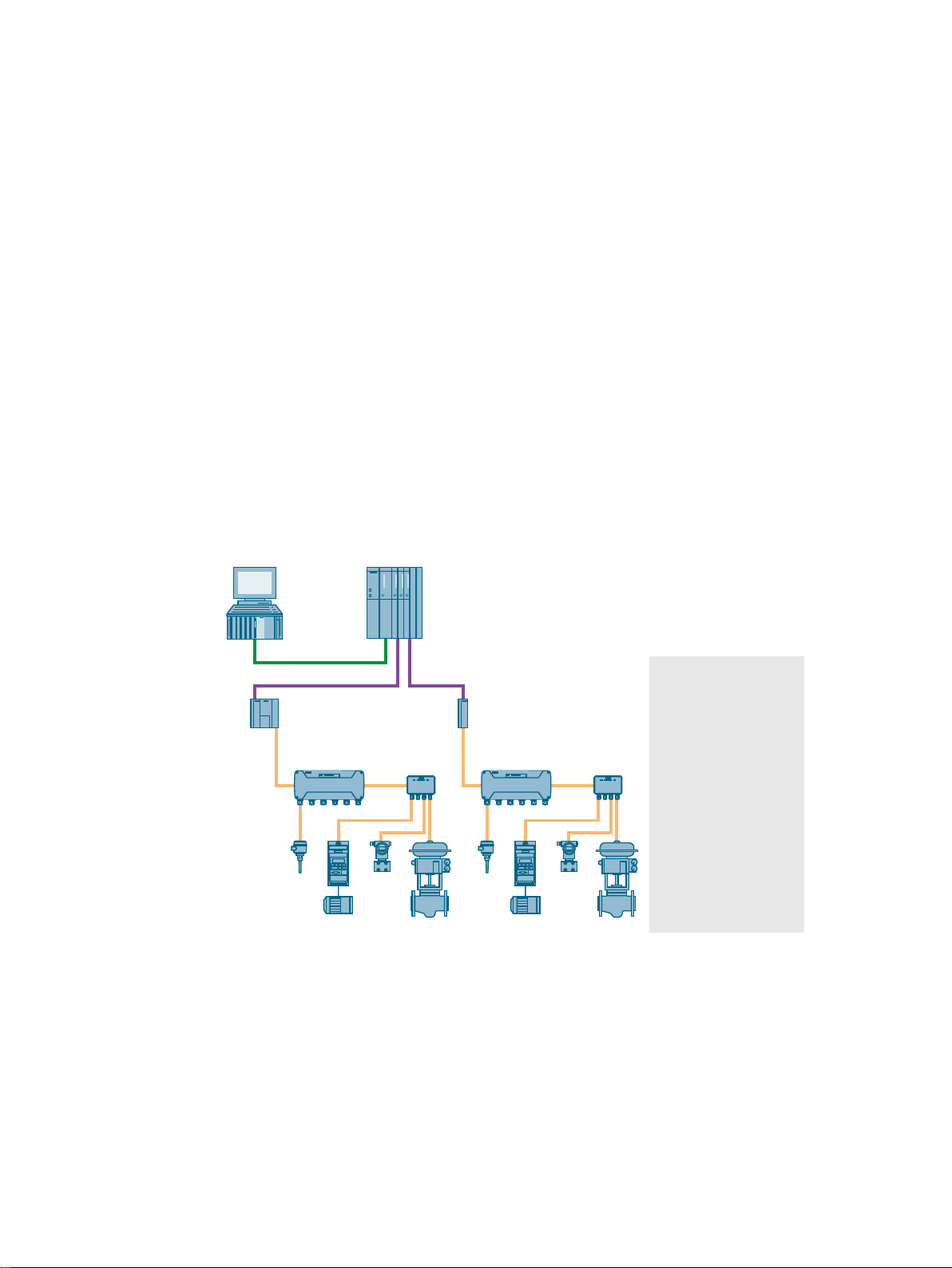
SIMATIC PCS 7 provides the option of integrating field devices on FOUNDATION Fieldbus
H1 (hereafter referred to simply as FF). FF devices are generally connected to a SIMATIC
station via a bus link on PROFIBUS DP (e.g. FF Link). Bus links are gateways between bus
systems and enable the communication connection of the bus systems.
The following bus links are typically used for the communication between PROFIBUS DP and
FOUNDATION Fieldbus in PCS 7 systems.
● FF Link
● Compact FF Link
Examples for configuration of FF segments in PCS 7
The display shows an example of the connection of FF devices to the automation system. The
additional use of the active field distributor enables mutual decoupling in case of FF device
faults.
2
SIMATIC PCS 7 supports the connection of FF devices
FOUNDATION Fieldbus
Commissioning Manual, 02/2015, A5E32711026-AC 7
SIMATIC PCS 7 supports the connection of FF devices by way of the following functions:
● Central engineering without additional tools
● Import of the electronic device descriptions (EDD) of FF devices
(you can find additional information about this in the section "Device integration with EDD
(Page 12)")

Introduction
● Channel blocks of the PCS 7 library: Advanced Process Library (APL)
● PCS 7 Asset Management
Basic knowledge required
This documentation is intended for personnel working in the fields of configuration,
commissioning, and service.
Basic knowledge of the general use of the PC/programming device and of the use of the
Windows operating system is required.
Knowledge of the functions and configurations of the following products is required:
● SIMATIC PCS 7
● SIMATIC S7 (S7-400, STEP 7)
● SIMATIC NET
● SIMATIC PDM
Basic knowledge of the FOUNDATION Fieldbus is required.
An understanding of the operating instructions of the bus link is required.
Information for FF users
Users who have configured only FF up to now can acquire the necessary knowledge of PCS
7 with the help of the PCS 7 documentation. You can find an introduction to working with PCS 7
in the
Conventions
Some of the information in this documentation applies to several components. To ensure that
the products to which such information applies are clearly identifiable, we have used the
following designations:
Designation Validity
Bus link The associated information pertains to the components you can order as a
FF Link The associated information pertains to the FF Link. The following modules
Compact FF Link The associated information pertains to the Compact FF Link. The following
SIMATIC PCS 7 Process Control System; PCS 7 - Getting Started
gateway from PROFIBUS DP to the FOUNDATION Fieldbus for an automa‐
tion system.
are used in this bus link:
● IM 153-2 FF
● FDC 157
The FF Link can be configured redundantly.
module is used in this bus link: Compact FF Link (IM 655-5 FF)
The Compact FF Link can be configured redundantly.
documentation.
FOUNDATION Fieldbus
8 Commissioning Manual, 02/2015, A5E32711026-AC

Changes compared to older versions
Below, you can find an overview of the most important changes in the documentation compared
to the previous version:
As of PCS 7 V8.1 SP1
● Use of the "Compact FF Link (IM 655-5 FF)" bus link
As of PCS 7 V8.1
SIMATIC PCS 7, together with SIMATIC PDM as of V8.2, is certified for Class 61 hosts (Host
Interoperability Support Test, Host: Profile Classes 61a / 61b).
The following FF functions can be implemented with it for example:
● Cross block references (device level access)
● Multiple capability levels
● Instantiable blocks
Introduction
FOUNDATION Fieldbus
Commissioning Manual, 02/2015, A5E32711026-AC 9

Introduction
FOUNDATION Fieldbus
10 Commissioning Manual, 02/2015, A5E32711026-AC

Basics of the FOUNDATION Fieldbus
FOUNDATION Fieldbus (FF) and PROFIBUS PA operate according to IEC 61158-2. The
communication on the fieldbus and the voltage supply of the bus nodes are combined in one
shielded two-wire cable. Up to 32 bus nodes are possible on one FF segment (bus link +
maximum of 31 field devices). Data packets are modulated and transmitted on the supply
voltage for the fieldbus nodes. The transfer rate is 31.25 Kbps.
The most important distinctions between PROFIBUS PA and FOUNDATION Fieldbus
Licensing
● You need the "PDM Foundation Fieldbus" license key to work with SIMATIC PDM.
Operating mode
● PROFIBUS PA devices are operated in master/slave mode.
● FF devices are operated in publisher/subscriber mode.
Connection to PROFIBUS DP
● PROFIBUS PA devices are connected to up to five FDC 157 DP/PA couplers via DP/PALink (redundancy with 2 fieldbus couplers possible).
3
● FF devices are connected to the automation system via a bus link. The following bus links
are approved for PCS 7:
– FF Link
Configuration with an IM 153-2 FFinterface module and FDC 157 fieldbus coupler
(redundancy with 2 fieldbus couplers possible)
– Compact FF Link
Configuration with Compact FF Link (redundancy with 2 Compact FF Link possible)
Communication with the automation system
● PROFIBUS PA devices only communicate via the automation system. An exception to this
rule is the direct access to a PA device.
● FF devices can communicate on the FF segment without involvement of the automation
system. The name of this function is "Control in the field" (CiF). CiF enables technological
function between FF devices.
Terms used for FOUNDATION Fieldbus (FF)
Publisher and Subscriber
In the time period during which an FF device sends data to the FF, it is referred to as the
Publisher.
FOUNDATION Fieldbus
Commissioning Manual, 02/2015, A5E32711026-AC 11

Basics of the FOUNDATION Fieldbus
3.1 Device integration with EDD
In the time period during which an FF device reads data from the FF, it is referred to as the
Subscriber. The schedule defines when a Publisher sends data and when a Subscriber
receives data.
Client and Server
The client-server principle is used for acyclic services.
Communication types
Two types of communication are used with FF:
● Cyclic communication
Cyclic communication is defined in the schedule. It includes tasks such as closed-loop
control of process values (control functions) and operator control and monitoring functions.
● Acyclic communication
Acyclic communication is used for transmitting unscheduled information. Examples of this
information are:
– Maintenance/diagnostic data
– Configuration data
– Parameter assignment data
Schedule and LAS (Link Active Scheduler)
The time at which an FF device transmits or reads cyclic data is defined in the schedule for
the FF. The schedule prevents conflicts on the FF segment during communication. A bus link
performs the LAS function in PCS 7 during normal operation. If no bus link is online on the FF
segment, suitable FF devices (Link Master) can assume the LAS function.
Macro cycle
The macro cycle is a time period that must be defined for each system. The following tasks
must be performed during this time period:
● All FF devices must be processed.
● Information must be transmitted by means of acyclic communication.
The FF specification recommends that at least 50% of the bus time be kept free for acyclic
communication.
3.1 Device integration with EDD
FF devices are integrated in the control system in PCS 7 using the application SIMATIC PDM.
Note
Integrating FF device descriptions
Device descriptions of FF devices that you do not find on the "Device Library..." DVD provided
with SIMATIC PDM must be modified before the integration. Please speak with your contact
(Page 19) about this.
FOUNDATION Fieldbus
12 Commissioning Manual, 02/2015, A5E32711026-AC

Liability
Siemens explicitly declines any liability for damages resulting from the use of the following
device description files and use in conjunction with the associated devices:
● For device-specific device description files for non-Siemens devices, the Siemens warranty
only applies up to the interface.
● For device description files integrated through catalogs
NOTICE
Important note on the device description files included with the SIMATIC PDM
The device description files of non-Siemens field devices have not been developed by
Siemens and are included with the shipped products free of charge. The licensee is entitled
to use the device description files of these devices in the same manner as a trial license
in accordance with the general terms and conditions for the supply of software for
automation and drive technology. This right of use may be exercised by the licensee as
long as the right of use for the PDM software is in effect.
Standardized device descriptions
Basics of the FOUNDATION Fieldbus
3.1 Device integration with EDD
Standardized device descriptions enable intelligent field devices from different manufacturers
to be integrated in different control systems. The IEC 61804-3 standard governs the structure
of device descriptions (DD). This standard was developed in cooperation with the following
organizations:
● PROFIBUS User Organization (PNO)
● Hart Communication Foundation (HCF)
● Fieldbus FOUNDATION
● OPC Foundation
The device descriptions are based on the EDDL (Electronic Device Description Language).
Information in device descriptions
Device descriptions contain all information required for correct interpretation of device data.
● Pre-defined device descriptions (standard DDs) describe the key parameters. These
standard DDs are available from the user organizations, for example, through the Fieldbus
FOUNDATION.
FF devices can interpret and display the data and functions of this standard DD. The basic
functions of the user interface are stored in the standard DD.
● Device-specific functions and parameters can be stored in an extended device description.
● The device description specifies the rules for the instantiation of blocks:
– Number and type of the initially automatically created, deletable blocks (default blocks)
– Maximum of all instantiable blocks
– Maximum of the instantiable blocks of a certain type
– Hardware-dependent, type-specific limitations of the maximum number of blocks
FOUNDATION Fieldbus
Commissioning Manual, 02/2015, A5E32711026-AC 13

Basics of the FOUNDATION Fieldbus
3.2 Device addresses
Additional information
● IEC 61804-2
● IEC 61804-3
● Section "Block model of device parameters (Page 15)"
3.2 Device addresses
Address ranges in PCS 7
The following table shows the distribution of address ranges for the FF segment:
Address range Information on the address range
0 to 15 Reserved by the system (use not permitted)
16 to 19 Reserved range for bus link:
Ad‐
dress
16: IM for PROFIBUS DP
17 with redundant configuration: right IM with redundant configuration: right Compact FF
20 to 35 SIEMENS Polled Range:
reserved for cyclical data exchange with FF devices (optional expansion up to 50)
36 to 231 SIEMENS Unpolled Range:
FF devices in this address range are only recognized if the "standard range" has been extended. You
can find information on this in the section "Specifying the device identification of the FF devices (TAG
name and address) (Page 55)".
232 to 247 SIEMENS reserve range:
Reserved address range for new FF devices or FF devices that are not in operation, and for FF devices
that are only temporarily connected
248 to 251 Range for temporary FF devices
● Devices that are made available and that require a device address.
● Devices that are moved to this range by the automatic address conflict resolution (up to four FF
● Devices that were removed from processing (using the "Reset address" function)
Note for users:
Make sure that there are always free addresses in this range. This enables automatic assignment of a
temporary address to new FF devices. Some actions of SIMATIC PDM are based on the availability of
this address range (e.g., "Assign address and TAG").
252 to 255 Range for LAS-compliant temporary FF devices
FF Link (IM 153‑2 und FDC 157) Compact FF Link (IM 655‑5 FF with integrated
(with redundant configuration: left IM)
devices)
You will find information on this in the online help of SIMATIC PDM
Field Device Coupler)
Compact FF Link
(with redundant configuration: left Compact FF
Link)
Link
Automatic address conflict resolution for device addresses
Connected FF devices will be detected automatically at the FF segment.
FOUNDATION Fieldbus
14 Commissioning Manual, 02/2015, A5E32711026-AC

Basics of the FOUNDATION Fieldbus
3.3 Block model of device parameters
In the case of an address conflict, one of the FF devices affected by the address conflict will
automatically be assigned a temporary address during runtime. The procedure is repeated
automatically until the existing address conflicts are resolved.
The device addresses 248 to 251 have been reserved for automatic address conflict resolution
at the FF segment.
Note
The device address that was assigned to an FF device by automatic address conflict resolution
will not be saved in the FF device.
Note the following when you use automatic address conflict resolution:
● You may not connect or switch on for the first time more than 4 new FF devices with the
same address at the FF segment.
● You have to change the device addresses of FF devices that have been assigned to one
of the temporary addresses.
3.3 Block model of device parameters
The parameters (functions and data of an FF device) are assigned to block types in the device
descriptions of the FF devices:
Block type Note
Resource block One resource block per FF device.
Function block Multiple function blocks are possible for an FF device
Transducer block Multiple transducer blocks are possible for an FF device.
Note
Parameter assignment with SIMATIC PDM
The SIMATIC PDM application is used in PCS 7 for parameter assignment of the FF devices.
Block types
Resource block
The resource block contains device-specific information of the manufacturer.
Examples of this are:
● Manufacturer
● Device type
● Device number
● Serial number
● Hardware version
● Firmware version
FOUNDATION Fieldbus
Commissioning Manual, 02/2015, A5E32711026-AC 15

Basics of the FOUNDATION Fieldbus
3.3 Block model of device parameters
Function block
Function blocks provide information about the functions available in an FF device as well as
their tasks. The schedules of the clocked data transmission defined in the schedule are based
on these function blocks. Access to the functions and their inputs and outputs is defined via
the function blocks. Each FF device has at least one function block.
Standard profiles for function blocks are defined in the FF specification. A description of the
basic functions is possible with the help of these standard profiles.
Table 3-1 Examples of the most important standard profiles for function blocks:
Block designation Function
AI Analog input
AO Analog output
B Offset (bias)
CS Control selector
DI Digital input
DO Digital output
ML Manual loader
PD PD controller (proportional/derivative)
PID PID controller (proportional/integral/derivative)
RA Ratio controller
Transducer block
Transducer blocks make it possible to influence the input and output variables of a function
block.
Examples of this are:
● Calibration and conversion of measured and control data
● Linearization of characteristic curves
● Conversion of physical quantities using other process data
Multiple capability levels
Some manufacturers offer FF devices in variants with a scalable scope of function and
transducer blocks. These variants are designated as capability levels in FOUNDATION
Fieldbus.
You can find information on this in the section "Capability levels (device variants) (Page 18)".
FOUNDATION Fieldbus
16 Commissioning Manual, 02/2015, A5E32711026-AC

Block types in HW Config and in SIMATIC PDM
In the device catalogs of HW Config and SIMATIC PDM, you will find the following groups of
device-specific blocks:
Basics of the FOUNDATION Fieldbus
3.3 Block model of device parameters
Property
Identifier in the configuration in
HW Config
Font in the configuration in
HW Config
Section with attributes in the
device description
Visibility in the catalog Not visible Visible Visible
Configuration Automatically created Automatically created Must be inserted manually
Deletion capability Cannot be deleted Can be deleted and re-inser‐
Permanent blocks
FB
Italic
Per instance Per instance Per block type
Default blocks
FB
Not italic Not italic
ted
Instantiable blocks
(only for devices with capabil‐
ity level)
● FB TYPE
● TB TYPE
Can be deleted
Objects of the block model
In PCS 7, applications in the PC stations assume the functions of FF-specific objects:
Engineering station
● Configuration of the FOUNDATION Fieldbus
● Interconnection of the FF devices
– Interconnections for the process image
You can find information on this in the section "How to replace an FF device (Page 39)".
– Interconnections within the FF devices
You can find information about this in the following sections:
- Section "“Interconnection Editor" dialog box (Page 37)"
- Section "How to configure FF-internal interconnections (Control in the field) (Page 35)"
Operator stations and Maintenance Station
● Output of signals
– Alarms
– Events
● Monitoring
– Process control
– Maintenance
● Long-term archiving
FOUNDATION Fieldbus
Commissioning Manual, 02/2015, A5E32711026-AC 17

Basics of the FOUNDATION Fieldbus
3.4 Capability levels (device variants)
3.4 Capability levels (device variants)
Some manufacturers offer FF devices in device variants with a scaled scope of functions.
These device variants are designated as "capability levels" in FOUNDATION Fieldbus.
Common features and differences based on capability level
Common features
● The devices use the same device description.
● The general device properties defined in the device description are identical.
Differences
● Within the capability level, the following types of function and transducer blocks are defined:
– Permanent blocks
– Initially created, deletable default blocks
– Instantiable blocks (for devices with capability level)
● The type and number of blocks can be different.
● Instantiable blocks can only be selected if at least one capability level is defined for a device.
Selecting the capability level in the device catalogs
In the device catalogs of HW Config and SIMATIC PDM, you will find capability levels at the
following place:
In the tree view as a hierarchy level below the device revision of the FF devices.
Examples
Device without capability level Device with capability level Device with instantiable blocks
Device
● Device revision
● Device revision
Device
● Device revision
● Device revision
– Capability level 1
– Capability level 2
Device
● Device revision
● Device revision
– Capability level 1
– Capability level 2
- Instantiable block FB TYPE <...>
- Instantiable block FB TYPE <...>
Configuring the capability level
1. In the hardware configuration, select the capability level supported by your device.
2. Configure the blocks for the device (add/delete).
Observe the following sections:
– You can find information about the properties of the blocks in the section "Block model
of device parameters (Page 15)".
– You can find information about the device description in the section "Device integration
with EDD (Page 12)".
FOUNDATION Fieldbus
18 Commissioning Manual, 02/2015, A5E32711026-AC

Communication and downloading of FF devices with capability level
When the FF segment is downloaded, the instantiated blocks are created in the devices. You
can find additional information about downloading in the section "Downloading objects in the
FF segment (Page 60)".
The automation system (host) can only communicate with the device if the capability level of
the device matches the configured capability level.
3.5 Contact partner
Your contact partner (not for demo version)
Questions on SIMATIC STEP 7 / SIMATIC PCS 7 / hardware / SIMATIC PDM / problems with
S7 communication
Mailing address: SIEMENS AG
Customer Support
D-90475 Nuremberg, Germany
E-mail: online-support.industry@siemens.com
Internet: http://www.siemens.com/automation/service&support (http://
www.siemens.com/automation/service&support)
Basics of the FOUNDATION Fieldbus
3.5 Contact partner
Questions on devices and GSD files
Please get in touch with your contact partner at the device manufacturer.
For more information, refer to the "List of integrated devices". You will find this on the "SIMATIC
PDM Device Library 2#2015" DVD in the "\_manuals" directory.
Follow-up installations and additional information on SIMATIC PDM are available on the
Internet at "http://www.siemens.com/simatic-pdm (www.siemens.de/simatic-pdm)".
FOUNDATION Fieldbus
Commissioning Manual, 02/2015, A5E32711026-AC 19

Basics of the FOUNDATION Fieldbus
3.5 Contact partner
FOUNDATION Fieldbus
20 Commissioning Manual, 02/2015, A5E32711026-AC

System planning
4.1 Nodes in the FOUNDATION Fieldbus
An FF segment contains all nodes communicating via the FOUNDATION Fieldbus. The
following information is used for the system-specific optimization of FF segments.
Size of the process image
An FF segment is restricted to the size of the process image of the bus link (max. 244 bytes I/
O in each case).
The 244 bytes for inputs can be divided among the FF devices:
● Digital inputs (2 bytes per value, however maximum 40 DI)
● Analog inputs (5 bytes per value, however maximum 40 AI)
The 244 bytes for outputs can be divided among the FF devices:
● Digital outputs (2 bytes per value, however maximum 40 DO)
● Analog outputs (5 bytes per value, however maximum 40 AO)
A maximum of 64 bytes can be used for outputs and 64 bytes for inputs for each FF device.
4
Nodes in an FF segment
The maximum number of nodes in an FF segment depends on the requirements of a plant
regarding update times.
Typical number of FF devices that are integrated in a plant in an FF segment: 8 to 10 (maximum
number 31)
The time for a macro cycle is influenced primarily by the share of cyclic communication. This
share depends on the following factors:
● Properties of the FF devices used in the FF segment
● Number of input values and output values of all components connected to the FF segment
You can specify a target value for the macro cycle as well as for the ratio between the cyclic
and acyclic share. The schedule is calculated for these conditions.
If a mean time of approximately 30 ms is assumed for the output of a value from FF devices,
and the block run time is considered as acyclic bus time, then the minimum macro cycle for
15 transmitted values will be approximately one second. The time for output of a value depends
on the device in question.
FOUNDATION Fieldbus
Commissioning Manual, 02/2015, A5E32711026-AC 21

System planning
4.2 Configuration
Sample calculation
● 15 x 30 ms = 450 ms, corresponds to the cyclic bus time
● Reserved bus time for acyclic communication
● Recommended macro cycle = between 1500 ms and 9000 ms
Current consumption
The permissible current consumption of all components on an FF segment depends on the
type of bus link:
● FF Link: Maximum 1 A
● Compact FF Link: Maximum 500 mA
I/O data
The parameters, inputs and outputs of FF devices are distributed over function blocks. An FF
device can have several function blocks. Only configure the required I/O data of an FF device.
The number of processed function blocks has an effect on the macro cycle.
1050 ms (recommended 70%), 450 ms (recommended, at least 50%)
4.2 Configuration
Hardware
Always connect an FF segment to the automation system via PROFIBUS DP. You need a
suitable bus link for the transition between PROFIBUS DP and the FF segment.
The bus link can be operated on the integrated line of the CPU if the CPU supports the data
record gateway.
The table shows possible CPU versions:
CPU type As of version
SIMATIC S7 41x V5.1
SIMATIC S7 41xH V6.0
WinAC RTX V4.6
Network configuration
The following structures are typical for the configuration of FF segments in PCS 7:
● Line
● Redundant configuration (see also section "Redundancy (Page 67)")
FOUNDATION Fieldbus
22 Commissioning Manual, 02/2015, A5E32711026-AC
 Loading...