

Page 1

Preface
Basics of Fault Tolerance
1
2
SIMATIC
Process Control System PCS 7
Fault-tolerant Process Control
Systems (V8.0)
Function Manual
Fault-tolerant Solutions in
PCS 7
Advantages of fault-tolerant
components
Component Replacement
and Plant Changes
Failure, Switchover and
Return of Fault-tolerant
Components
Diagnostics
3
4
5
6
7
03/2012
A5E02779471-02
Page 2

Legal information
Warning notice system
This manual contains notices you have to observe in order to ensure your personal safety, as well as to prevent
damage to property. The notices referring to your personal safety are highlighted in the manual by a safety alert
symbol, notices referring only to property damage have no safety alert symbol. These notices shown below are
graded according to the degree of danger.
DANGER
indicates that death or severe personal injury will result if proper precautions are not taken.
WARNING
indicates that death or severe personal injury may result if proper precautions are not taken.
CAUTION
with a safety alert symbol, indicates that minor personal injury can result if proper precautions are not taken.
CAUTION
without a safety alert symbol, indicates that property damage can result if proper precautions are not taken.
NOTICE
indicates that an unintended result or situation can occur if the relevant information is not taken into account.
If more than one degree of danger is present, the warning notice representing the highest degree of danger will be
used. A notice warning of injury to persons with a safety alert symbol may also include a warning relating to property
damage.
Qualified Personnel
The product/system described in this documentation may be operated only by personnel qualified for the specific
task in accordance with the relevant documentation, in particular its warning notices and safety instructions. Qualified
personnel are those who, based on their training and experience, are capable of identifying risks and avoiding
potential hazards when working with these products/systems.
Proper use of Siemens products
Note the following:
WARNING
Siemens products may only be used for the applications described in the catalog and in the relevant technical
documentation. If products and components from other manufacturers are used, these must be recommended or
approved by Siemens. Proper transport, storage, installation, assembly, commissioning, operation and
maintenance are required to ensure that the products operate safely and without any problems. The permissible
ambient conditions must be complied with. The information in the relevant documentation must be observed.
Trademarks
All names identified by ® are registered trademarks of Siemens AG. The remaining trademarks in this publication
may be trademarks whose use by third parties for their own purposes could violate the rights of the owner.
Disclaimer of Liability
We have reviewed the contents of this publication to ensure consistency with the hardware and software described.
Since variance cannot be precluded entirely, we cannot guarantee full consistency. However, the information in
this publication is reviewed regularly and any necessary corrections are included in subsequent editions.
Siemens AG
Industry Sector
Postfach 48 48
90026 NÜRNBERG
GERMANY
A5E02779471-02
Ⓟ 05/2012 Technical data subject to change
Copyright © Siemens AG 2012.
All rights reserved
Page 3

Table of contents
1 Preface.........................................................................................................................................................7
2 Basics of Fault Tolerance...........................................................................................................................13
2.1 Rationale for using fault-tolerant process control systems..........................................................13
2.2 System-wide availability analyses...............................................................................................15
2.3 PCS 7 redundancy concept.........................................................................................................16
2.4 Overview of the PCS 7 redundancy features..............................................................................19
2.5 Features for the configuration phase...........................................................................................20
2.6 Features for the commissioning and operation phases...............................................................20
2.7 Features for servicing and system expansions...........................................................................22
2.8 Definition of availability................................................................................................................23
2.9 Definition of the standby modes..................................................................................................23
2.10 Redundancy nodes......................................................................................................................24
3 Fault-tolerant Solutions in PCS 7................................................................................................................27
3.1 Solutions for the I/O.....................................................................................................................27
3.1.1 Redundant I/O.............................................................................................................................28
3.1.2 Switched I/O................................................................................................................................30
3.1.3 Components in the distributed I/O...............................................................................................32
3.1.3.1 Redundant interface modules in distributed I/O..........................................................................32
3.1.3.2 Redundant I/O modules...............................................................................................................33
3.1.3.3 Redundant actuators and sensors...............................................................................................34
3.2 Solutions for automation systems................................................................................................35
3.2.1 S7-400H hardware components..................................................................................................36
3.2.2 How the SIMATIC S7-400H AS operates....................................................................................39
3.3 Solutions for communication.......................................................................................................39
3.3.1 Network components...................................................................................................................41
3.3.2 Media Redundancy Protocol.......................................................................................................45
3.3.3 Solutions for the terminal bus......................................................................................................46
3.3.3.1 Connecting PC stations to the terminal bus................................................................................46
3.3.3.2 Fault-tolerant terminal bus...........................................................................................................47
3.3.3.3 Redundant, fault-tolerant terminal bus........................................................................................49
3.3.3.4 Redundant, fault-tolerant terminal bus based on the Parallel Redundancy Protocol (PRP).......50
3.3.3.5 Redundant, fault-tolerant terminal bus based on the INTEL TEAM mode..................................52
3.3.4 Solutions for the plant bus...........................................................................................................56
3.3.4.1 Connecting PC stations to the plant bus.....................................................................................56
3.3.4.2 Fault-tolerant plant bus................................................................................................................57
3.3.4.3 Redundant, fault-tolerant plant bus.............................................................................................59
3.3.5 Solutions for the fieldbus.............................................................................................................62
3.3.5.1 Redundant PROFIBUS DP..........................................................................................................62
3.3.5.2 Fault-tolerant fieldbus based on PROFINET...............................................................................64
Fault-tolerant Process Control Systems (V8.0)
Function Manual, 03/2012, A5E02779471-02 3
Page 4

Table of contents
3.3.5.3 Gateway between redundant and non-redundant PROFIBUS DP..............................................65
3.3.5.4 Connection of PROFIBUS PA to PROFIBUS DP........................................................................66
3.3.5.5 Fault-tolerant PROFIBUS PA......................................................................................................68
3.3.5.6 Connecting the FOUNDATION Fieldbus to PROFIBUS DP........................................................72
3.3.5.7 Fault-tolerant FOUNDATION Fieldbus........................................................................................74
3.4 Solutions for integrating a PCS 7 plant in a domain....................................................................77
3.5 Solutions for OS servers..............................................................................................................77
3.6 Solutions for OS clients...............................................................................................................81
3.6.1 Additional OS clients...................................................................................................................81
3.6.2 Permanent operability..................................................................................................................81
3.7 Solutions for SIMATIC BATCH....................................................................................................82
3.8 Solutions for Route Control server..............................................................................................85
3.9 Solutions for engineering station.................................................................................................87
3.10 Time synchronization...................................................................................................................88
4 Advantages of fault-tolerant components...................................................................................................89
4.1 Creating and expanding a project with pre-configured stations..................................................89
4.2 SIMATIC H Station......................................................................................................................89
4.2.1 Overview of configuration tasks...................................................................................................89
4.2.2 How to add a SIMATIC H station to your project.........................................................................90
4.2.3 How to insert synchronization modules into the H CPU..............................................................91
4.2.4 How to configure redundant communication processors.............................................................93
4.2.5 How to set the failure reaction of the input/output modules on the CPU.....................................95
4.3 Communication connections.......................................................................................................96
4.3.1 Overview of configuration tasks...................................................................................................96
4.3.2 Configuring the connection to the terminal bus...........................................................................97
4.3.2.1 How to configure the redundant terminal bus on the basis of the Parallel Redundancy Protocol97
4.3.2.2 How to configure the redundant terminal bus on the basis of the INTEL TEAM mode ..............97
4.3.2.3 How to connect singular components to the redundant terminal bus on the basis of the Parallel
Redundancy Protocol................................................................................................................100
4.3.3 How to configure a fault-tolerant plant bus................................................................................100
4.3.4 How to configure a redundant PROFIBUS DP..........................................................................102
4.3.5 How to configure a fault-tolerant fieldbus on the basis of PROFINET.......................................105
4.3.6 How to configure the redundant PROFIBUS PA.......................................................................107
4.4 Distributed I/O............................................................................................................................109
4.4.1 Overview of configuration tasks.................................................................................................109
4.4.2 How to configure the redundant interface for the I/O device.....................................................110
4.4.3 How to configure redundant I/O modules..................................................................................112
4.4.4 How to configure the redundancy for HART field devices.........................................................116
4.4.5 How to configure the Y Link.......................................................................................................119
4.4.6 Configuring DP/PA Link.............................................................................................................122
4.4.7 Configuring FF Link...................................................................................................................124
4.4.8 Configuration of redundant signals............................................................................................126
4.5 Operator stations.......................................................................................................................127
4.5.1 Overview of configuration tasks.................................................................................................127
4.5.2 How to configure an OS server and its redundant OS partner server.......................................127
4.5.3 How to configure a central archive server and its redundant archive partner server................130
Fault-tolerant Process Control Systems (V8.0)
4 Function Manual, 03/2012, A5E02779471-02
Page 5

Table of contents
4.5.4 How to set the redundancy of the central archive server..........................................................133
4.5.5 How to set the project paths of the destination OS and standby OS........................................134
4.5.6 How to configure a redundant connection between an OS and AS..........................................135
4.5.7 How to configure redundancy for OS servers on the engineering station.................................138
4.5.8 How to set the redundancy connection for OS servers.............................................................141
4.5.9 How to assign an S7 program to an OS....................................................................................142
4.5.10 How to configure an OS client...................................................................................................144
4.5.11 How to configure an OS client for permanent operability..........................................................145
4.5.12 How to download a SIMATIC PCS 7 project to the target systems...........................................148
4.5.13 Evaluating the "@RM_MASTER" Redundancy Variables with Scripts......................................149
4.6 SIMATIC BATCH Stations.........................................................................................................149
4.6.1 Overview of configuration tasks.................................................................................................149
4.6.2 How to configure a BATCH server and its redundant BATCH partner server...........................150
4.6.3 How to configure a BATCH client..............................................................................................152
4.6.4 How to set the redundancy monitoring of BATCH servers........................................................153
4.6.5 How to configure the redundancy connection for BATCH servers on the engineering station..154
4.6.6 How to set the redundancy connection for BATCH servers......................................................155
4.6.7 How to download the target systems for SIMATIC BATCH.......................................................156
4.7 SIMATIC Route Control stations...............................................................................................157
4.7.1 Overview of configuration tasks.................................................................................................157
4.7.2 How to configure a Route Control server and its redundant Route Control partner server.......157
4.7.3 How to configure a Route Control client....................................................................................160
4.7.4 How to configure a redundant connection between a Route Control server and AS................162
4.7.5 How to set the redundancy connection for Route Control servers............................................165
4.7.6 How to set the redundancy of the Route Control servers..........................................................166
4.7.7 How to download the target systems for Route Control............................................................166
5 Component Replacement and Plant Changes.........................................................................................167
5.1 Failure and replacement of bus components............................................................................167
5.1.1 Replacement of SIMATIC components in runtime....................................................................167
5.1.2 Replacement of bus components in runtime.............................................................................168
5.1.3 Replacement of operator stations in runtime.............................................................................169
5.1.4 Replacement of BATCH stations in runtime..............................................................................170
5.1.5 Replacement of Route Control stations in runtime....................................................................171
5.2 Plant changes in runtime...........................................................................................................172
6 Failure, Switchover and Return of Fault-tolerant Components.................................................................175
6.1 I/O..............................................................................................................................................175
6.1.1 Failure of redundant interface modules.....................................................................................175
6.1.2 Failure of redundant I/O modules..............................................................................................175
6.2 Automation system....................................................................................................................177
6.2.1 Failure of the master CPU.........................................................................................................177
6.2.2 Failure of a fiber-optic cable......................................................................................................178
6.3 Communication..........................................................................................................................180
6.3.1 Failure of redundant bus components.......................................................................................180
6.4 OS server..................................................................................................................................181
6.4.1 Failure, failover and restarting of redundant OS servers...........................................................181
6.5 BATCH Server...........................................................................................................................186
6.5.1 Reaction of BATCH servers to failure........................................................................................186
Fault-tolerant Process Control Systems (V8.0)
Function Manual, 03/2012, A5E02779471-02 5
Page 6

Table of contents
6.6 Route Control server.................................................................................................................187
6.6.1 Reaction of Route Control servers to failure..............................................................................187
6.7 OS clients..................................................................................................................................188
6.7.1 Failover reactions of OS clients with permanent operability......................................................188
6.8 BATCH clients...........................................................................................................................190
6.8.1 Failover reactions of BATCH clients..........................................................................................190
6.9 Route Control clients.................................................................................................................190
6.9.1 Failover reaction of Route Control clients..................................................................................190
6.10 Guidelines for updating a redundant OS in runtime..................................................................191
6.10.1 Introduction................................................................................................................................191
6.10.2 Overview of the required tasks..................................................................................................193
6.10.3 Phase 1: Updating Server_2......................................................................................................196
6.10.4 Phase 2: Updating OS clients interconnected with Server_2....................................................199
6.10.5 Phase 3: Downloading the connections, gateways and changes to the AS..............................201
6.10.6 Phase 4: Updating the OS clients interconnected with Server_1..............................................202
6.10.7 Phase 5: Updating Server_2......................................................................................................204
6.11 Guide to updating a redundant BATCH server in runtime.........................................................207
6.11.1 Software update (migration)......................................................................................................207
6.12 Guide to updating a redundant Route Control server in runtime...............................................207
6.12.1 Updating a redundant Route Control server in runtime.............................................................207
7 Diagnostics...............................................................................................................................................209
Index.........................................................................................................................................................211
Fault-tolerant Process Control Systems (V8.0)
6 Function Manual, 03/2012, A5E02779471-02
Page 7

Preface
Purpose of this documentation
This documentation informs you about the following aspects of configuring fault-tolerant
systems with the SIMATIC PCS 7 Process Control System:
● The basic solution concepts
● The functional mechanisms
● The most important configurations
It presents the availability solutions on all automation levels (management, process, field).
You will find references to other product manuals containing specific information for working
with individual components.
Options for accessing PCS 7 documentation
Note
PCS 7 Readme
1
The information given in the
PCS 7 manuals. Please read this
and amendments on PCS 7.
● The
● After installation of PCS 7, you can find documents such as Process Control System
As of PCS 7 V8.0, you receive basic PCS 7 system documentation with the
System; SIMATIC PCS 7
The PCS 7 Internet site http:\\www.siemens.com/pcs7-documentation (http:\
\www.siemens.com/pcs7-documentation) provides convenient access to the complete PCS 7
documentation. You can find the following for the latest PCS 7 versions:
PCS 7 Readme
important information regarding PCS 7 and takes precedence over the PCS 7
documentation supplied.
7; PCS 7 Readme
Information > <Language>.
PCS 7 Readme
PCS 7 Readme
on the
and
Process Control System; SIMATIC PCS 7
What's New in PCS 7?
DVD.
on the Internet takes precedence over all the
carefully; it contains important information
DVD contains
PCS
via the submenu SIMATIC > Product
Process Control
Fault-tolerant Process Control Systems (V8.0)
Function Manual, 03/2012, A5E02779471-02 7
Page 8

Preface
● In the section "Hardware manuals for SIMATIC PCS 7 ..."
– The manuals for components approved for a PCS 7 version
● In the section "Software manuals for SIMATIC PCS 7 ..."
– The complete system documentation
– The separate setup program for PCS 7 documentation and the PCS 7 help system for
download. After the installation of the setup program, you will find the documentation at
the following locations on the Engineering Station:
- As online help (CHM file) for the SIMATIC Manager application
- As a PDF file in the Windows Start menu with the SIMATIC documentation
– The complete documentation for PCS 7 as a
Validity of the documentation
This documentation is valid for the software package
PCS 7
, V8.0 or higher.
Required basic knowledge
General knowledge in the area of automation engineering and basic knowledge of PCS 7 is
required to understand this documentation. It is also assumed that the reader knows how to
use computers or other equipment similar to PCs (such as programming devices) with the
Windows operating system.
The configuration manuals and the Getting Started documentation for PCS 7 will provide you
with basic information regarding the use of PCS 7.
Position in the information landscape
The following documentation provides more information about fault-tolerant process control
systems and the handling of the individual components. This documentation is part of the PCS
7 software.
Manual Collection
Process Control System; SIMATIC
Manual Content
Getting Started
System PCS 7; Part 1 - Getting
Started
Configuration manual
Control System PCS 7; Engineering
System
Process Control
Process
● Creating projects
● Working with the CFC Editor
● Working with the Import/Export Wizard
● Working with the SFC Editor
● Compiling, downloading and testing
● Working with the operator station
● Basics of PCS 7
● Creating projects
● Configuring hardware
● Configuring networks
Fault-tolerant Process Control Systems (V8.0)
8 Function Manual, 03/2012, A5E02779471-02
Page 9

Preface
Manual Content
Configuration manual
Control System PCS 7; Operator
Station
Process Control System PCS 7;
Maintenance Station
manual
Configuration manual
Manual
WinCC Hardware Options,
Part 3 Redundancy
Manual
Process Control System PCS 7;
SIMATIC BATCH
Manual
Process Control System PCS 7;
SIMATIC Route Control
Manuals for PCS 7 Software Update ● Updating a PCS 7 Project with and without use of new
Manual
Automation System
S7-400H, Fault-tolerant Systems
Manual
Modifying the System in
Runtime via CiR
Manual
Distributed I/O Device ET
200M
Manual
Distributed I/O Device ET
200iSP
Process
function
WinCC
● Configuring SIMATIC connections
● Interconnecting faceplates
● Configuring operator stations
● Compiling the OS
● Installation guidelines
● Activation of the maintenance functions
● Configuration of redundancy
● Adding the OPC server
● Getting Started
● Operating principle of WinCC redundancy
● User archives
● Creating the "Project_Redundancy_Server" example project
● Description of the WinCC projects
● Server project
● Structure of a redundant WinCC system
● Operating principle of WinCC redundancy
● Configuring the OS server pair
● Guide for setting up a redundant system
● Entering the servers in Windows
● Structure of a redundant BATCH system
● Configuring the BATCH server pair
● Installation guidelines
● Setting up a redundant Route Control system
● Configuring the Route Control server pair
● Installation guidelines
functions
● Upgrading a redundant system during online operation
● Redundant SIMATIC automation systems
● Increasing availability
● System and operating modes of the S7-400H
● Linking and updating
● Modifying standard systems in runtime
● Configuration options
● Mounting
● Wiring
● Commissioning and diagnostics
● Configuration options
● Mounting
● Wiring
● Commissioning and diagnostics
Fault-tolerant Process Control Systems (V8.0)
Function Manual, 03/2012, A5E02779471-02 9
Page 10

Preface
Manual Content
Operating Instructions
NET; Industrial Ethernet Switches
SCALANCE X-200
Operating Instructions
NET; Industrial Ethernet Switches
SCALANCE X-400
Manual
SIMATIC NET
Industrial Twisted Pair and FiberOptic Networks
Manual
SIMATIC Diagnostic
Repeater for PROFIBUS-DP
Manual
SIMATIC DP/PA Coupler,
DP/PA Link and
Y Link
Documentation
SIMATIC
SIMATIC
Manual
● Configuration options
● Mounting
● Wiring
● Commissioning and diagnostics
● Configuration options
● Mounting
● Wiring
● Commissioning and diagnostics
● Networks with Industrial Ethernet and Fast Ethernet
● Network configuration
● Passive components for electrical and optical networks
● Active components and topologies
● Configuration options
● Mounting
● Wiring
● Commissioning and diagnostics
● Fundamentals of PROFIBUS PA
● DP/PA Coupler
● DP/PA Link
● DP/PA Link in redundant operation with the S7-400H
● Components released for redundancy in PCS 7
PCS 7 - Released Modules
Guide
Conventions
This manual is organized into the following topics:
● Basics of fault-tolerance in PCS 7
● Description of fault-tolerant solutions in PCS 7
● Description of configurations for various redundant components in PCS 7
● Failure scenarios and diagnostic options
● Options for quantitative analysis of fault-tolerant process control systems
● Glossary with important terms for understanding this documentation
● Index of important keywords
In this documentation, the names of elements in the software interface are specified in the
language of this documentation. If you have installed a multi-language package for the
operating system, some of the designations will be displayed in the base language of the
operating system after a language switch and will, therefore, differ from the designations used
in the documentation.
Fault-tolerant Process Control Systems (V8.0)
10 Function Manual, 03/2012, A5E02779471-02
Page 11

Changes compared to the previous version
Below, you will find an overview of the most important changes in the documentation compared
to the previous version:
● Using the redundant, fault-tolerant terminal bus
For additional information, refer to the section "Solutions for the terminal bus (Page 46)."
● Using the Process Historian and Information Server for central archiving
For additional information on this topic, refer to the
Historian
● Using a fault-tolerant fieldbus based on PROFINET
For additional information, refer to the section "Fault-tolerant fieldbus based on
PROFINET (Page 64)."
● Using the redundant FOUNDATION Fieldbus
You can find information about this in the "Fault-tolerant FOUNDATION Fieldbus
(Page 74)" section
documentation.
Preface
SIMATIC HMI; SIMATIC Process
Fault-tolerant Process Control Systems (V8.0)
Function Manual, 03/2012, A5E02779471-02 11
Page 12

Page 13

Basics of Fault Tolerance
2.1 Rationale for using fault-tolerant process control systems
Advantages of fault-tolerant components
Process control systems are responsible for controlling, monitoring and documenting
production and manufacturing processes. Due to the increasing degree of automation and the
demand for improved efficiency, the availability of these systems is playing an increasingly
important role.
Failure of the control system or any of its components can lead to costly downtime in production
and manufacturing. The expense involved in restarting a continuous process also has to be
taken into consideration along with the actual production losses resulting from a failure. In
addition, the loss of an entire batch may occur due to lost quality data. If the process is intended
to operate without supervisory or service personnel, a process control system must be
configured fault-tolerant for all of the components.
You can minimize the risk of a production failure and other detrimental effects by using faulttolerant components in a process control system. A redundant design ensures increased
availability of a control system. This means that all components involved in the process have
a backup in continuous operation that simultaneously participates in the control tasks. When
a fault occurs or one of the control system components fails, the correctly operating redundant
component takes over the continuing control task. The ultimate goal is to increase the fault
tolerance and fail-safe performance in process control systems.
2
The following applies to you as the plant operator:
The higher the cost of a production stoppage, the more you need a fault-tolerant system. The
higher initial investment usually associated with a fault-tolerant system is soon offset by the
savings resulting from decreased production downtimes.
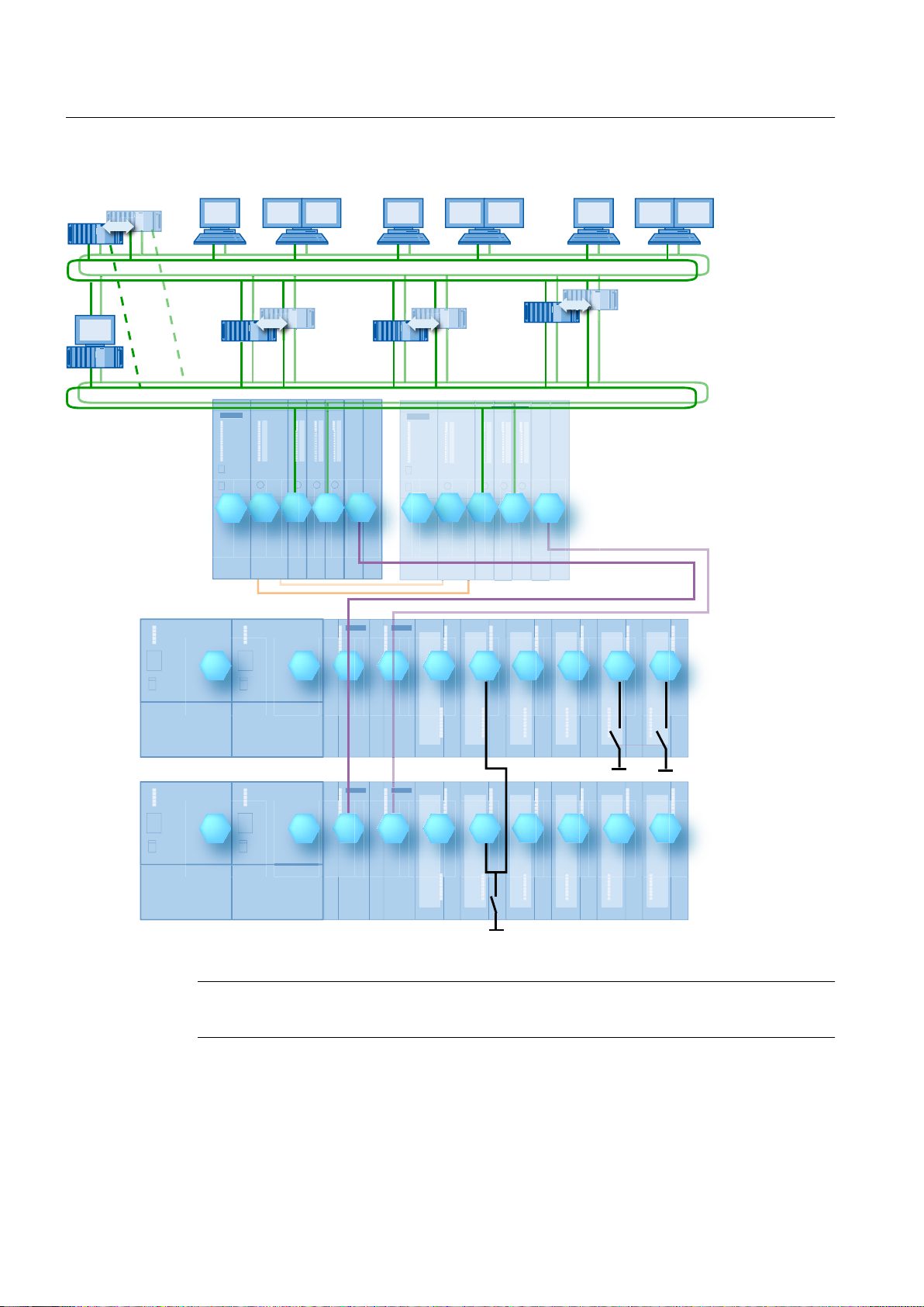
Fault-tolerant PCS 7 process control system
The following components of the PCS 7 process control system allow you to implement faulttolerance at all automation levels in the form and to the degree you require:
● Operator stations, maintenance station, central archive server, BATCH stations, Route
Control stations (management level)
● Bus system
● Automation systems (process level)
● Distributed I/O (field level)
The following figure shows an example of a fault-tolerant process control system with PCS 7
components.
Fault-tolerant Process Control Systems (V8.0)
Function Manual, 03/2012, A5E02779471-02 13
Page 14
7HUPLQDOEXV
3ODQWEXV
%$7&+FOLHQWV
06VHUYHU
5RXWH&RQWURO
VHUYHU
6HQVRU
6HQVRU
26FOLHQWV5RXWH&RQWUROFOLHQWV
26VHUYHU
%$7&+VHUYHU
(QJLQHHULQJ
6WDWLRQ
06FOLHQW
)LHOGEXV
&3
&336&3&3836&3
,036
(70
,036,0
&38
60
60
60
60
60
60
606060606060
6+
,0
&3&3
36
36
(70
Basics of Fault Tolerance
2.1 Rationale for using fault-tolerant process control systems
Legend for the above illustration:
Note
The following short designations are commonly used in this documentation.
14 Function Manual, 03/2012, A5E02779471-02
Fault-tolerant Process Control Systems (V8.0)
Page 15

Basics of Fault Tolerance
2.2 System-wide availability analyses
Short designation Meaning
Engineering
Station
OS server Operator station, PC project data station in the project form "WinCC Server"
OS client Operator station, PC visualization station in the project form "WinCC Client"
BATCH server BATCH station, PC recipe and batch data station
BATCH client BATCH station, PC recipe creation and batch visualization station
Route Control
server
Route Control
client
Plant bus, terminal
bus
S7-400H SIMATIC S7 fault-tolerant automation system, or H system for short
PS Power supply
CPU Central processing unit
CP Communications processor
IM Interface module
SM Signal module / I/O module in analog or digital form
ET 200M Distributed I/O device
Fieldbus Fieldbus for distributed I/O
Sensor Transmitters, sensors
Engineering station, PC
Route Control station, PC Route Control data station
Route Control station, PC Route Control visualization station
Bus systems for communication over Industrial Ethernet (electrical or optical)
2.2 System-wide availability analyses
Introduction
Availability must be analyzed globally for the system as a whole. Based on the degree of
availability needed, each system level, each system and each component within a level should
be evaluated. It is important to know the importance of each of these for the availability
requirements as well as the ways and means that the required availability will be achieved.
Avoiding repair time
In many industrial processes, it is not enough to simply correct the failure of a component and
then continue the process. The repair has to be made without interruption to the continuing
production process. The repair time can be considerably reduced by keeping replacement
parts in stock on site. The use of fault-tolerant components in the process control system
enables you to correct the cause of the system or component failure in runtime. The function
of the component is retained if no fault occurs in the remaining active (redundant) components
during the time a failed counterpart component is being repaired. That is, the plant continues
operation without disruption.
Fault-tolerant Process Control Systems (V8.0)
Function Manual, 03/2012, A5E02779471-02 15
Page 16

Basics of Fault Tolerance
2.3 PCS 7 redundancy concept
Avoiding impermissible signal edge transitions
A reserve system with connected backup I/O may not cause an impermissible signal edge
transition when a change occurs in the operating state (power on or off) or operating mode
(master or slave).
2.3 PCS 7 redundancy concept
Advantages of the PCS 7 redundancy concept
Fault-tolerant process control systems can be realized with SIMATIC PCS 7 at minimal cost
in all phases of a system lifecycle:
● Configuration
● Commissioning/operation
● Servicing
● Expansion
PCS 7 offers the following essential advantages:
● It provides you with system-wide scalable solutions based on the PCS 7 modular design.
Advantage: The availability can be matched to your requirements. Your process control
system can be upgraded with the SIMATIC PCS 7 components that are actually needed.
● Hardware upgrades for fault tolerance do not depend on the software configuration.
Advantage: If the user program has been configured with PCS 7, it does not have to be
adapted following a hardware upgrade. You only need to download the new hardware
configuration into the CPU.
● Fault-tolerant automation system S7-400H with CPU (types: see documentation
Control System PCS 7; Released Modules
locations.
Advantage: Protection for the spatially separated CPUs resulting in increased availability
in case of fire or explosion, for example.
● The use of redundant components in the process control system means isolated errors are
tolerated.
Advantage: The entire system does not fail when a single component in the process control
system fails. The redundant component takes over its tasks therefore allowing the process
to continue.
● Every failure of a redundant component is indicated on the OS clients in the form of a
process control message.
Advantage: You immediately receive crucial information about the status of your redundant
component. Specific components that have failed can be quickly replaced to restore the
redundancy.
), whose module racks can be set up in separate
Process
● Software updates on redundant OS servers can be performed without loss of process
operability or loss of data.
Fault-tolerant Process Control Systems (V8.0)
16 Function Manual, 03/2012, A5E02779471-02
Page 17
Overview of the PCS 7 redundancy concept
6HQVRU
DFWXDWRU
6ZLWFK
&OLHQWV26FOLHQWV%$7&+FOLHQWV5RXWH&RQWUROFOLHQWV
</LQN
%$7&+VHUYHU
5HGXQGDQWIDXOWWROHUDQWSODQWEXV5HGXQGDQWIDXOWWROHUDQWSODQWEXV
5HGXQGDQWOLQN
)DXOWWROHUDQWDXWRPDWLRQV\VWHP$6[+
$FWLYHILHOGGLVWULEXWRU
5HGXQGDQWIDXOWWROHUDQWWHUPLQDOEXV5HGXQGDQWIDXOWWROHUDQWWHUPLQDOEXV
&RQQHFWLRQRIQRQUHGXQGDQW
352),%86'3GHYLFHVWR
UHGXQGDQW352),%86'3
5RXWH
&RQWURO
VHUYHU
)DLOVDIH
)LHOGEXV
352),%863$
26VHUYHU
352),%86'3352),%86'3
(70
(70
(70
352),%86'3352),%86'3
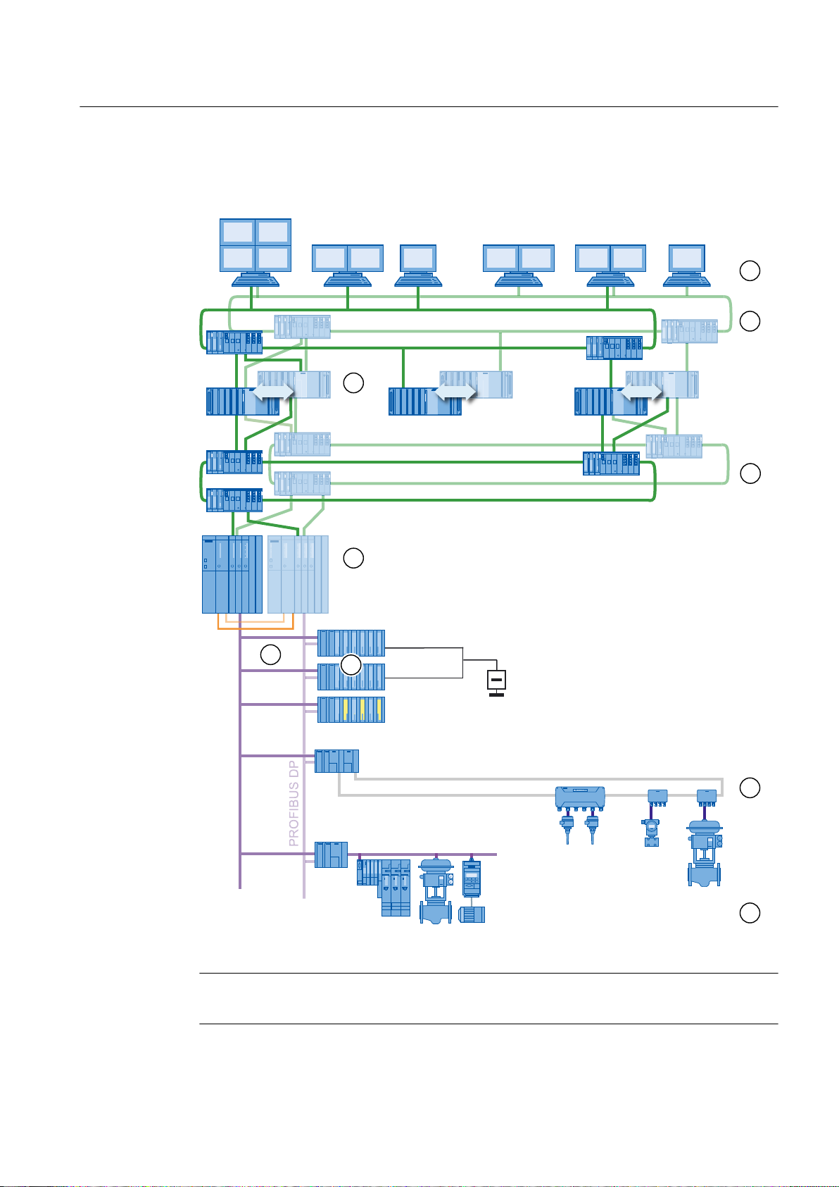
PCS 7 offers you a redundancy concept that reaches all levels of process automation.
Basics of Fault Tolerance
2.3 PCS 7 redundancy concept
Note
The numbering of the components in the illustration relates to the descriptions provided below.
Fault-tolerant Process Control Systems (V8.0)
Function Manual, 03/2012, A5E02779471-02 17
Page 18

%XV
26FOLHQW
%XV
%XV
</LQN
26FOLHQW
'3EXV
26VHUYHU
26VHUYHU
%XV
(QFRGHU
3$EXV
'33$/LQN
%XV
%XV
%XV
'33$/LQN
%XV
%XV
%XV
&3
&3
,0
,0
,0
,0
,0
,0
,0
,0
60
60
&3
&3
&3
&3
&38
&38
Basics of Fault Tolerance
2.3 PCS 7 redundancy concept
Number Description
1 Several clients (OS clients, BATCH clients, Route Control clients) can access data on a
server (OS server, BATCH server, Route Control server).
2 Communication between the operator stations (client and server) and communication with
the engineering station is over a redundant, fault-tolerant terminal bus (Industrial Ethernet).
The clients and server are connected to the terminal bus via switches.
3 The servers (OS server, BATCH server, Route Control server, maintenance server, central
archive server) can, when necessary, be set up redundantly.
4 Automation systems communicate with the OS servers/Route Control servers and
engineering stations and among themselves over the redundant, fault-tolerant plant bus
(Industrial Ethernet).
The automation systems, server and engineering station are connected to the plant bus via
switches.
5 Each part of the redundant, fault-tolerant S7-400H automation systems is connected to the
plant bus with an Ethernet communications processor (CP).
Each part of the AS be connected to several PROFIBUS DP chains. The internal PROFIBUS
DP interfaces or additional communications processors are used for the attachment.
6 The redundant connection to the DP master system is achieved using two 153-2 IM modules
in each ET 200M.
Equivalent connection via PROFINET - You can find information about this in the section
"Fault-tolerant fieldbus based on PROFINET (Page 64)"
7 Using redundant digital or analog input/output modules, you can evaluate signals from
sensors/actuators. If one of the two redundant modules fails, the input/output signal of the
functioning module are evaluated.
8 Fieldbus systems can be connected to the redundant PROFIBUS DP.
The configuration of a redundant fieldbus can be realized with a redundant gateway (for
example, PA link). The field devices are connected to the subsystem (for example,
PROFIBUS PA) via AFD, active field distributors, (or AFS when ring/coupler redundancy is
used).
9 The Y Link allows you to connect non-redundant PROFIBUS distributed I/O devices to a
redundant PROFIBUS DP.
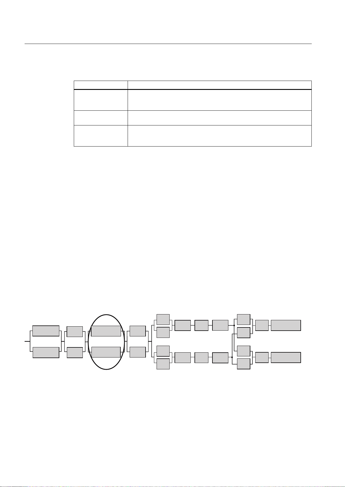
Illustration of fault tolerance using redundancy nodes
Redundancy nodes can be used to provide an overview of the fault tolerance of a process
control system. As an introductory example, the following illustration presents the process
control system shown above as a block diagram with the individual redundancy nodes.
18 Function Manual, 03/2012, A5E02779471-02
Fault-tolerant Process Control Systems (V8.0)
Page 19

2.4 Overview of the PCS 7 redundancy features
2.4 Overview of the PCS 7 redundancy features
Introduction
The easiest way to increase availability is to keep replacement parts in stock on site and to
have fast service at your disposal to replace defective components.
In this documentation, we provide you with PCS 7 software and hardware solutions that go
well beyond fast service and replacement part warehousing. It focuses on "automated faulttolerant process control systems".
System-wide, scalable solutions in PCS 7 available
Plants are divided into the following layers in PCS 7:
● Field layer
● Process layer
● Management level
The components of PCS 7 enable you to implement fault-tolerant solutions at all automation
system levels in the form and to the degree you desire. In PCS 7, individual components (such
as signal modules), complex systems (such as operator control and monitoring systems) and
complete plants can be configured in such a way that one sub-component can automatically
take on the function of another sub-component if it fails.
Basics of Fault Tolerance
You decide which components in the plant require increased availability.
The following table lists the fault-tolerant components for the three layers.
Process layer Components
Management level OS clients, maintenance clients, BATCH clients, Route Control clients
OS servers, maintenance servers, central archive servers, BATCH servers,
Route Control servers
Terminal bus (Industrial Ethernet)
Process layer Plant bus (Industrial Ethernet)
Automation system AS 412H, AS 414H, AS 416H, AS 417H
Field layer Fieldbus PROFIBUS DP, PROFIBUS PA,
Distributed I/O device ET 200M, ET 200iSP
S7-300 distributed I/O modules
PROFIBUS DP, PROFIBUS PA and HART devices
Fault-tolerant Process Control Systems (V8.0)
Function Manual, 03/2012, A5E02779471-02 19
Page 20

Basics of Fault Tolerance
2.6 Features for the commissioning and operation phases
Basics of increased availability
Increased availability in PCS 7 is based on the following principles:
● Duplication of a component
Example:
Use of duplicate signal modules
● Duplication of a component and a software component that performs an automatic failover
from active and passive components when a fault occurs.
Example of redundant components:
A signal is acquired with two signal modules and the redundancy software. The failure of
one module remains non-critical for operation of the plant.
● Technical solutions for configuring components that prevent the failure of a sub-component.
Example:
Configuration of a network in a ring structure with a component as redundancy manager.
If part of the ring is disrupted (by a defective cable, for example), the operation of the network
is maintained.
2.5 Features for the configuration phase
Features for the configuration phase
In the configuration phase, PCS 7 provides you with support with the following features.
Feature Meaning
Fault prevention through simplified
configuration of the various components
Simple integration of redundant I/O No special knowledge is needed about redundant I/O
The communication links between the
system components are configured
transparent to the application.
You do not need additional training to configure the
redundant components. Configuration can be
performed in a similar way as for standard systems.
modules.
With the HW Config or NetPro graphical user interface,
the configuration of the communication links is
performed transparent to the application.
2.6 Features for the commissioning and operation phases
Features for the commissioning and operation phases
The following table lists the features PCS 7 offers for the commissioning and operation phases.
The redundant components allows the continuation of the process of a component fails.
Operator control and monitoring of the process remains unaffected. In addition, the archiving
Fault-tolerant Process Control Systems (V8.0)
20 Function Manual, 03/2012, A5E02779471-02
Page 21

Basics of Fault Tolerance
2.6 Features for the commissioning and operation phases
of process data is not interrupted during the commissioning phase. Defective components can
be replaced in runtime.
NOTICE
If a component fails in a redundant control system, the fault tolerance is lost. This means that
another failure could potentially result in the failure of the entire system, although such
occurrences are rare (e.g., if both bus lines are severed in the case of a redundant bus
system).
You can find additional information on this in the section " Redundancy nodes (Page 24) ".
Feature Meaning Possible error / possible reason
Toleration of an isolated
error
Ensure uninterrupted
operation through
redundant components.
Ability of process to
continue to be controlled
and monitored even when
a server switchover
occurs.
Display of the master /
standby identification of
the OS server.
An isolated error is tolerated since the faulttolerant redundant component continues
the process.
The system can continue process control
without operator intervention.
If an OS server fails, the system switches
over to the configured redundant partner
server. All OS clients are automatically
switched over to the now activate OS
partner server. The process can continue
to be controlled and monitored through the
OS clients even during the failover period.
Information about the master / standby
identification of the OS server can be
requested and visualized using the OS
clients.
Fault or failure of servers and clients
Examples:
● Hard disk failure
● Operating system failure
● Connection failure
● Hard disk capacity for archiving exhausted
Error or failure of the automation system
Examples:
● Failure of power supply
● Failure of a CPU
Error or failure of the communication
Examples:
● Line break
● Electromagnetic compatibility (EMC)
Error or failure of central or distributed I/O modules
Example:
● Component failure
● Short circuit
Fault in distributed I/O devices
Examples:
● Failure of the power supply (PS)
● Failure of an interface (IM)
Failure of an individual component in a fault-
tolerant process control system.
Upgrade and expansion of the system.
Failure of the OS server
Examples:
● Operating system failure
● Hard disk defect
The master / standby identification changes if the
active OS server (master) fails.
Fault-tolerant Process Control Systems (V8.0)
Function Manual, 03/2012, A5E02779471-02 21
Page 22

Basics of Fault Tolerance
2.7 Features for servicing and system expansions
Feature Meaning Possible error / possible reason
No loss of data; gap-free
data archiving.
Permanent operability of
the control process by
configuring a preferred
server for each OS client.
Replacement of faulty
components and
reconnection to the
system in runtime.
Update of faulty
component with current
system status after being
reintegrated into the
system.
System upgrades and
expansions in runtime
Displays and
documentation
The project data are saved according to the
interval configured.
The failure of some OS clients can be
tolerated if the remaining clients continue
to be connected to the process.
The failed components can be replaced
without influencing the ongoing process
and subsequently reconnected. A
redundancy update is then performed.
Redundancy synchronization is performed
for all fault-tolerant components, for
example, a CPU or a server after return to
operation.
Redundantly designed components can be
upgraded, expanded or replaced in
runtime.
Documentation of availability, for example,
testing based on the mean time between
failure (MTBF) residual time with optional
printout.
Failure of the OS server, for example, due to a hard
disk defect.
One or more client operator stations fail, for
example, due to a hardware or software error.
Duration of the failover of the OS clients to the
redundant OS server
OS client failure: e.g., operating system
OS server failure: e.g., network adapter
Plant bus failure: e.g., wire break
Central rack failure: e.g., PS, CPU, synchronization
line, CP, SM
Fieldbus failure: e.g., defective PROFIBUS bus
connector
Failure of the distributed I/O device: e.g., PS, IM,
SM
Switching on a redundant component after a
redundancy fault. Example: Startup of the module
after a CPU is replaced with subsequent data
synchronization on the CPU conducting the
process.
Copying BIOS versions to redundant PC stations
Software updates for redundant PC stations
without utilization of new functions
Displays and documentation of a potential
component failure in advance.
2.7 Features for servicing and system expansions
Features for servicing and system expansions
PCS 7 offers the following features for servicing and system expansions:
Feature Meaning
Asset management with the maintenance station The maintenance station provides comprehensive
information for servicing and diagnostics of PCS 7
plants.
Integrated diagnostics of components (for
example, LEDs) for fast, local error detection.
Faster service from SIEMENS Customer Support. The service is on site within 2 to 48 hours to
Repairs and component expansions (upgrades,
conversions and updates) in runtime.
22 Function Manual, 03/2012, A5E02779471-02
Diagnostics of components without an additional
programming device (PG).
maintain the availability guarantee.
Repair and component expansions can be made in
a fault-tolerant system. System components are
installed redundantly so that repairs and
expansions can be made in runtime.
Fault-tolerant Process Control Systems (V8.0)
Page 23

2.8 Definition of availability
Definitions
Availability is usually defined as follows:
Quotient of MTBF and (MTBF + MTTR)
or in short form
actual operating condition / nominal operating condition.
Whereby:
● MTBF = mean time between two successive error events, repair time excluded
● MTTR = mean time to repair
Increasing the basic availability
Based on this definition, the basic availability of a standard component or a standard system
can be increased by the following:
● Reduction of error frequency
Basics of Fault Tolerance
2.9 Definition of the standby modes
● Decreasing the period necessary for repairs
A variety of measures can reduce the repair time:
– Proximity to customer service
– Replacement parts warehousing
– Repairs in runtime or repairs without downtime
With "repairs during ongoing operation", no repair time is needed in the system to correct
unscheduled operation disruptions.
2.9 Definition of the standby modes
Introduction
The availability of a system can be increased by additional components in the system (standby
components). The operating mode of these components distinguishes them from the
components that are active in process mode.
Fault-tolerant Process Control Systems (V8.0)
Function Manual, 03/2012, A5E02779471-02 23
Page 24
5HGXQGDQF\QRGHV
(QFRGHU
26FOLHQW
%XV
%XV
%XV
26VHUYHU
26FOLHQW26VHUYHU
(QFRGHU
&38
&38
%XV
%XV
%XV
60
,0
,0
60
,0
,0
&3
&3
&3
&3
&3
&3
Basics of Fault Tolerance
2.10 Redundancy nodes
Standby operating mode
Operating mode Definition
Hot standby Hot standby means the parallel redundant processing of signals in redundant
Warm standby Warm standby means the fast continuation of the aborted function by standby
Cold standby Cold standby means that there is a component of the system available that can
2.10 Redundancy nodes
Functionality
Redundancy nodes provided protection from failure of systems with redundant components.
A redundancy node is independent when the failure of one component within the node does
not affect the reliability in other nodes or in the entire system.
components. This allows a bumpless failover of the entire system to the standby
components.
components at a program continuation point.
be activated if a fault occurs. Following a restart, the newly activated component
takes over the function of the previously failed component.
The availability of a complete system is illustrated in block diagrams. In a redundant system,
a component in the redundancy node can fail without affecting the operation of the complete
system. In the chain of redundancy nodes, the weakest link determines the availability of the
entire system.
The block diagrams below present examples to illustrated this point.
Redundancy nodes without fault
The following is a block diagram showing individual redundancy nodes operating without a
fault.
24 Function Manual, 03/2012, A5E02779471-02
Fault-tolerant Process Control Systems (V8.0)
Page 25
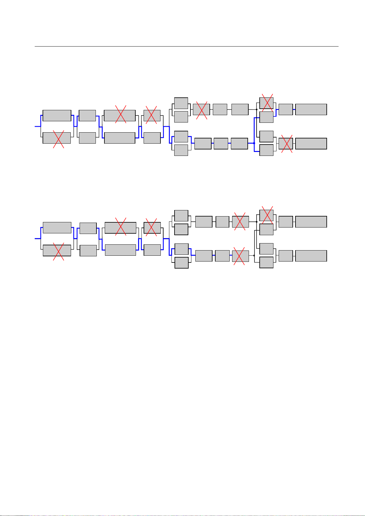
Availability of a redundancy node despite faults
6HQVRU
26&OLHQW
266HUYHU
26&OLHQW
6HQVRU
266HUYHU
%XV
%XV
%XV
%XV
%XV
%XV
&38
&38
60
,0
,0
,0
,0
&3
&3
&3
&3
&3
&3
60
6HQVRU
26&OLHQW
266HUYHU
26&OLHQW266HUYHU
6HQVRU
%XV
%XV
%XV
%XV
%XV
%XV
&38
&38
60
,0
,0
60
,0
,0
&3
&3
&3
&3
&3
&3
If a component in a redundancy node fails, the overall system continues to operate.
Total failure of a redundancy node
The following figure shows a complete system that has ceased to operate due to a failure of
the "Field bus (PROFIBUS DP)" redundancy node.
Basics of Fault Tolerance
2.10 Redundancy nodes
Fault-tolerant Process Control Systems (V8.0)
Function Manual, 03/2012, A5E02779471-02 25
Page 26

Page 27

Fault-tolerant Solutions in PCS 7
3.1 Solutions for the I/O
Introduction
In this section you will learn about the I/O systems and components that contribute to increasing
the availability of your system. This means using the distributed I/O in PCS 7.
Distributed I/O
Distributed I/O refers to modules (input/output modules and function modules) that are used
in a modular, distributed I/O device such as the ET 200M or ET 200iSP.
Distributed I/O devices are often spatially separated from the central rack and located in direct
proximity to the field devices themselves. This minimizes the requirements for wiring and
ensuring the electromagnetic compatibility. Communication connections between the CPU of
the automation system and the distributed I/O can be established with the following network
types:
● PROFIBUS DP
3
● PROFINET
In addition to the I/O devices, distributed I/O includes field devices such as actuators, weighing
systems, motor protection control equipment and all other field devices that can be integrated
in PCS 7 via the bus system.
HART devices are connected and addressed via the corresponding modules in the (ET 200M /
ET 200iSP) distributed I/O. HART devices are actuators and sensors that can be configured
per HART protocol (HART: Highway Addressable Remote Transducer).
Distributed I/O also includes bus converters such as DP/PA-Link and Y-Link . The DP/PA‑Link
enables the connection of a lower-level bus system such as PROFIBUS PA to a redundant
PROFIBUS DP.
An AS interface can be connected using AS-Interface master modules (CPs) that are used in
the distributed I/O device. This enables the connection of simple sensors and actuators to PCS
7 with AS-Interface. PCS 7 integrates other I/O levels in a project in this way.
Fault-tolerant Process Control Systems (V8.0)
Function Manual, 03/2012, A5E02779471-02 27
Page 28

Fault-tolerant Solutions in PCS 7
3.1 Solutions for the I/O
Increasing availability
The availability of the I/O can be increased through the following configuration options:
● Redundant I/O (distributed I/O)
The entire signal path up to the sensor/actuator is configured redundantly. Additional
information on this topic is available in section "Redundant I/O (Page 28)".
● Switched I/O (distributed I/O)
The communication path to the I/O (station) is redundant. There is only one input/output
module (SM) for processing a process signal.
Additional information on this topic is available in section "Switched I/O (Page 30)"
Modules for the distributed I/O
Note
Information on which modules are released for the distributed I/O in PCS 7 can be found in
the documentation
Internet at: http:\\www.siemens.com/pcs7-documentation (http:\\www.siemens.com/pcs7-
documentation).
PCS 7 - Released modules.
You will find this documentation on the
3.1.1 Redundant I/O
Redundant I/O
Redundant I/O describes the situation when the I/O modules (SM) for processing a process
signal are doubly available and can be addressed by both CPUs. The CPU signal or process
signal will continue to be processed by a functioning module even when its partner fails. The
Configuration
entire signal path up to the sensor/actuator is configured redundantly.
Note
With PCS 7, you can determine if errors in redundantly acquired signals will have an effect
of a module or channel. You can find information about this in the following sections:
● Section "Redundant input/output modules (Page 33)"
● Section "Failure of redundant input/output modules (Page 175)"
In PCS 7, you can configure redundant I/O with selected S7-300 I/O modules of ET 200M.
Fault-tolerant Process Control Systems (V8.0)
28 Function Manual, 03/2012, A5E02779471-02
Page 29
(70
[,0
(QFRGHU
5HGXQGDQWLQSXW
PRGXOH
6+
352),%86'3
(70+6\VWHP
%XV
60LQ(70
,,
60LQ(70
,
6HQVRU
%XV
&38,0
&38
&3
&3
,0
&3
&336
36
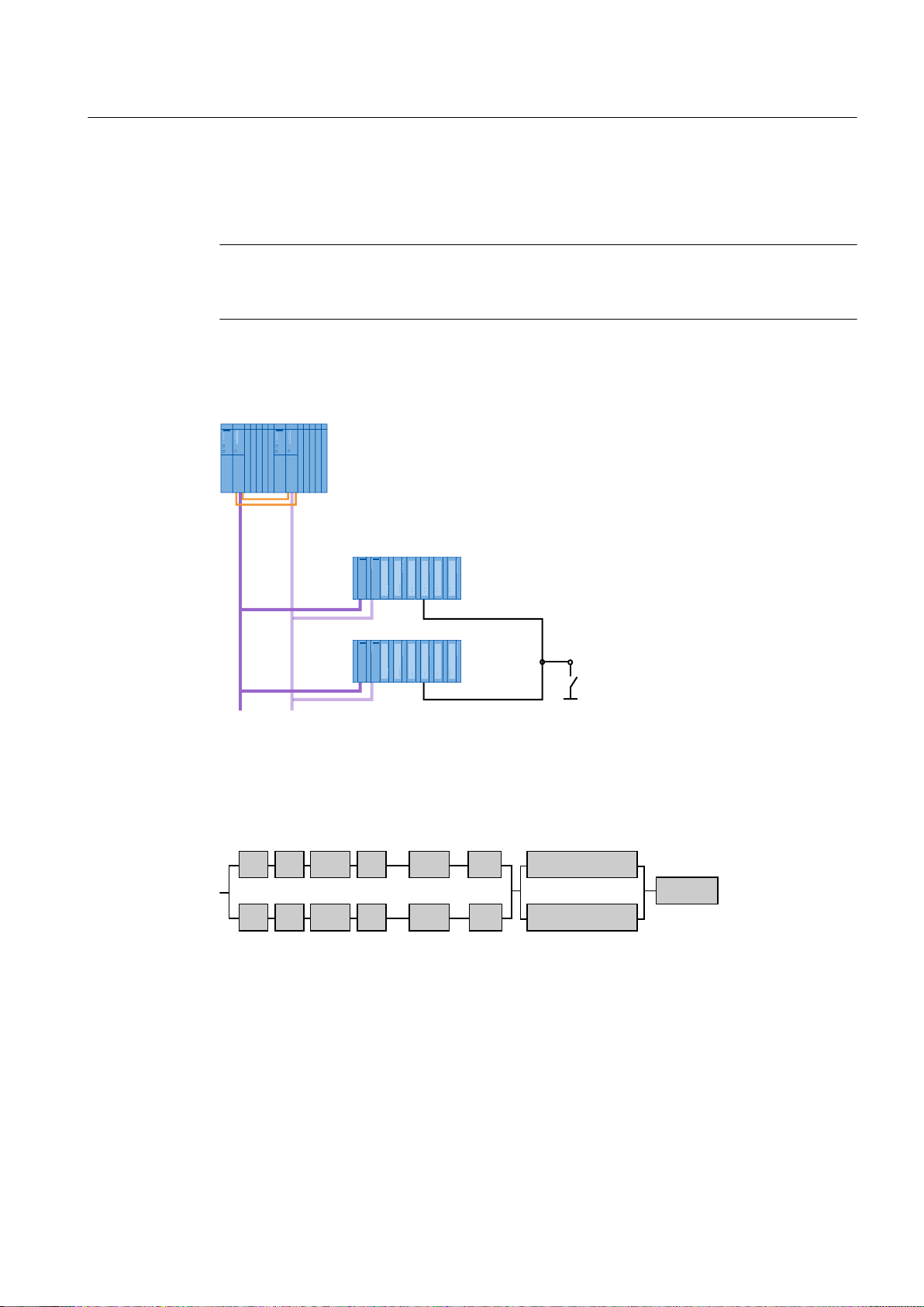
Fault-tolerant Solutions in PCS 7
3.1 Solutions for the I/O
The ET 200M distributed I/O device is connected as redundant DP slave to a fault-tolerant
automation system operating as the DP master via PROFIBUS DP. A redundant configuration
is achieved by installing an additional ET 200M and an additional PROFIBUS DP connection.
Note
Use only active bus modules for the ET 200M in a fault-tolerant system with PCS 7. Active
bus modules enable you to plug and pull modules in runtime.
The following figure illustrates this configuration with ET 200M. Signals from redundant sensors
can be registered.
Availability
The block diagram shows an example configuration with ET 200M without a fault.
If a fault occurs in a maximum of one signal path per redundancy node (e.g. bus line
(bus = PROFIBUS DP) in the first redundancy node and an input module (SM) in the second
redundancy node), the overall system remains operable. The connected device continues to
supply data to the central device, which remains available. If any other component in the
redundancy chain fails, however, the complete system will fail.
Fault-tolerant Process Control Systems (V8.0)
Function Manual, 03/2012, A5E02779471-02 29
Page 30

+6\VWHP
60LQ(70
,,
60LQ(70
,
6HQVRU
%XV
%XV
(70
&38,0
&38
&3
&3
,0
&3
&336
36
Fault-tolerant Solutions in PCS 7
3.1 Solutions for the I/O
Installation rules
The configuration always has to be symmetrical when using redundant I/O. Follow these
installation rules:
● Both subsystems of the S7 400H must be configured identically. The same modules are
located at the same slots.
Example: CPU and CPs are located in both subsystems at the same slot.
● The communication paths and interfaces must be configured the same way in both
subsystems.
Example: The PROFIBUS cables in both subsystems are connected to the same
PROFIBUS DP interface of the CPU 41x-4H.
● Redundant modules are always the same (order number, firmware version)
Configuration rules
● A DP slave must have the same PROFIBUS address in the mutually redundant DP master
systems.
Additional information
● Section "Redundant interface modules in distributed I/O (Page 32)"
● Section "Redundant I/O modules (Page 33)"
● Manual
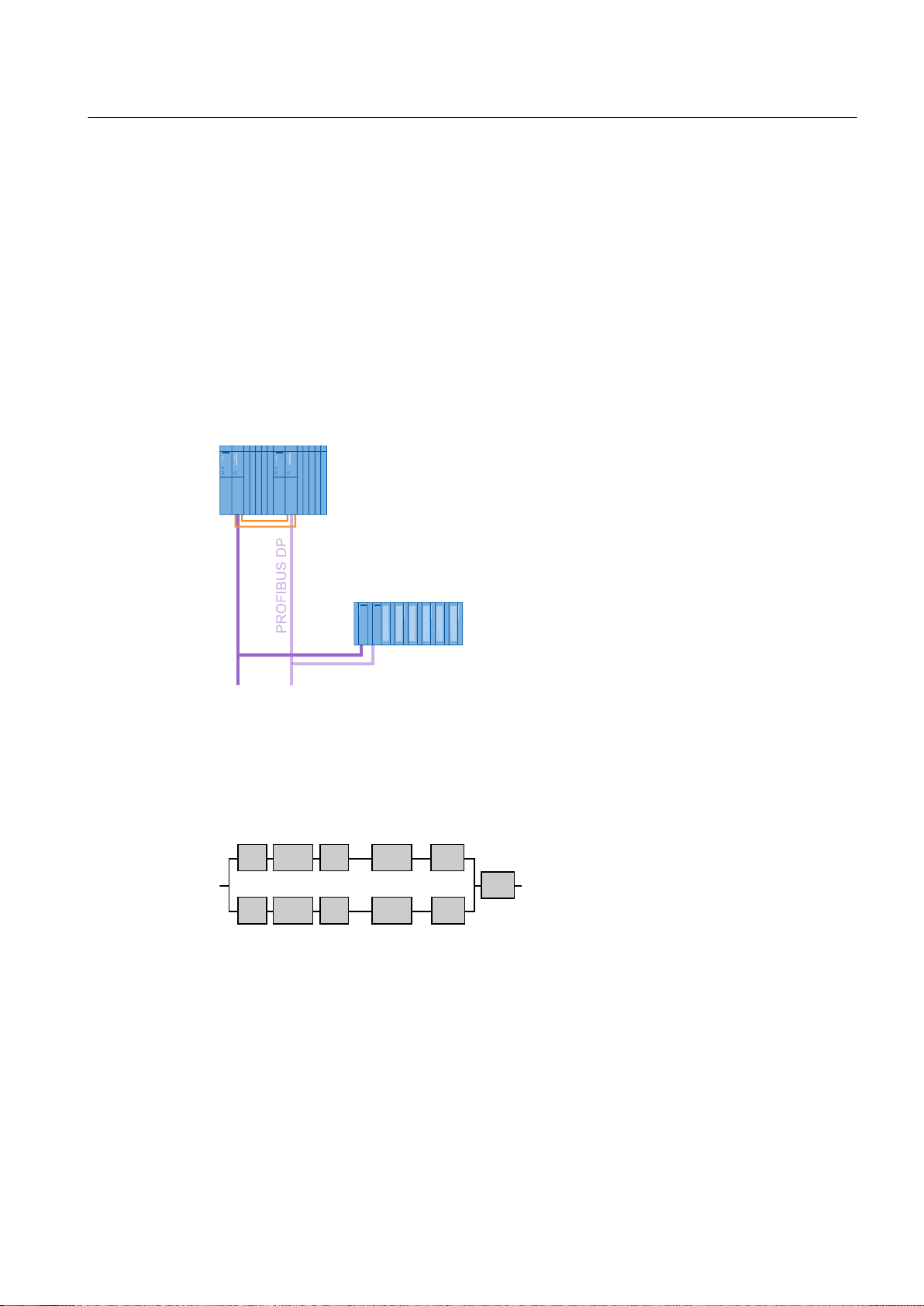
3.1.2 Switched I/O
Switched I/O
Switched I/O describes the situation when there is only one I/O module (SM) for processing a
process signal. The communication path to the I/O (station) is redundant. In the event that a
communication path fails, the distributed I/O (station) switches to the functioning
communication path. The non-redundant I/O modules of the distributed I/O can be addressed
via the redundant interface module (DP slave) of both central modules (CPU) of a fault-tolerant
system.
Automation System S7-400H; Fault-tolerant Systems
Fault-tolerant Process Control Systems (V8.0)
30 Function Manual, 03/2012, A5E02779471-02
Page 31
Configuration
(70VLQJOHFKDQQHO
VZLWFKHG,2FRPSULVLQJ
352),%86'3
[,0
6+
(70
&38,0
&38
&3
&3
,0
&3
&3
60
+6\VWHP
%XV
%XV
Fault-tolerant Solutions in PCS 7
3.1 Solutions for the I/O
A switched I/O can be set up in PCS 7 with the following distributed I/O devices:
● ET 200M
For this setup, you require an ET 200M with active backplane bus modules and a redundant
IM 153-2 interface module.
● ET 200iSP
For this setup, you require an ET 200iSP and a redundant IM 152-1 interface module.
Each subsystem of the S7-400H is connected to one of the two PROFIBUS DP interfaces of
the interface module via a DP master interface.
The following figure illustrates this configuration for the ET 200M.
Availability
The block diagram shows the availability of the configuration illustrated above. When both
systems are operating without fault, the block diagram appears as follows:
The following figure shows how one component may fail without this affecting the operation of
the complete system.
Fault-tolerant Process Control Systems (V8.0)
Function Manual, 03/2012, A5E02779471-02 31
Page 32

(70
&38,0
&38
&3
&3
,0
&3
&3
60
+6\VWHP
%XV
%XV
Fault-tolerant Solutions in PCS 7
3.1 Solutions for the I/O
The system remains available even when one component in part of a line of the redundancy
node fails. There is only one I/O module and therefore no corresponding redundancy node. It
is the weakest link in the complete system's chain.
Installation rules
The configuration always has to be symmetrical when using switched I/O. Follow these
installation rules:
● CPU 41x-xH and additional DP masters must be located in the same slots in each
subsystem (for example, in slot 4 of both subsystems).
● The PROFIBUS cables in both subsystems must be connected to the same interface (for
example, to the PROFIBUS DP interfaces of the two CPU 41x-xH).
Configuration rules
● A DP slave must have the same PROFIBUS address in the mutually redundant DP master
systems.
Additional information
● Section "Redundant interface modules (Page 32)"
● Manual
Automation System S7-400H; Fault-tolerant Systems
3.1.3 Components in the distributed I/O
3.1.3.1 Redundant interface modules in distributed I/O
Redundant interface modules
By using two interface modules in one distributed I/O device, the following can be implemented:
● Setup of a switched distributed I/O
● Setup of a redundant distributed I/O
If the active interface module or the communication path fails via this interface module, the
passive interface module takes over the relevant functions without interruption. The active
interface is indicated by an illuminated "ACT" LED on the respective interface module.
Configuration:
Fault-tolerant Process Control Systems (V8.0)
32 Function Manual, 03/2012, A5E02779471-02
Page 33

The configuration is provided as an example in the section "Redundant I/O (Page 28)".
● ET 200M with redundant IM 153-2
● ET 200iSP with redundant IM 152-1
Additional information
● Section "How to configure the redundant interface module for the I/O device (Page 110)"
● Section "Failure of redundant interface modules (Page 175)"
Fault-tolerant Solutions in PCS 7
3.1 Solutions for the I/O
Two IM 153-2 interface modules are mounted on the active bus module in the distributed
I/O device for redundant operation.
Two IM 152-1 interface modules are mounted on the active TM-IM/IM terminal module in
the distributed I/O device for redundant operation.
Note
The signal modules of the ET 200iSP cannot be used redundantly.
● Manual
● Manual
● Manual
SIMATIC, Distributed I/O Device ET 200M
SIMATIC, Distributed I/O Device ET 200iSP
Automation System S7-400H; Fault-tolerant Systems
3.1.3.2 Redundant I/O modules
Configuring redundant input/output modules
Redundant I/O modules enable you to increase the availability in the I/O area.
The following configurations are possible with redundant I/O modules:
● Redundant input/output modules in redundant distributed I/O
An example of this configuration is shown in the section "Redundant I/O (Page 28)"
● Redundant input/output modules in single-channel switched distributed I/O
An example of this configuration is shown in the section "Switched I/O (Page 30)"
Note
Refer to the interconnection examples for redundant I/O (redundant input/output modules)
in the manual
Automation System S7-400H; Fault-tolerant Systems
.
Redundant operation of S7-300 I/O modules
The following requirements must be met to operate redundant S7-300 I/O modules in the
automation system:
● PCS 7 as of V6.0
● H-CPU as of firmware version V3.1
● Suitable S7-300 I/O modules (documentation:
Fault-tolerant Process Control Systems (V8.0)
Function Manual, 03/2012, A5E02779471-02 33
PCS 7 - Released Modules
)
Page 34

Fault-tolerant Solutions in PCS 7
3.1 Solutions for the I/O
Required software and configuration
You select and configure the redundant modules in HW Config.
● In order for both subsystems of the H system to be able to address redundant input/output
modules, S7 driver blocks from the "Redundant I/O" library and PCS 7 driver blocks from
the
PCS 7 Library
● Modules with the same order number and version number can be paired in redundant
configurations.
You interconnect the signals in the CFC chart. Additional information on this is available in the
section "Configuration of redundant signals (Page 126)".
When the user program is compiled, the required driver blocks are placed, interconnected and
configured automatically.
as of PCS 7 V6.0 are required in addition to the necessary hardware.
Reaction to a channel fault
You can define the passivation characteristics, for example how redundant input/output
modules react to a channel fault (such as broken wire, short-circuit on the signal line). The
reaction to a channel fault depends on the following aspects:
● Module employed
● Configuration
● Version of the PCS 7 library
You will find information on the passivation reaction for individual modules in the
documentation
Additional information
● Section "How to configure redundant I/O modules (Page 112)"
● Section "Failure of redundant I/O modules (Page 175)"
● Section "How to set the failure reaction of the input/output modules on the CPU (Page 95)"
● Manual
● Online help for
– As of PCS 7 V7.1, the potential passivation reaction is automatically detected based on
the configured modules. The passivation reaction is set channel-by-channel.
– Only the module-based passivation reaction can be selected with the Redlib V3.x library.
– You can set the channel-based passivation reaction with the Redlib library as of V4.
PCS 7 - Released Modules
.
Automation System S7-400H; Fault-tolerant Systems
STEP 7
3.1.3.3 Redundant actuators and sensors
Failure detection
Actuators and sensors on the field level can be configured redundantly for PCS 7. Depending
on the I/O module to which the redundant actuators or sensors are connected, failure of an
actuator or sensor can be detected and reported to the process control system as an error. If
Fault-tolerant Process Control Systems (V8.0)
34 Function Manual, 03/2012, A5E02779471-02
Page 35

an actuator/sensor fails, the automation system continues to operate with the intact actuator/
sensor. This ensures that the current status of the process values can be read in or output at
any time.
Note
Refer to the product description of the I/O module you are using to see whether it can detect
and report failures of connected actuators and sensors.
Additional information
Fault-tolerant Solutions in PCS 7
3.2 Solutions for automation systems
● Manual
Automation System S7-400H; Fault-tolerant Systems
3.2 Solutions for automation systems
Introduction
This chapter presents solutions that can be used to increase the availability of an automation
system.
S7-400H fault-tolerant programmable controller
Only a fault-tolerant automation system can ensure an extremely short process safety time,
for example, a switchover time in the milliseconds range. PCS 7 enables you to configure your
process control system with redundancy using the S7-400H fault-tolerant programmable
controller.
Functionality
The S7-400H programmable controller and all the other components in the PCS 7 environment
are tuned to one another.
With this solution, a second backup CPU, which is event-synchronized to the master CPU,
performs the same processing tasks of the user program as the master. If the active master
CPU fails, the standby CPU continues processing the user program without delay. This type
of standby is referred to as "Hot standby".
There are always two CPUs and two power supplies in an S7-400H. The communications
processors and I/O modules are expansion modules.
Fault-tolerant Process Control Systems (V8.0)
Function Manual, 03/2012, A5E02779471-02 35
Page 36

36
&38
5DFNVSDWLDOO\VHSDUDWHG6+
EDVLFV\VWHPVXEV\VWHP
V\QF
PRGXOHV
ILEHURSWLF
FDEOHV
6\QFKURQL]DWLRQOLQHV
Fault-tolerant Solutions in PCS 7
3.2 Solutions for automation systems
3.2.1 S7-400H hardware components
Hardware components
The following hardware components are available for the configuration of the fault-tolerant
automation system.
Hardware components
Mounting rack UR2-H
Mounting rack UR2
Mounting rack UR1
Central processing unit CPU 412-3H ... -5H PN/DP
Central processing unit CPU 414-4H ... 5H PN/DP
Central processing unit CPU 416- 5H PN/DP
Central processing unit CPU 417-4H... 5H PN/DP
Synchronization modules
Synchronization cable (up to 10 km)
Communications processor CP 443-5 Extended
Communications processor CP 443-1
Setup
36 Function Manual, 03/2012, A5E02779471-02
Fault-tolerant Process Control Systems (V8.0)
Page 37

Mounting racks
The following three racks are available for installing the S7-400H. Normally, the UR2-H rack
is used.
Module type Size Special feature
UR2-H 2 x 9 slots Installation of two separate subsystems each with nine
UR1 1 x 18 slots Two racks are required for an S7-400H .
UR2 1 x 9 slots Two racks are required for an S7-400H .
Central processing units
There are two CPUs in an H-system. The two CPUs are connected to one another using
synchronization modules and fiber-optic cables.
Fault-tolerant Solutions in PCS 7
3.2 Solutions for automation systems
modules. The two subsystems are electrically isolated
(not mechanically).
It is not possible to replace a rack in runtime.
You can replace a rack in runtime.
You can replace a rack in runtime.
Power supply
A separate power supply module from the standard S7-400 series is needed for each
subsystem of the S7-400H. Two power supply modules can be used in each subsystem to
increase the availability of the fault-tolerant system. In this case, use the following power supply
modules that can be used for redundancy.
Power supply modules for 24 VDC as well as for 120/230 VAC nominal input voltages with
output currents of 10 and 20 A.
Synchronization modules
Synchronization modules are used to link the two central processing units. They are installed
in the central processing units and interconnected with fiber-optic cable. Two synchronization
modules are installed in each CPU.
Set the rack number for the H CPU as of firmware version V4.X directly on the CPU. The
synchronization modules can be replaced in runtime.
The same rack number must be set at all synchronization modules up to firmware V3.x.
Fiber-optic cables for synchronization
The fiber-optic cables are connected to the synchronization modules and form the physical
connection (redundancy link) between the two automation stations. The synchronization
cables must not be cross-connected.
In addition to the standard lengths of 1 m, 2 m, and 10 m, custom-made synchronization cables
are available in lengths up to 10 km.
Fault-tolerant Process Control Systems (V8.0)
Function Manual, 03/2012, A5E02779471-02 37
Page 38

Fault-tolerant Solutions in PCS 7
3.2 Solutions for automation systems
Transmission medium
The suitable physical transmission medium depends on the range, resistance to interference
and the transmission rate.
● Industrial Ethernet using fiber-optic cables or triaxial or twisted-pair copper lines can be
used for communication between the automation system and the OS servers.
● PROFIBUS DP with electrical or optical components is used for communication from the
automation system to the distributed I/O devices.
The transmission media and communication processors can be configured redundantly. If the
active communication component (CP, bus) fails, the communication automatically continues
through the redundant connection.
Only Industrial Ethernet with ISO protocol can be used as the plant bus for a fault-tolerant
system. The communication modules must also support the ISO protocol.
Equipping the rack
The hardware setup in the automation system and the configuration in HW Config must match:
● Rack (9 or 18 slots for redundant and, in some cases, remote configuration)
● Power supply modules (in some cases redundant configuration)
● H CPU with sync modules in slots "IF1" and "IF2"
● Communications processors (CP 443-1, CP 443-5 Extended)
Configuration
A pre-existing network can be used for fault-tolerant communication between non-redundant
SIMATIC stations and (redundant) SIMATIC H stations. You set the parameters of the faulttolerant S7 connections in NetPro.
The required communication blocks for data transmission (measured values, binary values,
interlocks) are available in the
transmission mechanism which, for example, may be secured or unsecured.
Additional information
● Section " How to add a SIMATIC H station to your project (Page 90) "
● Section " How to insert synchronization modules into the H CPU (Page 91) "
● Section " How to configure redundant communication processors (Page 93) "
● Section " Time synchronization (Page 88) "
● Manual
PCS 7 Library
. The communication blocks differ in their
Automation System S7-400H; Fault-tolerant Systems
Fault-tolerant Process Control Systems (V8.0)
38 Function Manual, 03/2012, A5E02779471-02
Page 39

3.2.2 How the SIMATIC S7-400H AS operates
Active redundancy
The automation system consists of two redundantly configured subsystems, which are
synchronized through fiber-optic cables.
The two subsystems form a fault-tolerant automation system that operates with a dual-channel
design according to the principle of active redundancy. Active redundancy, often referred to
as functional redundancy, means that all redundant components are in continual operation
and simultaneously involved in the acquisition of process data. The control task is the
responsibility of the redundancy partner that is active at any given time. The user programs
loaded in both CPUs are fully identical and are run synchronously by both CPUs.
If the active CPU fails, the automation system automatically switches to the redundant CPU
(see section "S7-400H hardware components (Page 36)" and Documentation
System, SIMATIC PCS 7, Released Modules
process because it is bumpless.
Additional information
Fault-tolerant Solutions in PCS 7
3.3 Solutions for communication
Process Control
). The failover has no effect on the ongoing
● Section "Failure of the master CPU (Page 177)"
● Section "Failure of a fiber-optic cable (Page 178)"
● Manual
Automation System S7-400H; Fault-tolerant Systems
3.3 Solutions for communication
Introduction
In this section, you will learn about the redundancy concepts for the various levels of the
process control system.
Requirements for communication systems
The availability of a process control system is not only determined by the automation system,
the environment also plays a considerable role. This includes not only the operator control and
monitoring components but also a high-performance communication system that connects the
management level to the process level and the process level to the field level.
Distributed control systems are also needed in the manufacturing and processing automation.
Complex control tasks are broken down into smaller, simpler steps with distributed form. The
demand for communication between distributed systems increases.
High-performance, comprehensive communication system is needed to fulfill this demand. The
communication connections between the systems involved should be redundant.
Local networks (LAN) form the basis of the communication system. The following are options
that can be implemented based on the specific system requirements:
Fault-tolerant Process Control Systems (V8.0)
Function Manual, 03/2012, A5E02779471-02 39
Page 40

'RXEOHFRPPXQLFDWLRQOLQHV
&RQWUROOD\HU
7HUPLQDOEXV
3&1HWZRUN,QG(WKHUQHW
3URFHVVOD\HU
6\VWHPEXV
)LHOGOD\HU
)LHOGEXV
,QGXVWULDO(WKHUQHW
352),%86'3
Fault-tolerant Solutions in PCS 7
3.3 Solutions for communication
● Electrical
● Optical
● Electrical/optical combination
The communication connections are grouped in three areas:
● Terminal bus
● Plant bus
● Fieldbus
In PCS 7, we recommend that the bus systems are set up in a ring structure. The ring structure
makes the bus "fault-tolerant", since it can compensate for the failure of a bus line.
Redundant communication connections
Redundant communication connections can be formed on all levels of the process control
system.
When a communication error occurs, communication automatically switches over from the
active connection to the backup connection. Both connections use the same media and
protocols. The failover has no effect on the user program running in the CPU.
Overview of the redundant and fault-tolerant bus systems
40 Function Manual, 03/2012, A5E02779471-02
In PCS 7 systems, you can configure fully redundant bus systems with redundant components
for the following bus systems:
● Redundant, fault-tolerant terminal bus (Page 49)
● Redundant, fault-tolerant plant bus (Page 59)
● Redundant PROFIBUS DP (Page 62)
Fault-tolerant Process Control Systems (V8.0)
Page 41

Bus systems set up as a ring are fault-tolerant. In ring structures, the signal path remains intact
even if there is a disconnection on the transmission cable at any point in the ring (for example
due to a wire break). The availability is ensured by ring redundancy.
This fault-tolerance is used in the following bus systems:
● Fault-tolerant terminal bus (Page 47)
● Fault-tolerant plant bus (Page 57)
● Fault-tolerant PROFIBUS PA (Page 68)
● Fault-tolerant PROFINET bus (Page 64)
The following sections describe the basics of these communications solutions.
3.3.1 Network components
Introduction
Local networks (LAN) form the basis of the communication system. The following are options
that can be implemented based on the specific system requirements:
Fault-tolerant Solutions in PCS 7
3.3 Solutions for communication
● Electrical
● Optical
● Optical/electrical (mixed operation)
Overview of the network components
You can set up bus systems with the following link and switch modules of SIMATIC NET.
Note
OSM and OLM mixed operation is not permitted.
Fault-tolerant Process Control Systems (V8.0)
Function Manual, 03/2012, A5E02779471-02 41
Page 42

Fault-tolerant Solutions in PCS 7
3.3 Solutions for communication
Network component Bus system Application
Switch (from the
SCALANCE series)
SCALANCE X204 RNA Terminal bus Connecting a singular infrastructure component
ESM (Electrical Switch
Module)
OSM (Optical Switch
Module)
Switch (from the
SCALANCE series)
OLM (Optical Link Module) Fieldbus
Terminal bus
Plant bus
Terminal bus
Plant bus
Terminal bus
Plant bus
Fieldbus
● PROFINET
● PROFIBUS DP
Type-specific use in network setup
Selected SCALANCE X components enable the
following:
● Transmission rates up to 1 Gbps
● Media converter (electrical/optical
bidirectional)
● Function as redundancy manager
(configuration of ring redundancy)
● Function as standby manager (redundant
linking of networks)
Depending on the type, either optical or electrical
connections are used.
to the redundant terminal bus. For example:
● SICLOCK TC400
● Domain controller
● File server
2 ports for the infrastructure components
Setup of electrical bus systems
(suitable as redundancy manager)
The connection to the ESMs is electrical.
Setup of optical bus systems
An optical ring must be configured with at least
two optical switch modules.
(suitable as redundancy manager)
The connection to the OSMs is electrical or
optical.
● Fieldbus as fault-tolerant PROFINET ring
Setup of optical transmission paths
Configuration variants:
● DP master (electrical) > OLM > FO > OLM >
interface module (electrical connection)
● DP master (electrical) > OLM > FO >
interface module (optical connection)
Fault-tolerant Process Control Systems (V8.0)
42 Function Manual, 03/2012, A5E02779471-02
Page 43
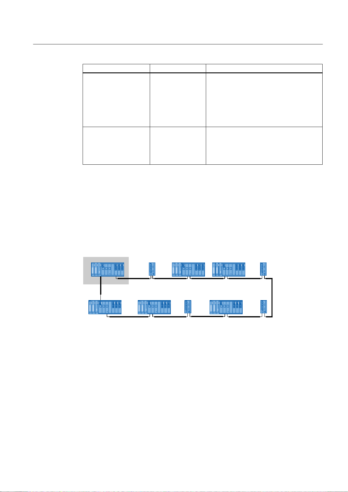
Network component Bus system Application
AFD (Automatic Field
Distributor)
AFDiS
AFS (Automatic Field
Splitter)
Redundancy manager
Certain network components in the SIMATIC NET product range support the redundancy
manager function.
Fieldbus
● PROFIBUS PA
● FOUNDATION
Fieldbus
Fieldbus
● PROFIBUS PA
● FOUNDATION
Fieldbus
Fault-tolerant Solutions in PCS 7
3.3 Solutions for communication
Connection of field devices via ring redundancy
● Maximum of 31 fieldbus components on one
bus
● Maximum of 8 AFD/ADFiS on a redundant
fieldbus coupler
● Maximum of 4 field devices per AFD
● Maximum of 6 field devices per AFDiS
Connection of field devices via coupler
redundancy
● 1 AFS on a redundant fieldbus coupler
● Maximum of 31 fieldbus components on the
AFS
Standby manager
This function enables the configuration of ring redundancy. Network components operating as
the redundancy manager can ensure that the bus connections remain undisturbed if there is
a fault on a bus line (such as a cable break).
Example of a ring structure with SCALANCE X400 and X200
The SCALANCE X414-3E as the redundancy manager has a gray background in the figure.
Switches and data links (network cable) connect the redundant networks. Redundant coupling
of networks is only possible if two devices (switches) within a network segment support the
standby manager function. Certain network components from the SIMATIC NET product range
support this function.
Within a network segment, both devices are configured for the standby manager function. The
two devices exchange data frames via the bus line and thereby synchronize their operating
status. One network component becomes the standby manager (master) and the other standby
manager (slave).
When operation is error-free, the data link running between the redundant networks is active
for the standby manager (master). If this data link fails (e.g., due to a defective device or cable
break), the standby manager (slave) activates its data link while the fault remains pending.
Example of a ring structure with SCALANCE X
Fault-tolerant Process Control Systems (V8.0)
Function Manual, 03/2012, A5E02779471-02 43
Page 44

5HGXQGDQF\PDQDJHU
%XV%XV
5HGXQGDQF\PDQDJHU
6WDQGE\PDQDJHUVODYH
6WDQGE\PDQDJHUPDVWHU
Fault-tolerant Solutions in PCS 7
3.3 Solutions for communication
SCALANCE X switches for setting up redundant networks
You can find additional information on SCALANCE X switches approved for PCS 7 in the
Process Control System PCS 7; Released Modules
the necessary functions available to set up the relevant redundant network:
● Redundancy manager
● Standby manager
● Parallel Redundancy Protokoll
documentation. The switches must have
PC stations on networks
The PC stations are connected to the networks via communication modules and network
cables.
The communication modules occupy a slot in the PC or programming device (PG). A variety
of communication modules can be used, depending on the requirements. You can find
information on this in the following sections:
● Section "Connecting PC stations to the terminal bus (Page 46)"
● Section "Connecting PC stations to the plant bus (Page 56)"
Additional information
● Documentation
● Documentation
● Manual
● Manual
● Manual
● Manual
● Operating Instructions
● Operating Instructions
Process Control System PCS 7; PCS 7 Readme
Process Control System PCS 7; Released modules
SIMATIC Net Twisted Pair and Fiber-Optic Networks
SIMATIC NET; Industrial Ethernet OSM/ESM
SIMATIC Net PROFIBUS Networks
SIMATIC; Communication with SIMATIC
SIMATIC NET; Industrial Ethernet Switches SCALANCE X-200
SIMATIC NET; Industrial Ethernet Switches SCALANCE X-300
● Operating Instructions
● Configuration Manual
SIMATIC NET; Industrial Ethernet Switches SCALANCE X-400
SIMATIC NET; Industrial Ethernet Switches; SCALANCE X-300;
SCALANCE X-400
Fault-tolerant Process Control Systems (V8.0)
44 Function Manual, 03/2012, A5E02779471-02
Page 45

3.3.2 Media Redundancy Protocol
Use of media redundancy protocol
Note
HSR (High Speed Redundancy) and MRP (Media Redundancy Protocol)
The X200 IRT switches cannot serve as redundancy manager and standby manager at the
same time.
Standby managers can only be operated with the media redundancy protocol, High Speed
Redundancy (HSR) . Standby redundancy and media redundancy protocol do not work
together.
HSR MRP
Separate terminal
and plant bus
Common terminal
and plant bus
PROFINET -
fieldbus ring
X -
X -
Fault-tolerant Solutions in PCS 7
3.3 Solutions for communication
- The following Industrial Ethernet switches support MRP:
● SCALANCE X-200 from firmware version V4.0
● SCALANCE X-200 IRT from firmware version V4.0
● SCALANCE X-300 from firmware version V3.0
● SCALANCE X-400 from firmware version V3.0
HSR
HSR is used for the redundant connection to the terminal and plant bus.
Ring redundancy and redundant connection of rings are possible by means of configuration
of the following functions:
● Redundancy manager
● Standby manager
MRP
All devices must support MRP to permit the redundant connection in a fieldbus ring based on
PROFINET .
Additional information
Further information regarding HSR and MRP may be found in the documentation for the
Industrial Ethernet Switches.
Fault-tolerant Process Control Systems (V8.0)
Function Manual, 03/2012, A5E02779471-02 45
Page 46

Fault-tolerant Solutions in PCS 7
3.3 Solutions for communication
3.3.3 Solutions for the terminal bus
3.3.3.1 Connecting PC stations to the terminal bus
You can connect the following PC stations to industrial Ethernet via communication modules
(network adapters or communications processors):
● Operator stations
● BATCH stations
● Route Control stations
● Engineering stations
The communication modules occupy a slot in the PC or programming device (PG). Depending
on the requirement
Communication modules for connection to the terminal bus
● Standard communication modules (for example, Intel® Gigabit CT Desktop Adapter)
Components
● Variants for the redundant connection of the PC station to a terminal bus:
– Parallel Redundancy Protocol
– INTEL TEAM mode
Check, using the product documentation, whether the communication modules are suitable
for the implementation of the concept in question for the terminal bus.
The following network adapters are approved in PCS 7.
● PCIe network adapters:
– Intel® PRO/1000 PT Server Adapter
– (Intel® Gigabit CT Desktop Adapter (Intel® PRO/1000 PT Desktop Adapter is permitted)
● integrated network adapter (from bundle PC with Windows 7/Server 2008 R2)
– INTEL ... (LM-Adapter)
– INTEL ... (L-Adapter)
● PCI network adapters (for Windows XP/2003 operating systems only)
– Intel PRO/1000 MT Server-Adapter
– Intel PRO/1000 GT Desktop-Adapter
Additional information
● Documentation
● Documentation
46 Function Manual, 03/2012, A5E02779471-02
Process Control System PCS 7; Released modules
Process Control System PCS 7; PCS 7 Readme
Fault-tolerant Process Control Systems (V8.0)
Page 47

3.3.3.2 Fault-tolerant terminal bus
The terminal bus connects the servers (OS servers, BATCH servers, Route Control servers)
with the clients of the process control system (OS clients, BATCH clients, Route Control
clients).
fault-tolerant terminal bus can be set up in a ring structure with network components of
SIMATIC NET. The network components enables unrestricted operation of the terminal bus.
For example, a broken cable in the connection between the modules is tolerated and
communication remains uninterrupted.
If the terminal bus experiences problems, no process data are sent from the servers to the
clients.
Fault-tolerant communication solutions
The following solutions are available to guard against failure of the terminal bus:
● Ring structure in an electrical network. The connection to the switches is electrical.
● Ring structure in an optical network with switches and FO cables. The connection to the
switches is electrical or optical.
Fault-tolerant Solutions in PCS 7
3.3 Solutions for communication
Configuration
● Ring structure in a combined network with optical and electrical switches and FO cables.
The connection to the switches is electrical.
● Ring structures as optical, electrical and combined networks with transfer rates up to 1
Gbps based on the modular switches
In the following figure, the terminal bus is shown as a ring with switches as an example. The
OS servers are connected to the switches in a distributed pattern in order to take optimal
advantage of the switch functionality. The probability of OS server failure due to the failure of
a switch and the bus load are thereby reduced.
The log data of the control process is secured and continuously available if you use two OS
clients each equipped with a line printer for printing the message sequence reports.
Note
If a switch fails, the connection to the associated nodes will also fail. Therefore, redundant
servers must not be connected to the same switch.
Fault-tolerant Process Control Systems (V8.0)
Function Manual, 03/2012, A5E02779471-02 47
Page 48
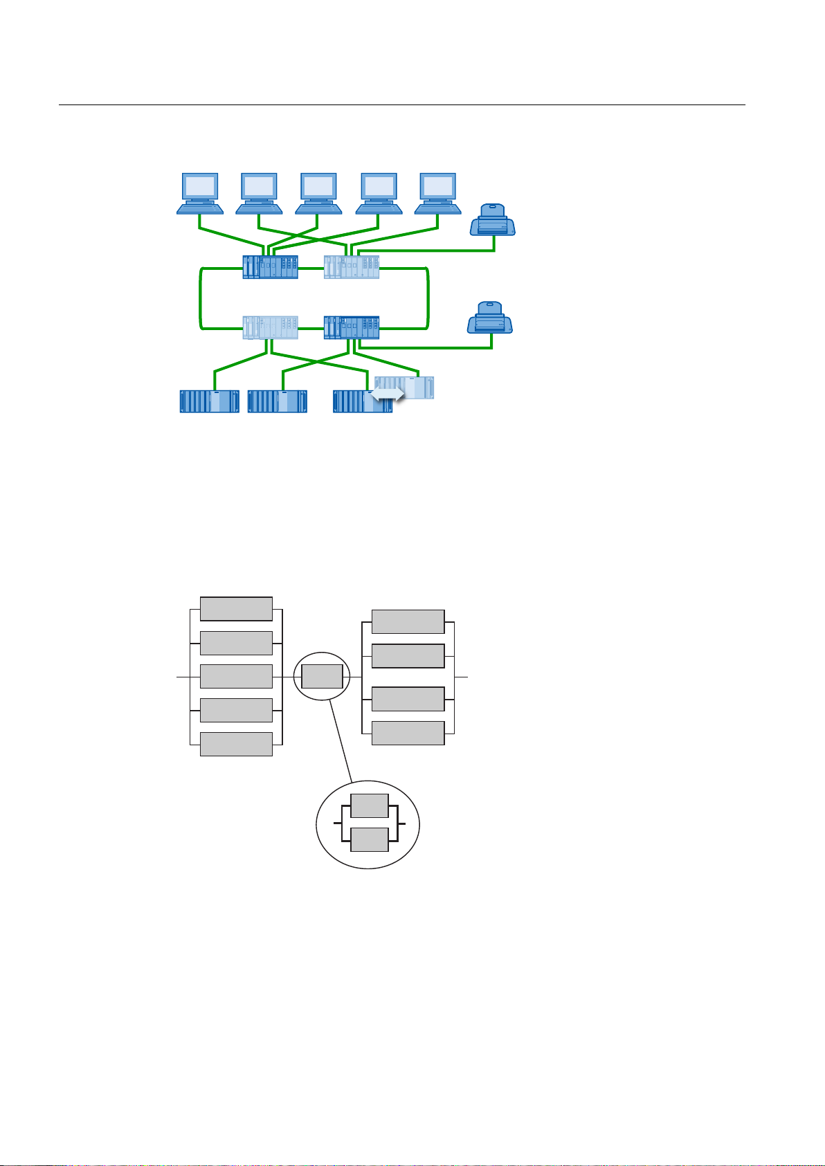
26VHUYHU
26FOLHQWV
UHGXQGDQW26VHUYHUSDLU
3ULQWHUIRUPHVVDJH
VHTXHQFHUHSRUW
3ULQWHU
,QGXVWULDO(WKHUQHW
)DXOWWROHUDQWWHUPLQDOEXV
%XV
%XV
26VHUYHU
26FOLHQW
%XV
26FOLHQW
26FOLHQW
26FOLHQW
26FOLHQW
26VHUYHU
26VHUYHU
26VHUYHU
Fault-tolerant Solutions in PCS 7
3.3 Solutions for communication
Availability
If there is a fault in a ring line, the communication between clients and servers via the switches
remains unaffected. However, if one of the switches fails, the link between the connected OS
servers and the OS clients is interrupted. To increase the fault-tolerance even more, however,
the redundant ring described in the following section can be used.
Additional information
● Manual
SIMATIC Net Twisted Pair and Fiber-Optic Networks
● Operating Instructions
● Operating Instructions
SIMATIC NET; Industrial Ethernet Switches SCALANCE X-400
SIMATIC NET; Industrial Ethernet Switches SCALANCE X-300
Fault-tolerant Process Control Systems (V8.0)
48 Function Manual, 03/2012, A5E02779471-02
Page 49

Fault-tolerant Solutions in PCS 7
3.3 Solutions for communication
● Operating Instructions
● Manual
SIMATIC NET; Industrial Ethernet OSM/ESM
SIMATIC NET; Industrial Ethernet Switches SCALANCE X-200
3.3.3.3 Redundant, fault-tolerant terminal bus
Functionality
The terminal bus connects the servers (OS servers, BATCH servers, Route Control servers)
etc. with the clients of the process control system (OS clients, BATCH clients, Route Control
clients).
The following solutions for a redundant, fault-tolerant terminal bus are offered as of PCS 7
V8.0:
● Redundant, fault-tolerant terminal bus based on the Parallel Redundancy Protocol (PRP)
(Page 50)
Separate double ring with PRP; solution in accordance with IEC 62439-3)
● Redundant, fault-tolerant terminal bus based on the INTEL TEAM mode (Page 52)
Coupled double ring based on redundant coupling of network segments - formed by two
identical coupled terminal bus rings
Redundant components
The following components are configured redundantly:
● Electrical or optical network with Ethernet switches
● Switches, fiber optic cables and electrical connections
● Ring structures based on switches from the SCALANCE series.
You can find additional information on the switches used with PCS 7 in the section "Network
components (Page 41)".
Additional information
● Section "How to configure the redundant terminal bus on the basis of the Parallel
● Section "How to configure the redundant terminal bus on the basis of the INTEL TEAM
● Documentation
● Manual
● Operating Instructions
● Configuration manual
● Operating Instructions
● Operating instructions
Redundancy Protocol (Page 97)"
mode (Page 97)"
PCS 7 Released Modules
SIMATIC Net Twisted Pair and Fiber-Optic Networks
SIMATIC NET; Industrial Ethernet Switches SCALANCE X-400
SIMATIC NET; Industrial Ethernet Switches SCALANCE X-400
SIMATIC NET; Industrial Ethernet Switches SCALANCE X-200
SIMATIC NET; Industrial Ethernet; "SCLANCE X204RNA,
SCALANCE X204RNA EEC"
Fault-tolerant Process Control Systems (V8.0)
Function Manual, 03/2012, A5E02779471-02 49
Page 50

%XV%XV
5HGXQGDQF\PDQDJHU
&OLHQW26&OLHQW26
6HUYHUB0
6HUYHUB6
1HWZRUNDGDSWHU
1HWZRUNDGDSWHU
6&$/$1&(;51$
5HGXQGDQF\PDQDJHU
Fault-tolerant Solutions in PCS 7
3.3 Solutions for communication
● Operating instructions
SIMATIC NET; PG/PC - Industrial Ethernet; SOFTNET‑IE RNA
● Readme for SOFTNET IE RNA
3.3.3.4 Redundant, fault-tolerant terminal bus based on the Parallel Redundancy Protocol (PRP)
The section below describes the basic structure of a redundant fault-tolerant terminal bus using
the SIMATIC NET SOFTNET-IE RNA software. This software is based on the Parallel
Redundancy Protocol (PRP) as specified in IEC 62439-3.
Each PC station is connected to 2 separate redundant networks with one network adapter
each. The communications processes on the redundantly connected PC stations are organized
by the SIMATIC NET SOFTNET-IE RNA software.
Install SIMATIC NET SOFTNET-IE RNA on every redundantly connected PC station.
Information on this topic can be found in the
SOFTNET-IE RNA
operating instructions.
The following diagram illustrates a sample configuration based on the SIMATIC NET
SOFTNET-IE RNA software:
SIMATIC NET; PG/PC - Industrial Ethernet;
Quantity structure for the operator station
50 Function Manual, 03/2012, A5E02779471-02
You can find information about this in the
quantity structures
documentation.
Process Control System PCS 7; Licenses and
Fault-tolerant Process Control Systems (V8.0)
Page 51

26VHUYHU
26VHUYHU
26FOLHQW
26FOLHQW
1HWZRUNDGDSWHU
1HWZRUNDGDSWHU
1HWZRUNDGDSWHU
%XV1HWZRUNDGDSWHU
1HWZRUNDGDSWHU
%XV
%XV
%XV
%XV
%XV
1HWZRUNDGDSWHU
1HWZRUNDGDSWHU
1HWZRUNDGDSWHU
Fault-tolerant Solutions in PCS 7
3.3 Solutions for communication
Redundant, fault-tolerant terminal bus with SIMATIC NET SOFTNET-IE RNA
All protocols among the redundantly connected components are automatically duplicated, sent
and distributed in the mutually redundant networks. The receiver uses the first incoming frame
with the same information from the redundant networks.
Advantages:
● Easy administration
● A fault on one bus has no effect on the redundant bus
Components
SCALANCE series switches are used to connect the components. Recommended switches
that support the Parallel Redundancy Protocol may be found in the
PCS 7; Released modules
documentation.
Availability - redundant fault-tolerant terminal bus
The entire transmission route can be configured redundantly. A transmission route remains
operational for communication on the terminal bus if any of the network components fails.
Process Control System
Connecting non-redundant networks and components
Fault-tolerant Process Control Systems (V8.0)
Function Manual, 03/2012, A5E02779471-02 51
An integrated solution of network components and protection devices can be implemented for
a substation or process application using PRP-compatible SCALANCE X products. Connect
components having only one network connection to the redundant, fault-tolerant terminal bus
Page 52

Fault-tolerant Solutions in PCS 7
3.3 Solutions for communication
using the SCALANCE X204RNA . Select this connection for infrastructure components, for
example:
● Master system clock (from SICLOCK TC400)
● Domain controllers (DCs), DNS, WINS, DHCP, WSUS
● WLAN access point
● File server
Requirements
● Per SCALANCE X204RNA, a maximum of two non-redundant networks and components
with only one network connection
● Two separate, redundant terminal bus networks
● Maximum distance to network node (component/switch) = 10 m
Additional information
● Operating instructions
● Readme file for the "SIMATIC NET SOFTNET-IE RNA" software
● Section "How to configure the redundant terminal bus on the basis of the Parallel
Redundancy Protocol (Page 97)"
● Operating Instructions
SIMATIC NET; PG/PC - Industrial Ethernet; SOFTNET-IE RNA
SIMATIC NET; Industrial Ethernet; "SCALANCE X204RNA,
SCALANCE X204RNA EEC
● You can find information on the available operating systems in the
PCS 7 Readme
3.3.3.5 Redundant, fault-tolerant terminal bus based on the INTEL TEAM mode
The following section describes the basic structure of a redundant, fault-tolerant terminal bus
using network adapters working in "INTEL Team" mode.
The following figure shows this configuration.
file.
Fault-tolerant Process Control Systems (V8.0)
52 Function Manual, 03/2012, A5E02779471-02
Page 53

5HGXQGDQF\PDQDJHU
%XV%XV
5HGXQGDQF\PDQDJHU
6WDQGE\PDQDJHUVODYH
6WDQGE\PDQDJHUPDVWHU
&OLHQW26&OLHQW26
6HUYHUB06HUYHUB6
6HUYHUDGDSWHUPDVWHU
HJ,QWHOp35237VHUYHUDGDSWHU
'HVNWRSDGDSWHUVWDQGE\
HJ,QWHOp*LJDELW&7GHVNWRSDGDSWHU
Fault-tolerant Solutions in PCS 7
3.3 Solutions for communication
Redundant, fault-tolerant terminal bus with redundant linking of network segments (rings)
Note
Redundant linking of network segments
The redundant linking of two network segments is only possible when the linking switches
are capable of acting as standby manager.
Example:
● Linking with SCALANCE X414-3E
● For Gigabit Ethernet: Linking with SCALANCE X408-2
One pair of redundancy-capable network adapters is used for each PC station in each server
to be connected to the terminal bus (for example, OS server, BATCH server, domain
controller), (see section "Connecting PC stations to the terminal bus (Page 46)"). Teamcapable network adapters are required for this configuration. They work in " INTEL Team
mode" with only one logical network address. Each network adapter is connected to one of
the redundant terminal bus rings (bus1/bus2). The link between the redundant network
segments (rings) is implemented using two switches in each network.
Fault-tolerant Process Control Systems (V8.0)
Function Manual, 03/2012, A5E02779471-02 53
Page 54

Fault-tolerant Solutions in PCS 7
3.3 Solutions for communication
Components
The following switches can be used:
● SCALANCE series of switches
Modules for optical or electrical connection are used for the connection.
● OSM (optical signal lines)
The connection to the OSMs is electrical or optical.
● ESM (electrical signal lines)
The connection to the ESMs is electrical.
Configuration of the switches
For redundant linking of networks, configure one SCALANCE switch as the standby master
and one as the standby slave within a network segment. A redundancy manager (RM) must
be configured in each network segment to enable ring redundancy. Switches and data links
(network cable) connect the redundant networks. The switches configured in this way
exchange data frames with one other and synchronize their operating status (standby master/
standby slave).
You will find details of how to configure switches in the documentation for
Switches SCALANCE X
● Configuration using Web-Based Management and Command Line Interface
● Configuration and diagnostics via SNMP
Availability - redundant terminal bus
The entire transmission route can be configured redundantly. A transmission route remains
operational via a terminal bus if any of the network components fails.
In process mode, one switch automatically takes over the standby master function for linking
the networks. In error-free status, the data link to the other network is active only for the active
standby master. If this data link fails (for example, due to a defective cable), the standby slave
activates its data link.
Industrial Ethernet
under the following topics:
Fault-tolerant Process Control Systems (V8.0)
54 Function Manual, 03/2012, A5E02779471-02
Page 55

26VHUYHU
26VHUYHU
26FOLHQW
26FOLHQW
1HWZRUNDGDSWHU
1HWZRUNDGDSWHU
1HWZRUNDGDSWHU
%XV1HWZRUNDGDSWHU
1HWZRUNDGDSWHU
%XV
%XV
%XV
%XV
%XV
1HWZRUNDGDSWHU
1HWZRUNDGDSWHU
1HWZRUNDGDSWHU
Fault-tolerant Solutions in PCS 7
3.3 Solutions for communication
Additional information
● Section "How to configure the redundant terminal bus on the basis of the INTEL TEAM
mode (Page 97)"
● Operating Instructions
SIMATIC NET; Industrial Ethernet Switches SCALANCE X-400
Fault-tolerant Process Control Systems (V8.0)
Function Manual, 03/2012, A5E02779471-02 55
Page 56

Fault-tolerant Solutions in PCS 7
3.3 Solutions for communication
3.3.4 Solutions for the plant bus
3.3.4.1 Connecting PC stations to the plant bus
Network adapters for connection to the fault-tolerant plant bus
Application Network adapter
● Connection of up to 8 communication partners
(automation systems or servers)
● No connection of fault-tolerant automation systems
● Connection of up to 64 communication partners
(including redundant systems) per operator station
● Connecting fault-tolerant automation systems
● PCIe network adapter
Intel® Gigabit CT Desktop Adapter (Intel®
PRO/1000 PT Desktop Adapter is
permitted)
● PCI network adapter (for Windows XP/
2003 operating systems only):
Intel® PRO/1000 GT Desktop Adapter
● CP 1623 with software S7-1623
● CP 1613 A2 with software S7-1613
● CP 1613 A1 (only approved for the
Windows XP or Windows Server
2003/2003 R2 operating systems)
Network adapter for connection to the redundant, fault-tolerant plant bus
Communication modules with their own processor are required for connection to the
redundant, fault-tolerant plant bus.
Application Network adapter
● Connection of up to 64 communication partners
(including redundant systems) per operator station
● Connecting fault-tolerant automation systems
● 2x CP 1623 with software S7-1623
● 2x CP 1613 A2 with S7-1613 software
● 2x CP 1613 A1 (only approved for the
Windows XP or Windows Server
2003/2003 R2 operating systems)
License key for AS communication
Depending on the network adapters used, you need a license key for PC stations with
communication to the AS:
Network adapter License key
Standard Ethernet network adapter
(not required for SIMATIC NET CP)
When using SIMATIC NET CP (e.g. CP 1623) Industrial Ethernet
When using SIMATIC NET CP (e.g. CP 1623) with
fault-tolerant connections.
BCE
S7-REDCONNECT
Fault-tolerant Process Control Systems (V8.0)
56 Function Manual, 03/2012, A5E02779471-02
Page 57

Connecting fault-tolerant automation systems (S7-400H/FH)
CP 16x3 communications processors and the licensed S7-REDCONNECT software are
required for redundant communication with S7-400H/FH .
Additional information
Fault-tolerant Solutions in PCS 7
3.3 Solutions for communication
● Documentation
● Documentation
Process Control System PCS 7; Released modules
Process Control System PCS 7; PCS 7 Readme
3.3.4.2 Fault-tolerant plant bus
The plant bus connects automation systems with servers (OS server, Route Control server).
The connection to a fault-tolerant plant bus is implemented with Ethernet communications
processors (CPs) that are installed in each subsystem of the automation system and in the
servers.
fault-tolerant plant bus can be set up in a ring structure with network components of SIMATIC
NET. The network components ensure unrestricted operation of the plant bus. For example,
a broken cable in the connection between the modules is tolerated and communication remains
uninterrupted.
If the plant bus is disrupted, no process data are transferred between the servers and the
automation systems or between the automation systems themselves.
Fault-tolerant communication solutions
The following communication solutions are offered to prevent a possible failure:
● Ring structure in an electrical network.
The connection to the switches is electrical.
● Ring structure in an optical network with switches and FO cable.
The connection to the switches is electrical or optical.
● Ring structure in a combined network with optical and electrical switches and a FO cable.
The connection to the switches is electrical.
● Ring structures as optical, electrical and combined networks with transmission rates up to
1 Gbps based on modular SCALANCE X switches
The following switches can be used:
● Switches of the SCALANCE series
Modules optical or electrical connection are used for the connection
● OSM (optical signal cables)
The connection to the OSMs is electrical or optical.
● ESM (electrical signal cables)
The connection to the ESM is electrical.
Configuration - ring structure
The following figure represents a fault-tolerant plant bus in a ring structure with switches.
Fault-tolerant Process Control Systems (V8.0)
Function Manual, 03/2012, A5E02779471-02 57
Page 58
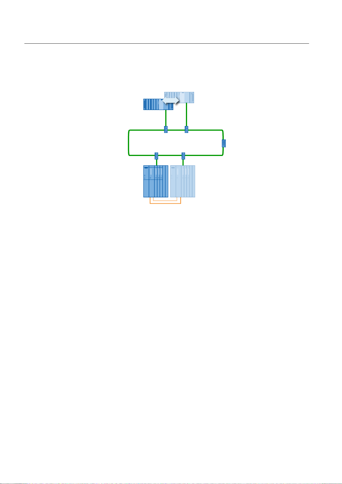
26VHUYHU
26VHUYHU
6ZLWFK0RGXOH
6&$/$1&(;
VSDWLDOO\VHSDUDWHG
PRGXOHUDFNVHDFKZLWK
WZR&3
6+
IDXOWWROHUDQW
DXWRPDWLRQV\VWHP
5HGXQGDQW26VHUYHUSDLU
)DXOWWROHUDQWSODQWEXV
6\QFKURQL]DWLRQOLQHV
6ZLWFKPRGXOHDV
UHGXQGDQF\PDQDJHU
,QGXVWULDO(WKHUQHW
Fault-tolerant Solutions in PCS 7
3.3 Solutions for communication
The following automation systems can be used:
● AS 41xH
Availability - ring structure
In this system, one CP 443-1 may fail in each subsystem of the AS without this affecting the
complete system.
The plant bus indicated by the asterisk ( * ) is set up with switches so that it is fault tolerant
and will tolerate a break on the bus cable at any point. One of the two switches to which the
OS servers are connected may fail without this affecting the complete system. If one switch
fails, the redundant OS partner server can continue to communicate using the operational
switch. The same scenario applies to the switches that each have a CP of a subsystem of the
H system connected.
To guard against the failure of all switches, however, the redundant double ring described in
the following section can be used.
58 Function Manual, 03/2012, A5E02779471-02
Fault-tolerant Process Control Systems (V8.0)
Page 59
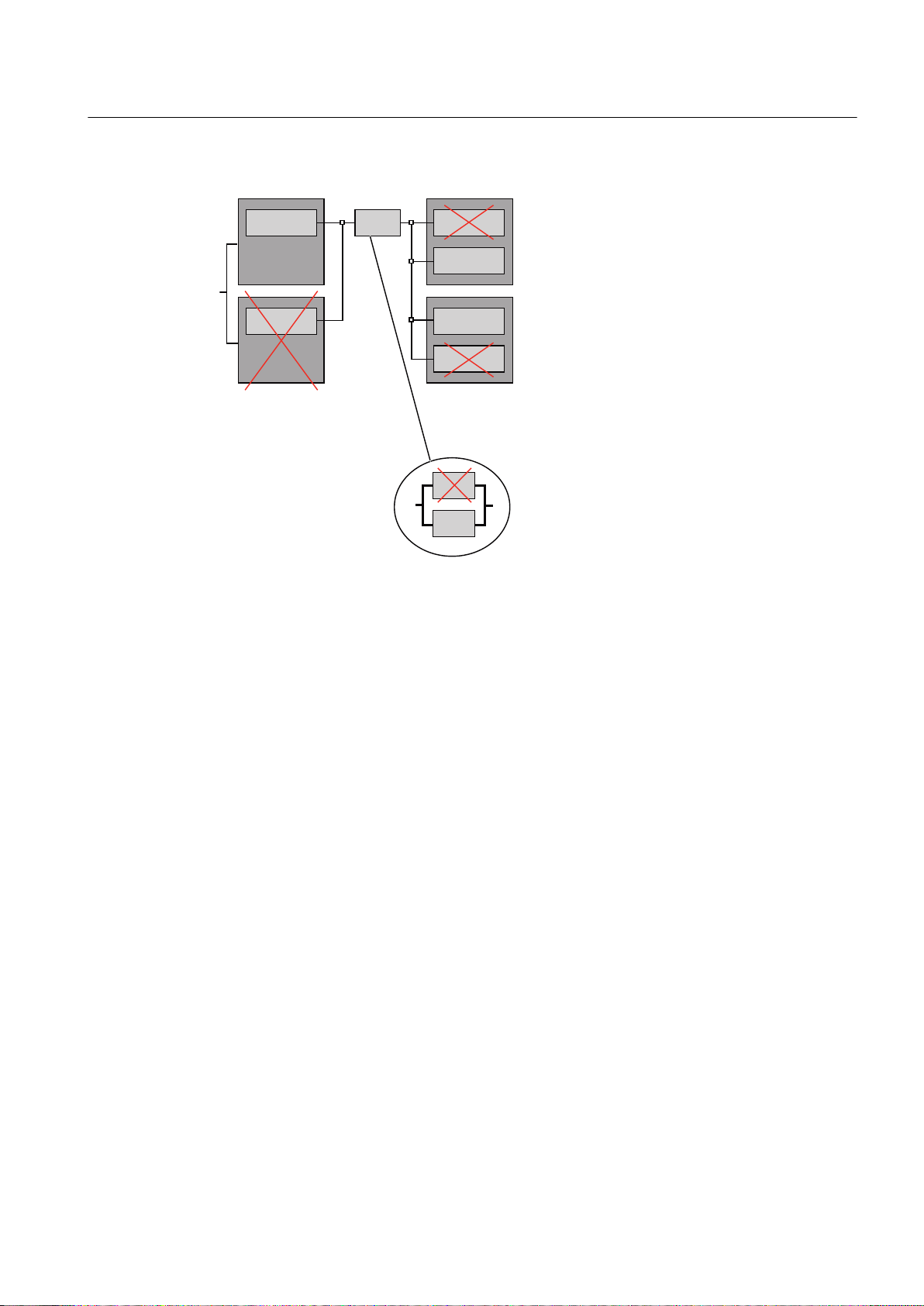
%XV
266HUYHU
%XV
%XV
+6\VWHPSDUW
+6\VWHPSDUW
26VHUYHU
&3
&3
&3
&3
&3
&3
Fault-tolerant Solutions in PCS 7
3.3 Solutions for communication
Additional information
● Section "How to configure a fault-tolerant plant bus (Page 100)"
● Manual
● Manual
● Manual
● Operating Instructions
SIMATIC Net Twisted Pair and Fiber-Optic Networks
SIMATIC NET Industrial Ethernet OSM/ESM Network Management
SIMATIC; Communication with SIMATIC
SIMATIC NET; Industrial Ethernet Switches SCALANCE X-400
3.3.4.3 Redundant, fault-tolerant plant bus
Functionality
The plant bus connects automation systems with servers (OS server, Route Control server).
The connection to a redundant, fault-tolerant plant bus is implemented with Ethernet
communications processors (CPs) that are installed in each subsystem of the automation
system and in the servers.
A redundant, fault-tolerant plant bus is set up using two identical, separate plant bus rings
(double ring). The network components ensure unrestricted operation of the plant bus. If a
plant bus fails, communication remains possible over the second plant bus.
Fault-tolerant Process Control Systems (V8.0)
Function Manual, 03/2012, A5E02779471-02 59
Page 60

6ZLWFK0RGXOH
ZLWKLQWHJUDWHG
UHGXQGDQF\FKDUDFWHULVWLFV
VSDWLDOO\VHSDUDWHG
PRGXOHUDFNVHDFKZLWK
WZR&3
26VHUYHU
26VHUYHU
6+
IDXOWWROHUDQW
DXWRPDWLRQV\VWHP
UHGXQGDQW26VHUYHUSDLUHDFK
ZLWKWZR&3
HJ&3
5HGXQGDQWIDXOWWROHUDQWSODQWEXV
6\QFKURQL]DWLRQOLQHV
%XV
%XV
,QGXVWULDO(WKHUQHW
Fault-tolerant Solutions in PCS 7
3.3 Solutions for communication
Redundant communication solutions
The following communication solutions are offered to prevent a possible failure:
● Redundant electrical or optical network with switches set up as Industrial Ethernet
● Combined redundant network with switches, FO cables and electrical connection
● Ring structures can be set up based on modular switches from the SCALANCE series.
(Can be implemented as optical, electrical and combined networks)
The following switches can be used:
● Switches of the SCALANCE series
Modules optical or electrical connection are used for the connection
● OSM (optical signal cables)
The connection to the OSMs is electrical or optical.
● ESM (electrical signal cables)
The connection to the ESM is electrical.
You can find additional information on the switches used with PCS 7 in the "Network
components (Page 41)" section.
Configuration - redundant, fault-tolerant plant bus
The figure below shows the basic structure of the redundant, fault-tolerant plant bus.
● Bus1 shows the functionally correct structure (shared switches for AS and OS).
● Bus2 shows the typical structure in PCS 7 plants (separate switches for AS and OS).
Note
Check the redundancy behavior of the individual components during commissioning.
Fault-tolerant Process Control Systems (V8.0)
60 Function Manual, 03/2012, A5E02779471-02
Page 61
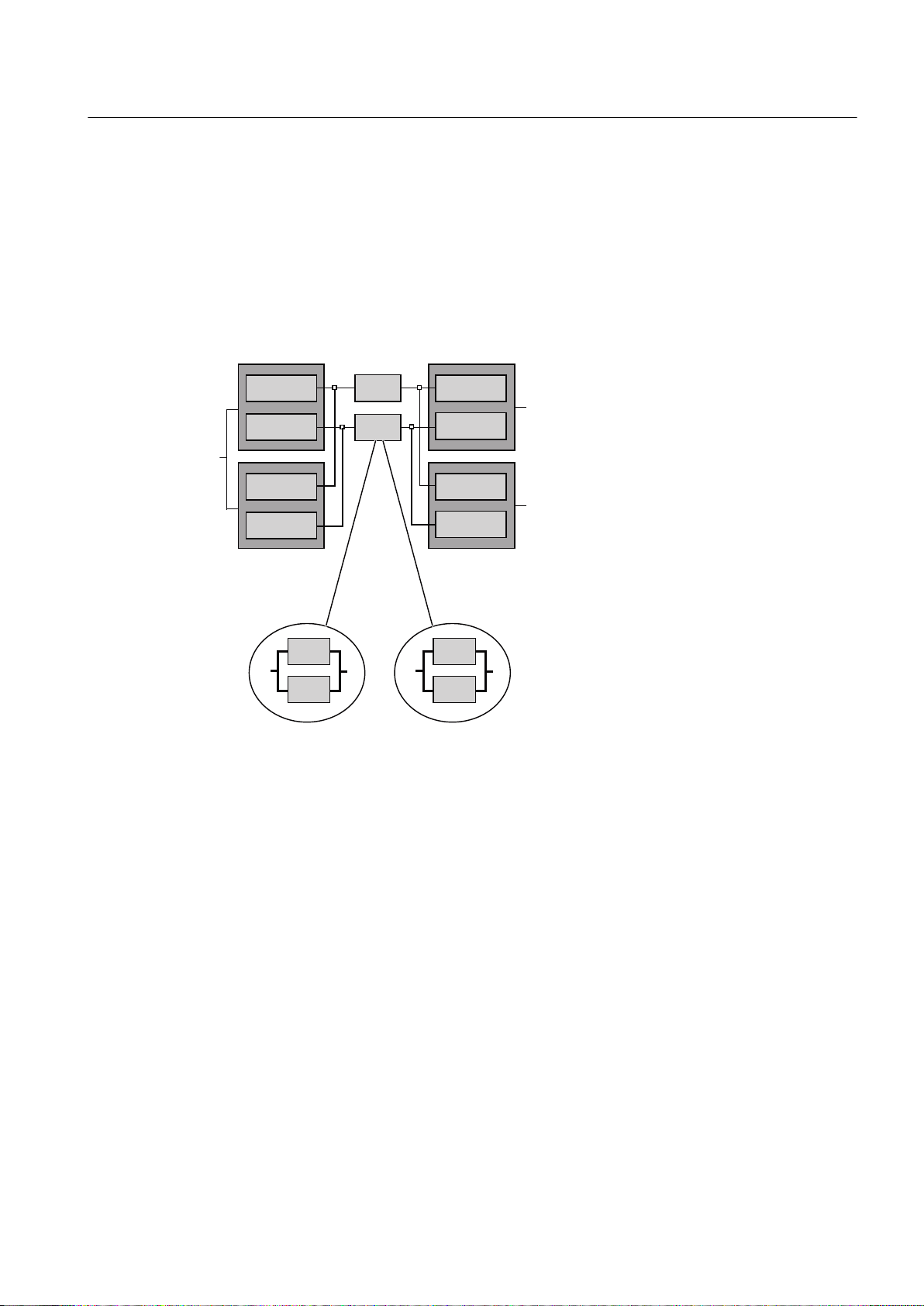
Availability - redundant, fault-tolerant plant bus
%XV
%XV
%XV
%XV
%XV
%XV
26VHUYHU
26VHUYHU
+6\VWHPSDUW
+6\VWHPSDUW
&3&3
&3
&3
&3
&3
&3
&3
The block diagram for a redundant, fault-tolerant plant bus with two CPs each in both OS
servers and additional switches appears as follows:
In this system, one CP 16x3 can fail in each OS server or one CP 443‑1 in each subsystem
of the AS without this affecting the complete system. There are two plant buses (busses), each
set up with redundant switches. This guards against the failure of the bus and all components
involved (switches).
Fault-tolerant Solutions in PCS 7
3.3 Solutions for communication
Additional information
● Section "Connecting PC stations to the plant bus (Page 56)"
● Section "Media Redundancy Protocol (Page 45)"
● Section "How to configure a fault-tolerant plant bus (Page 100)"
● Documentation
● Manual
Fault-tolerant Process Control Systems (V8.0)
Function Manual, 03/2012, A5E02779471-02 61
● Operating Instructions
● Manual
● Manual
PCS 7 Released Modules
SIMATIC Net Twisted Pair and Fiber-Optic Networks
SIMATIC NET; Industrial Ethernet Switches SCALANCE X-400
SIMATIC NET Industrial Ethernet OSM/ESM Network Management
SIMATIC Communication with SIMATIC
Page 62

Fault-tolerant Solutions in PCS 7
3.3 Solutions for communication
3.3.5 Solutions for the fieldbus
3.3.5.1 Redundant PROFIBUS DP
Functionality
The field bus is used for data exchange between the automation system (AS) and the
distributed I/O. PROFIBUS DP (distributed peripheral)-- the field bus standard for
manufacturing and process automation--is used. PROFIBUS DP includes the specifications
for the following elements:
● Physical bus characteristics
● Access method
● User protocol
● User interface
PROFIBUS DP is suitable for fast, cyclic data exchange with field devices. It is used to connect
distributed I/O, for example, ET 200M, with very fast response times.
It is often advantageous to connect several DP master systems to an automation system in
order to increase the number of I/O components that can be connected. This also enables
segments to be formed, allowing individual production areas to operate independent of one
another.
Fault-tolerant communication solutions
The following fault-tolerant communication solutions are offered for PROFIBUS DP:
● Redundant PROFIBUS DP as an electrical network
● Redundant PROFIBUS DP with OLMs (optical network)
Configuration
The S7-400H fault-tolerant automation system features a DP master interface on each CPU
for connecting to PROFIBUS DP. The redundant PROFIBUS DP connects the redundant DP
master to the redundant interface modules of the distributed I/O.
The following figure shows an example for connecting redundant distributed I/O based on ET
200M to a redundant PROFIBUS DP.
Fault-tolerant Process Control Systems (V8.0)
62 Function Manual, 03/2012, A5E02779471-02
Page 63
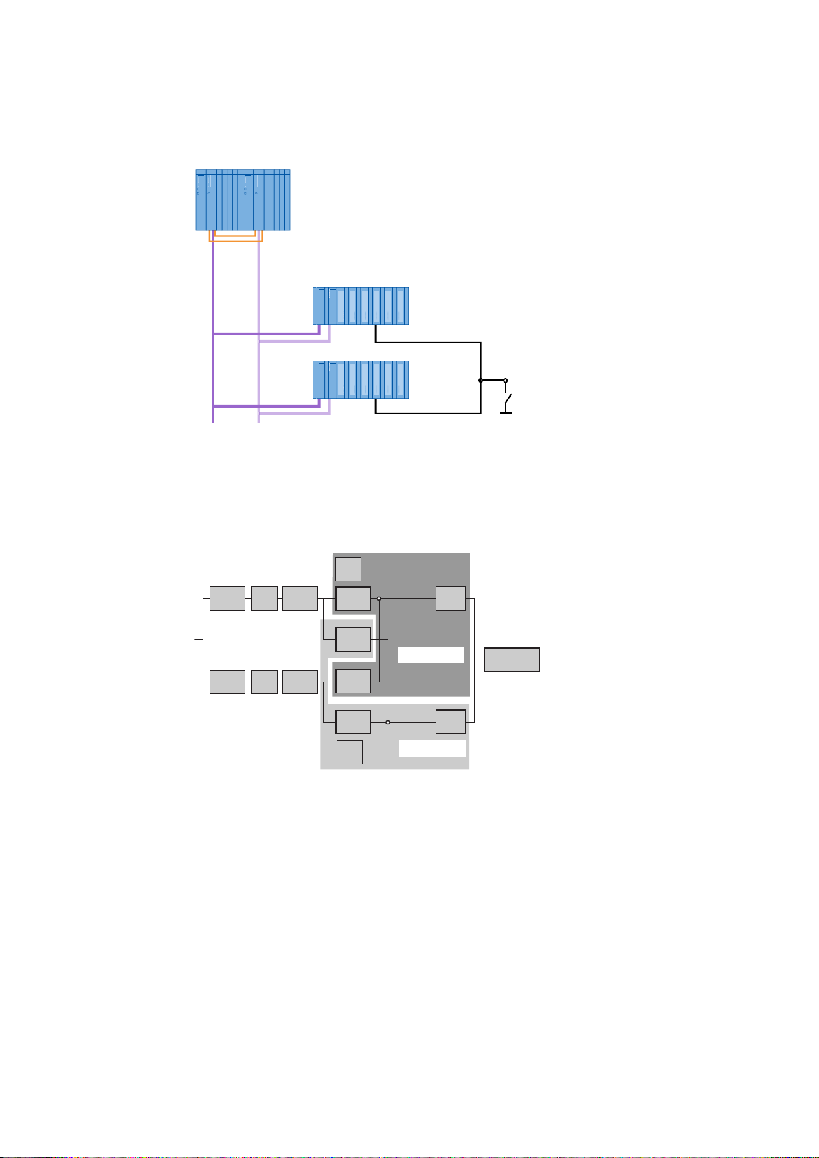
(70
[,0
(QFRGHU
5HGXQGDQWLQSXW
PRGXOH
6+
352),%86'3
Availability
6HQVRU
+6\VWHP
%XV
%XV
&38
&38&3&3
36
36
,0
,0
,0
,0
60
60
(70
,,
(70
,
Fault-tolerant Solutions in PCS 7
3.3 Solutions for communication
If the active PROFIBUS DP fails, sensors and H system can communicate with each other
over the redundant bus connection. The configuration shown in the following figure provides
increased availability due to the redundant interfacing of the distributed I/O.
Additional information
● Section "How to configure redundant PROFIBUS DP (Page 102)"
● Manual
● Manual
SIMATIC Net PROFIBUS Networks
SIMATIC; Communication with SIMATIC
Fault-tolerant Process Control Systems (V8.0)
Function Manual, 03/2012, A5E02779471-02 63
Page 64
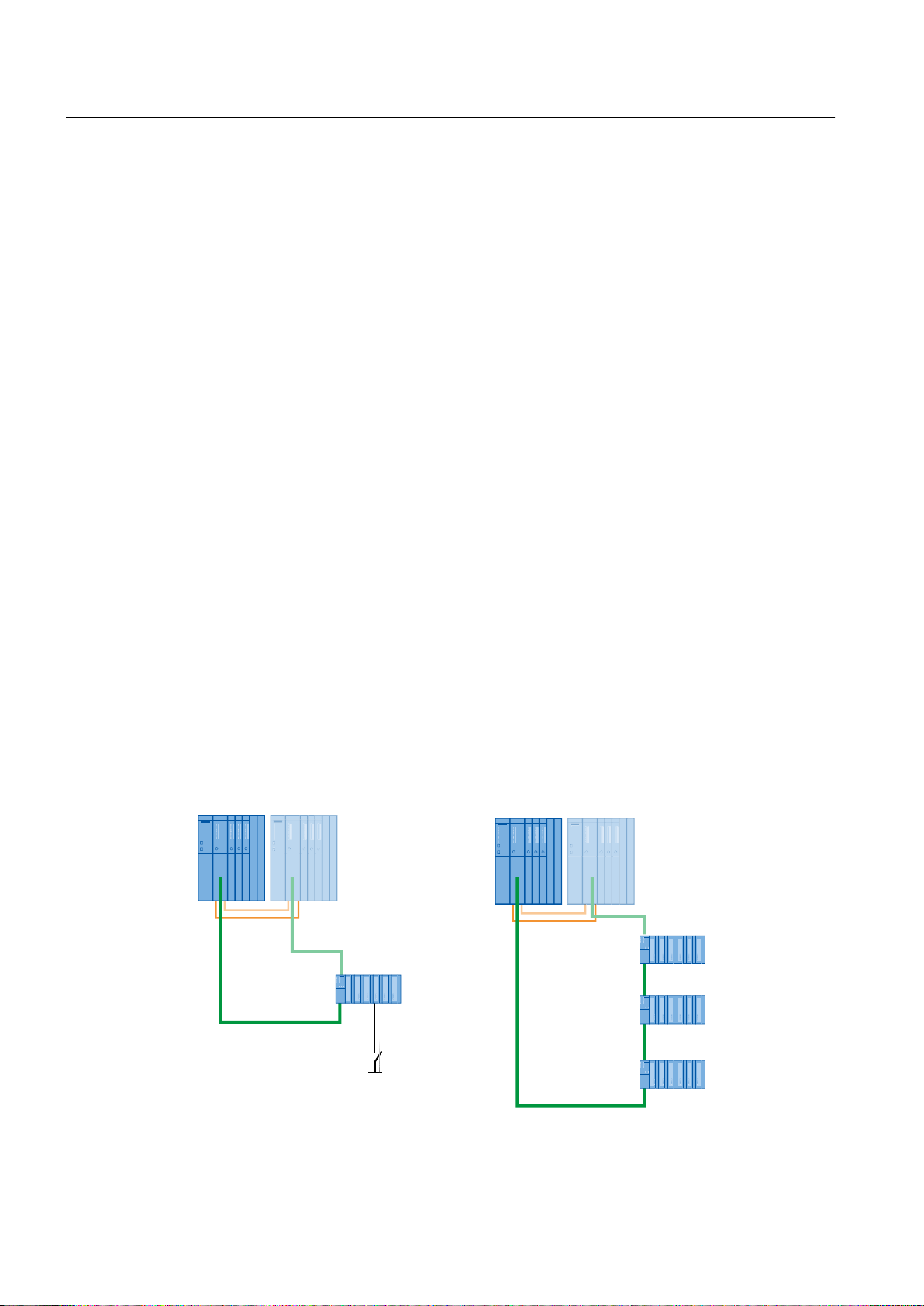
(QFRGHU
5LQJUHGXQGDQF\
,QSXWPRGXOH
352),1(7
352),1(7
352),1(7
352),1(7
(70
,031
(70
,031
6+31'36+31'3
Fault-tolerant Solutions in PCS 7
3.3 Solutions for communication
3.3.5.2 Fault-tolerant fieldbus based on PROFINET
Functionality
The fieldbus is used for data communication between the automation system (AS) and the
distributed I/O. PROFINET is a standard for manufacturing and process automation. The
PROFINET-based fieldbus comprises the specifications for the following elements:
● Physical bus characteristics
● Access method
● User protocol
● User interface
PROFINET is suitable for fast, cyclic data communication with field devices. It is used to
connect distributed I/O with very fast response times.
Fault-tolerant communication solutions
The following fault-tolerant communication solutions are offered for the PROFINET-based
fieldbus:
● Electrically designed network
● Optically designed network
Configurations
The S7-400H fault-tolerant automation system features a PROFINET interface on each CPU
4xx--5H PN/DP for connecting to PROFINET. The fault-tolerant PROFINET connects the CPU
with the distributed I/O.
The following figure shows the connection of I/O based on PROFINET.
Fault-tolerant Process Control Systems (V8.0)
64 Function Manual, 03/2012, A5E02779471-02
Page 65

*HEHU
+V\VWHP
%XV
%XV
&38
&38
36
,0
,0
60
(70
,
31'3
31'3
,0
Availability
Fault-tolerant Solutions in PCS 7
3.3 Solutions for communication
Note
Fault-tolerant PROFINET
It is absolutely necessary to operate the fieldbus ring with MRP (media redundancy protocol)
when using rings with PROFINET.
If the communication connection via a CPU fails, the stations of the distributed I/O can
communicate with the H system over the fault-tolerant bus line. The configuration shown in
the following figure provides increased availability due to the interfacing of the distributed I/O.
NOTICE
Changes to PROFINET modules only take effect when you load your hardware configuration
with the updated STEP 7 version to the CPU, which is in "STOP" mode.
Additional information
● Section "How to configure a fault-tolerant fieldbus on the basis of PROFINET (Page 105)"
● Manual
● Manual
● Manual
SIMATIC NET; PROFINET Networks
SIMATIC; Communication with SIMATIC
SIMATIC STEP 7; Modifying the System during Operation via CiR
3.3.5.3 Gateway between redundant and non-redundant PROFIBUS DP
Y Link
The Y Link consists of two IM 153-2 interface modules and a Y coupler that are interconnected
through the corresponding bus modules (BM IM/IM and BM Y coupler).
Fault-tolerant Process Control Systems (V8.0)
Function Manual, 03/2012, A5E02779471-02 65
Page 66

352),%86'3352),%86'3
UHGXQGDQW'3PDVWHUV\VWHP
QRQUHGXQGDQW'3PDVWHUV\VWHP
<FRXSOHU
)'&
&RQQHFWLRQRI
GLVWULEXWHG,2
GHYLFHVHJ
[,0
6+
(76
Fault-tolerant Solutions in PCS 7
3.3 Solutions for communication
Configuration
Functionality
The Y Link creates a gateway from the redundant DP master system of an S7-400H to a nonredundant DP master system. This enables devices with only one PROFIBUS DP interface to
be connected to a redundant DP master system as switched I/O.
The new generation of the Y Link no longer requires a repeater and is capable of forwarding
diagnostics requests from the corresponding function modules or I/O modules to the CPU.
DPV1 slaves can be connected downstream from the Y Link in addition to the standard
PROFIBUS DP slaves.
Additional information
● Section "How to configure the Y Link (Page 119)"
● Manual
DP/ PA Link and Y Link Bus Couplings
3.3.5.4 Connection of PROFIBUS PA to PROFIBUS DP
DP/PA Link
The DP/PA Link allows a connection between PROFIBUS DP and PROFIBUS PA. DP/PA link
includes the following modules, which are interconnected via the backplane bus:
66 Function Manual, 03/2012, A5E02779471-02
● Interface module IM 153-2
● one or more FDC 157 DP/PA couplers
Fault-tolerant Process Control Systems (V8.0)
Page 67

Configuration
'33$/LQN
[,0[)'&
352),%863$
352),%86'3352),%86'3
6+
Functionality
Fault-tolerant Solutions in PCS 7
3.3 Solutions for communication
The DP/PA Coupler is a transceiver that interconnects PROFIBUS DP and PROFIBUS PA
and decouples the various transmission rates. It is a slave on the PROFIBUS DP and a master
on the PROFIBUS PA. Seen from the automation system, the DP/PA Link is a modular slave.
The individual modules of this slave are the field devices that are connected to the lower-level
PROFIBUS PA lines.
Versions
The PA devices connected to the PROFIBUS PA are assembled at a PROFIBUS address by
DP/PA Link.
The DP/PA link can be connected directly to the PROFIBUS DP interface of programmable
controllers (S7 400) for the coupling between PROFIBUS DP and PROFIBUS PA.
You can connect a PROFIBUS PA to the PROFIBUS DP. The following variants can be
realized:
● Connection to a singular PROFIBUS DP
– Connection via DP/PA Link (1 x interface module, 1 x DP/PA coupler)
– Connection via DP/PA coupler (45.45 Kbps on PROFIBUS DP)
– Connecting a redundant PROFIBUS PA:
You can find additional information on this in the section "Fault-tolerant PROFIBUS PA
(Page 68)".
● Connection to a redundant PROFIBUS DP
– Connection of a singular PROFIBUS PA via DP/PA Link with redundant interconnection
(2 x interface module and 1 x DP/PA coupler)
– Connecting a redundant PROFIBUS PA:
You can find additional information on this in the section "Fault-tolerant PROFIBUS PA
(Page 68)".
Fault-tolerant Process Control Systems (V8.0)
Function Manual, 03/2012, A5E02779471-02 67
Page 68

Fault-tolerant Solutions in PCS 7
3.3 Solutions for communication
Physical bus characteristics
● The application protocols for PROFIBUS DP and PROFIBUS PA are defined according to
IEC 61158-2 and are identical for these two fieldbus variants.
– You can set the transmission speed on the PROFIBUS DP. The maximum transmission
speed with the Y-link is 12 Mbps.
– The transmission speed on the PROFIBUS PA is 31.25 Kbps.
● If the DP/PA coupler is connected directly on PROFIBUS DP, the transfer rate is set to
45.45 Kbps. The DP/PA coupler can be operated with SIMATIC S7 automation systems
and all DP masters that support the transmission rate of 45.45 Kbps.
● Depending on the power consumption of the PA devices, up to 31 PA devices can be
connected to the PROFIBUS PA.
Use in hazardous areas
● The intrinsically safe PROFIBUS DP is specified for the type of protection EEx(ib).
● The following components can be used in operating environments of the Ex zone:
– DP/PA link in Ex version, up to Ex Zone 2
– DP/PA link or FDC 157-0 DP/PA coupler in a housing that meets at least degree of
protection IP54; up to Ex Zone 2
– DP/PA coupler Ex [i] cannot be used for redundant configuration (coupler redundancy,
ring); up to Ex Zone 1
● If you use a SIMATIC AFDiS as a field barrier between the DP/PA link or DP/PA coupler
and the field devices, you can connect the field devices in hazardous areas of Zone 0 or
Zone 1. The outputs of the SIMATIC AFDiS fulfill the requirements for types of protection
EEx(ia) and EEx(ib).
● The number of devices is limited by the current.
Additional information
● Section "Configuring DP/PA Link (Page 122)"
● Section "Fault-tolerant PROFIBUS PA (Page 68)"
● Section "How to configure the redundant PROFIBUS PA (Page 107)"
● Manual
DP/ PA Link and Y Link Bus Couplings
3.3.5.5 Fault-tolerant PROFIBUS PA
Functionality
PROFIBUS PA allows the connection of PA devices. A redundant PROFIBUS PA is connected
to FDC 157-0 redundant DP/PA couplers. If the communication path of the PROFIBUS PA
fails, the communication path is preserved as far as the spur line to the field devices.
Fault-tolerant Process Control Systems (V8.0)
68 Function Manual, 03/2012, A5E02779471-02
Page 69

Fault-tolerant communication solutions
The following communication solutions are offered to prevent a possible failure:
● Ring redundancy with the AFD (Active Field Distributor)
● Coupler redundancy with the AFS (Active Field Splitter)
Fault-tolerant Solutions in PCS 7
3.3 Solutions for communication
The DP/PA coupler can be used stand-alone or in the DP/PA-Link .
Note
Mixed configurations
You can connect only one redundant DP/PA coupler pair per DP/PA-Link . In mixed
configurations, you can operate up to 3 additional non-redundant DP/PA couplers. The
coupler pair (FDC 157-0 DP/PA coupler) should be installed for redundant operation in the
last two slots of the ET 200 station.
Connecting the fault-tolerant PROFIBUS PA to PROFIBUS DP
You can connect a fault-tolerant PROFIBUS PA to the PROFIBUS DP. The following variants
can be realized:
● Connection to a redundant PROFIBUS DP
– Connection of a fault-tolerant PROFIBUS PA via redundant DP/PA-Link
(2 x interface module and 2 x DP/PA coupler)
● Connection to a singular PROFIBUS DP
– Connection of a fault-tolerant PROFIBUS PA via DP/PA-Link with redundant coupler
pair (1 x interface module and 2 x DP/PA coupler)
– Connection of a fault-tolerant PROFIBUS PA with redundant FDC 157 coupler pair
(2 x DP/PA coupler directly on the PROFIBUS DP)
We recommend the following configuration limits in PCS 7 when connecting PA devices using
AFD or AFS :
● For the purpose of increasing availability when using ring redundancy (fault-tolerant
connection), connect a maximum of 4 field devices (one field device per spur line) to an
active field distributor AFD (maximum of 8 AFD to a redundant DP/PA coupler). You can
connect a total of 31 field devices.
● Connect an active field splitter (AFS) to a redundant coupler in the case of coupler
redundancy. Connect the field devices via AFD (max. 8 AFD). For the purpose of increasing
availability, connect a maximum of 4 field devices per AFD.
● You can connect a maximum of 31 field devices per PROFIBUS PA.
● The maximum power consumption of 1 A must not be exceeded. This figure includes all
components connected to the PROFIBUS PA.
Fault-tolerant Process Control Systems (V8.0)
Function Manual, 03/2012, A5E02779471-02 69
Page 70

$)6
$)'$)'L6
$)'$)'L6
'33$OLQNZLWKUHGXQGDQW,0
DQGUHGXQGDQW'33$
FRXSOHU)'&
'33$OLQNZLWKUHGXQGDQW,0
DQGUHGXQGDQW'33$
FRXSOHU)'&
PD[
PD[$)'
PD[
352),%86'3352),%86'3
6+
352),%863$
352),%863$
Fault-tolerant Solutions in PCS 7
3.3 Solutions for communication
Configuration
Examples for connections of field devices via AFD and AFS are shown in the following figures.
Figure 3-1 Connection to a redundant PROFIBUS DP
70 Function Manual, 03/2012, A5E02779471-02
Fault-tolerant Process Control Systems (V8.0)
Page 71

GLUHFWFRQQHFWLRQWR
352),%86'3UHGXQGDQW
'33$FRXSOHU)'&
'33$OLQNZLWKVLQJXODU,0
DQGUHGXQGDQW
'33$FRXSOHU)'&
PD[
PD[$)'
PD[
$)6
$)'$)'L6
$)'$)'L6
352),%86'3352),%86'3
352),%863$
352),%863$
$)'
Fault-tolerant Solutions in PCS 7
3.3 Solutions for communication
Transmission rate
Availability - redundant interfacing
Figure 3-2 Connection to a singular PROFIBUS DP
You have two interfacing options for the gateway between PROFIBUS DP and PROFIBUS
PA. These result in different transmission rates on PROFIBUS DP.
● If you connect the DP/PA couplers via a DP/PA-Link , a transmission rate of up to 12 Mbps
is possible on the PROFIBUS DP.
● If you connect the DP/PA couplers directly, the transmission rate on PROFIBUS DP is 45.45
Kbps.
● The transmission speed on the PROFIBUS PA is 31.25 Kbps.
In a redundant system, we recommend that you implement the connection to the PROFIBUS
DP redundantly (redundant IM 153-2).
If a PA bus cable, an IM 153-2 or a DP/PA coupler fails, the communication connection to the
field devices is retained. The AFD or AFS automatically switches the connection to the
available signal path.
Fault-tolerant Process Control Systems (V8.0)
Function Manual, 03/2012, A5E02779471-02 71
Page 72

3$GHYLFH
3$GHYLFH
3$GHYLFH
,0
,0
'33$&RXSOHU
'33$&RXSOHU
%XV
%XV
352),%863$
.ESV
352),%86'3
PD[0ESV
&38
&3
&38
&3
$)'$)'$)'
[,0))
352),%86'3352),%86'3
6+
)281'$7,21)LHOGEXV
<.RSSOHU
)'&
Fault-tolerant Solutions in PCS 7
3.3 Solutions for communication
Additional information
● Section " Connection of PROFIBUS PA to PROFIBUS DP (Page 66)"
● Section "How to configure redundant PROFIBUS PA (Page 107)"
● Operating Instructions
SIMATIC; DP/PA Coupler, DP/PA Link and Y Link Bus Couplers
3.3.5.6 Connecting the FOUNDATION Fieldbus to PROFIBUS DP
FF Link
FF Link enables connection between PROFIBUS DP and FOUNDATION Fieldbus. FF Link
includes the following modules, which are interconnected via the backplane bus:
● Interface module IM 153-2 FF
● Coupler module FDC 157
Configuration
72 Function Manual, 03/2012, A5E02779471-02
Fault-tolerant Process Control Systems (V8.0)
Page 73

Functionality
Versions
Fault-tolerant Solutions in PCS 7
3.3 Solutions for communication
FF Link connects PROFIBUS DP and FOUNDATION Fieldbus with one another and decouples
various transmission rates. It is a slave on the PROFIBUS DP and master on the
FOUNDATION Fieldbus. From the point of view of the automation system, the FF Link is a
modular slave. The individual modules of this slave are the field devices that are connected
to the lower-level FF segment.
The FF devices connected to the FF segment are assembled at one PROFIBUS address by
the FF Link .
The FF Link can be connected directly to the PROFIBUS DP interface of data record gateway
capable PLCs for the coupling between PROFIBUS DP and FOUNDATION Fieldbus .
You can connect one FF segment to the PROFIBUS DP for each FF Link . The following
variants can be realized:
● Connection to a singular PROFIBUS DP
– Connection via FF Link (1 x IM 153-2 FF, 1 x FDC 157)
– Connection of a redundant FF segment:
Additional information on this topic can be found in the "Configuring FF Link (Page 124)"
section.
● Connection to a redundant PROFIBUS DP
– Connection of a singular FOUNDATION Fieldbus via FF Link to a redundant interface
(2 x IM 153-2 FF und 1 x FDC 157)
– Connection of a redundant FF segment:
For additional information, refer to the section titled "Fault-tolerant FOUNDATION
Fieldbus (Page 74)".
Physical bus characteristics
● The application protocols for PROFIBUS DP and FOUNDATION Fieldbus are determined
according to IEC 61158-2.
– You can set the transmission speed on the PROFIBUS DP . The maximum transmission
rate is 12 Mbps.
– The transmission speed on the FOUNDATION Fieldbus is 31.25 Kbps. The transmission
method is determined by IEC 61158-2 .
● Depending on the power consumption of the FF devices, up to 31 FF devices can be
connected to the FOUNDATION Fieldbus .
Use in hazardous areas
● The intrinsically safe PROFIBUS DP is specified for the type of protection EEx(ib) .
● When the FF Link is built into an enclosure conforming to at least an IP 54 degree of
protection, the FF Link can be installed in operating environments up to Ex Zone 2.
Fault-tolerant Process Control Systems (V8.0)
Function Manual, 03/2012, A5E02779471-02 73
Page 74

Fault-tolerant Solutions in PCS 7
3.3 Solutions for communication
● If you use a SIMATIC AFDiS as a field barrier between the FF Link and the field devices,
you can connect the field devices in hazardous areas of zones 0 or 1. The outputs of the
SIMATIC AFDiS fulfill the requirements for types of protection EEx(ia) and EEx(ib).
● The number of devices is limited by the current.
Additional information
● Documentation
● Documentation
SIMATIC; Process Control System PCS 7; PCS 7 Readme
SIMATIC; PCS 7 process control system; PCS 7 in-Practice;
FOUNDATION Fieldbus
● Operating instructions
SIMATIC; Bus links; FF Link bus link
3.3.5.7 Fault-tolerant FOUNDATION Fieldbus
Functionality
PCS 7 enables the connection of field devices to the FOUNDATION Fieldbus H1 (referred to
only as FOUNDATION Fieldbus or FF from this point). A fault-tolerant FOUNDATION Fieldbus
is connected to the redundantly configured FF Link . If the transmission path fails, the
communication path of the FOUNDATION Fieldbus is preserved as far as the spur line to the
field devices.
Fault-tolerant communication solutions
The following communication solutions are offered to prevent a possible failure:
● Ring redundancy with the AFD (Active Field Distributor)
● Coupler redundancy with the AFS (Active Field Splitter)
Connection of the fault-tolerant FOUNDATION Fieldbus to PROFIBUS DP
You can connect a fault-tolerant FOUNDATION Fieldbus to the PROFIBUS DP . The following
variants can be realized:
● Connection to a redundant PROFIBUS DP
– Connecting a fault-tolerant FOUNDATION Fieldbus via redundant FF Link
(2x IM 153-2 FF, 2 x FDC 157)
● Connection to a singular PROFIBUS DP
– Connecting a fault-tolerant FOUNDATION Fieldbus via FF Link with redundant coupler
pair (1x IM 153-2 FF, 2 x FDC 157)
– Connecting a fault-tolerant FOUNDATION Fieldbus with redundant FDC 157 coupler
pair (2 x FDC 157 directly on the PROFIBUS DP)
We recommend the following configuration limits in PCS 7 when connecting FF devices using
AFD or AFS :
Fault-tolerant Process Control Systems (V8.0)
74 Function Manual, 03/2012, A5E02779471-02
Page 75
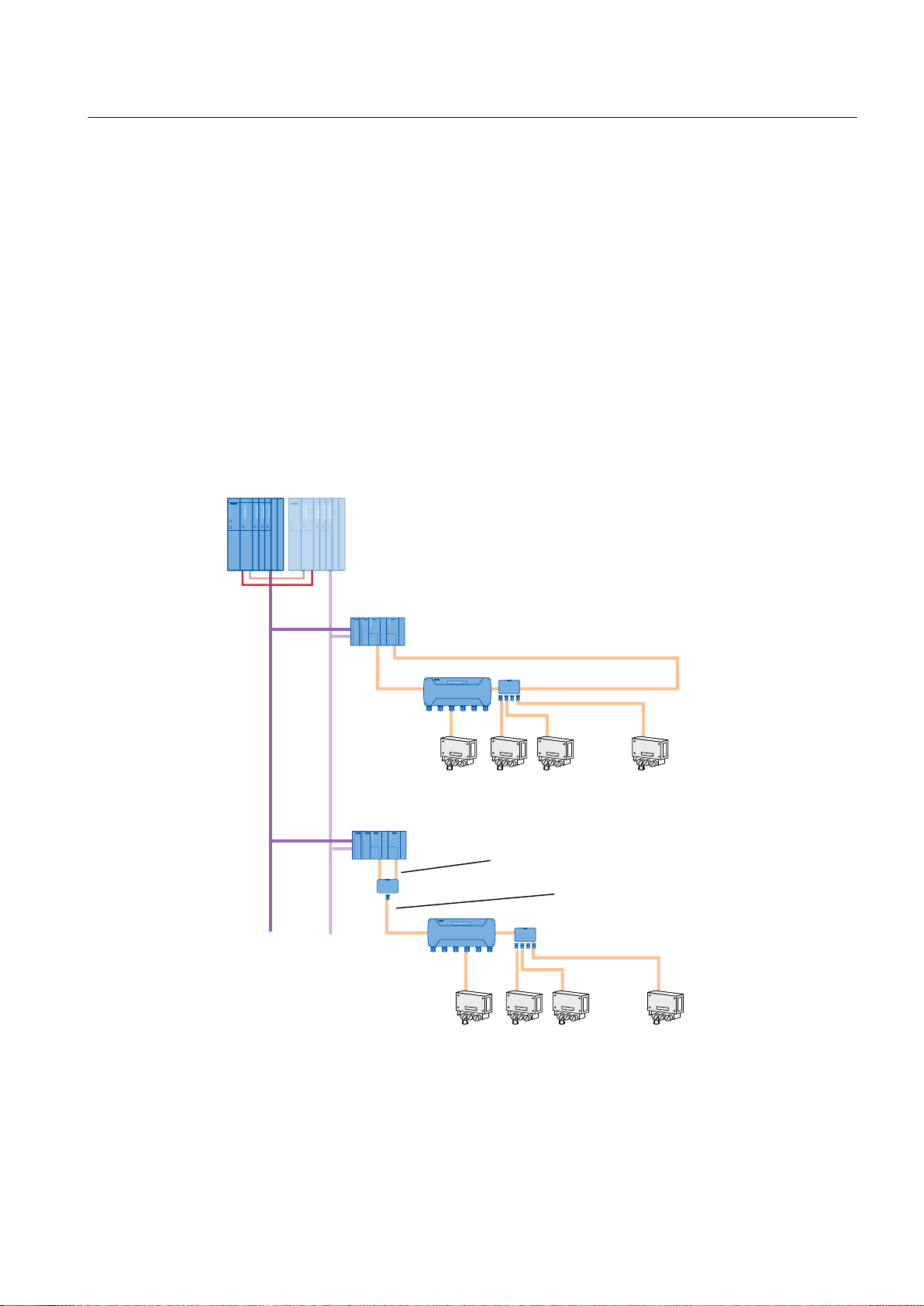
Configuration
))OLQNZLWKUHGXQGDQW,0
))DQGUHGXQGDQW
FRXSOHU)'&
))OLQNZLWKUHGXQGDQW,0
))DQGUHGXQGDQW
FRXSOHU)'&
PD[
PD[$)'
)281'$7,21
)LHOGEXV
)DXOWWROHUDQW
)281'$7,21
)LHOGEXV
PD[
PD[$)'
$)'L6$)'
PD[
UHGXQGDQW'3
PDVWHUV\VWHP
UHGXQGDQW'3
PDVWHUV\VWHP
)281'$7,21
)LHOGEXV
)DXOWWROHUDQW
PD[
352),%86'3352),%86'3
6+
$)'L6
$)'
$)6
Fault-tolerant Solutions in PCS 7
3.3 Solutions for communication
● You can connect one FF segment to the FF Link .
● For the purpose of increasing availability when using ring redundancy (fault-tolerant
connection), connect a maximum of 4 field devices (one field device per spur line) to an
active field distributor AFD(maximum of FDC 157 8 AFD to a redundant coupler).
● Connect an active field splitter (AFS) to a redundant coupler in the case of coupler
redundancy. Connect the field devices via AFD (max. 8 AFD). For the purpose of increasing
availability, connect a maximum of 4 field devices per AFD.
● You can connect a maximum of 31 field devices per FF segment.
● The maximum power consumption of 1 A must not be exceeded. This figure includes all
components connected to the FF segment.
Examples for connections of field devices via AFD and AFS are shown in the following figures.
Fault-tolerant Process Control Systems (V8.0)
Function Manual, 03/2012, A5E02779471-02 75
Figure 3-3 Connection to a redundant PROFIBUS DP
Page 76

PD[
PD[$)'
)281'$7,21
)LHOGEXV
)DXOWWROHUDQW
)281'$7,21
)LHOGEXV
PD[
PD[$)'
PD[
)281'$7,21
)LHOGEXV
)DXOWWROHUDQW
PD[
GLUHFWFRQQHFWLRQWR
352),%86'3
UHGXQGDQWFRXSOHU)'&
))OLQNZLWKVLQJXODU,0
))DQGUHGXQGDQW
FRXSOHU)'&
$)'L6$)'
352),%86'3352),%86'3
$)'L6$)'
$)6
Fault-tolerant Solutions in PCS 7
3.3 Solutions for communication
Transmission rate
Availability - fault-tolerant interfacing
Figure 3-4 Connection to a singular PROFIBUS DP
You have two interconnection options for the gateway between PROFIBUS DP and
FOUNDATION Fieldbus . These result in different transmission rates on PROFIBUS DP.
● If you connect via an FF Link , a transmission rate of up to 12 Mbps is possible on
PROFIBUS DP.
● If you connect the FDC 157 coupler directly, the transmission rate on PROFIBUS DP is
45.45 Kbps.
● The transmission speed on the FOUNDATION Fieldbus is 31.25 Kbps.
In a redundant system, we recommend that you implement the interface to PROFIBUS DP
redundantly (redundant IM 153-2 FF).
If an FF line, (IM 153-2 FF) interface module or (FDC 157) coupler fails, the communication
connection to the field devices is maintained. The AFD or AFS automatically switches the
connection to the available signal path.
76 Function Manual, 03/2012, A5E02779471-02
Fault-tolerant Process Control Systems (V8.0)
Page 77

))GHYLFH
))GHYLFH
))GHYLFH
,0))
,0))
)'&
)'&
%XV
%XV
)281'$7,21)LHOGEXV
.ESV
352),%86'3
PD[0ESV
&38
&3
&38
&3
$)'$)'$)'
Additional information
● Section "Connecting the FOUNDATION Fieldbus to PROFIBUS DP (Page 72)"
● Section "Configuring FF Link (Page 124)"
Fault-tolerant Solutions in PCS 7
3.5 Solutions for OS servers
● Documentation
● Documentation
SIMATIC; Process Control System PCS 7; PCS 7 Readme
SIMATIC; PCS 7 process control system; PCS 7 in-Practice;
FOUNDATION Fieldbus
● Operating instructions
SIMATIC; Bus links; FF Link bus link
3.4 Solutions for integrating a PCS 7 plant in a domain
For additional information, please refer to the following documents:
● Function manual
Process Control System PCS 7; Time Synchronization
● On the Internet pages of Customer Support in Whitepaper SIMATIC; Safety Concept PCS
7 and WinCC; Basic document (http://support.automation.siemens.com/WW/view/en/
26462131)
3.5 Solutions for OS servers
Redundant OS servers
PCS 7 enables you to configure two OS servers redundantly for fault-tolerant operation. This
ensures that you can monitor and control your process at all times. The solution represents
the entry level into fault-tolerant process control systems.
Fault-tolerant Process Control Systems (V8.0)
Function Manual, 03/2012, A5E02779471-02 77
Page 78
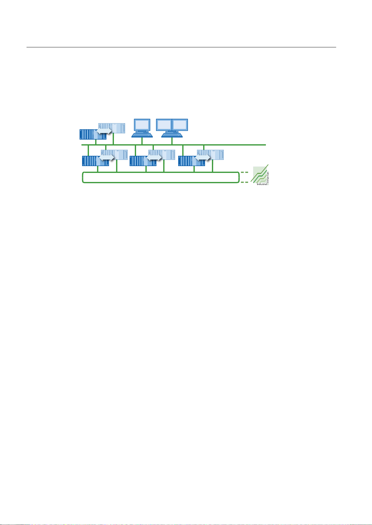
,QGXVWULDO(WKHUQHWWHUPLQDOEXV
,QGXVWULDO(WKHUQHWSODQWEXV
$UFKLYHVHUYHU
26FOLHQWV
PD[LQPXOWLFOLHQWRSHUDWLRQ
26VHUYHU
PD[UHGXQGDQW
Fault-tolerant Solutions in PCS 7
3.5 Solutions for OS servers
Configuration
The figure below shows an example of a configuration with redundant OS server and redundant
central archive server.
Functionality
Redundant OS servers monitor each other in runtime. If one OS partner server fails, the event
is detected in time.
If one of the two OS server fails, the OS partner server takes over the process. The interface
between OS clients and the automation system remains available.
The OS clients are automatically switched to the redundant OS partner server. This means
that the OS clients always remain available for the control and monitoring of the process. During
the failure period, the redundant OS partner server continues to archive all messages and
process data in the WinCC project. Once the failed OS server comes back online, the contents
of all the message, process value and user archives are automatically copied to the returning
OS server. This copy process is referred to as redundancy synchronization. Redundancy
synchronization fills the gaps in the various archives that result from failures.
During the failure period, the internal master/standby identification changes from the failed OS
server to its OS partner server. The master identification remains with the OS partner server
even when the failed OS server comes back online.
Configuring the archives
Tag logging and alarm logging have to be configured functionally identical for redundant OS
servers. Functionally identical configuration means the same archives, whereby extensions in
the form of additional measuring points and archives are permitted.
OS partner servers (OS_Stby) are configured in the SIMATIC Manager. Using the menu
command PLC > Download synchronizes the functionality.
Redundant external archive server
78 Function Manual, 03/2012, A5E02779471-02
If an external archive server of a server pair fails, the data is automatically synchronized on
the return of the failed external archive server.
PCS 7 provides the following options for centralized collection of archive information for the
process control system:
Fault-tolerant Process Control Systems (V8.0)
Page 79
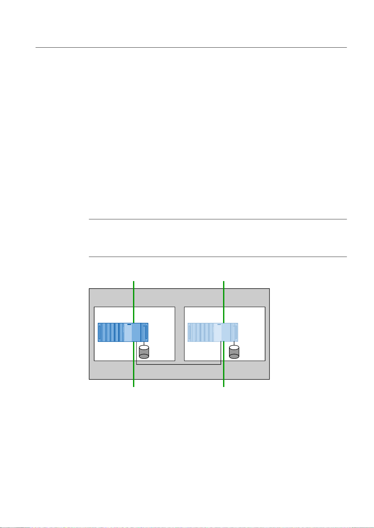
● Process Historian
26
VHUYHU
26
VHUYHU
$UFKLYH
:LQ&&
SURMHFW$
$UFKLYH
:LQ&&
SURMHFW$v
5HGXQGDQW26VHUYHUSDLU
&RQQHFWLQJWRWKHSODQWEXV
&RQQHFWLRQWRWKHWHUPLQDOEXV
5HGXQGDQF\FRQQHFWLRQ
You can set up two Process Historians with redundancy functionality for fault-tolerant
operation. The associated information server can be configured in such a way that it
connects to the active Process Historian to execute tasks.
● Central archive server
You can set up two central archive servers with redundancy functionality for fault-tolerant
operation.
This server does not require a connection to the plant bus.
Redundant maintenance station
PCS 7 allows you to configure two maintenance servers with redundancy functionality for faulttolerant operation.
Setting up a redundant OS server
Fault-tolerant Solutions in PCS 7
3.5 Solutions for OS servers
The following configuration shows the basic operating principle of redundant OS servers.
Note
You need to connect the redundant PC stations through a redundancy connection. This
connection offers security against problematic behavior during communication between the
OS servers.
Fault-tolerant Process Control Systems (V8.0)
Function Manual, 03/2012, A5E02779471-02 79
Page 80

%XV%XV
26VHUYHU
26VHUYHU
Fault-tolerant Solutions in PCS 7
3.5 Solutions for OS servers
Redundancy connection
You need the following components to make the redundancy connection, depending on the
distance to be bridged:
Maximum distance Required components Connection
10 m Null modem cable Serial connection
100 m ● Crossover network cable
1000 m Fiber-optic cable
Ethernet connection
● Per server: A free network connection (see
section "Network components (Page 41)")
Ethernet connection
Per server:
● A free network connection
(see section "Network components
(Page 41)")
● 1 Ethernet cable
● 1 media converter
(e.g., SCALANCE X101-1)
Availability
The availability of the complete system is ensured even if one of the two OS servers fails
because the two OS servers form an independent redundancy node.
Note
The buses marked with * (terminal bus and plant bus) can be configured redundantly with
optical or electronic switch modules.
Delaying the transfer of archives
If a redundant partner is not available or is deactivated, the transfer of the archives of the
redundant partner will be delayed. The transfer of archives is started or continued only when
the partner becomes available again and synchronization of the archives is completed.
Since the storage capacity of the ring buffer for Tag Logging and Alarm Logging is limited,
there is a risk of data loss if the redundant partner is out of action for a longer period of time.
Additional information
● Section "Network components (Page 41)"
● Section "How to configure an OS server and its redundant OS partner server (Page 127)"
80 Function Manual, 03/2012, A5E02779471-02
Fault-tolerant Process Control Systems (V8.0)
Page 81

Fault-tolerant Solutions in PCS 7
3.6 Solutions for OS clients
● Online help for
● Documentation on the Process Historian
● Section "How to configure a central archive server and its redundant archive partner
server (Page 130)"
WinCC; WinCC Redundancy
3.6 Solutions for OS clients
3.6.1 Additional OS clients
Additional OS clients
OS clients are PC stations that are used for control and monitoring of an automation process.
They are connected to the OS servers through the terminal bus. The OS servers form the
process connection to the automation system.
An OS client has its own WinCC project and visualizes the process data generated on an OS
server.
If an OS client fails, this does not disrupt the overall process because the automation program
in the CPU continues to control the process and the OS servers continue to process and archive
the process data. However, the visualization of the process is lost and you can only influence
the process through the OS servers. You should therefore protect against such failure by
integrating additional OS clients.
By specifying a preferred server, you can distribute multiple OS clients between the redundant
OS servers. The automation process can therefore be operated continuously, even during a
failover from the active OS to its OS partner server.
Additional information
● Section " How to configure an OS client (Page 144) "
● Online help for
3.6.2 Permanent operability
Permanent operability
"Permanent operability" in a redundant environment is the unrestricted ability to influence the
system at any time even when confronted with the failure of one of the redundant OS servers.
It is the most important safety characteristic for plants with critical operations.
This function is important in all systems in which the ability to handle failure of an OS server
in a redundant configuration is not enough and in which continuous control of a process must
be maintained. In the event of an OS server failure, all OS clients connected to the failed server
will temporarily lose their connection to the process while they switch over. In order to ensure
WinCC
Fault-tolerant Process Control Systems (V8.0)
Function Manual, 03/2012, A5E02779471-02 81
Page 82

Fault-tolerant Solutions in PCS 7
3.7 Solutions for SIMATIC BATCH
that the OS clients can control and monitor the automation process continuously, the OS clients
are distributed between the redundant OS servers with specification of a preferred OS server.
The failure of some OS clients can therefore be tolerated because the other clients remain
connected to the process.
Preferred server
A "preferred server" is an OS server in the redundant OS server pair that the OS client connects
to preferentially. A preferred server can be defined separately for each OS client in order to
ensure permanent operability. The distribution of the OS clients between the OS servers
distributes the loads and increases the performance of the system as a whole.
Operating principle
If the active OS server fails, the process values on all of the connected OS clients are no longer
updated and there is no operator control on these OS clients during the failover. Other OS
clients that are connected in parallel to the redundant OS partner server are not affected by
this. The plant operator can therefore change to these OS clients if needed.
Generally, the following applies: The OS clients always connect to the specified preferred
server if it is available. If it is not available, the OS clients automatically connect to its redundant
OS partner server. If you do not specify a preferred server for an OS client, it will connect to
the OS server that has the master identification.
When the failed OS server comes online again, the OS client automatically reconnects to its
preferred server. The master identification of the OS server does not change even when the
failed OS server comes back online.
Additional information
● Section "How to configure an OS client for permanent operability (Page 145)"
● Online help for
WinCC
3.7 Solutions for SIMATIC BATCH
Redundant BATCH servers
SIMATIC BATCH enables you to configure two BATCH servers redundantly for fault-tolerant
operation. This ensures that you can monitor and control your batch process at all times.
Functionality
Redundant BATCH servers monitor each other in runtime to detect the failure of a BATCH
server as early as possible.
If one of the two BATCH servers fails, the process can be controlled over the second BATCH
server after the failover.
Fault-tolerant Process Control Systems (V8.0)
82 Function Manual, 03/2012, A5E02779471-02
Page 83

● The interface for message processing between the active BATCH server and the OS server
%$7&+
VHUYHU
%$7&+
VHUYHU
$UFKLYH
3URMHFW$
$UFKLYH
3URMHFW$v
UHGXQGDQW%$7&+VHUYHUSDLU
&RQQHFWLRQWRWKHWHUPLQDOEXV
5HGXQGDQF\FRQQHFWLRQ
)DXOWWROHUDQW
UHSOLFDWLRQVROXWLRQ
'DWDEDVH
V\QFKURQL]DWLRQ
remains available.
● The BATCH clients automatically fail over to the functioning (active) BATCH server. After
the failover, it is possible to control and monitor the process from all BATCH clients.
In SIMATIC BATCH, the consistency of the databases is achieved by data replication. In this
solution, each of the BATCH servers of a server pair has its own database in which the batch
data stored. The two databases are continuously synchronized.
Setting up a redundant BATCH server
The following configuration shows the basic operating principle of redundant BATCH servers.
The BATCH servers are also connected to the plant bus if SIMATIC BATCH is operated "ASbased".
Fault-tolerant Solutions in PCS 7
3.7 Solutions for SIMATIC BATCH
Redundancy connection
You need the following components to make the redundancy connection, depending on the
distance to be bridged:
Maximum
distance
100 m ● Crossover network cable
1000 m Fiber-optic cable
Fault-tolerant Process Control Systems (V8.0)
Function Manual, 03/2012, A5E02779471-02 83
Required components Connection
Ethernet connection
● Per server: A free network connection
(see section "Network components (Page 41)")
Ethernet connection
Per server:
● A free network connection
(see section "Network components (Page 41)")
● 1 Ethernet cable
● 1 media converter (e.g., SCALANCE X101-1)
Page 84

%$7&+
FOLHQW
%$7&+
VHUYHU
%$7&+
VHUYHU
%XV
%$7&+
FOLHQW
%$7&+
VHUYHU
%$7&+
FOLHQW
%$7&+
VHUYHU
26FOLHQW
26FOLHQW
26VHUYHU
26VHUYHU
%XV
Fault-tolerant Solutions in PCS 7
3.7 Solutions for SIMATIC BATCH
Note
When a redundant server pair is used as an OS server and BATCH server, the redundancy
connection must be configured via the Ethernet connection.
Serial linking of the BATCH server pair is not possible in PCS 7.
Availability
The following two block diagrams of fully operational systems illustrates the availability of the
BATCH clients and BATCH servers. All BATCH components form an independent redundancy
node since they are redundant. This ensures the independence of the subsystem.
Note
Only the BATCH components and the terminal bus are shown in the block diagrams. The
terminal bus marked with * can be configured redundantly with switch modules.
The communication between BATCH clients and BATCH servers is performed over the
terminal bus.
84 Function Manual, 03/2012, A5E02779471-02
Fault-tolerant Process Control Systems (V8.0)
Page 85

The BATCH servers also communicate with OS servers over the terminal bus. The OS servers
are connected to the automation system over the plant bus.
Note
SIMATIC BATCH in "AS-based" operating mode
The BATCH servers are also connected to the plant bus if SIMATIC BATCH is operated "ASbased". The redundant interface is implemented as on OS servers. You will find additional
information on this topic in section "Solutions for OS servers (Page 77)".
Additional information
● PC station identified as faulty; see section "Solutions for OS servers (Page 77)"
● Section "How to configure a BATCH server and its redundant BATCH partner server
● Section "How to configure a BATCH client (Page 152)"
Fault-tolerant Solutions in PCS 7
3.8 Solutions for Route Control server
(Page 150)"
● Manual and online help for
SIMATIC BATCH
3.8 Solutions for Route Control server
Redundant Route Control servers
SIMATIC Route Control allows you to implement two Route Control servers with redundancy
functionality for fault-tolerant operation. This ensures that you can monitor and control your
route control at all times.
Functionality
The Route Control software automatically takes over the monitoring of the redundancy. The
redundant Route Control servers monitor each other in runtime.
If the active Route Control servers fails, the process can be controlled via the second Route
Control server following failover.
The Route Control clients automatically fail over to the functioning (active) Route Control
server.
When the failed Route Control server resumes normal service, it retrieves the current process
image from the automation system.
During the failure, the functioning Route Control server automatically receives the internal
Master ID. If the active master server failed, the master ID is passed from the failed Route
Control server to its Route Control partner server.
When the failed Route Control server becomes available again, it is given the standby ID. The
master ID remains with the Route Control partner server.
Fault-tolerant Process Control Systems (V8.0)
Function Manual, 03/2012, A5E02779471-02 85
Page 86

5&
VHUYHU
5&
VHUYHU
$UFKLYH
3URMHFW$
$UFKLYH
3URMHFW$v
5HGXQGDQW5&VHUYHUSDLU
&RQQHFWLQJWRWKHSODQWEXV
&RQQHFWLRQWRWKHWHUPLQDOEXV
5HGXQGDQF\FRQQHFWLRQ
%XV%XV
5&VHUYHU
5&VHUYHU
Fault-tolerant Solutions in PCS 7
3.8 Solutions for Route Control server
Configuration of a redundant Route Control server
The following configuration shows the basic operating principle of redundant Route Control
servers.
Redundancy connection
You need the following components to make the redundancy connection, depending on the
distance to be bridged:
Maximum distance Required components Connection
10 m Null modem cable Serial connection
100 m ● Crossover network cable
1000 m Fiber-optic cable
Availability
The availability of the complete system is also ensured even if one of the two Route Control
servers fails because the two Route Control servers form an independent redundancy node.
Ethernet connection
● Per server: A free network connection
(see section "Network components (Page 41)")
Ethernet connection
Per server:
● A free network connection
(see section "Network components (Page 41)")
● 1 Ethernet cable
● 1 media converter (e.g., SCALANCE X101-1)
86 Function Manual, 03/2012, A5E02779471-02
Fault-tolerant Process Control Systems (V8.0)
Page 87

Note
The buses marked with * (terminal bus and plant bus) can be configured redundantly with
optical or electronic switch modules.
Additional information
● PC station identified as faulty; see section "Solutions for OS servers (Page 77)"
● Section "How to configure a Route Control server and its redundant Route Control partner
Fault-tolerant Solutions in PCS 7
3.9 Solutions for engineering station
server (Page 157)"
● Manual
Process Control System PCS 7; SIMATIC Route Control
3.9 Solutions for engineering station
Engineering station
The engineering station (ES) serves as a central configuration station.
There are no redundant engineering stations in PCS 7.
The ES is generally used to make changes in the configuration data of project components
such as AS, OS and BATCH and to then download the changes to the target systems. This
makes PCS 7 configuration centralized and transparent.
Configuration
In order to use an ES as an OS client, you need to configure a PC station in the PCS 7 project
for the ES. This PC station is configured and downloaded the same way as an operator station
with regard to hardware (Station Configuration Editor), networks and connections (NetPro).
The ES is displayed in NetPro.
If you specify permanently configured connections under "Named Connections", the following
rules apply:
● When configuring the connections for the ES, you must configure a connection for every
AS. This will ensure that a connection can be established to every AS regardless of which
WinCC project is loaded.
● For connections from the individual PC stations (OS servers and ES) to the automation
systems, the following rules apply:
– All connections within an AS must have the same name.
– Two connections must be configured for each OS server and the ES: one in AS 1 and
one in AS 2.
– The connections to AS 1 and the connections to AS 2 must always have the same name.
Fault-tolerant Process Control Systems (V8.0)
Function Manual, 03/2012, A5E02779471-02 87
Page 88

Fault-tolerant Solutions in PCS 7
3.10 Time synchronization
Backing up configuration data
The configuration data should always be backed up following a change in the configuration.
3.10 Time synchronization
Introduction
Time synchronization in a PCS 7 plant is of utmost importance for synchronizing, tracing,
documenting and archiving all time-critical processes. Time synchronization is particularly
important for the redundancy functions in PCS 7 such as the redundancy synchronization
between OS servers or BATCH servers.
Time synchronization is active after one component has assumed the time master function in
a PCS 7 system. All other time-dependent components receive the time from this time master.
Planning and setting up time synchronization in PCS 7
The information necessary for planning and setting up time synchronization within a Windows
network is available in the following documentation:
Function Manual
Process Control System PCS 7; PCS 7 Time Synchronization
Setting the time synchronization of SIMATIC H stations
When a SIMATIC H station is connected to the redundant fault-tolerant plant bus each with
two CP443-1 per CPU, the settings for time synchronization should be made according to the
table below.
Set the time synchronization of CP 443-1 by selecting the "Time synchronization" tab in the
object properties dialog of the CP.
Bus CPU 1/rack 1 CPU 2/rack 2
Plant bus1 CP 1/1 Time synchronization
enabled
Plant bus2 CP 1/2 Time synchronization
disabled
CP 2/1 Time synchronization
disabled
CP 2/2 Time synchronization
enabled
Fault-tolerant Process Control Systems (V8.0)
88 Function Manual, 03/2012, A5E02779471-02
Page 89

Advantages of fault-tolerant components
4.1 Creating and expanding a project with pre-configured stations
PCS 7 wizards "New Project" and "Extend Project"
You can create fault-tolerant stations for the AS and PC stations using the PCS 7 "New Project"
and "Expand Project" wizards in the SIMATIC Manager. For redundant PC stations, you
configure a redundant multiple station system using the PCS 7 wizard.
● PCS 7 "New Project" Wizard
Use the PCS 7 "New Project" wizard to create a new PCS 7 project as a multiproject.
You are guided through the individual configuration steps of the PCS 7 wizard. While
working through the wizard, you specify the CPU, select the number of levels in the plant
hierarchy and the AS objects to be created (CFC/SFC charts) and OS objects (PCS 7 OS,
SIMATIC BATCH, SIMATIC Route Control). Technological names such as plant, unit and
function are specified and you can adapt these later to the requirements of your plant.
● PCS 7-"Expand Project" wizard (pre-configured stations)
Using this wizard, you can expand a project with pre-configured stations, such as an AS or
a PC station for OS, BATCH or Route Control.
The AS is set up using the configuration bundles which you can find in the PCS 7 catalog
and know from the PCS 7 "New Project" wizard. If you use such bundles in your plant, all
required objects are created when you insert pre-configured stations.
4
Additional information
● Configuration manual
Process Control System PCS 7; Engineering System
4.2 SIMATIC H Station
4.2.1 Overview of configuration tasks
Overview of configuration tasks
You configure the redundancy functionality of the SIMATIC fault-tolerant station (H station) by
performing the following steps:
Step What?
1 Inserting a SIMATIC H station in a project (Page 90)
2 Inserting synchronization modules in the H_CPU (Page 91)
Fault-tolerant Process Control Systems (V8.0)
Function Manual, 03/2012, A5E02779471-02 89
Page 90
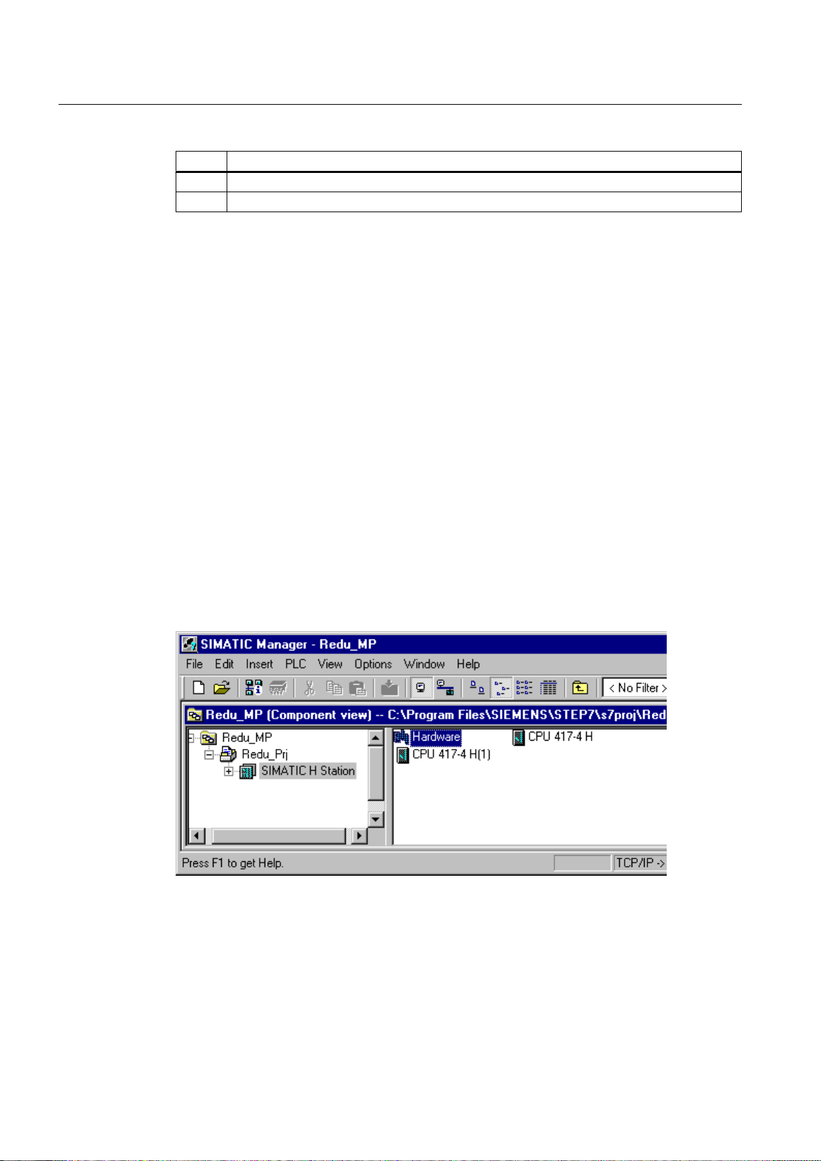
Advantages of fault-tolerant components
4.2 SIMATIC H Station
Step What?
3 Configuring redundant communications processors (Page 93)
4 Setting the CPU for the error response of input/output modules (Page 95)
4.2.2 How to add a SIMATIC H station to your project
Introduction
The SIMATIC H station is contained in the hardware catalog of HW Config as a stand-alone
station type. This station type is required if you want to configure two central racks each with
an H CPU, thereby configuring your process control system with redundancy.
Procedure
1. Open your PCS 7 project in the component view of SIMATIC Manager.
2. Select the menu command View > Component View.
Result
3. Select the project.
4. Select the menu command Insert > Station > SIMATIC H Station.
The configuration in the SIMATIC Manager appears as follows:
Fault-tolerant Process Control Systems (V8.0)
90 Function Manual, 03/2012, A5E02779471-02
Page 91

Additional information
Advantages of fault-tolerant components
4.2 SIMATIC H Station
● Manual
Automation System S7-400H; Fault-tolerant Systems
4.2.3 How to insert synchronization modules into the H CPU
Requirements
● The PCS 7 project is open in SIMATIC Manager.
● HW Config is open.
● The rack has been inserted according to the configuration in HW Config.
● Each rack has been fitted with an H CPU in HW Config.
Procedure
1. In HW Config, select the menu command View > Catalog.
2. In the hardware catalog, double-click the H CPU you are using. Within the active tree view,
double-click on the version of the H CPU you have selected.
The H sync module is located below the version folder, e.g., V4.0.
3. Select the H Sync Module and drag it onto slots "IF1" and "IF2" of each H CPU.
Fault-tolerant Process Control Systems (V8.0)
Function Manual, 03/2012, A5E02779471-02 91
Page 92

Advantages of fault-tolerant components
4.2 SIMATIC H Station
Result
The following figure shows an example of the configured subsystems of the fault-tolerant
station in HW Config:
Additional information
● Documentation
● Manual
92 Function Manual, 03/2012, A5E02779471-02
Automation System S7-400H; Fault-tolerant Systems
Process Control System PCS 7; PCS 7 - Released Modules
Fault-tolerant Process Control Systems (V8.0)
Page 93

Advantages of fault-tolerant components
4.2.4 How to configure redundant communication processors
Introduction
Configure at least one CP 443-1 for each H CPU on a plant bus. You can also make a redundant
interconnection.
Requirements
● The PCS 7 project with a SIMATIC H station is open in SIMATIC Manager.
● HW Config is open.
● The racks for the SIMATIC H station are inserted in HW Config, for example, 2 UR2-H racks.
● In HW Config, each rack has been fitted with an H CPU and the required synchronization
modules.
Procedure
4.2 SIMATIC H Station
1. In the hardware catalog, double-click the "SIMATIC 400" folder. Then double-click the
"CP-400" folder and finally the "Industrial Ethernet" folder.
2. Select the CP you are using and drag it to a free slot on the rack.
Note
Using a communication processor that supports multiple communication protocols
Configure the ISO interface for the "Fault-tolerant S7 connection" in the "Parameters" tab
of the "Properties - Ethernet Interface CP 443-1" dialog box.
Fault-tolerant Process Control Systems (V8.0)
Function Manual, 03/2012, A5E02779471-02 93
Page 94
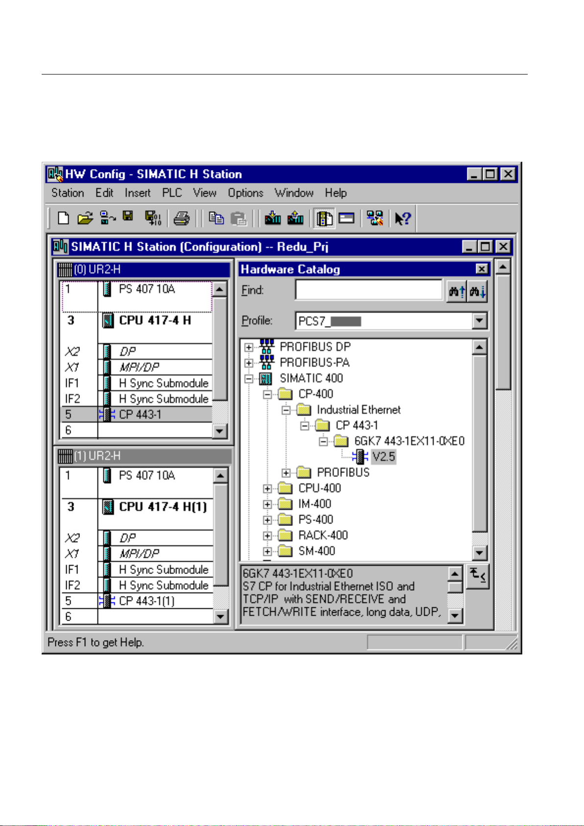
Advantages of fault-tolerant components
4.2 SIMATIC H Station
Result
The following figure shows an example of configuration in HW Config. Connection to a faulttolerant plant bus is possible.
Fault-tolerant Process Control Systems (V8.0)
94 Function Manual, 03/2012, A5E02779471-02
Page 95

Additional information
Advantages of fault-tolerant components
4.2 SIMATIC H Station
● Manual
Automation System S7-400H; Fault-tolerant Systems
4.2.5 How to set the failure reaction of the input/output modules on the CPU
Introduction
Only perform the following procedure when the libraries "Redundant IO (V3.0)" or "Redundant
IO (V4.0)" are used.
As of PCS 7 V7.1, the characteristics of the redundant input/output modules are set for channelbased reaction to channel faults. The function in the AS depends on the employed PCS 7
library and the modules.
Depending on the configured module, the code is automatically generated for the automation
system based on the optimal capabilities of the module.
Passivation reaction of the modules
You will find information on which modules are released for which passivation reaction in the
documentation
Passivation reaction Reaction of the module
Module-based The module is passivated if a fault occurs.
Group-based If a fault occurs in a channel, the group of channels is passivated in
Channel-based Only the channels on which the fault occurred are passivated.
PCS 7 - Released Modules
a module in which a least one fault has occurred.
.
Requirements
● The PCS 7 project is open in SIMATIC Manager.
● An H-CPU is configured in HW Config.
● S7 driver blocks from the "Redundant IO (V3.0)" or "Redundant IO (V4.0)" library
Procedure
1. In the component view, select the SIMATIC H station.
2. Double-click the "Hardware" object in the detail window.
HW Config opens.
3. Select the CPU you are using on slot 3.
4. Select the menu command Edit > Object Properties.
The "Properties - CPU ..." dialog box opens.
5. Select the "H Parameters" tab.
Fault-tolerant Process Control Systems (V8.0)
Function Manual, 03/2012, A5E02779471-02 95
Page 96

Advantages of fault-tolerant components
4.3 Communication connections
6. Please make a note of which data blocks in the "Data block no." input box are defined as
standard transmitters so that you do not use them in your configuration.
7. Select the required setting for the passivation behavior from the "Passivation behavior" list
in the "Redundant I/O" area.
– Module-based when the "Redundant IO (V3.0)" library is used
– Channel-based when the "Redundant IO (V4.0)" library is used
Additional information
● Function manual
Process Control System PCS 7; software update without utilization of new
functions
● Documentation
Process Control System PCS 7; PCS 7 - Released Modules
4.3 Communication connections
4.3.1 Overview of configuration tasks
Introduction
After you have inserted all of the components (AS, OS and ES) in your project, you can use
NetPro to configure the network connections between the SIMATIC components. When the
configuration of the connections and network is complete, the configuration needs to be
compiled, saved and downloaded to the CPU of the automation system.
Downloading connection configurations
Connection configurations can be downloaded to the CPU in RUN mode. To do this, select
the connection to be downloaded in NetPro and transfer it to the CPU by selecting the menu
command Target systems > Download > Selected Connections. Process interfacing for
operation stations is not possible until the connections are made known to the AS.
You need to change the MAC addresses after failure of network adapters. You adapt the
addresses in the properties dialog box of the individual operator stations in NetPro. The
configuration has to be compiled and downloaded in NetPro each time it is changed.
Overview
This section describes the configuration steps for the following topics:
● Configuring a redundant, fault-tolerant terminal bus (Page 97)
● Configuring a fault-tolerant plant bus (Page 100)
● Configuring a redundant PROFIBUS DP (Page 102)
● Configuring a redundant PROFIBUS PA (Page 107)
Fault-tolerant Process Control Systems (V8.0)
96 Function Manual, 03/2012, A5E02779471-02
Page 97

Advantages of fault-tolerant components
4.3 Communication connections
4.3.2 Configuring the connection to the terminal bus
4.3.2.1 How to configure the redundant terminal bus on the basis of the Parallel Redundancy Protocol
Introduction
The NetPro and HW Config programs do not support configuration of the terminal bus. The
"SIMATIC NET SOFTNET-IE RNA" software is used in PCS 7 for the connection of a PC
station to separate redundant networks.
Conditions and rights required
You require the following to be able to install and operate SOFTNET-IE RNA on your PC:
● 2 free Ethernet network adapters
● 2 separate Ethernet networks
● Administrator rights for installation
● Exactly one software license for SOFTNET-IE RNA per PC.
Installation and configuration
Information about the installation process can be found in the
Industrial Ethernet; SOFTNET-IE RNA
operating instructions.
SIMATIC NET; PG/PC -
Additional information
● Readme file for the "SIMATIC NET SOFTNET-IE RNA" software
● You can find additional information on the individual SIMATIC NET products and their
configuration on the Internet (http://www.siemens.com/automation/service&support).
4.3.2.2 How to configure the redundant terminal bus on the basis of the INTEL TEAM mode
Introduction
The NetPro and HW Config programs do not support configuration of the terminal bus. The
PC stations are connected to the redundant terminal bus over network adapters capable of
redundancy.
The section below describes how you install and configure the drivers for network adapters of
these PC stations.
Fault-tolerant Process Control Systems (V8.0)
Function Manual, 03/2012, A5E02779471-02 97
Page 98

Advantages of fault-tolerant components
4.3 Communication connections
Requirements
Each PC station (for example, OS server, OS client, domain controller) connected to the
terminal bus as a redundant component has to meet the following requirements:
● Redundant connection of the PC station to the terminal bus:
Two network adapters working in INTEL Team mode on a PC.
● The driver for the network adapters required for the operating system (32/64 bit) must be
installed. You can find the driver on the "Software_Support_and_Tools" DVD in the folder
Drivers > Network > INTEL.
Network adapters for the redundant terminal bus
PC type Network adapter 1 Network adapter 2 Remark
SIMATIC IPC
● SIMATIC IPC 547D
● SIMATIC IPC 647C
● SIMATIC IPC 847C
SIMATIC IPC 427C
(Microbox)
Suitable PC Intel PRO/1000 PT Server-
Onboard (LM-Adapter) Onboard (L-Adapter) Only on Windows 7/Server
2008 R2
Onboard (LM-Adapter) Onboard (L-Adapter) Only for PCS 7 OS Client
Adapter (EXPI9400PT)
Intel PRO/1000 PT Server-
Adapter (EXPI9400PT)
Intel PRO/1000 MT Server-
Adapter
Intel Gigabit CT DesktopAdapter (EXPI9301CT)
Intel PRO/1000 PT DesktopAdapter (EXPI9300PT
Intel PRO/1000 GT DesktopAdapter
Only on Windows XP/Server
2003
Procedure – installing and configuring drivers
1. Unzip the compressed driver file (Zip).
2. Install the device driver using the autostart file with standard settings.
3. Open the Device Manager > Network adapters.
4. If no onboard network adapters are being used for connecting to the terminal bus, select
the internal network adapter of the PC station and deactivate the internal network adapter
via the shortcut menu.
5. Select the adapter "Network Adapter 1" (see table; INTEL server adapter or LM adapter for
the INTEL onboard network adapters) and select the menu command Settings from the
shortcut menu.
6. In the "Teaming" tab, select the "Team this adapter with other Adapters" check box. Click
"New Team".
The "New Team Wizard" dialog box opens.
7. Enter a name for the team (for example, "TerminalBusTeam #0"). Click "Next".
Fault-tolerant Process Control Systems (V8.0)
98 Function Manual, 03/2012, A5E02779471-02
Page 99

Advantages of fault-tolerant components
4.3 Communication connections
8. In the "Select the adapters to include in this team" list, select the network adapters through
which the computer should be connected to the redundant terminal bus.
– "Network adapter 1" (see table)
– "Network adapter 2" (see table; INTEL Desktop Adapter or L adapter for the INTEL
onboard network adapters)
9. Click "Next".
10.In the "Select a team type" list, select "SFT (Switch fault tolerance)". Click "Next".
11.Click "Finish".
The "New Team Wizard" dialog box closes.
The team ("TerminalBusTeam #0" in the example) is entered in the "Settings" dialog box
of the network adapter.
12.The "Properties of team: <team name>" dialog box opens ("TerminalBusTeam #0" in the
example).
13.Select the "Settings" tab and click "Modify Team...".
14.In the "Adapters" tab, select network adapter 1 on the preferred terminal bus.
Click "Set Primary".
15.Select the "network adapter 2" on the redundant terminal bus. Click "Set Secondary".
16.Click "OK" to confirm the Team dialog boxes.
17.The Team dialog boxes close.
The two network adapters are entered as a team in the Device Manager
(Example: Team: Intel (R) Pro/1000 ...).
18.Open the dialog window "Network connections" ("Change adapter settings") via the control
panel.
19.If the entry "File" is missing in the menu bar, select the menu command Organize > Layout
> Menu bar.
20.Activate the detailed view of the list.
Recommendation: Allocate names to the network adapters (File > Rename)
Example:
– 1. <Team name> <Team> ("TerminalBusTeam #0" in the example)
– 2. <Team name> <Master> ("TerminalBusTeam #0 (Master)" in the example)
– 3. <Team name> <Standby> ("TerminalBusTeam #0 (Standby)" in the example)
21.Check the order of network adapters under "Advanced> "Advanced Settings ...". In the
"Adapters and Connections" tab, the team must be at the top of the list under "Connections":
– 1. <Team name>" (in the example, "TerminalBusTeam #0")
– 2. <Team name> <Master ... Adapter> (INTEL server adapter or LM adapter for INTEL
onboard network adapters)
– 3. <Teamname> <Standby ... Adapter> (INTEL desktop adapter or L adapter for INTEL
onboard network adapters)
22.Click "OK" to close the dialog box.
Fault-tolerant Process Control Systems (V8.0)
Function Manual, 03/2012, A5E02779471-02 99
Page 100

Advantages of fault-tolerant components
4.3 Communication connections
4.3.2.3 How to connect singular components to the redundant terminal bus on the basis of the Parallel Redundancy Protocol
Introduction
You can connect the following non-redundant objects to a redundant network with the
SCALANCE X204RNA .
● Non-redundant networks
● Components that have just one network connection, for example
You will find additional information on this topic in section "Redundant, fault-tolerant terminal
bus based on the Parallel Redundancy Protocol (PRP) (Page 50)".
Procedure
1. Connect the networks for the redundant terminal bus (referred to as LAN A and LAN B
below) to the following ports of the SCALANCE X204RNA :
– PRP A (LAN A)
– PRP B (LAN B)
2. Connect the non-redundant objects to the following ports:
– P1
– P2
3. Configure the SCALANCE X204RNA.
Messages
● SCALANCE X204RNA has signaling contacts.
Additional information about configuration
● Operating instructions
SIMATIC NET; SCALANCE X204RNA, SCALANCE X204RNA EEC
4.3.3 How to configure a fault-tolerant plant bus
Introduction
You configure the communication connections for the plant bus with NetPro. Industrial Ethernet
is used for the plant bus.
Fault-tolerant plant bus
You can set up a fault-tolerant plant bus with a ring structure.
Fault-tolerant Process Control Systems (V8.0)
100 Function Manual, 03/2012, A5E02779471-02
 Loading...