

Page 1

Contents
SIMATIC
SIMATIC PC RI25/45
Technical Description
System Unit
Motherboard
Bus Board
Monitoring Module
Hard Disk Drive
Floppy Disk Drive
CD-ROM Drive
Back-Up Battery
220 V Power Supply
1
2
3
4
5
6
7
8
9
Index
C79000-G7076-C808-01
Page 2

Safety Guidelines
!
!
!
This manual contains notices which you should observe to ensure your own personal safety, as well as
to protect the product and connected equipment. These notices are highlighted in the manual by a
warning triangle and are marked as follows according to the level of danger:
Danger
indicates that death, severe personal injury or substantial property damage will result if proper precautions
are not taken.
Warning
indicates that death, severe personal injury or substantial property damage can result if proper precautions are not taken.
Caution
indicates that minor personal injury or property damage can result if proper precautions are not taken.
Note
draws your attention to particularly important information on the product, handling the product, or to a
particular part of the documentation.
Qualified Personnel
Correct Usage
!
Trademarks
The device/system may only be set up and operated in conjunction with this manual.
Only qualified personnel should be allowed to install and work on this equipment. Qualified persons
are defined as persons who are authorized to commission, to ground, and to tag circuits, equipment,
and systems in accordance with established safety practices and standards.
Note the following:
Warning
This device and its components may only be used for the applications described in the catalog or the
technical description, and only in connection with devices or components from other manufacturers
which have been approved or recommended by Siemens.
This product can only function correctly and safely if it is transported, stored, set up, and installed
correctly , and operated and maintained as recommended.
SIMA TIC R, SIMA TIC NETR and SINECR are registered trademarks of SIEMENS AG.
Third parties using for their own purposes any other names in this document which refer to
trademarks might infringe upon the rights of the trademark owners.
Disclaimer of LiabilityCopyright E Siemens AG 1998 All rights reserved
The reproduction, transmission or use of this document or its contents is
not permitted without express written authority. Of fenders will be liable for
damages. All rights, including rights created by patent grant or registration
of a utility model or design, are reserved.
Siemens AG
Bereich Automatisierungs- und Antriebstechnik
Geschaeftsgebiet Industrie-Automatisierungssysteme
Postfach 4848, D-90327 Nuernberg
Siemens Aktiengesellschaft C79000-G7076-C808
We have checked the contents of this manual for agreement with the
hardware and software described. Since deviations cannot be precluded
entirely , we cannot guarantee full agreement. However , the data in this
manual are reviewed regularly and any necessary corrections included in
subsequent editions. Suggestions for improvement are welcomed.
Subject to change without prior notice
E Siemens AG 1998
Page 3

Contents
1 System Unit 1-1. . . . . . . . . . . . . . . . . . . . . . . . . . . . . . . . . . . . . . . . . . . . . . . . . . . . . . . . . . . .
1.1 Dimensions of Expansion Modules 1-2. . . . . . . . . . . . . . . . . . . . . . . . . . . . . . . . .
1.2 Power Requirements of the Components (Maximum Values) 1-4. . . . . . . . . .
1.3 Removing and Installing Components 1-5. . . . . . . . . . . . . . . . . . . . . . . . . . . . . .
1.3.1 Changing the Air Filter 1-7. . . . . . . . . . . . . . . . . . . . . . . . . . . . . . . . . . . . . . . . . . .
1.3.2 Removing the Protective Sliding Cover 1-7. . . . . . . . . . . . . . . . . . . . . . . . . . . . .
1.3.3 Opening the System Unit 1-8. . . . . . . . . . . . . . . . . . . . . . . . . . . . . . . . . . . . . . . . .
1.3.4 Removing and Installing Fans 1-9. . . . . . . . . . . . . . . . . . . . . . . . . . . . . . . . . . . . .
1.3.5 Removing and Installing the 3.5” Floppy Disk Drive 1-10. . . . . . . . . . . . . . . . . .
1.3.6 Removing and Installing the Drive Block (Front) 1-11. . . . . . . . . . . . . . . . . . . . .
1.3.7 Removing and Installing Hard Disk Drives (Back) 1-12. . . . . . . . . . . . . . . . . . . .
1.3.8 Removing and Installing the Display Board 1-13. . . . . . . . . . . . . . . . . . . . . . . . . .
1.3.9 Removing and Installing Module Retainers (only RI45/RI45PCS) 1-14. . . . . . .
1.3.10 Removing and Installing Expansion Modules 1-15. . . . . . . . . . . . . . . . . . . . . . . .
1.3.11 Removing and Installing the Bus Board 1-15. . . . . . . . . . . . . . . . . . . . . . . . . . . . .
1.3.12 Removing and Installing the CPU Board 1-16. . . . . . . . . . . . . . . . . . . . . . . . . . . .
1.3.13 Connecting the Multipoint Interface (MPI/DP) 1-17. . . . . . . . . . . . . . . . . . . . . . .
1.4 Error Diagnostics 1-18. . . . . . . . . . . . . . . . . . . . . . . . . . . . . . . . . . . . . . . . . . . . . . . .
2 Motherboard 2-1. . . . . . . . . . . . . . . . . . . . . . . . . . . . . . . . . . . . . . . . . . . . . . . . . . . . . . . . . . .
2.1 Components 2-2. . . . . . . . . . . . . . . . . . . . . . . . . . . . . . . . . . . . . . . . . . . . . . . . . . . .
2.2 Processor 2-3. . . . . . . . . . . . . . . . . . . . . . . . . . . . . . . . . . . . . . . . . . . . . . . . . . . . . .
2.3 Cache Modules 2-4. . . . . . . . . . . . . . . . . . . . . . . . . . . . . . . . . . . . . . . . . . . . . . . . .
2.4 Graphics Interface Module 2-5. . . . . . . . . . . . . . . . . . . . . . . . . . . . . . . . . . . . . . . .
2.5 Memory 2-8. . . . . . . . . . . . . . . . . . . . . . . . . . . . . . . . . . . . . . . . . . . . . . . . . . . . . . . .
2.6 Changing the Backup Battery 2-11. . . . . . . . . . . . . . . . . . . . . . . . . . . . . . . . . . . . .
2.7 Block Diagram of the Motherboard 2-12. . . . . . . . . . . . . . . . . . . . . . . . . . . . . . . . .
2.8 Hardware Ports 2-13. . . . . . . . . . . . . . . . . . . . . . . . . . . . . . . . . . . . . . . . . . . . . . . . .
2.9 Hardware Addresses 2-26. . . . . . . . . . . . . . . . . . . . . . . . . . . . . . . . . . . . . . . . . . . .
2.10 Interrupt and DMA Assignments 2-30. . . . . . . . . . . . . . . . . . . . . . . . . . . . . . . . . . .
2.1 1 Setup 2-31. . . . . . . . . . . . . . . . . . . . . . . . . . . . . . . . . . . . . . . . . . . . . . . . . . . . . . . . . .
2.11.1 Main Menu 2-35. . . . . . . . . . . . . . . . . . . . . . . . . . . . . . . . . . . . . . . . . . . . . . . . . . . . .
2.11.2 Advanced Menu 2-44. . . . . . . . . . . . . . . . . . . . . . . . . . . . . . . . . . . . . . . . . . . . . . . . .
2.11.3 Security Menu 2-46. . . . . . . . . . . . . . . . . . . . . . . . . . . . . . . . . . . . . . . . . . . . . . . . . .
2.11.4 Power Menu 2-47. . . . . . . . . . . . . . . . . . . . . . . . . . . . . . . . . . . . . . . . . . . . . . . . . . . .
2.11.5 Exit Menu 2-49. . . . . . . . . . . . . . . . . . . . . . . . . . . . . . . . . . . . . . . . . . . . . . . . . . . . . .
2.12 Diagnostic Messages (Port 80) 2-51. . . . . . . . . . . . . . . . . . . . . . . . . . . . . . . . . . . .
SIMA TIC PC RI25/45, Technical Description
C79000-G7076-C808-01
iii
Page 4

Contents
3 Bus Board/Operator Panel 3-1. . . . . . . . . . . . . . . . . . . . . . . . . . . . . . . . . . . . . . . . . . . . . .
3.1 Technical Specifications 3-2. . . . . . . . . . . . . . . . . . . . . . . . . . . . . . . . . . . . . . . . . .
3.2 Installation and Functional Specifications 3-2. . . . . . . . . . . . . . . . . . . . . . . . . . .
3.2.1 Power Supply Connection 3-3. . . . . . . . . . . . . . . . . . . . . . . . . . . . . . . . . . . . . . . .
3.2.2 Power-Good-Signal 3-5. . . . . . . . . . . . . . . . . . . . . . . . . . . . . . . . . . . . . . . . . . . . . .
3.2.3 Fan Connector P405, P407 3-6. . . . . . . . . . . . . . . . . . . . . . . . . . . . . . . . . . . . . . .
3.2.4 IDSEL Setting for PCI Slots 3-6. . . . . . . . . . . . . . . . . . . . . . . . . . . . . . . . . . . . . . .
3.3 Operator Panel 3-7. . . . . . . . . . . . . . . . . . . . . . . . . . . . . . . . . . . . . . . . . . . . . . . . .
3.4 Operator Panel for SafeCard 3-8. . . . . . . . . . . . . . . . . . . . . . . . . . . . . . . . . . . . . .
4 Monitoring Module 4-1. . . . . . . . . . . . . . . . . . . . . . . . . . . . . . . . . . . . . . . . . . . . . . . . . . . . .
4.1 Overview 4-2. . . . . . . . . . . . . . . . . . . . . . . . . . . . . . . . . . . . . . . . . . . . . . . . . . . . . . .
4.2 Status and Diagnostic Displays 4-5. . . . . . . . . . . . . . . . . . . . . . . . . . . . . . . . . . . .
4.3 Temperature Monitoring / Display and Fan Control 4-6. . . . . . . . . . . . . . . . . . .
4.4 Watchdog (WD) 4-7. . . . . . . . . . . . . . . . . . . . . . . . . . . . . . . . . . . . . . . . . . . . . . . . .
4.5 Relay Output 4-9. . . . . . . . . . . . . . . . . . . . . . . . . . . . . . . . . . . . . . . . . . . . . . . . . . .
4.6 Battery-Backed RAM (optional) 4-10. . . . . . . . . . . . . . . . . . . . . . . . . . . . . . . . . . . .
4.7 Software Interfaces 4-11. . . . . . . . . . . . . . . . . . . . . . . . . . . . . . . . . . . . . . . . . . . . . .
4.8 Hardware Ports 4-14. . . . . . . . . . . . . . . . . . . . . . . . . . . . . . . . . . . . . . . . . . . . . . . . .
5 Hard Disk Drive 5-1. . . . . . . . . . . . . . . . . . . . . . . . . . . . . . . . . . . . . . . . . . . . . . . . . . . . . . . . .
5.1 Technical Specifications 5-2. . . . . . . . . . . . . . . . . . . . . . . . . . . . . . . . . . . . . . . . . .
6 Floppy Disk Drive 6-1. . . . . . . . . . . . . . . . . . . . . . . . . . . . . . . . . . . . . . . . . . . . . . . . . . . . . .
6.1 Technical Specifications 6-2. . . . . . . . . . . . . . . . . . . . . . . . . . . . . . . . . . . . . . . . . .
7 CD-ROM Drive 7-1. . . . . . . . . . . . . . . . . . . . . . . . . . . . . . . . . . . . . . . . . . . . . . . . . . . . . . . . . .
7.1 CD-ROM Drive 7-2. . . . . . . . . . . . . . . . . . . . . . . . . . . . . . . . . . . . . . . . . . . . . . . . . .
8 Back-Up Battery 8-1. . . . . . . . . . . . . . . . . . . . . . . . . . . . . . . . . . . . . . . . . . . . . . . . . . . . . . . .
8.1 Back-Up Battery 8-2. . . . . . . . . . . . . . . . . . . . . . . . . . . . . . . . . . . . . . . . . . . . . . . .
9 220 V Power Supply 9-1. . . . . . . . . . . . . . . . . . . . . . . . . . . . . . . . . . . . . . . . . . . . . . . . . . . .
9.1 Technical Specifications 9-2. . . . . . . . . . . . . . . . . . . . . . . . . . . . . . . . . . . . . . . . . .
Index Index-1. . . . . . . . . . . . . . . . . . . . . . . . . . . . . . . . . . . . . . . . . . . . . . . . . . . . . . . . . . . . .
iv
SIMA TIC PC RI25/45, Technical Description
C79000-G7076-C808-01
Page 5

System Unit
1
Chapter
Overview
Section Description Page
1.1 Dimensions of Expansion Modules 1-2
1.2 Power Requirements of the Components (Maximum
V alues)
1.3 Removing and Installing Components 1-5
1.3.1 Changing the Air Filter 1-7
1.3.2 Removing the Protective Sliding Cover 1-7
1.3.3 Opening the System Unit 1-8
1.3.4 Removing and Installing Fans 1-9
1.3.5 Removing and Installing the 3.5” Floppy Disk Drive 1-10
1.3.6 Removing and Installing the Drive Block (Front) 1-1 1
1.3.7 Removing and Installing Hard Disk Drives (Back) 1-12
1.3.8 Removing and Installing the Display Board 1-13
1.3.9 Removing and Installing Module Retainers (only
RI45/RI45PCS)
1.3.10 Removing and Installing Expansion Modules 1-15
1.3.11 Removing and Installing the Bus Board 1-15
1.3.12 Removing and Installing the CPU Board 1-16
1.3.13 Connecting the Multipoint Interface (MPI/DP) 1-17
1.4 Error Diagnostics 1-18
1-4
1-14
SIMA TIC PC RI25/45, Technical Description
C79000-G7076-C808-01
1-1
Page 6
System Unit
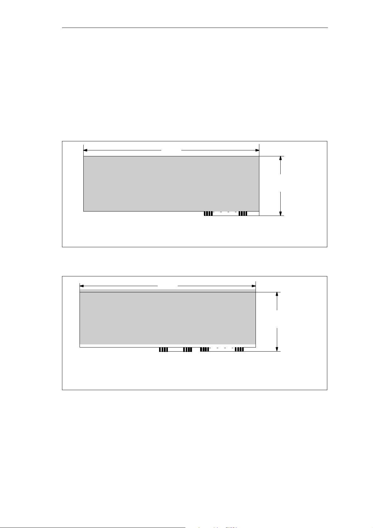
1.1 Dimensions of Expansion Modules
Information on
Modules
(All dimensions in mm)
Figure 1-1 XT module
The SIMATIC PC RI25/45 is designed for modules according to AT/PCI
specifications. The size of the modules should not exceed the dimensions
indicated. If the given height is exceeded, this may cause contacting
problems, functional disorders or difficulties with installation. The figures
below illustrate two cards with full AT/PCI overall length. Individual slots
may require different card dimensions.
340.7
106.7
A31 A1
(All dimensions in mm)
Figure 1-2 AT module
340.7
C18 C1
121.92
A31 A1
1-2
SIMA TIC PC RI25/45, Technical Description
C79000-G7076-C808-01
Page 7
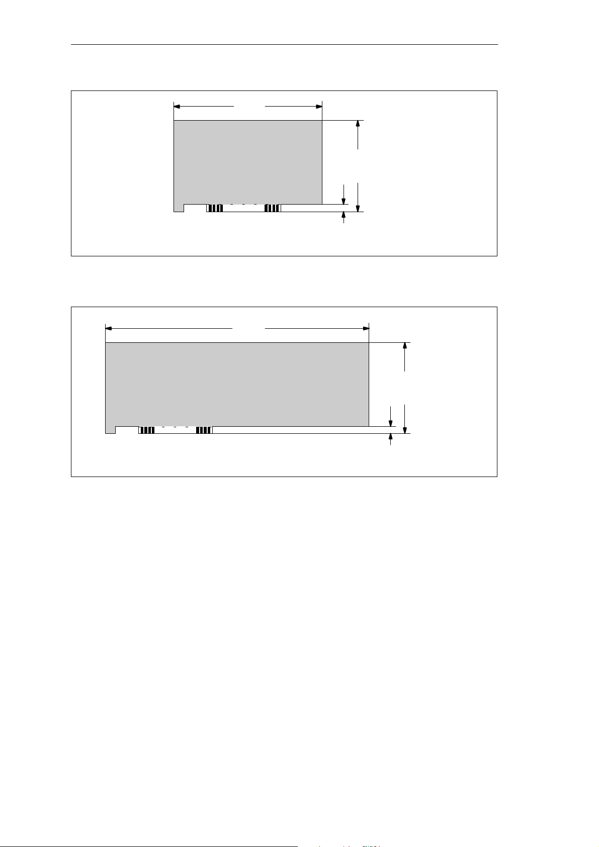
(All dimensions in mm)
Figure 1-3 Small PCI module (5 V)
System Unit
174.63
106.68
8.19
312
(All dimensions in mm)
Figure 1-4 Large PCI module (5 V)
Information on
Large PCI Modules
Large PCI modules have to be equipped with a so-called extender (usually
included with large PCI modules) which serves to guide them along the rails
of the ventilator case. The extender guides large PCI modules along the rails
of ISA modules.
106.68
8.19
SIMA TIC PC RI25/45, Technical Description
C79000-G7076-C808-01
1-3
Page 8
System Unit
1.2 Power Requirements of the Components (Maximum Values)
Basic System
Restrictions on
Power Supply
Component + 5V – 5V + 12V – 12V
Motherboard 5.1 A 0.01 A 0.1 A 0.02 A
SafeCard monitoring module 0.35 A – 0.03A –
Front fan 0.5 A
3.5” floppy disk drive *)
Hard disk *)
*) see Section 5.1
Due to thermal stress, the maximum capacity of the power supply is
restricted to:
Power supply Restriction
Standard power supply (220 V) maximum load 160 W
1-4
SIMA TIC PC RI25/45, Technical Description
C79000-G7076-C808-01
Page 9
1.3 Removing and Installing Components
System Unit
Prerequisites
!
!
The system unit is designed to enable any necessary maintenance work to be
carried out quickly and at low cost.
Warning
Please read the warnings at the front of the User’s Guide before you open the
housing of the system unit.
Do not open the housing unless you need to install or remove
components, or to replace the battery.
Write down your configuration parameters.
Disconnect the unit from the power supply by unplugging the power plug.
Caution
Risk of damage to the unit!
Note that only qualified personnel should be allowed to work on the open unit,
so the warranty on the device is not affected. Authorized Siemens maintenance
and repair centers offer you a specialist maintenance service. The User’s Guide
contains the addresses.
!
Limitation of
Liability
Caution
The electronic components of the printed boards are extremely sensitive to
electrostatic discharge. When handling the boards, you must follow the
guidelines for electrostatically sensitive components (ESD guidelines) at the
end of this manual.
All technical specifications and licenses apply only to expansion functions
approved by SIEMENS. No liability can be assumed for functional
constraints caused by the use of devices and components of other
manufacturers.
All modules and components in the PC are electrostatically sensitive. Please
read the ESD guidelines. The following sign warns that electrostatically
sensitive modules are present.
SIMA TIC PC RI25/45, Technical Description
C79000-G7076-C808-01
1-5
Page 10

System Unit
Before Opening
the Unit
Tools
The following rules are mandatory when carrying out any work on the open
unit, and should be read carefully before opening the unit:
Before you disconnect the power supply cable, discharge any electrostatic
charge on your body. You can do this by touching metallic parts, such as
screws, on the rear panel of the PC.
Discharge any electrostatic charge from tools that you are using.
Wear a grounding wrist strap if you are handling components.
Leave components and modules in their packing until you are ready to
install them.
Disconnect the PC from its power supply before plugging in or removing
any modules or components.
Touch components and modules only on their edges. Above all, do not
touch the connecting pins and printed conductors.
Do not operate the PC with the cover open.
Use a suitable Philips or Torx screwdriver to remove or install components.
1-6
SIMA TIC PC RI25/45, Technical Description
C79000-G7076-C808-01
Page 11

1.3.1 Changing the Air Filter
System Unit
Important
Information
Note the following steps while replacing the air filter:
The protective cover has to be locked completely (snapped in place on the
right side).
The fan cover can be lifted off (there is no need to remove the cover of the
system unit); it is simply snapped in place.
The air filter is not attached to anything and can easily be removed.
Fan cover
Operator panel
Figure 1-5 Bedienelemente des SIMA TIC PC RI
Status display
LEDs
Reset key
Lock
The protective grid can also be removed, but you will have to use a little
force. Since the filter is replaced while the PC is operating, the protective
grid protects you from injuring yourself on the sharp edges of the fan and
prevents the filter pad from being sucked into the fan.
Caution
!
When the fans are operating, particles can be drawn into the system unit.
The protective grid may only be removed with the PC switched off.
1.3.2 Removing the Protective Sliding Cover
Notes
Please note the following if the protective cover has to be removed:
When the fan cover is in place, the protective cover can only be moved to
the left as far as it will go. In this position, in case you forgot to move the
protective sliding cover back, a limited amount of air can still be drawn in.
If you first removed the fan cover you can slide the cover completely off its
guides.
If the protective sliding cover is completely closed (all the way to the right),
access to drives can be prevented.
SIMA TIC PC RI25/45, Technical Description
C79000-G7076-C808-01
1-7
Page 12
System Unit
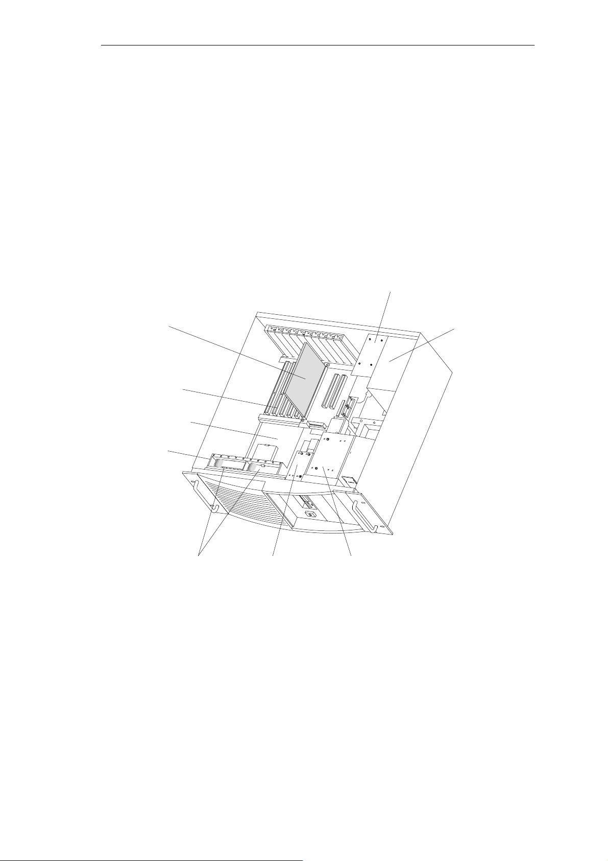
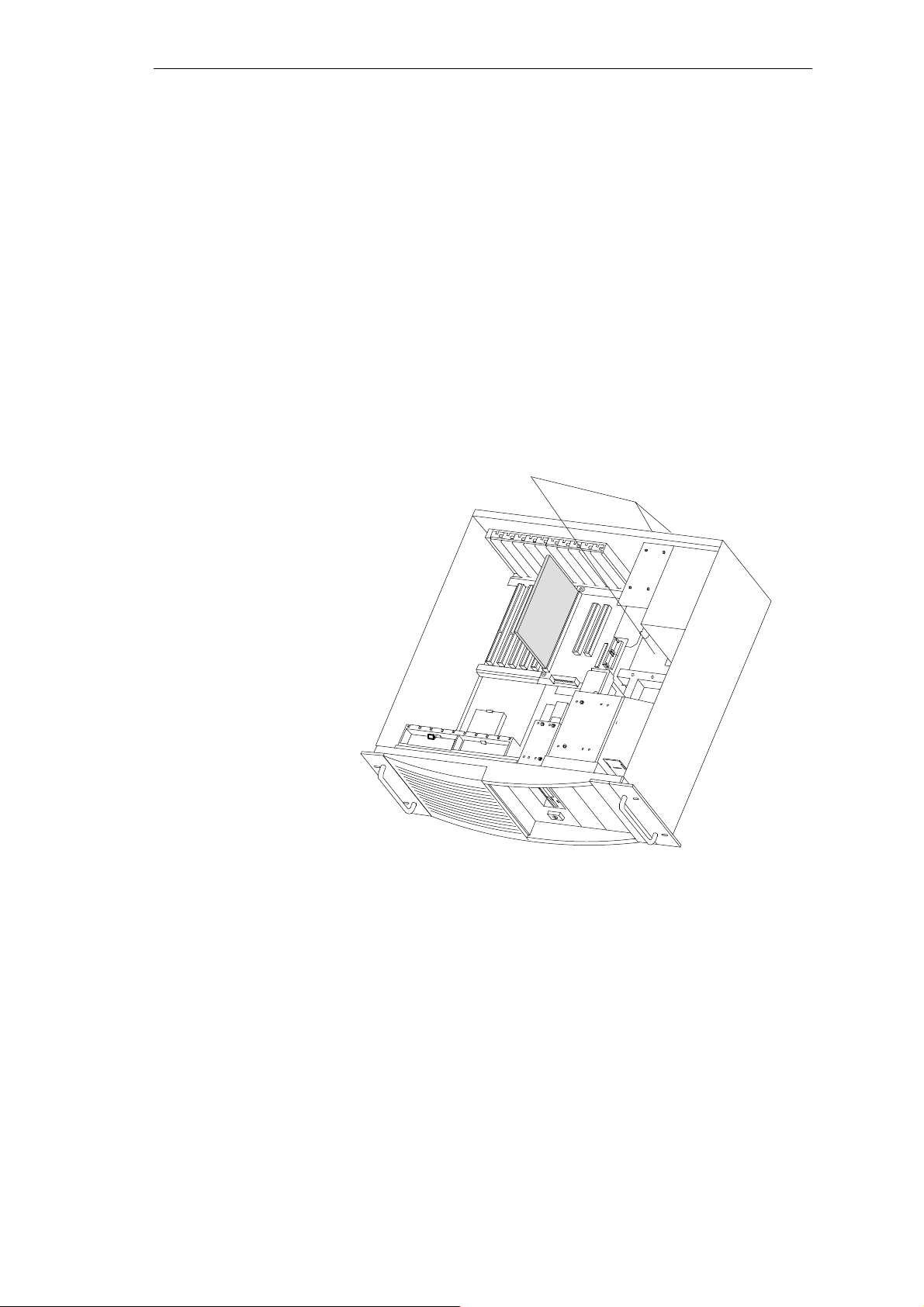
1.3.3 Opening the System Unit
Overview of the
Functional Units
Safe Card
Bus board
Motherboard
Figure 1-6 illustrates the arrangement of units in the open housing of the system
unit:
– motherboard together with with bus module
– SafeCard monitoring module (optional)
– 3.5” floppy disk drive and hard disk drive
– power supply
– fan cage with two fans
Rear support for
hard disk drives
(only with RI45)
Power supply
Fan cage
Two fans 3.5” floppy disk drive
Represented without crossbeam with retainers
Figure 1-6 SIMATIC PC RI
Opening the
System Unit
First remove the screws at the top. Hold the cover at its front left and right
edges, lift it up and off by sliding it back a little.
Front drive block
1-8
SIMA TIC PC RI25/45, Technical Description
C79000-G7076-C808-01
Page 13
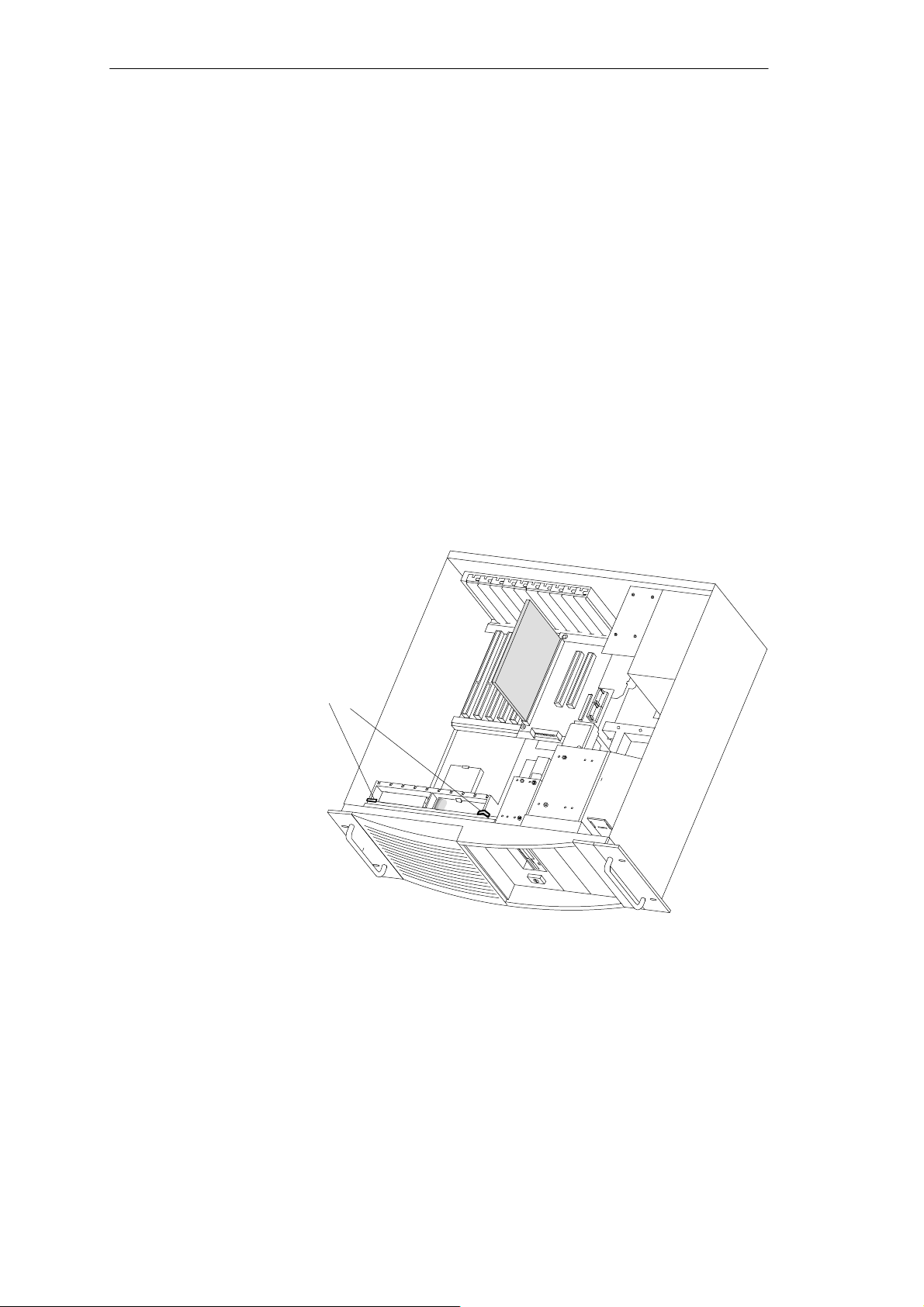
1.3.4 Removing and Installing Fans
System Unit
Procedure
Proceed as follows to remove or install the fan:
Disconnect the cables from the monitoring module, the motherboard, and the
bus module and write down their previous connections.
Provided expansion modules are not installed or have previously been
removed, the fan cage can be taken out. First remove the two clamps of the
fan cage (see Figure 1-7) then push the top of the two side sections outward
and lift the fan cage up.
First the connecting cables have to be carefully removed from the bottom of
the cut-out, then remove the two fans.
If expansion modules are installed, you can take out the fans from the fan
cage, even without previously removing the expansion modules: first unplug
the connecting cable from the fan, then push the hook slightly backwards
(use a screwdriver), and lift up the fan.
Proceed in reverse order to install the fans.
Clamps
Figure 1-7 Removing the fan cage
SIMA TIC PC RI25/45, Technical Description
C79000-G7076-C808-01
1-9
Page 14
System Unit
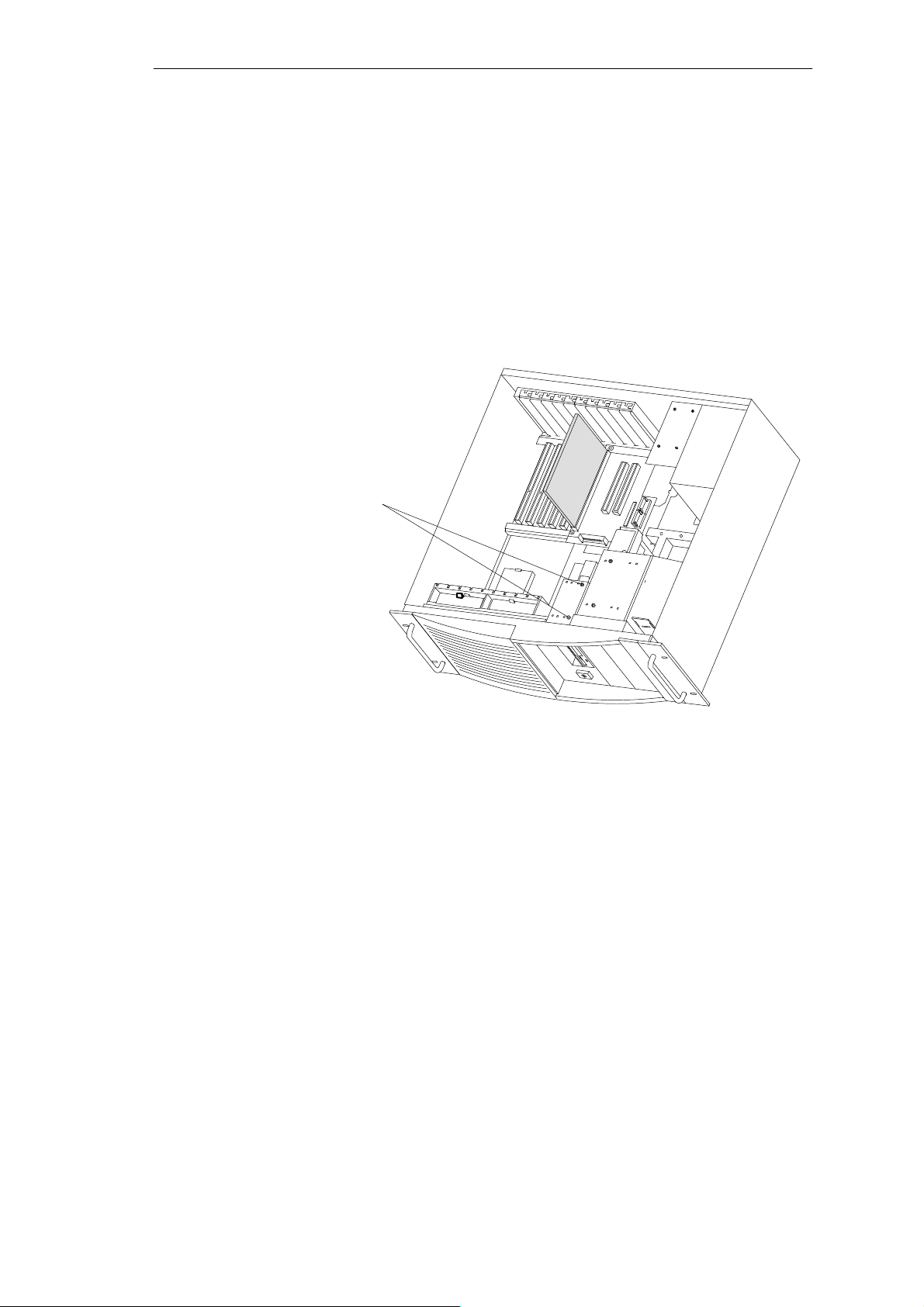
1.3.5 Removing and Installing the 3.5” Floppy Disk Drive
Procedure
Proceed as follows to replace the floppy disk drive:
Disconnect all the cables and write down their prevoius connections.
Release the two screws at the top of the drive support (see arrows in
Figure 1-8) and pull out the drive from the back.
Mounting screws
1-10
Figure 1-8 Removing the floppy disk drive
Proceed in reverse order to install a floppy disk drive.
SIMA TIC PC RI25/45, Technical Description
C79000-G7076-C808-01
Page 15
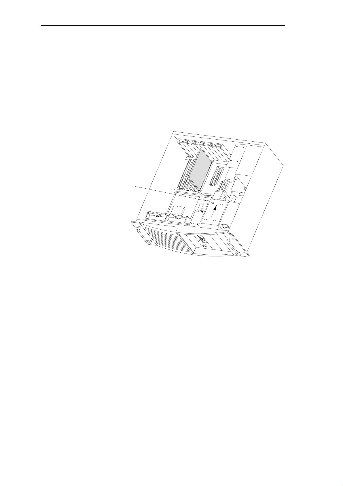
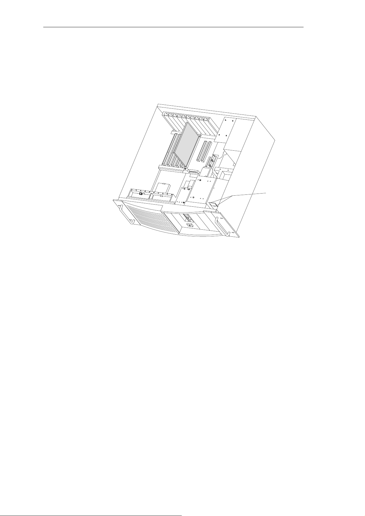
1.3.6 Removing and Installing the Drive Block (Front)
System Unit
Procedure
Proceed as follows to replace the drive block:
Release the screw on the bottom of the housing (do not unscrew it
completely).
Mounting screw
Figure 1-9 Mounting the front drive block
First pull the drive block two centimeters (0.8 inches) to the rear (see
direction of arrow in Figure 1-9) then pull the front block out of the housing.
To replace the drive, or to install a second drive (for example, a CD-ROM
drive), release the two upper and the two lower screws.
Then remove the 3.5” support which lodges the hard disk drive and release
the four screws which connect hard disk drive and support.
5.25” drives or CD-ROM drives do not require any support.
To install the drive block, proceed in reverse order .
SIMA TIC PC RI25/45, Technical Description
C79000-G7076-C808-01
1-11
Page 16
System Unit
1.3.7 Removing and Installing Hard Disk Drives (Back)
Procedure
Proceed as follows to replace or install hard drives:
You can install up to two additional hard disk drives in the support located
at the back of your PC.
The support is mounted with three screws (see Figure 1-10). Two of them are
directly accessible at the back of the system unit. The third screw can only
be reached inside the unit from the top. The hard disk drives must be fixed
with screws at the upper and lower end of the support.
Then connect the installed hard disk drives, CPU board and power supply
by plugging in the corresponding connecting cables.
Mounting screws
1-12
Figure 1-10 Removing and installing hard disk drives
SIMA TIC PC RI25/45, Technical Description
C79000-G7076-C808-01
Page 17
1.3.8 Removing and Installing the Display Board
First disconnect the cables and write down the previous connections.
Then pry the display board out of the catches (see Figure 1-11).
System Unit
Catches
Figure 1-11 Removing the display board
After unscrewing (two hexagonal socket screws) the right handle and the
front plate, the panel covering can be taken off.
SIMA TIC PC RI25/45, Technical Description
C79000-G7076-C808-01
1-13
Page 18
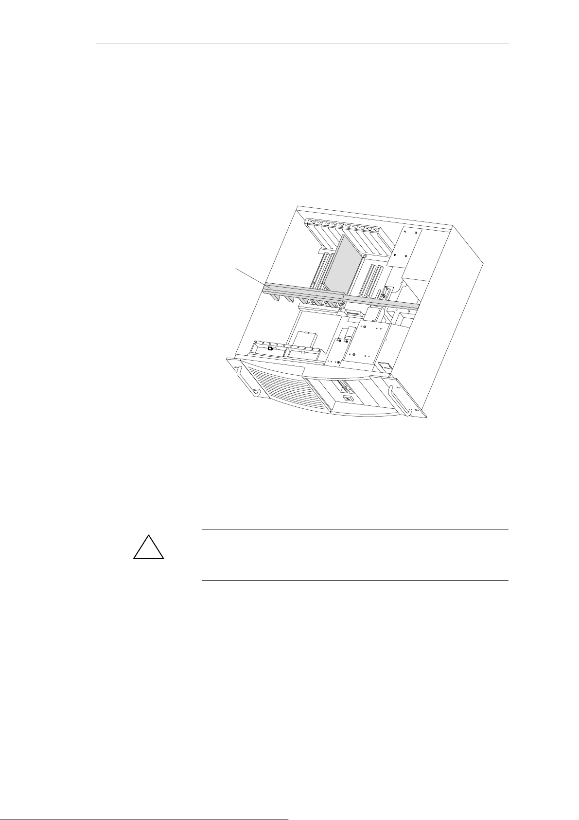
System Unit
1.3.9 Removing and Installing Module Retainers (only RI45/RI45PCS)
First remove the crossbeam on which the modules are mounted.
Bend the two notched spring clips slightly inwards to release the snap-in
lockings.
Grip the crossbeam and push it about 1 centimeter (half an inch)
backward and then lift it out with the retainers.
Retainer
Figure 1-12 Module retainers and crossbeam
Proceed in reverse order to install the retainers.
Adjusting retainers:
Insert the sliding element at the top and push it down until it covers the
module. Then guide the module into the notch.
Caution
!
Do not exert pressure on the module. This means that you should not push
down or force the retainers in any way.
Cut off the part of the sliding element that sticks out as described below:
– Scratch a notch in the top of the sliding element on the upper edge of
the retainer using a knife and bend it over to break it off.
– Cut off any leftover part using a sharp side cutter or a hacksaw.
1-14
SIMA TIC PC RI25/45, Technical Description
C79000-G7076-C808-01
Page 19

1.3.10 Removing and Installing Expansion Modules
Disconnect all connectors. Write down previous connections.
Release the screw which mounts the modules on the back of the system
unit.
Carefully remove the module without bending it.
To install the new module, proceed in reverse order.
1.3.11 Removing and Installing the Bus Board
First remove all expansion modules.
Disconnect all connectiong cables or connectors and write down their
previous connections.
Release 5 screws (2 at the front with the spacer between the CPU board
and 3 screws at the back).
System Unit
Lift the bus board out of the connector to the CPU board.
To install a new board, proceed in reverse order.
SIMA TIC PC RI25/45, Technical Description
C79000-G7076-C808-01
1-15
Page 20
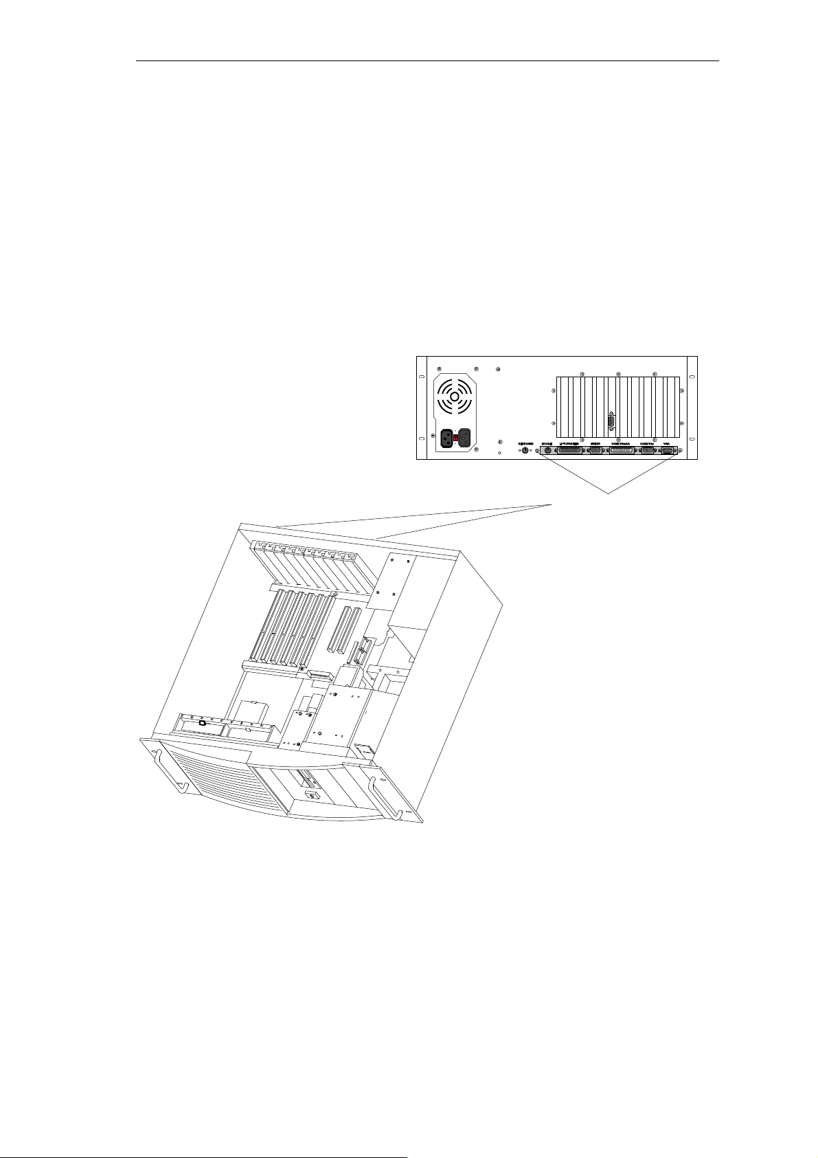
System Unit
1.3.12 Removing and Installing the CPU Board
Remove module supports (only RI45/RI45PCS)
Remove all expansion modules and slot plates.
Disconnect all cables from the CPU board and the bus board and write
down their previous connections.
Release the 2 screws at the back of the system unit (see arrows in
Figure 1-13), then push forward the CPU board and its baseplate until it
comes to a stop and lift it out. You can now remove the bus board if
necessary.
Figure 1-13 Removing the CPU board
To install the board, follow the instructions in reverse order.
The bus board and supporting plate are not included with the CPU board
when supplied as a spare part.
Mounting screws
1-16
SIMA TIC PC RI25/45, Technical Description
C79000-G7076-C808-01
Page 21

1.3.13 Connecting the Multipoint Interface (MPI/DP)
System Unit
Connecting a
PROFIBUS-DP
Network via
MPI /DP Interface
!
You can connect youR IPC to a PROFIBUS-DP network via the optically
isolated* MPI/DP interface. The connection is established via any stationary
connecting PROFIBUS components or via an MPI connecting cable (5 m)
(Order No.: 6ES7001-0BF00-0AA0). The PROFIBUS components and MPI
connecting cable are not included with the IPC and have to be ordered
separately. The MPI connecting cable (5 m) can only be employed for data
transfer rates up to 187.5 Kbps.
You connect your IPC to a PROFIBUS-DP network as follows:
1. Switch off your IPC.
2. Plug the connecting cable (of the PROFIBUS components or MPI
connecting cable) into the MPI/DP socket of your IPC and tighten the
connector by means of screw-type locking.
3. Switch on your IPC.
Caution
Risk of damage to the unit!
Before plugging in the connecting cables, you must discharge the
electrostatic charge of the cables and of your body by briefly touching a
grounded object (ESD guidelines).
PROFIBUS-DP
Network
You can network up to 32 devices (PC, programming device, programmable
logic controller, or DP components) via the MPI/DP interface in one segment. The interconnection to the PROFIBUS-DP segments is established via
an optically isolated* RS 458 port, which is part of the interface.
You can interconnect several PROFIBUS-DP segments via a repeater.
The entire PROFIBUS-DP network has a maximum capacity of 127 stations.
The data transfer rate of the MPI network is 187.5 Kbps. The data transfer
rate that can be achieved via the MPI/DP interface in the PROFIBUS-DP
network ranges from 9.6 Kbps up to 1.5 Mbps.
Note
For further information on configuring a PROFIBUS-DP network, please
refer to the “S7-300 Programmable Controller, Hardware and Installation”
manual, Order No.: 6ES7030-0AA00-8BA0.
*Optically isolated within safety extra-low voltage circuit (SELV)
SIMA TIC PC RI25/45, Technical Description
C79000-G7076-C808-01
1-17
Page 22

System Unit
1.4 Error Diagnostics
T able 1-1 Errors/faults in IPC operation
Error/Fault
Power-ON LED does not light up PC is switched off
Cause Remedy
Power supply is not properly
connected
The message “Invalid configuration
information... Press the F1 key for
continue, F2 to run SETUP utility”
appears on the screen
The “No boot device available”
appears on the screen
Incorrect configuration data
Backup battery is low or
defective
Diskette in drive A: is not a boot
diskette
Wrong hard disk type entered in
SETUP
“Keyboard stuck; key failure”
message
Booting of the PC aborted after
several beeps
Every time a key is pressed, a beep is
heard and no characters appear
Not-ready message when trying to
write to a diskette
Write-protect error when trying to
write to a diskette
“EPROM TSR interface disabled,
check Power Management” message
A key has become blocked
during the system keyboard
self-test
An error has occured during the
system self-test
Keyboard buffer overflow <CTRL> <PAUSE>
No diskette has been inserted
Diskette has not been formatted
Diskette write-protect activated
Write-protect hole open on 3.5”
diskette
“Programming Interface” has
been disabled in SETUP
Switch on the PC
Check the power supply
connections, power cable, and
power plug
Press the “F2” key, check the
configuration data in SETUP ,
enter any default values, and
check error messages in the first
SETUP menu.
Use the “Fixed disk function” in
SETUP
Check the keyboard
Restart the system
Check the hardware
Insert diskette
Format diskette
Cancel write protection
Enable “Programming
Interface” in SETUP under
submenu “RI Hardware options”
COM 1, COM 2, LPT 1 or MPI do
not respond
< / > key labeling missing No original keyboard German keyboard: <ALTGR>
Ports have been disabled in
SETUP
Enable COM 1, COM 2, LPT 1
or MPI in SETUP under
submenu “RI Hardware
Options”
<ß> or <AL T> <9> <2>
International keyboard:
<AL T> <9> <2>
< / > key is not displayed Wrong keyboard driver is being
used
Mouse not working Trackball will not rotate
No or wrong mouse driver is
being used
Mouse pointer cannot be moved PS/2 port has been disabled in
SETUP
Mouse pointer moving erratically Trackball dirty Clean trackball and housing
Drive cover cannot be opened Filter cap not properly fixed Push filter cap into correct
1-18
Load correct keyboard driver
<ALT> <9> <2>
Clean trackball and housing
Load the right mouse driver
Check SETUP settings
position
SIMA TIC PC RI25/45, Technical Description
C79000-G7076-C808-01
Page 23

Motherboard
2
Chapter
Overview
Section Description Page
2.1 Components 2-2
2.2 Processor 2-3
2.3 Cache Modules 2-4
2.4 Graphics Interface Module 2-5
2.5 Memory 2-8
2.6 Changing the Backup Battery 2-11
2.7 Block Diagram of the Motherboard 2-12
2.8 Hardware Ports 2-13
2.9 Hardware Addresses 2-26
2.10 Interrupt and DMA Assignments 2-30
2.1 1 Setup 2-31
2.1 1.1 Main Menu 2-35
2.1 1.2 Advanced Menu 2-44
2.11.3 Security Menu 2-46
2.1 1.4 Power Menu 2-47
2.1 1.5 Exit Menu 2-49
2.12 Diagnostic Messages (Port 80) 2-51
SIMA TIC PC RI25/45, Technical Description
C79000-G7076-C808-01
2-1
Page 24

Motherboard
2.1 Components
Performance
Characteristics
The following table lists the components of the motherboard and their
characteristics:
Components Performance characteristics
Processor Pentium 75/90/100/120/133 MHZ with integrated cooling unit in ZIF socket
Prepared for Pentium 150/166/200 MHZ
Processor upgrade Socket 7
RI25/45PCS cache
RI45 cache
Memory 64 Bit, 4 SIMM sockets, uni/bilateral, Fast Page Mode or Extended Data Out (EDO).
EPROM 128kB flash
CMOS 114 Byte CMOS RAM with battery backup
Chipset Intel Triton Chipset, NSC Super I/O PC87306
Graphics card SVGA-LCD controller Cirrus GD7543 with Windows accelerator on PCI bus, 1MB
IDE PCI bus, EIDE interface with IO mode 4 for max. 4 drives
Floppy disk drive 2 drives 1.44 or 2.88 MBytes
Expansion slots 6 ISA (full length)
Keyboard DIN port with adapter cable for PS2 keyboard, keyboards with integrated trackball
Mouse PS2 mouse port
Serial port 2 x V24 ports
Parallel port Standard, EPP, and ECP mode
MPI Multipoint interface for SIMA TIC S7
The cache module is optionally synchronous 256 kB/512 kB or asynchronous
(COACH compatible)
256 KB synchronous burst cache module (COACH compatible)
Usable Modules:
8 MB (2*4MB module),
16 MB (2*8MB module),
32 MB (2*16MB module),
64 MB (2*32MB module),
128 MB (4*32MB module)
Pairs can be combined
RAM with LCD up to 800x600/64 colors, with CRT up to 1024x768/72Hz/256
colors possible
2 PCI (full length)
are compatible.
2-2
SIMA TIC PC RI25/45, Technical Description
C79000-G7076-C808-01
Page 25
2.2 Processor
Motherboard
Recommended
Processors
Replacing the
Processor
!
Pentium 75/90/100/120/133/166/200 MHz with integrated cooling unit in ZIF
socket.
1. First remove the cooling unit which is fixed using a lifting lever.
2. Then push the lever in the direction of the arrows (1) and swing it upwards as far as it will go (2).
3. Lift the old processor out of the slot (3).
4. Put the new processor in its socket and make sure that the marks on top of
the processor have the exact position (4) as indicated on the slot (A).
Caution
The marks on top of the processor may be covered by the cooling unit. In
this case, use the marks inbetween the pin rows on the outside of the
processor.
5. Swing the lever upwards until it clicks into position (5).
6. Fix the cooling unit using the lifting lever.
7. If necessary, change the settings for processor frequency (switch S1, S2
jumper X34).
Caution
!
Operating a processor at a higher frequency than the maximum permissible
frequency may result in destruction of the processor, data loss, or data
corruption.
2
3
1
Figure 2-1 Upgrading the processor
4
5
A
SIMA TIC PC RI25/45, Technical Description
C79000-G7076-C808-01
2-3
Page 26

Motherboard
2.3 Cache Modules
Recommended
Cache Modules
Installing Cache
Modules
A 256 KB synchronous or asynchronous cache module (COACH compatible)
can be installed.
Do not use any other cache modules which have not been approved by your
system engineering company.
The RI45 is supplied with a 256 KB synchronous-burst cache.
Plug the optional cache module into connector 23 which is protected against
polarity reversal and located on the motherboard (see Section 2.8, Position of
connectors and switches). Enable the cache module in the SETUP of the
system’s BIOS (External Cache Enabled).
2-4
SIMA TIC PC RI25/45, Technical Description
C79000-G7076-C808-01
Page 27

2.4 Graphics Interface Module
Motherboard
Brief Description
The graphics interface module of the motherboard is a planar PCI
implementation; that is, the SVGA-LCD controller Cirrus Logic GD7543 is
located on the board and connected to the PCI bus. Its refresh memory has a
backup capacity of 1 MB which cannot be upgraded.
Supported
Resolutions
Two mode types are supported:
standard modes and
extended modes
Standard Modes
Mode No.
(hex)
00/01 — 16/256K 40x25 8x8 320x200 text 31.5 70
00*/01* — 16/256K 40x25 8x14 320x350 text 31.5 70
00+/01+ — 16/256K 40x25 9x16 360x400 text 31.5 70
02/03 — 16/256K 80x25 8x8 640x200 text 31.5 70
02*/03* — 16/256K 80x25 8x14 640x350 text 31.5 70
02+/03+ — 16/256K 80x25 9x16 720x400 text 31.5 70
04/05 — 4/256K 40x25 8x8 320x200 graphics 31.5 70
6 — 2/256K 80x25 8x8 640x200 graphics 31.5 70
07* — mono 80x25 9x14 720x350 text 31.5 70
07+ — mono 80x25 9x16 720x400 text 31.5 70
0D — 16/256K 40x25 8x8 320x200 graphics 31.5 70
0E — 16/256K 80x25 8x8 640x200 graphics 31.5 70
0F — mono 80x25 8x14 640x350 graphics 31.5 70
10 — 16/256K 80x25 8x14 640x350 graphics 31.5 70
11 — 2/256K 80x30 8x16 640x480 graphics 31.5 60
12 — 16/256K 80x30 8x16 640x480 graphics 31.5 60
13 — 256/256K 40x25 8x8 320x200 graphics 31.5 60
*EGA compatible modes
VESA
No.
The CL-GD754X VGA BIOS supports all the standard VGA modes listed
below:
Colors Characters
x
line
Characters
per
cell
Pixels Display
mode
Horizontal
scan
frequency
kHz
V ertical
scan
frequency
Hz
SIMA TIC PC RI25/45, Technical Description
C79000-G7076-C808-01
2-5
Page 28

Motherboard
CRT Extended
Modes
Mode No.
(hex)
14 — 16/256K 135x25 8x16 1056x400 41.5 31.5 70
54 10A 16/256K 135x43 8x8 1056x350 41.5 31.5 70
55 109 16/256K 135x25 8x14 1056x350 41.5 31.5 70
11 — 2/256K 80x30 8x16 640x480 31.5 37.9 72
11 — 2/256K 80x30 8x16 640x480 31.5 37.5 75
12 — 16/256K 80x30 8x16 640x480 31.5 37.9 72
12 — 16/256K 80x30 8x16 640x480 31.5 37.5 75
58, 6A 102 16/256K 100x37 8x16 800x600 36 35.2 56
58, 6A 102 16/256K 100x37 8x16 800x600 40 37.8 60
58, 6A 102 16/256K 100x37 8x16 800x600 50 48.1 72
58, 6A 102 16/256K 100x37 8x16 800x600 50 46.875 75
5C 103 256/256K 100x37 8x16 800x600 36 35.2 56
5C 103 256/256K 100x37 8x16 800x600 40 37.9 60
5C 103 256/256K 100x37 8x16 800x600 50 48.1 72
5C 103 256/256K 100x37 8x16 800x600 50 46.875 75
5D 104 16/256K 128x48 8x16 1024x768 44.9 45.5 43
5D 104 16/256K 128x48 8x16 1024x768 65 48.3 60
5D 104 16/256K 128x48 8x16 1024x768 75 56 70
5D 104 16/256K 128x48 8x16 1024x768 77 58 72
5D 104 16/256K 128x48 8x16 1024x768 78.75 60 75
5E 100 256/256K 80x25 8x16 640x400 25 31.5 70
5F 101 256/256K 80x30 8x16 640x480 25 31.5 60
5F 101 256/256K 80x30 8x16 640x480 31.5 37.9 72
5F 101 256/256K 80x30 8x16 640x480 31.5 37.5 75
60 105 256/256K 128x48 8x16 1024x768 44.9 35.5 43
60 105 256/256K 128x48 8x16 1024x768 65 48.3 60
60 105 256/256K 128x48 8x16 1024x768 75 56 70
60 105 256/256K 128x48 8x16 1024x768 77 58 72
60 105 256/256K 128x48 8x16 1024x768 78.75 60 75
64 111 64K 640x480 25 31.5 60
64 111 64K 640x480 31.5 37.9 72
64 111 64K 640x480 31.5 37.5 75
65 114 64K 800x600 36 35.2 56
65 114 64K 800x600 40 37.8 60
VESA
No.
(hex)
The CL-GD754X VGA BIOS supports standard VESA and extended modes
listed below:
Colors Characters
x
line
Characters
per
cell
T ext modes
Graphics modes
Display
mode
Dot
Clock
MHz
Horizontal
scan
frequency
kHz
V ertical
scan
frequency
Hz
2-6
SIMA TIC PC RI25/45, Technical Description
C79000-G7076-C808-01
Page 29

Motherboard
Mode No.
(hex)
66 110 32K[ 640x480 25 31.5 60
66 110 32K[ 640x480 31.5 37.9 72
66 110 32K[ 640x480 31.5 37.5 75
67 113 32K[ 800x600 40 37.8 60
6C[ 106 16/256K 160x64 8x16 1280x1024 75 48 43[
6D[ 256/256K 160x64 8x16 1280x1024 75 48 43[
71 112 16M 80x30 8x16 640x480 25 31.5 60
74[ 64K 1024x768 44.9 35.5 43[
No.
(hex)
ColorsVESA
Characters
x
line
Characters
per
cell
Display
mode
Dot
Clock
MHz
Horizontal
scan
frequency
kHz
Note
Some monitors do not support all modes. Your monitor automatically uses
the highest vertical scan frequency. [ signifies interlaced mode. 43.5 Hz or
87 Hz interlaced ] signifies 32K direct or packed-pixel mode (Sierra).
The two graphics modes 11’ and 12’ are based on the standard modes 11 and
12 but both have a higher refresh rate.
Mode 54 is a text mode with 1056x344 addressable pixels using 1056x350
timing.
V ertical
scan
frequency
Hz
SIMA TIC PC RI25/45, Technical Description
C79000-G7076-C808-01
2-7
Page 30

Motherboard
2.5 Memory
Memory
Configuration
64-bit, four uni/bilateral SIMM sockets for the card types Fast Page Mode or
Extended Data Out (EDO) are provided. Only use SIMM cards with an
access time of 60 ns or lower.
Do not operate your system with both Fast Page and EDO cards.
Only use memory cards recommended for SIMATIC PCs or programming
devices. Your dealer will tell you which cards you can use.
Recommended memory expansion cards:
8 MB (2*4MB card)
16 MB (2*8MB card)
32 MB (2*16MB card)
64 MB (2*32MB card)
128 MB (4*32MB card)
Pairs can be combined
Only plug memory cards of the same type and make into an expansion slot.
Memory configuration Memory cards in
expansion slot
1/2
Memory cards in
expansion slot
3/4
8 MB empty 2 * 4 MB
16 MB empty 2 * 8 MB
16 MB 2 * 4 MB 2 * 4 MB
32 MB empty 2 * 16 MB
32 MB 2 * 8 MB 2 * 8 MB
64 MB empty 2 * 32 MB
64 MB 2 * 16 MB 2 * 16 MB
128 MB 2 * 32 MB 2 * 32 MB
2-8
SIMA TIC PC RI25/45, Technical Description
C79000-G7076-C808-01
Page 31

Motherboard
Replacing/
Upgrading Memory
Cards
How to Proceed
First remove the bus module before you start to upgrade the main memory.
Please refer to the notes in chapter 1 of the User’s Guide supplied and read
carefully the ESD guidelines.
1. Switch off the device and separate from the mains.
2. Unscrew the housing and remove the cover (it is not necessary to remove
the two screws on top of the front, just release them).
3. Remove all plugged ISA and PCI modules.
4. Remove the bus module. (Start by unscrewing the 5 screws which are
accessible from their top using a Torx screwdriver, then lift the module
and pull it out of its motherboard socket.)
5. Plug or unplug the SIMM cards as described below. Plug in from the right
to the left slot, unplug in reverse order.
6. Make sure that the cards are correctly plugged in as shown in Figure 2-2.
7. Reassemble the unit in reverse order.
Correctly installed SIMM card. Incorrectly installed SIMM
card. Short circuit between the
contacts.
Caution
!
Risk of short circuit!
The cards must be installed correctly, otherwise the motherboard or the card
might be destroyed.
Make sure that the contacts of the card and socket are on top of each other.
SIMA TIC PC RI25/45, Technical Description
C79000-G7076-C808-01
2-9
Page 32

Motherboard
Installing the
Memory Card
Proceed as follows to install a memory card:
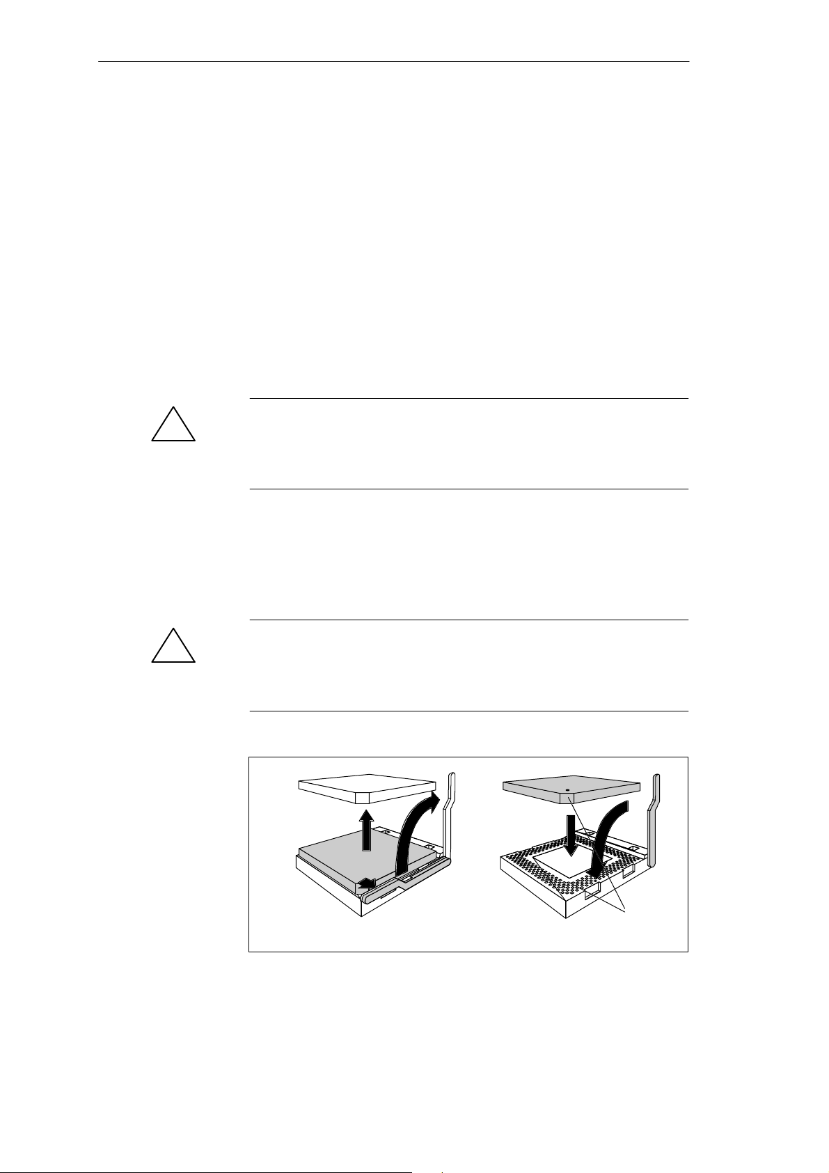
1. Plug the card diagonally into the corresponding slot (1). Make sure that
the marked slot and the two holes on the card engage properly with the
centering pivot of the carrying device.
2. Press the card lightly down until it locks into place (2).
2
1
Figure 2-2 Installing the memory card
Removing the
Memory Card
Proceed as follows to remove a memory card:
1. Press the holding clips on the left and right side carefully outwards (1).
2. Tilt the memory card forward (2) and pull it diagonally out of the slot (3).
1
Figure 2-3 Removing the memory card
3
2
1
2-10
SIMA TIC PC RI25/45, Technical Description
C79000-G7076-C808-01
Page 33

2.6 Changing the Backup Battery
Motherboard
Battery Power
Supply for
Real-time Clock
and Configuration
Battery Voltage
Too Low
Changing the
Battery
A backup battery powers the real-time clock even after the PC is switched
off. In addition to the time of day, all information about the SIMATIC PC
(configuration) is stored. If the backup battery fails or is removed, these data
are lost.
Because of the clock’s low power consumption and the lithium battery’s high
capacity, the battery can provide backup power for the real-time clock for
several years. Therefore, changing the battery is only seldom required.
If the battery voltage is too low, the current time setting is lost and a correct
configuration can no longer be guaranteed.
In this case, you must replace the battery. The battery is located underneath
the bus board.
To change the battery, please proceed as follows:
1. Switch off your PC and unplug all connecting cables.
2. Open the unit as described in Section 1.4.
3. Remove the drive support.
4. Now replace the backup battery, which is attached to the motherboard by
a short length of a cable.
!
Resetting SETUP
5. Reassemble the drive support and close the unit.
Caution
You may only replace the lithium battery with an identical battery or a
battery type recommended by the manufacturer.
Dispose of used batteries in keeping with local regulations (special waste). If
returned to the manufacturer, the battery materials can be recycled (Order
No.:W79070-G13212-S2).
After having changed the backup battery, you have to reset the configuration
data of your PC using the SETUP program.
SIMA TIC PC RI25/45, Technical Description
C79000-G7076-C808-01
2-11
Page 34

Motherboard
2.7 Block Diagram of the Motherboard
LT1083CP
5V–> 3.3V
CPU–io VCC
1.2A
Cache
160pol Con.
System controller
PIIX
82371FB
208PQFP
PCMCIA–CTRL
VG–469
VCC/
VPP
DC/DC
HA 3..31,HD 0..63
3.3V/5V
X23
5V
D6
D8
LT1083CP
5V–> 3.3/2.5V
N8
1A1A
CPU–core VCC
Host 64Bit data bus 32 Bit address bus 3.3V
control lines
HA 3..31
3.3V/5V
TSC
82437FX
Memorycontroller
208PQFP
’ABT245
SKAN
SIMATIC S5/S7
VCC/
VPP
D7
PLINK 0..15
DD 0..15
SA 8..19
’ABT245
D10
DC/DC
N7
’ABT245
D14..16
Primary Fast IDE
Secondary Fast
10.5MHz,
21MHz
Optically
isolated
MA0..11
Hard disk
’ABT245
max.5A(core)
max.0.5A(IO)
dRAM 8,16,32,64,128MB
72pin SIMM
RAS 1/2
72pin SIMM
X19
RAS 3/4
72pin SIMM
X21
RAS 1/2
X20
RAS 3/4
X22
3.3/5 V PCI –BUS AD0..32
Hard disk/
CD–ROM
IDE
ISA–BUS 16Bit data 24Bit address 5V
SA0..16
SPC2
’ABT245
D9
FlashBios
128/256 kByte
RS485
Pentium
Socket 7
split 3.3V
72pin SIMM
XD 0..7
D13
MD0..31
5V
32kHz
X12
321 SPGA Ziff
MD0..7,16..23,32..39,48..55
MD32..63
Connector
for Riser–Board
3.6V
50,60,66MHz
Clocksel
HD0.7,16..23,32..39,48..55
TDP
82438FX
MD8..15,24..31,40..47,56..63
188pin.
UltraIO
PC87306
3.3V/5V
MUX
D5
’4066
D3
TDP
82438FX
160QFP
Taktgenerator 3.3V
ICD2254
HD8..15,24..31,40..47,56..63
3.3V/5V
PLINK 8..15PLINK 0..7
Riser–Board
D2
256x16
dRAM
514171
CL–GD7543
D4
25,30,33MHz
75150/154 75150/154
TTL
TTY
COM1
14.3181MHz
FrameBuffer
5V
256x16
dRAM
D11
514171
VMA 0..9
VGA–LCD
PCI Slot
3.3V/5V
D12
ISA Slot
5V
ISA Slot
5V
COM2
Legend:
5V....3.3V
5V
800x600 LCD
TFT/STN
3.3V
RC network
D1
ext.VGA
1024x768x256
RC–net
protection
LPT1
EPP/ECP
PCMCIA
Slot–II
Mem. Card
optional
SIMATIC
S5 Modules
Figure 2-4 Motherboard
2-12
3.5”Floppy
MPI
BIOS
Keyboard/Trackball
PS/2 Mouse
SIMA TIC PC RI25/45, Technical Description
Communication
TTY/AG
C79000-G7076-C808-01
Modem
Printer
Centronics
Page 35

2.8 Hardware Ports
Motherboard
Position of
Connectors and
Switches
The following figure illustrates the connector and switch positions of the
components on the motherboard.
X402 X11 X10 X800 X9 X7
X22
X21
X20
X19
S2
1 2 3 4 5 6
S1
1 2 3 4 5 6
X18
X17
Batt.
X1
X24
X6
X15
X4
X3
Figure 2-5 Motherboard
X34
X801
CPU
X12
X80 X90
X23
SIMA TIC PC RI25/45, Technical Description
C79000-G7076-C808-01
2-13
Page 36

Motherboard
Connectors on the
The following connectors are located on the IPC’s motherboard:
Motherboard
Designation Name Meaning
X1 Slotbus ISA/PCI connector connecting motherboard and bus module
X3 Secondary IDE Secondary IDE port Standard ribbon cable
X4 Primary IDE Primary IDE port Standard ribbon cable
X6 Keyboard port MINI DIN keyboard connector
X7 Mouse port MINI DIN PS/2 mouse connector
X9 LPT Parallel port LPT1/printer port (Centronics, 25-pin )
X10 COM1 Serial port 1 (25-pin)
X11 COM2 Serial port 2 (Standard 9-pin)
X12 CPU Processor with cooling unit (Pentium socket 7)
X15 Display module Port for display module cable
X17 Socket Socket for TTY sender module
X18 Socket Socket for TTY receiver module
X19 RAM bank 1, 2 low Socket for RAM
X20 RAM bank 1, 2 high Socket for RAM
X21 RAM bank 3, 4 low Socket for RAM
X22 RAM bank 3, 4 high Socket for RAM
X23 Second level cache Socket for cache
X24 Battery Connector for lithium battery
X26 Fan Fan port +12V
X30 Fan Fan port +12V
X34 Processor Pentium 133 jumper open
X50 Floppy disk Diskette connector
X80 Power 6-pin power supply connection of the motherboard
X90 Power 6-pin power supply connection of the motherboard
X402 VGA Standard VGA (15-pin)
X800 MPI MPI port
X801 CPU type Coding for CPU types
S1 Switch 1 Display type
S2 Switch 2 CPU clock, FlashEPROM, TTY port
2-14
SIMA TIC PC RI25/45, Technical Description
C79000-G7076-C808-01
Page 37

Motherboard
Description of
The following table describes the ports and switches.
Ports and
Switches
Ports Pin designation Description of ports
Floppy Disk X50 T wo-drive capacity (82078 compatible)
360kB, 720kB, 1.2MB, 1.44MB
3F0h-3F7h, 370h-377h, disconnectable
IRQ 6, edge triggered
34-pin standard connector
IDE hard disks X4, X3 Four-drive capacity
170h-177h, 1F0h-1F7h, disconnectable
IRQ14, IRQ15, edge triggered
2*40-pin standard connector
COM1 X10 3F8h-3FFh, disconnectable
IRQ4, edge triggered
25-pin socket connector, V24/V28
COM2 X11 2F8h-2FFh, disconnectable
IRQ3, edge triggered
9-pin, standard connector
LPT1/PRINTER X9 378h-37Fh, disconnectable
IRQ7, edge triggered
25p-pin standard socket connector
VGA X402 3B0h-3BFh, 3C0h-3CFh, 3D0h-3DFh, disconnectable
IRQ9, edge triggered
15-pin standard connector
Keyboard X6 060h-064h
IRQ1, edge triggered
6-pin mini Din socket
Mouse X7 060h-064h
IRQ12, edge triggered
6-pin mini Din socket
Power supply X80, X90 2 PS/2 connector (P8, P9), 6-pin
MPI/DP X800 0CC000h-0CC7FFn or 0DC000h-0DC7FFh
IRQ5, edge triggered
9-pin sub-D socket connector
Special connector Pin designation Description of ports
X15 Reset key, speaker , status bar indicators, power supply , front
connections
only RI25/45: 10-pin connector
X16 Status bar indicators
only PG 740, 760: socket connector for 8-pin flexible connection
X26, X30 Fan supply, 2 connectors (2-pin)
X19, 20, 21, 22 4 SIMM sockets, 32-bit
X1 EISA socket connector for direct connector (ISA; PCI signals)
X23 Socket for second level cache, 64-bit
X12 ZIF socket, CPU socket 7
X24 Lithium battery port
SIMA TIC PC RI25/45, Technical Description
C79000-G7076-C808-01
2-15
Page 38

Motherboard
Switch Position
S1 display type and bus clock.
x signifies that the switch is not relevant for the function described.
S1 (1) S1 (2) S1 (3) Function
on on on 640x480 SS-STN
off on on 640x480 STN monochrome
on off on 640x480 DS-STN
off off off 640x480 TFT
on on off reserved
off on off 640x480 DS-STN spec.
on off off 800x600 DS-STN
off off off 800x600 TFT (standard setting)
S2 (1) S2 (2) Function
on on active TTY port (standard setting)
off x TTY transmission loop separate from
current source (passive setting)
x off TTYE receiving loop separate from current
source (passive setting)
Not used on the RI25/45.
S2 (3) S2 (4) Function
off on Hardware in normal operation (standard
on x Boot-EPROM disabled (Boot module
x off Disable Boot block; ROM pages are
setting)
necessary)
swapped at 32 KB
The switch positions described are for your information only. These settings
are made by the manufacturer and must not be changed.
2-16
SIMA TIC PC RI25/45, Technical Description
C79000-G7076-C808-01
Page 39

Motherboard
Jumper for
Setting the CPU
Type
S1 Display Type
and Bus Clock
S2 Hardware
Configuration
and CPU Clock
X34 Function
Open T ypes of 100, 120, 133, 233 MHz
Closed Types of 150, 166, 200 MHz
Jumper X801 always open
S1 (4) S1 (5) S1 (6) Function
on x x VGA disabled
off x x Onboard VGA (standard setting)
x on x Clock ratio CPU BUS/-CORE 1/2 or 2/5
x off x Clock ratio CPU BUS/-CORE 2/3 or 1/3
x x on Clock ratio ISA/PCI 1/4
x x off Clock ratio ISA/PCI 1/3
The effect of the switch setting S1 (5) depends on jumper X34.
S2 (5) S2 (6) Function
on off 66MHz CPU bus clock (standard setting)
off on 60MHz CPU bus clock
on on 50MHz CPU bus clock
off off Reserved (test mode setting)
SIMA TIC PC RI25/45, Technical Description
C79000-G7076-C808-01
2-17
Page 40

Motherboard
12
3
1234
Figure 2-6 Standard settings for switches S1 (1..6) and S2 (1..6) for
233 MHz Pentium CPU
45
6
6
5
ON
S2
OFF
ON
S1
OFF
Clock Setting
Jumper X34 open closed
S2(5) S2(6) S1(5) S1(6) ISA bus
clock
on off on on 8.25MHz 33MHz 66MHz 133MHz 166MHz
off on on on 7.50MHz 30MHz 60MHz 120MHz 150MHz
on on on off 8.33MHz 25MHz 50MHz 100MHz ––––––
on off off on 8.25MHz 33MHz 66MHz 100/233MHz 200MHz
off on off on 7.50MHz 30MHz 60MHz 90MHz 180MHz
on on off off 8.33MHz 25MHz 50MHz 75MHz 150MHz
PCI bus
clock
CPU bus
clock
CPU core clock
(CPU internal)
Preferable settings are printed in bold letters
Caution
!
Operating a processor at a higher frequency than the maximum permissible
frequency may result in destruction of the processor, data loss, or data
corruption.
2-18
SIMA TIC PC RI25/45, Technical Description
C79000-G7076-C808-01
Page 41

Motherboard
COM1 Port
The port is designed for RS 232. New transfer modes are used, for example,
for converting a parallel port to an SCSI or to an IDE port. Each mode has an
individual pinout.
Pin
No.
1 Shield
2 Transfer data (TxD/D1) Output
3 Receive data (RxD/D2) Input
4 Request to send (RTS/S2) Output
5 Clear to send (CTS/M2) Input
6 Data set ready (DSR/M1) Input
7 Functional ground (GND/E2)
8 Data carrier detect (DCD/M5) Input
9 +TTY Receive data (RxD) Input
10 –TTY Receive data (RxD) Input
11 unassigned
12 unassigned
13 unassigned
14 unassigned
15 unassigned
16 unassigned
17 unassigned
18 +TTY Transfer data (TxD) Output
19 Current source, isolated
20 Data terminal ready (DTR/S1) Output
21 –TTY Transfer data (TxD) Output
22 Incoming call (RI/M3) Input
23 unassigned
24 unassigned
25 unassigned
Description Input/Output
Pin numbers 9, 10, 18, 19, and 21 are unassigned for the different versions of
the motherboard for the SIMATIC PC RI25/45 and must not be used for any
other purpose.
SIMA TIC PC RI25/45, Technical Description
C79000-G7076-C808-01
2-19
Page 42

Motherboard
COM2 Port
Figure 2-7 COM 2 serial interface
Signal Names
Pin
1 DCD Data Carrier Detect
2 RxD Receive Data
3 TxD Transfer Data
4 DTR Data T erminal Ready
5 Signal Ground
6 DSR Data Set Ready
7 RTS Request to Send
8 CTS Clear to Send
9 Ri Ring Indicator
Abbreviations Signal Designation
2-20
SIMA TIC PC RI25/45, Technical Description
C79000-G7076-C808-01
Page 43

Motherboard
LPT1 Printer Port
The parallel port offers three transmission modes: SPP, EPP, and ECP. The
SPP mode (Standard Parallel Port mode) is the standard mode which is
usually used to trigger or address a printer. Both EPP (Enhanced Parallel
Port) and ECP (Extended Capabilities Port) are transmission modes which
permit data transfer rates of 2 up to 2.4 Mbytes/s. Such rates require I/O
devices which support these new modes.
Both modes are used, for example, for converting a parallel port to an SCSI
or to an IDE port. Each mode has an individual pinout.
1
14
25
13
Signal
Description
SPP Mode
Figure 2-8 LPT1 parallel port
Pin No.
1 /Strobe Output (open collector)
2 Data - Bit 0 Output (TTL level)
3 Data - Bit 1 Output (TTL level)
4 Data - Bit 2 Output (TTL level)
5 Data - Bit 3 Output (TTL level)
6 Data - Bit 4 Output (TTL level)
7 Data - Bit 5 Output (TTL level)
8 Data - Bit 6 Output (TTL level)
9 Data - Bit 7 Output (TTL level)
10 /ACK (Acknowledge) Input (4.7 kW pull up)
11 BUSY Input (4.7 kW pull up)
12 P.E. Input (4.7 kW pull up)
13 SELECT Input (4.7 kW pull up)
14 /AUTO FD Output (open collector)
15 /ERROR Input (4.7 kW pull up)
16 /INIT Output (open collector)
17 SELECT IN Output (open collector)
18
:
25
GND –
Description Input/Output
SIMA TIC PC RI25/45, Technical Description
C79000-G7076-C808-01
2-21
Page 44

Motherboard
VGA
Pinout
The VGA socket connector has the following pinout:
6
11
10
15
Figure 2-9 VGA socket connector
Pin
Description Pin Description
1
5
1 Video signal red 9 Code (no pin)
2 Video signal green 10 Ground synchronization
3 Video signal blue 11 Display ID bit 0
4 Display ID Bit 2 12 Display ID bit 1
5 Ground 13 Horizontal synch.
6 Ground red 14 Vertical synch.
7 Ground green 15 Display ID bit 3
8 Ground blue
2-22
SIMA TIC PC RI25/45, Technical Description
C79000-G7076-C808-01
Page 45

Motherboard
Connecting an
External Keyboard
Pinout
You can connect an external keyboard to your IPC. The connector has the
following pinout:
6
4
View of socket connector
Figure 2-10 Connecting cable for external keyboard
Pin
5
3
12
Description
1 Keyboard data line
2 Open (mouse data line)
3 0 V
4 +5 V
5 Keyboard clock
6 Keyboard ON/OFF (mouse clock)
SIMA TIC PC RI25/45, Technical Description
C79000-G7076-C808-01
2-23
Page 46

Motherboard
Connecting the
PS/2 Mouse
Pinout
You can connect an external PS/2 mouse to your IPC. The connector has the
following pinout:
6
4
View of the socket conenctor
Figure 2-11 Connecting the PS/2 mouse
Pin
Description
5
3
12
1 Mouse data line
2 Open
3 0 V
4 +5 V
5 Mouse clock
6 Open
2-24
SIMA TIC PC RI25/45, Technical Description
C79000-G7076-C808-01
Page 47

Motherboard
MPI/DP Port
Pinout
The MPI/DP socket connector has the following pinout:
1
6
9
5
Figure 2-12 MPI/DP socket connector
Pin No.
Abbreviation Description Input/
1 NC Pin 1 is unassigned –
2 NC Pin 2 is unassigned –
Output
3 LTG_B Data line B Input/
Output
4 RTSAS RTSAS control signal for receive
Input
data current. Signal ’1’ is active
when the directly linked
programmable controller transmits
data.
5 M5EXT M5EXT Ground (GND) of 5 V
Output
supply. The current load of an
external consumer connected
between P5EXT and M5EXT must
not exceed a maximum of 90 mA.
6 P5 EXT P5EXT supply (+5 V) of 5V
supply. The current load of an
external consumer connected
between P5EXT and M5EXT must
not exceed a maximum of 90 mA.
7 NC Pin 7 is unassigned –
8 LTG_A Data line A Input/
Output
9 RTS_PG RTS output signal. The signal is ’1’
Output
when your IPC starts transmitting.
Shield On connector shell
SIMA TIC PC RI25/45, Technical Description
C79000-G7076-C808-01
2-25
Page 48

Motherboard
2.9 Hardware Addresses
How Memory
Decoding Works
The memory address area of a Pentium CPU has a capacity of 4 Gbyte.
Together with the 64-bit-wide CPU data bus, the CPU is equipped with
29 address lines (A3...A31) and 8 bus enable lines (BE0...BE7) which encode
the non-existent byte address lines A0, A1 and A2. The CPU address bus is
mapped via system controller (TSC) on the PCI address bus. Memory
addresses from 0000 0000h to 0009 FFFFh (640 Kbytes) and from 0010
0000h to 07FF FFFFh (127 Mbytes) are not included.
The ISA bridge maps the ISA address bus exactly once on the PCI address
bus via the PIIX (PCI ISA IDE accelerator) block. The ISA address bus for 8
bit modules covers the address area from A0 to A19 which corresponds to the
CPU addresses from 0000 0000h to 000F FFFh (1 Mbyte). The address bus is
extended with the address lines A20...A23 for 16-bit ISA modules and
therefore addresses from 0000 0000h to 00FF FFFFh (16 Mbytes).
Special memory read/write signals which are only activated in case of a logic
zero level of the address lines A20, A21, A22 and A23 make the distinction
between the 1 Mbyte and the 16 Mbyte ISA address areas.
If the CPU references address areas which are occupied by the main memory,
ISA bus control signals do not occur; that is, ISA bus modules within this
memory area are not referenced. In the reverse case, an ISA bus master
cannot reach addresses higher than 16 Mbytes. In order to gain a larger
address area than the memory address area with a maximum range of
640kByte to 1 Mbyte, different decoding holes in the Pentium programming
device motherboard are provided for dual port RAM extensions:
The CPU address area FFF8 0000h to FFFD FFFFh (512 k-128 k BIOS =
384 Kbyte) is mapped in the ISA address area 00F8 0000h to
00FD FFFFh and is always referenced in the CPU address area. Decoding
the address lines A24 to A 31 which do not exist on the ISA bus is
fulfilled by special hardware located on the motherboard.
1 Mbyte of memory address area can be assigned to the ISA bus in the 16th
Mbyte. This option can be activated/deactivated in the SETUP procedure.
During the division of the address areas, a distinction is made between the:
Memory address area and
I/O address area
Different read/write signals (I/O, WR, I/O RD, MEMR, MEMW) are used to
reference these areas. The following tables will give you the descriptions of
the individual functional groups for more details.
2-26
SIMA TIC PC RI25/45, Technical Description
C79000-G7076-C808-01
Page 49

Motherboard
I/O Address
The following table shows the I/O address assignments.
Assignments
Address Size Description
from to byte Basic function Additional functions
0000 000F 16 PiiX DMA 1
0020 0021 2 PiiX PIC 1 Interrupt controller
002E 002F 2 Configuration port Ultra I/O
0040 0043 4 PiiX timer1 (software clock/refresh/speaker)
0060 0060 1 Keyboard controller date
0061 0061 1 PiiX NMI, speaker control
0063 0063 1 PG configuration port write only
0064 0064 1 Keyboard controller CMD/STATUS
0070 0070 1 PiiX NMI enable, RTC Index
0071 0071 1 RTC date
0080 008F 16 PiiX DMA Page Register
00A0 00A1 2 PiiX PIC2 Interrupt controller
00B2 00B3 2 PiiX Power management control, status
00C0 00DE 31 PiiX DMA 2
00F0 00F0 1 Reset numeric error
0100 010F 16 Industrial Ethernet expansion card usually free
0170 0177 8 Secondary IDE channel
01F0 01F7 8 Primary IDE channel
0200 020F 16 Game I/O expansion card usually free
0278 027B 4 LPT 2 unassigned
02F0 02F7 8 GBIP adapter expansion card usually free
02F8 02FF 8 COM2
0300 031F 32 Programming facility
can be switched off in Setup then free
0320 033F 32 unassigned (XT hard disk), SCSI adapter
(AHA1540B)
0340 035F 8 HighGraph (CPU) host interface expansion
card
usually free
SIMA TIC PC RI25/45, Technical Description
C79000-G7076-C808-01
2-27
Page 50

Motherboard
Address Size Description
from to byte Basic function Additional functions
0360 036F 16 PC-Net expansion card usually free
0370 037F 16 Secondary Floppy unassigned
0376 0376 1 Secondary IDE command
0377 0377 1 Secondary IDE status
0378 037F 8 LPT 1
0380 038F 16 SDLC 2 expansion card usually free
03A0 03AF 16 SDLC 1 expansion card usually free
03B0 03BB 12 Monochrome monitor card / VGA
03BC 03BF 4 LPT x unassigned unassigned
03C0 03CF 16 VGA control register
03D0 03DF 16 CGA / VGA control register
03E0 03E1 2 PCMCIA controller
can be switched off in Setup then free
03E8 03EF 2 COM 3 unassigned
03F0 03F5 6 Primary Floppy on board
03F6 03F6 1 Primary IDE command
03F7 03F7 1 Primary IDE status / Floppy Chg.
03F8 03FF 8 COM 1/TTY
0400+ 0400+ LPT 8 ECP LPT
04D0 04D1 8 PiiX PIC 1, 2 Interrupt controller edge/level
control
0CF8 0CFB 4 PCI config index (TSC) 0CF9h PiiX CPU system reset
0CFC 0CFF 4 PCI config data (TSC)
FCF0 FCF2 2 Bus Master Interface prim. IDE register
Command & Status
FCF4 FCF7 4 Bus Master Interface prim. IDE register
Memory Descriptor T able Base Address
FCF8 FCFA 2 Master Interface sec. IDE register Command
& Status
FCFC FCFF 4 Bus Master Interface sec. IDE register
Memory Descriptor T able Base Address
2-28
SIMA TIC PC RI25/45, Technical Description
C79000-G7076-C808-01
Page 51

Motherboard
Assignment of
The following table shows the assignment of memory addresses.
Memory
Addresses
Address Description
from to Size Basic function Additional functions
0000 0000 0007 FFFF 512k Conventional system memory
0008 0000 0009 FBFF 127k Conventional system memory
extended
0009 FC00 0009 FFFF 1k Conventional system memory
extended BIOS data
000A 0000 000A FFFF 64k VGA graphics refresh memory shared SMM for Power
000B 0000 000B 7FFF 32k Monochrome graphics/text refresh
memory
000B 8000 000B FFFF 32k VGA graphics/text refresh memory shared SMM for Power
000C 0000 000C 7FFF 32k VGA-BIOS expansion
000C 8000 000C BFFF 16k ISA memory usually BIOS
expansion
000C C000 000C C7FF 2k MPI when enabled (standard
setting)
000C C900 000C FFFF 14k ISA memory usually BIOS
expansion
000D 0000 000D FFFF 64k PCMCIA when enabled, usually
BIOS expansion
000E 0000 000E BFFF 48k System BIOS via EMM High Dos Memory
000E C000 000E CFFF 4k System BIOS BootMessageLogo via EMM High Dos Memory
000E D000 000E DFFF 4k System BIOS ECSD
(plug & play configuration area)
000E E000 000E FFFF 8k System BIOS Boot Block via EMM High Dos Memory
000F 0000 000F FFFF 64k System BIOS via EMM High Dos Memory
0010 0000 00EF FFFF 14M Extended system memory
00F0 0000 00FF FFFF 1M Extended system memory via Setup ISA Memory
0100 0000 07FF FFFF 112M Extended system memory
0800 0000 FFF7 FFFF 4G-128M-
512k
FFF8 0000 FFFD FFFF 512k-128k ISA memory , dual port memory
FFFE 0000 FFFF FFFF 128k System BIOS (mirrored from
PCI expansion
application
000E 0000 to 000F FFFF)
via Setup ISA Memory
via Setup ISA Memory
management
shared SMM for Power
management
management
via EMM High Dos Memory
via EMM High Dos Memory
via EMM High Dos Memory
via EMM High Dos Memory
via EMM High Dos Memory
SIMA TIC PC RI25/45, Technical Description
C79000-G7076-C808-01
2-29
Page 52

Motherboard
2.10 Interrupt and DMA Assignments
Interrupt
Assignments
Interrupt Description
NMI Expansion slots signal I/O Channel Check 2
IRQ 0 Internal Timer (System clock)
IRQ 1 Keyboard buffer full
IRQ 2 Cascading of interrupt controller 2
IRQ 3 Serial port 2 (COM 2) can be enabled via Setup
IRQ 4 Serial port 1 (COM 1/TTY) can be enabled via Setup
IRQ 5 MPI port can be enabled via Setup
IRQ 6 Floppy
IRQ 7 Parallel port 1 (Printer port LPT 1/EPP/ECP) can be
enabled via Setup
IRQ 8 Battery-backed real-time clock
IRQ 9 VGA controller usually unassigned
IRQ 10 unassigned
IRQ 11 unassigned
IRQ 12 PS/2 Mouse/ keyboard trackball can be enabled via
Setup if no need for mouse or trackball function
IRQ 13 Arithmet. coprocessor - error
DMA
Assignments
IRQ 14 Primary IDE interface can be enabled via Setup
IRQ 15 Secondary IDE interface (only necessary for special
configuration versions) can be enabled via Setup
DMA Channel Data transfer Description
0 8 / 16 bit free
1 8 / 16 bit free
2 8 / 16 bit Floppy
3 8 / 16 bit free
4 Cascading of DMA controller
5 16 bit free
6 16 bit free
7 16 bit free
2-30
SIMA TIC PC RI25/45, Technical Description
C79000-G7076-C808-01
Page 53

2.11 Setup
Motherboard
Setup Settings
Press the <F2> key if you want to call the SETUP while booting. The following table lists the settings.
Menu item Standard Optional
Main
System time
System Date
Diskette A 1.44 MB, 31/2 1.2 MB; 720 KB; 360 KB; 2.88 MB
Diskette B Not installed 1.2 MB; 720 KB; 360 KB; 1.44 MB; 2.88 MB
IDE Adapter O Master AUT O User , 1 - 14, RSRV, 16 - 39
IDE Adapter O Slave AUTO User, 1 - 14, RSRV , 16 - 39
IDE Adapter 1 Master AUT O User, 1 - 14, RSRV, 16 - 39
IDE Adapter 1 Slave AUTO User, 1 - 14, RSRV, 16 - 39
Video System EGA/VGA
Memory cache
External cache Enabled Disabled
Cache system BIOS area Enabled Disabled
Cache video BIOS area Enabled Disabled
Memory shadow
System shadow Enabled
Video shadow Enabled Disabled
Boot sequence
Boot sequence A: then C: C: only, C: then A:
SETUP prompt Enabled Disabled
POST errors Enabled Disabled
Floppy check Enabled Disabled
Summary screen Enabled Disabled
Numlock
Numlock Off ON
Key click Disabled Enabled
Keyboard auto repeat time 30/s 2/s, 6/s, 10/s, 13,3/s, 18.5/s, 21,8/s, 26,7/s, 30/s
Keyboard auto repeat delay 1/2s 1/4s, 3/4s, 1s
RI HW options
Configure MPI address range Addr . CC00 Addr. DC00, Disabled
Internal COM1 3F8, IRQ 4 Disabled
Internal COM2 2F8, IRQ 8 Disabled
Internal LPT1 378, IRQ 7 Disabled
LPT mode Output only Bi-directional, EPP , ECP
Screen resolution
CTR 640 x 480 75 72, 60
SIMA TIC PC RI25/45, Technical Description
C79000-G7076-C808-01
2-31
Page 54

Motherboard
Menu item OptionalStandard
CTR 800 x 600 75 72, 60, 50
CTR 1024 x 768 72 Interlaced, 60, 72
Trackball / PS/2 mouse External Internal, Disabled
Advanced
PCI devices
PCI device, Slot#1
Enable master Enabled Disabled
Default latency timer Yes No
Latency timer 0040 0 - 280H in steps of 8
PCI device, Slot#2
Enable master Enabled Disabled
Default latency timer Yes No
Latency timer 0040 0 - 280H in steps of 8
PCI IRQ line 1 Auto Select 3, 4, 5, 9, 10, 11, 12, 14, 15, Disabled
PCI IRQ line 2 Auto Select 3, 4, 5, 9, 10, 11, 12, 14, 15, Disabled
PCI IRQ line 3 Auto Select 3, 4, 5, 9, 10, 11, 12, 14, 15, Disabled
PCI IRQ line 4 Auto Select 3, 4, 5, 9, 10, 11, 12, 14, 15, Disabled
Plug & Play O/S No Yes
Reset configuration data No Yes
Diskette controller Enabled Disabled
Local bus IDE adapter Primary & Secondary Disabled, Primary
Large disk access mode DOS Other
VGA interupt Disabled Enabled
Memory gap at 15th Mbyte Disabled Enabled
Security
Supervisor password is Disabled Enabled
User password is Disabled Enabled
Set supervisor password Press Enter Input
Set user password Only after supervisor password
Password on boot Disabled Enabled
Diskette access Supervisor User
Fixed disk boot sector Normal Write-protected
Power
APM Enabled Disabled
Power savings Disabled Customize, Maximum, Medium, Minimum
Power saving with customize
Standby timeout Disabled 2, 15, 30 min, 1, 2, 3, 4h
Suspend timeout Disabled 2, 15, 30 min, 1, 2, 3, 4h
Standby CPU speed Med Low, High, Max
Fixed disk timeout Disabled 1, 2, 3, 4, 5, 10, 16 min
CRT timeout Off in Standby On
Exit
Save changes & exit
Exit without saving values
Get default values
Load previous values
Save changes
2-32
SIMA TIC PC RI25/45, Technical Description
C79000-G7076-C808-01
Page 55

Motherboard
Display After Switching ON
Change to BIOS
Setup
Once your PC has been switched on, the following standard setting appears
on the screen:
PhoenixBIOS Version 4.05
Copyright 1985–1995 Phoenix Technologies Ltd., All Rights
Reserved.
SIEMENS PC RI
CPU = Pentium 100 MHz
0000640 K System RAM Passed
0015360K Extended RAM Passed
System BIOS shadowed
Video BIOS shadowed
UMB upper limit segment address: F2xx
Press <F2> to enter SETUP
If you press <F2> while the BIOS prompt is on the screen, the Setup program
in the ROM BIOS is started. This program helps you to set system
characteristics and the hardware configuration of your PC.
Preset values have already been determined before the PC is delivered. You
can alter these default values in the BIOS Setup. After saving the current
settings and exiting the BIOS Setup, your alterations become valid.
Once you have started up BIOS Setup, the main Setup menu appears on your
screen:
Menu bar
Selectable
menu options
Operating keys
PhoenixBIOS Setup-Copyright 1985-95 Phoenix Technologies Ltd.
Help
Exit
Advanced
Select Item
Select Menu
[ 15:55:32 ]
[ 11/17/1995 ]
640 KB
15 MB
+ / –
Change Values
Enter Select
Sub-MenuF9F10
Main Security Power Exit
System Time:
System Date:
Diskette A: [ 1.44 MB, 31/2” ]
Diskette B: [ Not Installed ]
IDE Adapter 0 Master (C: 3249 MB)
IDE Adapter 0 Slave (None)
IDE Adapter 1 Master (None)
IDE Adapter 1 Slave (None)
Video System: EGA/VGA
Memory Cache:
Memory Shadow:
Boot Sequence: [ A: then C: ]
Numlock: [ Off ]
RI Hardware Options
System Memory:
Extended Memory:
F1
ESC
Figure 2-13 SETUP: Main Menu (example RI 45)
Item Specific Help
,
Shift-Tab Enter, or
Tab
selects field.
Help window
Setup Defaults
Previous Values
SIMA TIC PC RI25/45, Technical Description
C79000-G7076-C808-01
2-33
Page 56

Motherboard
Menu Structure
The screen form is divided into four parts. In the upper part, you can select
the menu titles [Main] [Advanced] [Security] [Power] [Exit]. In the middle
part, on the left side, you can select different settings or submenus. The right
side offers short help texts referring to the currently selected menu command.
The lower part indicates operating keys.
You can jump from one menu to another using the left or right arrow keys:
[←] or [→].
Menu Description
Main Set system characteristics
Advanced Define expanded system configuration
Security Define access rights; for example, password
Power Define power management functions
Exit Save settings and exit SETUP
2-34
SIMA TIC PC RI25/45, Technical Description
C79000-G7076-C808-01
Page 57

2.11.1 Main Menu
Motherboard
Overview
Selectable
menu options
The main menu has the following structure:
PhoenixBIOS Setup-Copyright 1985-95 Phoenix Technologies Ltd.
Main Security Power Exit
System Time:
System Date:
Diskette A: [ 1.44 MB, 31/2” ]
Diskette B: [ Not Installed ]
IDE Adapter 0 Master (C: 3249 MB)
IDE Adapter 0 Slave (None)
IDE Adapter 1 Master (None)
IDE Adapter 1 Slave (None)
Video System: EGA/VGA
Memory Cache:
Memory Shadow:
Boot Sequence: [ A: then C: ]
Numlock: [ Off ]
RI Hardware Options
System Memory:
Extended Memory:
F1
ESC
Figure 2-14 Main SETUP menu (RI45 example)
Help
Exit
Advanced
Select Item
Select Menu
[ 15:55:32 ]
[ 11/17/1995 ]
640 KB
15 MB
+ / –
Change Values
Enter Select
Item Specific Help
,
Tab
Shift-Tab Enter, or
selects field.
Sub-MenuF9F10
Setup Defaults
Previous Values
Settings in the
Main Menu
Use the arrow keys [↑] and [↓] to select one of the following menu options in
the main menu:
Menu option Description
System Time Sets or displays the current time
System Date Sets or displays the current date
Diskette A Sets type of installed floppy disk drive
Diskette B Sets type of installed floppy disk drive
Video system Displays video system setting
Submenus
IDE Adapter Sets type of installed hard disk drive
Video Displays monitor settings
Memory cache/shadow Sets memory options
Boot sequence/numlock Sets boot options
RI hardware options Sets RI special characteristics
SIMA TIC PC RI25/45, Technical Description
C79000-G7076-C808-01
2-35
Page 58

Motherboard
System Time and
System Date
Diskette A/
Diskette B
System Time and System Date show the current time and date. After having
selected the corresponding menu option you can set the system time with the
[+] and [–] keys starting with
hour, then minutes, then seconds and the system date in the order
month, day, year.
Use the tabulator key to jump from one setting to another (for example, from
hours to minutes, etc.) within the menu option Time or Date.
This menu option helps you to set the installed type of floppy disk drive. The
following settings are possible:
[not installed] If no disk drive has been installed. (Standard
setting floppy disk drive B)
[360 KB, 5 1/4”]
[1.2 MB, 5 1/4”]
[720 KB, 3 1/2”]
[1.44 MB, 3 1/2”] Standard setting for installed floppy disk drive A
[2.88 MB, 3 1/2”]
2-36
SIMA TIC PC RI25/45, Technical Description
C79000-G7076-C808-01
Page 59

Motherboard
Hard Disk Drive
IDE Adapter
After selecting one of these menu options, the following submenu appears:
PhoenixBIOS Setup-Copyright 1985-95 Phoenix Technologies Ltd.
Main Security Power ExitAdvanced
IDE Adapter 0 Master (C: 853 Mb)
Autotype Fixed Disk
Type:
Cylinders:
Heads:
Sectors/Track:
Write Precomp:
Multi-Sector Transfers:
LBA Mode Control:
32 Bit I/O:
Transfer Mode:
F1
Help
ESC
Exit
Select Item
Select Menu
[Press Enter]
[User]
3249 MB
[ 6296]
[ 16]
[ 63]
[None]
[16 Sectors]
[Enabled]
[Enabled]
[Fast PIO 3]
+ / –
Change Values F9
Enter Select
Figure 2-15 Submenu “Hard Disk Drive IDE Adapter” (RI45 example)
Item Specific Help
Attempts to automatically detect
the drive type for drives that
comply with ANSI specifications
Setup Defaults
Sub-Menu
F10
Previous Values
Autotype Hard Disk
The system parameters you can select in this submenu are usually stored on
the corresponding IDE drive and are read out of the IDE drive and entered in
the screen form after you have selected the option Autotype Hard Disk.
CD-ROM drives with IDE interface (ATAPI) are not entered in this
option.
If the option Autotype Hard Disk has been selected for a non-existent hard
disk, the procedure is canceled after max. 5 minutes because of timeout. The
current settings remain unchanged. It is therefore useful only to execute an
Autotype for existing system hard disks.
In the standard configuration of your PC, only one hard disk drive connected
to IDE adapter 0 is set as master. The setting of the option Type for all other
hard disks is [none].
In some cases it might be necessary to modify the suggested hard disk
parameters. Select the corresponding menu option for this purpose and
choose the desired value using the [+] and [–] keys. Enter [none] as Type if
no IDE hard disk or IDE CD-ROM has been installed. Enter a number from 1
to 39 to use a predefined hard disk type.
For user-defined hard disk types enter “user” and set the parameters for the
options Cylinders, Heads, Sectors/Track, WritePrecomp.
SIMA TIC PC RI25/45, Technical Description
C79000-G7076-C808-01
2-37
Page 60

Motherboard
Multi-Sector
Transfers
LBA Mode Control
32-bit I/O
Transfer Mode
The option Multi-Sector Transfers defines the number of sectors transferred
per interrupt. This value depends on the drive and should only be set using
the Autotype function.
Disabled 1 sector
2, 4, 6, 8, 16 sectors
A hard disk capacity higher than 528 Mbytes is supported with the setting
“enabled” with the menu option LBA Mode control (which can be enabled or
disabled). This value depends on the drive and should only be set using the
Autotype function.
Define the access mode for the drive under menu option 32-bit I/O.
Disabled 16 bit access
Enabled 32 bit access
Set the transfer speed to the IDE drive with the menu option Transfer Mode.
This value depends on the drive and should only be set using the Autotype
function.
We recommend you use the Autotype function. Only use the manual setting
option to set old hard disks without IDE features.
Depending on the operating system used; for example, SCO OOT3.0, SORIX
etc., it may be necessary to disable the “LBA Mode” in some cases. Press
<ESC> to exit the submenu.
2-38
SIMA TIC PC RI25/45, Technical Description
C79000-G7076-C808-01
Page 61

Motherboard
Memory Cache
If you call up the menu option Memory Cache, the following submenu
appears:
PhoenixBIOS Setup-Copyright 1985-95 Phoenix Technologies Ltd.
Main Security Power ExitAdvanced
Memory Cache
Cache:
Cache System BIOS area:
Cache Video BIOS area:
F1
ESC
Help
Exit
Select Item
Select Menu
[Enabled]
[Enabled]
[Enabled]
+ / –
Change Values F9
Enter Select
Item Specific Help
Cache Controls. If Diasabled is
selected, then both internal and
external Cache are disabled. If set
to Enabled, then internal Cache
and optionaly external Cache are
enabled. System and Video BIOS
Cache settings have no effect, if
this item is set to Disabled.
Setup Defaults
Sub-Menu
F10
Previous Values
Figure 2-16 Submenu “Memory Cache”
The cache memory is a fast intermediate memory located between the CPU
and the main memory (dRAM). If the feature has been enabled, repeated
memory access is not performed in the main memory but in the faster cache
memory. Some hardware or software might require you to disable your cache
memory, because the necessary program execution or waiting times become
too short due to the fast cache memory.
SIMA TIC PC RI25/45, Technical Description
C79000-G7076-C808-01
2-39
Page 62

Motherboard
Memory Shadow
When you call up the menu option Memory Shadow in the main menu, the
following submenu appears:
PhoenixBIOS Setup-Copyright 1985-95 Phoenix Technologies Ltd.
Main Security Power ExitAdvanced
Memory Shadow
System shadow:
Video shadow: [Enabled]
F1
ESC
Help
Exit
Select Item
Select Menu
Enabled
+ / –
Enter Select
Change Values F9
Item Specific Help
Video BIOS may be copied to
shadow RAM for increased performance.
Setup Defaults
Sub-Menu
F10
Previous Values
Figure 2-17 Submenu “Memory Shadow”
Some parts of the EPROM; for example, those which contain
PowerOnSelfTests and the BasicInOutputSystem are copied into the dRAM
memory (shadow memory) providing faster access. System shadow is always
enabled because the system BIOS is always copied into the faster RAM.
Video shadow enabled copies the BIOS expansion for display in the RAM
Video shadow disabled does not copy the BIOS expansion for display in the RAM
These settings are only valid if an extended VGA graphics interface is used.
2-40
SIMA TIC PC RI25/45, Technical Description
C79000-G7076-C808-01
Page 63

Motherboard
Boot Sequence
When you call up the menu option Boot Sequence in the main menu, the
following submenu appears:
PhoenixBIOS Setup-Copyright 1985-95 Phoenix Technologies Ltd.
Main Security Power ExitAdvanced
Boot Options
Boot sequence:
Setup prompt: [Enabled]
POST errors: [Enabled]
Floppy check: [Enabled]
Summary screen: [Enabled]
F1
Help
ESC
Exit
[A: then C:]
Select Item
Select Menu
+ / –
Change Values F9
Enter Select
Item Specific Help
Order system searches drives for
a boot disk.
Setup Defaults
Sub-Menu
F10
Previous Values
Figure 2-18 Submenu “Boot Options”
Boot sequence
Sets the boot sequence
A: then C: first boot Floppy A: then Drive C:
C: then A: first boot Drive C: then Floppy A:
C: only only boot Drive C:
SETUP prompt A SETUP prompt appears at the bottom of the screen
during system startup
POST Errors If an error is detected during the system startup period,
startup is canceled
Floppy check The floppy head is moved in a few steppings and then
back again during the startup period. This test is required
to reinitialize the drive.
Summary screen After the startup period the most important system
parameters are displayed on the screen.
The entry “enabled” releases the corresponding feature; “disabled” blocks it.
SIMA TIC PC RI25/45, Technical Description
C79000-G7076-C808-01
2-41
Page 64

Motherboard
Numlock
When you call up the menu option Numlock in the main menu, the following
submenu appears:
PhoenixBIOS Setup-Copyright 1985-95 Phoenix Technologies Ltd.
Main Security Power ExitAdvanced
Keyboard Features
Numlock:
Key Click: [Disabled]
Keyboard auto-repeat rate: [30/sec]
Keyboard auto-repeat delay: [1/2 sec]
F1
ESC
Help
Exit
Select Item
Select Menu
[Off]
+ / –
Enter Select
Change Values F9
Item Specific Help
Selects Power-on state for Numlock
Setup Defaults
Sub-Menu
F10
Previous Values
Figure 2-19 Submenu “Keyboard Features”
Numlock
Numlock is switched on/off after PowerOn
Key Click Pressing a key can be perceived by a “click”
Keyboard auto-repeat rate Increase of the automatic-repeat rate of the
keyboard
Keyboard auto-repeat delay On-delay of the automatic-repeat feature
2-42
SIMA TIC PC RI25/45, Technical Description
C79000-G7076-C808-01
Page 65

Motherboard
Hardware Options
When you call up the menu option Hardware Options in the main menu, the
following submenu appears:
PhoenixBIOS Setup-Copyright 1985-95 Phoenix Technologies Ltd.
Main Security Power ExitAdvanced
PC RI Hardware Options
Configure MPI Addr. Range:
Internal COM1:
Internal COM2: [2F8, IRQ 3]
Internal LPT1:
LPT Mode: [Output Only]
Screen Resolution
CRT 640 x 480: [75 Hz]
CRT 800 x 600:
CRT 1024 x 768: [75 Hz]
Trackball / PS/2 Mouse: [External]
F1
ESC
Help
Exit
Select Item
Select Menu
[Addr. – CC00H]
[3F8, IRQ 4]
[378, IRQ 7]
[75 Hz]
+ / –
Change Values F9
Enter Select
Figure 2-20 Submenu “PC RI Hardware Options”
Item Specific Help
Configures the address range or
disables MPI. To prevent address
conflicts, choose between two
different base addresses.
Setup Defaults
Sub-Menu
F10
Previous Values
In this submenu, you assign parameters to the ports located on the
motherboard.
Configure MPI Addr . Range Address area of the MPI which is referenced.
Internal COM1 Enables the COM1/TTY port
Internal COM2 Enables or disables the COM2 port
Internal LPT1 Enables or disables the printer port
LPT Mode If LPT1 port has been enabled you can set the
Screen Resolution
CRT 640 x 480 Refresh rate with a resolution of 640 x 480 pixels
CRT 800 x 600 Refresh rate with a resolution of 800 x 600 pixels
CRT 1024 x 768 Refresh rate with a resolution of 1024 x 768 pixels
Trackball / PS/2 Mouse Internal PS/2 port is enabled, IRQ 12
“0CC00H” “0DC00H” are memory addresses.
MPI covers an address area of 2 Kbytes.
“Disabled” releases the address area.
operating mode using this option
Output Only standard operating
bi-directional printer port can also be used as
input port or EPP support
EPP EPP mode
ECP ECP mode
is occupied
Disabled PS/2 port is disabled, IRQ 12
is available
External PS/2 port is enabled, IRQ 12 is
occupied. The keyboard
trackball is blocked
SIMA TIC PC RI25/45, Technical Description
C79000-G7076-C808-01
2-43
Page 66

Motherboard
2.11.2 Advanced Menu
Menu Structure
Settings
PhoenixBIOS Setup-Copyright 1985-95 Phoenix Technologies Ltd.
Main Security Power ExitAdvanced
Warning!
Setting items on this menu to incorrect values
may cause your system to malfunction.
PCI Devices
Plug & Play O/S [No]
Reset Configuration Data [No]
Diskette controller: [Enabled]
Local Bus IDE adapter:
Large Disk Acces Mode: [DOS]
VGA Interrupt: [Enabled]
Memory Gap at 15 Mbyte:
F1
ESC
Help
Exit
Select Item
Select Menu
[Primary & Secondary]
[Disabled]
+ / –
Enter Select
Change Values F9
Item Specific Help
Sub-Menu
Setup Defaults
F10
Previous Values
Figure 2-21 Menu “Advanced”
Plug & Play O/S
Plug & Play signifies that built-in modules are
automatically recognized and installed if they
support Plug & Play features.
[No] BIOS provides all Plug & Play features
[Yes] The operating system provides a part of
the Plug & Play features
Reset Configuration Data [Yes] Signifies that any previous installation of
Plug & Play is canceled. The
configuration is reinitiated after the next
system startup. The entry is then reset to
[No]. System components that do not
support Plug & Play have to be defined
manually .
[No] After the next system startup system
components with Plug & Play features
are initialized.
Diskette controller Enables or disables the Floppy controller of the
motherboard
Local Bus IDE adapter [Primary] One IDE interface for
a max. of two drives
[Primary and Secondary] Two IDE interfaces for
a max. of 4 drives
[Disabled] no local IDE interface
Large Disk Access Mode [DOS] The drive tables are configured
according to enhanced IDE
compatible DOS drive access
[OTHER] The tables are not adapted
2-44
SIMA TIC PC RI25/45, Technical Description
C79000-G7076-C808-01
Page 67

Motherboard
PCI Devices
VGA Interrupt [Enabled] IRQ 9 is reserved for the VGA card
[Disabled] IRQ 9 is reserved for other devices
Memory Gap at 15 Mbytes [Disabled] The onboard RAM is fully
available.
[Enabled] A 1 Mbyte area of the main
memory address area (from 15
Mbyte, address F0 0000 – FF
FFFF) can be assigned to ISA
expansion modules.
When you call up the menu option PCI Devices in the Advanced menu, the
following submenu appears:
PhoenixBIOS Setup-Copyright 1985-95 Phoenix Technologies Ltd.
Main Security Power ExitAdvanced
PCI Devices
PCI Device, Slot #1:
Enable Master: [Enabled]
Default Latency Timer: [Yes]
Latency Timer: [0040]
PCI Device, Slot #2:
Enable Master: [Enabled]
Default Latency Timer: [Yes]
Latency Timer: [0040]
Item Specific Help
Enable selected device as
a PCI bus master.
Settings
PCI IRQ line 1: [AutoSelect]
PCI IRQ line 2: [AutoSelect]
PCI IRQ line 3: [AutoSelect]
PCI IRQ line 4: [AutoSelect]
F1
ESC
Help
Exit
Select Item
Select Menu
+ / –
Change Values F9
Enter Select
Sub-Menu
Setup Defaults
F10
Previous Values
Figure 2-22 Submenu “PCI Devices”
PCI Device, Slot#1/Slot#2
Enable Master: [Enable] PCI master mode is not permissible for this slot.
[Disable] Master mode is not permissible for this slot.
Default Latency
Timer
[Y es] PCI master module determines the number of active
PCI clock cycles.
[No] The preset latency timer value defines the number of
active PCI clock cycles.
Latency Timer [0040] Number of active PCI clock cycles.
PCI IRQ Line
1, 2, 3, 4
[AutoSelect] Plug & Play defines the interrupt used.
[3, 4, 5, 9, 10, 11] The respective PCI interrupt line is
permanently assigned to the ISA interrupt
[3, 4, 5, 9, 10, 11, 12, 14, 15]
[12, 14, 15]
[Disabled] Interrupts [5, 9, 10, 11, 12, 15] are available to
the ISA bus.
SIMA TIC PC RI25/45, Technical Description
C79000-G7076-C808-01
2-45
Page 68

Motherboard
2.11.3 Security Menu
Overview
Only system parameters in brackets can be edited. In order to prevent
unauthorized use of your PC, you can define two passwords. The supervisor’s
password prevents the use of the floppy disk drive by any other user.
PhoenixBIOS Setup-Copyright 1992-93 Phoenix Technologies Ltd.
Main Security Power ExitAdvanced
Item Specific Help
Supervisor Password is Disabled
User Password is Disabled
Set Supervisor Password
Set User Password Press Enter
Password on boot:
Diskette access:
Fixed disk boot sector:
F1
ESC
Help
Exit
Select Item
Select Menu
Press Enter
Disabled
Supervisor
Normal
+ / –
Change Values F9
Enter Select
Sub-Menu
Setup Defaults
F10
Previous Values
Figure 2-23 Submenu “Security”
2-46
SIMA TIC PC RI25/45, Technical Description
C79000-G7076-C808-01
Page 69

2.11.4 Power Menu
Motherboard
Overview
This menu has the following structure:
PhoenixBIOS Setup-Copyright 1992-93 Phoenix Technologies Ltd.
Advanced
Main
APM: Enabled
Power Savings: Disabled
Standby Timeout: Disabled
Suspend Timeout: Disabled
Standby CPU Speed: MAX
Fixed Disk Timeout: Disabled
CRT Standby-Mode: OFF in Standby
F1
Help
ESC
Exit
Figure 2-24 Submenu “Power”
Security Power Exit
Select Item
Select Menu
+ / –
Enter Select
Change Values F9
Item Specific Help
APM (Advanced Power Management)
allows APM aware software to better
manage power savings.
Setup Defaults
Sub-Menu
F10
Previous Values
The power management menu of your “green PC” offers you a range of
power-saving modes:
APM [Enabled] The operating system can be switched off
any superfluous system resource.
[Disabled] Disables the APM (Advanced Power
Management) access of the operating system.
Power Savings [Disabled] No power-saving parameter settings
[Maximum] [Medium] [Minimum] [Customize]
Preset power-saving parameters for
maximum, medium and minimum powersaving features. The parameters for Standby
Timeout/Suspend T imeout, Standby CPU
Speed, Fixed Disk Timeout and CR T Mode
are set correspondingly. User-defined
parameters are set with Customize.
SIMA TIC PC RI25/45, Technical Description
C79000-G7076-C808-01
2-47
Page 70

Motherboard
Standby Timeout [disable] No Standby mode
[30min] minutes causing the PC to
enter Standby mode
[1hr] [2hr] [3hr] [4hr] Hours causing the PC to enter
Standby mode during absence
of any mouse or keyboard
operation
Suspend Timeout [disable] No Suspend mode
[30min] minutes causing the PC to
enter Suspend mode
[1hr] [2hr] [3hr] [4hr] Hours causing the PC to enter
Suspend mode during absence
of any mouse or keyboard
operation
When the system goes into suspend mode, the CPU is deactivated and can
only be restarted by an interrupt; for example, keyboard, mouse, COM1/2,
hard disk.
Standby CPU Speed CPU speed in standby mode
[Low] 1/16 CPU Clock
[Medium] 1/8 CPU Clock
[High] 1/4 CPU Clock
[Max] 1/1 CPU Clock
Fixed Disk Timeout [1min] [2min]
[3min] [4min]
[5min] [10min]
[16min]
Minutes causing the hard disk drive to switch off if there
are do disk read/write operations. If any access to the hard
disk is made after is has been switched off access delay
occurs during which the hard disk is re-accelerated.
CRT [OFF in Standby] Signifies that the synchronous signals
to the VGA graphics interface are shut
off in standby mode. The connected
monitor also enters standby mode.
[ON] Monitor or display remains in
operation.
2-48
SIMA TIC PC RI25/45, Technical Description
C79000-G7076-C808-01
Page 71

2.11.5 Exit Menu
Motherboard
Overview
Always exit the setup program via the following submenu.
PhoenixBIOS Setup-Copyright 1992-93 Phoenix Technologies Ltd.
Advanced
Main
Save Changes & Exit
Exit Without Saving Changes
Get Default Values
Load Previous Values
Save Changes
F1
Help
ESC
Exit
Figure 2-25 Submenu “Exit”
Security Power Exit
Select Item
Select Menu
+ / –
Enter Select
Item Specific Help
Exit after writing all changed SETUP
item values to CMOS.
Change Values F9
Sub-Menu
F10
Setup Defaults
Previous Values
Save Changes & Exit
All modifications are saved, and a restart with the
current parameters is performed.
Exit Without Savings Changes All modifications are abandoned and a restart with
the preset parameters is performed.
Get Default V alues All modifications are saved as default settings. The
hard disk has to be set explicitly.
Load Previous Values Previously saved parameters are restored.
Save Changes Intermediate memory of all Setup entries.
SIMA TIC PC RI25/45, Technical Description
C79000-G7076-C808-01
2-49
Page 72

Motherboard
Documenting Your
System
Configuration
System Parameter Standard Settings Y our Entries
Diskette A 3.5 in., 1.44 MB
Diskette B Not installed
Hard Disk 1 Submenu: Autotype Fixed Disk
Hard Disk 2 Not installed
Memory Cache Submenu: Enabled
Memory Shadow Submenu: Enabled
Boot Sequence A: then C:
Numlock On
RI Hardware Options
MPI Address
Internal COM1:
Internal COM2:
Internal LPT1:
LPT Mode:
CRT resolution:
CRT 640 x 480:
CRT 800 x 600:
CRT 1024 x 768:
Internal mouse:
If you have made any modifications to your standard SETUP settings, you
can enter them in the following table. You therefore have easy access to the
values you have set if you have to make any hardware modifications later.
user xxx MB
Cache: Enabled
System: Enabled
Video Enabled:
Submenu
Addr. CC00H
3F8, IRQ4
2F8, IRQ3
378, IRQ7
output only
75 Hz
75 Hz
75 Hz
External
2-50
SIMA TIC PC RI25/45, Technical Description
C79000-G7076-C808-01
Page 73

2.12 Diagnostic Messages (Port 80)
In order of occurence
Any errors are also output as sound sequences until the test for the video
controller (codes 01 to 4A) occurs. The tone generation mode is structured as
follows:
Example:
2E
Motherboard
Division of the byte into 2-bit combinations
Output of this combination as a sound
sequence, that is
0 → one tone
1 → two tones
2 → three tones
2 → four tones
There is a brief pause between tones
Error during the RAM basic test00101110
0232
Display (hex) Meaning Description
02 TP_VERFY_REAL Test whether CPU is in real mode
04 TP_GET_CPU_TYPE Determine the CPU type
06 TP_HW_INIT Initialize the main hardware (DMA, IRQ)
18 TP_TIMER_INIT Initialize the timer
08 TP_CS_INIT Initialize the chip set
0C TP_CACHE_INIT Initialize the cache
16 TP_CHECKSUM EPROM checksum test
28 TP_SIZE_RAM Determine RAM size
3A TP_CACHE_AUTO Determine cache size
2A TP_ZERO_BASE Set 512k base RAM to 0
2C TP_ADDR_TEST Test the base RAM address cables
2E TP_BASERAML Check the 1.64k base RAM
38 TP_SYS_SHADOW BIOS shadow
20 TP_REFRESH Refresh circuit test
09 TP_SET_IN_POST Start Power On self-test
0A TP_CPU_INIT Initialize CPU
0B TP_CPU_CACHE_ON Turn on cache
0F TP_FDISK_INIT Initialize hard disk
14 TP_8742_INIT Initialize 8742 circuit
1A TP_DMA_INIT Initialize DMA circuit
1C TP_RESET_PIC Reset interrupt controller
22 TP_8742_TEST Test circuit 8742
32 TP_COMPUTE_SPEED Determine clock pulse speed
34 TP_CMOS_TEST T est CMOS RAM
Sound sequence
SIMA TIC PC RI25/45, Technical Description
C79000-G7076-C808-01
2-51
Page 74

Motherboard
Display (hex) DescriptionMeaning
C1 TP_740_INIT Initialize PG 7xx I/Os
3C TP_ADV_CS_CONFIG Configure the advanced chip set
42 TP_VECTOR_INIT Initialize interrupt vectors
46 TP_COPYRIGHT T est copyright
47 TP_PCI_OP_INIT Initialize PCI interface
49 TP_PCI_INIT Initialize PCI interface
48 TP_CONFIG Check configuration
4A TP_VIDEO Initialize video interface
4C TP_VID_SHADOW Copy video BIOS into RAM
52 TP_KB_TEST Keyboard available?
54 TP_KEY_CLICK Switch on/off the keyboard click
76 TP_KEYBOARD Check keyboard
58 TP_HOT_INT Test for unexpected interrupts
4B TP_QUIETBOOT_STAR T Switch off any boot messages
4E TP_CR_DISPLA Y Display copyright notice
50 TP_CPU_DISPLA Y Display CPU type
5A TP_DISPLAY_F2 Display the F2 message for “SETUP”
5B TP_CPU_CACHE_OFF Possibly switch off cache (SETUP settings)
5C TP_MEMORY_TEST Test system memory
60 TP_EXT_MEMOR Y T est extended system memory
62 TP_EXT_ADDR Test A20 address line
66 TP_CACHE_ADVNCD Determine and enable cache size
68 TP_CACHE_CONFIG Configure and test cache
6A TP_DISP_CACHE Display cache configuration
6C TP_DISP_SHADOWS Display configuration and size of the shadow RAM
72 TP_TEST_CONFIG Check SETUP irregularities
74 TP_R TC_TEST Test REAL TIME clock
7C TP_HW_INTS Set IRQ vectors
7E TP_COPROC Check whether the CO processor is present or not
94 TP_DISABLE_A20 Disable A20 line
80 TP_IO_BEFORE Disable IO circuit
85 TP_PCI_PCC Determine PCI circuit
82 TP_RS232 Determine serial ports
84 TP_LPT Determinene parallel ports
86 TO_IO_AFTER Re-enable IO circuit
88 TP_BIOS_INIT Initialize BIOS data area
8C TP_FLOPPY Initialize floppy controller
90 TP_FDISK Initialize hard disk controller
8A TP_INIT_EXT_BDA Initialize external BIOS data area
8B TP_MOUSE T est the internal mouse port
98 TP_ROM_SCAN Search for BIOS expansions
69 TP_PM_SETUP Initialize power management
2-52
SIMA TIC PC RI25/45, Technical Description
C79000-G7076-C808-01
Page 75

Display (hex) DescriptionMeaning
9E TP_IRQS Enable the hardware IRQ
A0 TP_TIME_OF_DAY Set clock time and date
A2 TP_KEYLOCK_TEST Preset keylock
A8 TP_ERASE_F2 Delete F2 message
AA TP_SCAN_FOR_F2 Checl whether to activate setup or not
AC TP_SETUP_CHECK Output any F1 / F2 message
AE TP_CLEAR_BOOT Cancel self-test flag
B0 TP_ERROR_CHECK Check for any possible errors
B2 TP_POST DONE End of self-test
B6 TP_PASSWORD Password query (option)
BC TP_PARITY Cancel parity memory bit
BA TP_DMI
BD TP_BOOT_MENU Display boot menu (option)
BE TP_CLEAR_SCREEN Clear the screen
C0 TP_INIT19 Boot via interrupt 19
D2 Unexpected interrupt
Motherboard
SIMA TIC PC RI25/45, Technical Description
C79000-G7076-C808-01
2-53
Page 76

Motherboard
2-54
SIMA TIC PC RI25/45, Technical Description
C79000-G7076-C808-01
Page 77

Bus Board/Operator Panel
3
Chapter
Overview
Section Description Page
3.1 Technical Specifications 3-2
3.2 Installation and Functional Specifications 3-2
3.2.1 Power Supply Connection 3-3
3.2.2 Power-Good-Signal 3-5
3.2.3 Fan Connector P405, P407 3-6
3.2.4 IDSEL Setting for PCI Slots 3-6
3.3 Operator Panel 3-7
3.4 Operator Panel for SafeCard 3-8
SIMA TIC PC RI25/45, Technical Description
C79000-G7076-C808-01
3-1
Page 78

Bus Board
3.1 Technical Specifications
Slots 6 AT slots
2 PCI slots
Ambient temperature during
operation
Dimensions L x W 198 x 173 mm
Module ID on component side BBG-ISA/PCI-01
3.2 Installation and Functional Specifications
The bus board is a passive connecting element between the motherboard and
the expansion board with a sandwich structure. It is mounted on top of the
motherboard by five screws. The connection to the motherboard is
established by a 198-pin connector.
P400A P400B P401
P402A P402B
J302
J303
POWER OUT
PCI-Slot 1
PCI-Slot 2
J401
J300
J400
J301
max. 60 C
(Spare part order
no. C79451-Z1538-K3)
POWER IN
J404
PWRGD
P407
P405
FAN1 FAN2
ISA-Slot 6
ISA-Slot 5
ISA-Slot 4
ISA-Slot 3
ISA-Slot 2
ISA-Slot 1
Figure 3-1 Connector positions on the ISA/PCI bus board
Connecting range All-in-One
BBG-ISA/PCI-01
3-2
SIMA TIC PC RI25/45, Technical Description
C79000-G7076-C808-01
Page 79

3.2.1 Power Supply Connection
Bus Board
Input
The input consists of two 6-pin power supply connectors with standard pinout
and AT power supply coding. An additional Molex 8619 connector supports
the +5 V / GND.
Output
The output consists of two 6-pin power supply connectors with standard
pinout and AT power supply coding to connect a CPU module.
Input and output connectors are individual that is, with the exception of the
Power-Good-Signals all power lines are interconnected.
Plug Connector P402B Power supply input:
456123
Pin Description
1 GND
2 GND
3 – 5V
4 + 5V
5 + 5V
6 + 5V
Plug Connector P400B Output towards CPU board:
456123
Pin Description
1 GND
2 GND
3 – 5V
4 + 5V
5 + 5V
6 + 5V
SIMA TIC PC RI25/45, Technical Description
C79000-G7076-C808-01
3-3
Page 80

Bus Board
Plug Connector P402A Power Supply Input
456123
Pin Description
1 PWRGD-IN
2 + 5V
3 + 12V
4 – 12 V
5 GND
6 GND
Plug Connector P400A Output towards CPU Board
456123
Pin Description
1 PWRGD-OUT
2 + 5V
3 + 12V
4 – 12V
5 GND
6 GND
3-4
SIMA TIC PC RI25/45, Technical Description
C79000-G7076-C808-01
Page 81

3.2.2 Power-Good-Signal
The Power-Good-Signal of the power supply input (PWRGD-IN) can be
switched onto the Power-Good-Signal of the power supply output
(PWRGD-OUT) of the bus board via a 2-pin conenctor (J400, see below). A
supplementary device; for example, a monitoring module can be logged in.
Bus Board
Plug connector: J401
2
1
open
inserted no module connected (standard setting)
Plug connector: J400
2
1
Pin 1: Power-Good from power supply = Pin 1 of PS input (PWRGD-IN)
Pin 2: Power-Good towards CPU = Pin 2 from PS output
(PWRGD OUT)
The Power-Good-Signal is generated on the bus board by the reset generator
if jumper J401 is open.
Plug connector: J404 always remains open.
SIMA TIC PC RI25/45, Technical Description
C79000-G7076-C808-01
3-5
Page 82

Bus Board
3.2.3 Fan Connector P405, P407
The two connectors P405 and P407 provide the connection of two additional
fans directly operating with a non-stabilized + 12 V power supply.
3.2.4 IDSEL Setting for PCI Slots
Two individual address or bus lines of the local PCI bus can be selected via
the plug connectors J300 and J302 to serve as select signals for both PCI
slots.
Plug connector: J300
Settings:
Bridge 1-2: IDSEL PCI slot 1 = AD 28 (standard setting)
Bridge 2-3: IDSEL PCI slot 1 = AD 27
23 1
Plug connector: J301
23 1
Settings:
Bridge 1-2: IDSEL PCI slot 2 = AD 30 (standard setting)
Bridge 2-3: IDSEL PCI slot 2 = AD 29
Warning
!
Do not modify any standard settings.
3-6
SIMA TIC PC RI25/45, Technical Description
C79000-G7076-C808-01
Page 83

3.3 Operator Panel
The operator panel features:
Two LEDs
Reset switch
Speaker
Bus Board
Single LED green, 5 x 2.5 mm rectangular
1-pin push button, connections on P1 connector (operator panel interface).
Miniature speaker designed for mounting on a printed circuit board,
connections on P1 connector (operator panel interface).
Pin Assignment
Operator Panel
Pin
1 Reset
2 Speaker
3 Coding
4 + 5V
5 GND
6 – –
7 – –
8 – –
9 HD-LED+
10 HD-LED–
Assignment
SIMA TIC PC RI25/45, Technical Description
C79000-G7076-C808-01
3-7
Page 84

Bus Board
3.4 Operator Panel for SafeCard
The operator panel is connected to the safecard module via a short 2-row,
40-pin plug connector with mechanical coding.
The operator panel features:
Four LEDs
Twin LED red/green, 5 x 2.5 mm rectangular
Reset switch
1-pin push button, connections on P1 connector (operator panel interface).
Reset lock
1-pin bridge serving to switch off reset push button, mounted on the back
of the board.
Speaker
Miniature speaker designed for mounting on a printed circuit board,
connections on P1 connector (operator panel interface).
Diagnostic display
Two green 7-segment displays with a character size of approximately 7 to
8 mm, connections on P1 connector (operator panel interface).
3-8
SIMA TIC PC RI25/45, Technical Description
C79000-G7076-C808-01
Page 85

Bus Board
Pin Assignment
RI45 Operator
Panel
Pin Assignment Pin Assignment
1 Reset 21 Display 2, segment 5
2 Speaker 22 Display 1, segment 5
3 Coding 23 Display 2, segment 6
4 + 5V 24 Display 1, segment 6
5 GND 25 NC
6 Power LED/green 26 NC
7 NC 27 NC
8 Lock 28 NC
9 HD LED/+ 29 NC
10 HD LED/green 30 LED Temp.
red
11 Display 2, segment 0 31 LED Temp.
green
12 Display 1, segment 0 32 LED Run
red
13 Display 2, segment 1 33 LED Run
green
14 Display 1, segment 1 34 NC
15 Display 2, segment 2 35 LED FDD.
green
16 Display 1, segment 2 36 NC
17 Display 2, segment 3 37 NC
18 Display 1, segment 3 38 NC
19 Display 2, segment 4 39 NC
20 Display 1, segment 4 40 NC
SIMA TIC PC RI25/45, Technical Description
C79000-G7076-C808-01
3-9
Page 86

Bus Board
3-10
SIMA TIC PC RI25/45, Technical Description
C79000-G7076-C808-01
Page 87

Monitoring Module
4
Chapter
Overview
Section Description Page
4.1 Overview 4-2
4.2 Status and Diagnostic Displays 4-5
4.3 Temperature Monitoring / Display and Fan Control 4-6
4.4 Watchdog (WD) 4-7
4.5 Relay Output 4-9
4.6 Battery-Backed RAM (Optional) 4-10
4.7 Software Interfaces 4-1 1
4.8 Hardware Ports 4-14
SIMA TIC PC RI25/45, Technical Description
C79000-G7076-C808-01
4-1
Page 88

Monitoring Module
4.1 Overview
Function
The SafeCard is a short ISA module. It is used as a monitoring module in
SIMATIC PCs. It monitors the ambient conditions and the operating mode of
the PC, it indicates operating modes and fail-state characteristics and controls
the fans.
SafeCards fulfill the following individual functions:
– Display status
– Monitor temperature and indicate excess or insufficient temperature
– Control fans
– Watchdog
– Serve as relay interface
– Battery-back the optional RAM 64kB
SafeCard messages can be transferred to applications by means of the
SafeCard driver. For installing the SafeCard driver under various operating
systems see the ReadMe.TXT file in directory C:\SAFECARD.
4-2
SIMA TIC PC RI25/45, Technical Description
C79000-G7076-C808-01
Page 89

Monitoring Module
Functional Block
Diagram
ISA D-Bus(0:7)
ISA address bus (0:23)
IOW, IOR, AEN
MEMW , MEMR, BALE
IRQ5, 10, 11, 12, 15
RESETDRV
CLK
Figure 4-1 shows the basic block diagram of a SafeCard. The cross-hatched
blocks represent possible components of the individual PCs.
ISA
Interface
IRQ
Logic
Address
decoder
Conf.
register
Watchdog
Driver for
status display
7-Seg/LEDs
Signaling
relay
Temperature
reference
RESET logic
Fan power
supply
PWR_GOOD
generator
Connector X2
towards LEDs
and 7-Seg.
Relay
connector
X13
Temp.
sensor
via x2
Reset push
button via
x2
4 x 2-pin
connector
X6, 7, 8, 9
Connector
X4 towards
motherboard
CS_RAM
LS_BUS(0:6)
LS_BUS(0:16)
LS_BUS(0:7)
Figure 4-1 Functional block diagram of a SafeCard
64 KB
SRAM
opt.
X14
Battery
optional
SIMA TIC PC RI25/45, Technical Description
C79000-G7076-C808-01
4-3
Page 90

Monitoring Module
Connector and
Switch Positions
1
X12
1
X10
X11
1
1
X6
X7
1
1
X8
1
1
Figure 4-2 illustrates the position of connectors and switches on the monitoring module.
1
X2
Cut-out for lithium
battery
300x120mm
X14
1
2
3
X5
X4
X3
1
1
1
X13
Figure 4-2 Position of connectors and switches on the SafeCard
4-4
SIMA TIC PC RI25/45, Technical Description
C79000-G7076-C808-01
Page 91

4.2 Status and Diagnostic Displays
Monitoring Module
Overview
The diagnostic display for SIMATIC PCs is triggered by the SafeCard and
realized in the form of LEDs and a seven-segment display which are visible
on the operator panel mounted on the front of the device (varies according to
PC). Monitoring features are thus controlled and the current status of the PC
is indicated.
The operator panel is a separate component and only connected to the
SafeCard via a cable (see Section on “Operator panel”).
7-segment Display
Diagnostic port 80H- Output via 7-segment display:
Any write access to I/O port 80 is latched and its value indicated on the
two-digit 7-segment display. Every cold restart of the system (switch
ON/OFF) causes a detailed Power On Self-Test (POST). The POST
controlling steps are displayed as so-called POST codes on the 7-segment
display of the PC. The POST code descriptions are listed in Section 2.12,
“Diagnostic Messages” in the description of the motherboard.
LED Indicators
LED OFF GREEN RED
Power System OFF System ON ––
Disk Inactive Active ––
Run Watchdog inactive Watchdog active Watchdog executed
T emp System OFF Normal internal
The LEDs have the following meanings:
Internal temperature beyond acceptance level or cable
temperature
towards temperature sensor unplugged or interrupted.
SIMA TIC PC RI25/45, Technical Description
C79000-G7076-C808-01
4-5
Page 92

Monitoring Module
4.3 Temperature Monitoring / Display and Fan Control
Temperature
Monitoring
The temperature is measured via a sensor (NTC) and its status is indicated
via a green LED for normal temperature and via a red LED for errors. The
following conditions may cause errors:
Overrange of the acceptance limit of excess temperature
Underflow of the acceptance limit of insufficient temperature
Line break or temperature sensor unplugged
The temperature status can be checked at bit 0 of the I/O cell base address +
0Eh.
An error causes one of the following reactions:
Reaction Option
T empLED changes from GREEN to RED always
Canceling of T empBit in I/O cell base address + 0Eh always
Relay output falls in quiet state always
Initiate IRQ can be set
Note
Monitoring Line
Break
The NTC is a separate component and only connected to the monitoring
module via a plug connector. The NTC is equipped with cable and connector
and is part of the list of components. In order to guarantee correct
temperature monitoring, an NTC with a resistance of 10 kOhm is required
(SBS Order No. 57703-M103-G).
The NTC resistance is commuted to a SafeCard connector via twisted pair
cable. The errors “line break” and “connector unplugged” are additionally
monitored by open-circuit monitoring. A line break is signaled by a
temperature error.
4-6
SIMA TIC PC RI25/45, Technical Description
C79000-G7076-C808-01
Page 93

4.4 Watchdog (WD)
Monitoring Module
Function
Watchdog
Reactions
The watchdog monitors the program execution. The watchdog has the task of
informing the user about different reactions to a program crash.
When you switch on your PC, or when you execute a cold restart (hardware
reset) the watchdog remains in its quiet state, that means that it does not
trigger any reaction and the RUN LEDs remain dark. The description of the
I/O cell base address +0Eh triggers the watchdog. This is indicated by the
green RUN LED The watchdog status can be checked in bit 1 of the I/O cell
base address + 0Eh.
If the watchdog is not triggered within a preset time interval, the following
reactions occur:
Reaction Option
RUN LED changes from GREEN to RED always
Canceling WD bit in cell base address + 0Eh always
Relay output falls in quiet state always
Initiating of PC reset to be set
Transmitting IRQ to PC to be set
If an executed watchdog is retriggered, the green LED is illuminated again.
Options are set via the configuration register bits 6 and 7.
Watchdog
Monitoring Times
TWD
Monitoring times are set in four steps in the configuration register.
Time
TWD1 1 s 0 0
TWD2 2 s 0 1
TWD3 8 s 1 0
TWD4 16 s 1 1
Contents of register base address
+0Eh
Bit 3 Bit 4
SIMA TIC PC RI25/45, Technical Description
C79000-G7076-C808-01
4-7
Page 94

Monitoring Module
Note
If you modify the watchdog time after the watchdog has been activated (that
is during watchdog execution), the watchdog is retriggered.
Marginal
Conditions
In order to secure the recognition of a fail-state from an interrupt-evaluating
unit which is connected to the relay interface, the SafeCard guarantees an
error hold time of at least 500 ms. This also applies if the PC is reset, for
example, after the watchdog has been executed.
4-8
SIMA TIC PC RI25/45, Technical Description
C79000-G7076-C808-01
Page 95

4.5 Relay Output
Monitoring Module
Switching ON/OFF
Conditions
State Diagram
An external unit (for example, a call device, a horn or a signal lamp) can be
informed about the PC’s current system status via the relay output.
After switching ON or resetting the PC, the relay output starts operating (no
error occurs); that is, the relay coil is energized and the switch makes contact,
which means it switches to an active working position.
The relay is deactivated if the watchdog has been executed or excess
temperature occured. The coil is then de-energized and the switch breaks
contact (fail-state); that is, it switches to a de-energized position.
The relay output can also be controlled via bit 1 in the I/O cell base address +
0Dh.
Switching the relay from fail-state to error-free status via the software is
impossible if a fail-state occurs (that is temperature error or watchdog
executed).
The following table shows you the operating status occuring and the
corresponding switch position.
State Switch
position
Normal operation W orking
condition
W atchdog executed De-ener gized
position
User cancels bit 1 in register base address + 0Dh De-energized
position
User sets bit 1 in register base address+ 0Eh W orking
condition
Temperature error De-ener gized
position
Power failure De-ener gized
position
In order to secure the recognition of a fail-state via an interrupt-evaluating
unit which is connected to the relay interface, the SafeCard guarantees an
error hold time of at least 500 ms This also applies if the PC is, for example,
reset after the watchdog das been executed.
Technical
The following table lists the technical specifications of the relays:
Specifications of
the Relays
SIMA TIC PC RI25/45, Technical Description
C79000-G7076-C808-01
Switching voltage DC max. 60V
Switching current DC max. 1 A
Switching capacity DC max. 30 W
Limiting continuous current DC max. 1 A
4-9
Page 96

Monitoring Module
4.6 Battery-Backed RAM (optional)
Size
Addressing
Address Settings
Backup
The maximum capacity of the battery-backed RAM is limited to 64 Kbytes
because the PC’s memory area for ADD-ON components is very limited and
the addressing of the RAM should be located in the memory-mapped area.
The address area listed below applies to the programmer. The motherboard
mirrors the address areas FFF8:0000h to FFFF:FFFFh on to the 16th Mbyte
of the AT bus; that is, on the addresses 00F8:0000h to 00FF:FFFFh.
The base address is set via address switch S1 (on = switch closed).
Address switch
S1
on 000D:0000 to 000D:FFFF (standard setting)
off 00FD:0000 to 00FD:FFFF
RAM address ar ea
A lithium battery provides the RAM backup power.
Battery: lithium battery 3.6V type SL-750 manufacturer: Fa. Sonnenschein
Lithium GmbH
4-10
SIMA TIC PC RI25/45, Technical Description
C79000-G7076-C808-01
Page 97

4.7 Software Interfaces
Monitoring Module
Overview
Base Addresses
Reading Register
Base Address
+ 0Eh
RD base address + 0Eh
The module is referenced via an I/O register. Four I/O addresses are occupied
(xxCh, xxDh, xxEh, xxFh). Only the backed-up RAM is located in the
memory-mapped area.
In order to avoid address overlaps, alternative addresses are available. These
are set by two address switches S2 and S3 (on = switch closed).
Address
switch S3
on on 220h
on off 2A0h
off on 320h Standard setting
off off 3A0h
Address
switch S2
Base
addresses
Notes
The monitoring features WD and Temp are provided by the register base
address + 0Eh.
Contents of I/O cell base address + 0Eh on display.
HSB
LSB
TEMP
WD
1 = OK LED green
0 = T emperature error , LED red
1 = WD triggered, LED green
0 = WD not triggered in T
LED=red.
WD
,
If WD is reset or not used (LED OFF) the number 1 is also indicated in this
bit.
SIMA TIC PC RI25/45, Technical Description
C79000-G7076-C808-01
4-11
Page 98

Monitoring Module
Writing the
Register
Base Address
+ 0Dh
WR base address + 0Dh
HSB
Writing the
Register Base
Address + 0Eh
Open-circuit and break-circuit working of the relay output can be defined via
the register base address + 0Dh. This also sets the status of the software LED
or causes a hardware reset of the PC.
LSB
Relay
Reset
SW LED
1 = Break circuit (fail-state)
0 = Open circuit (normal state)
1 = Trigger HW reset
0 = No HW reset
1 = SW LED = red
0 = SW LED = green
The first write access to this register enables the watchdog, WD LED (also
called RUN LED) is set to green.
The watchdog is retriggered by additional write access. At the end of the
watchdog execution time, the watchdog is retriggered by another write
access.
4-12
SIMA TIC PC RI25/45, Technical Description
C79000-G7076-C808-01
Page 99

Monitoring Module
Writing the
Register Base
Address + 0Fh
WR base address + 0Fh
HSB LSB
The register base address + 0Fh defines parameters for interrupts and
watchdog times as well as reactions concerning excess temperature and the
watchdog.
Interrupt selection
0 0 0 No interrupt enabled
0 0 0 IRQ 5
0 1 0 IRQ 15
0 1 1 IRQ 12
1 0 0 IRQ 11
1 0 1 IRQ 10
0 0 TWD = 1 s
0 1 TWD = 2 s
1 0 TWD = 8 s
1 1 T
0 No IRQ with executed
WD 1 IRQ with executed WD
WD
= 16 s
0 Executed WD does not trigger reset
1 Executed WD triggers reset
0 No IRQ with temperature error
1 IRQ with temperature error
Note
If you modify the watchdog time after the watchdog has been activated (that
is during watchdog execution), the watchdog is retriggered.
SIMA TIC PC RI25/45, Technical Description
C79000-G7076-C808-01
4-13
Page 100

Monitoring Module
4.8 Hardware Ports
Signal Output
towards Display
Panel (X2)
Signal
Assignments
Standard design: 2-row, 40-pin plug connector
Pin Signal Type
1 Reset E
2 Speaker A
3 NC (Coding)
4 +5V V
5 GND V
6 Power LED/green A
7 NC
8 Keyboard lock E
9 HD LED/+ (VCC via 330) A
10 HD LED/green (OC) A
11 Display 2 Segment 0 A
12 Display 1 Segment 0 A
13 Display2 Segment 1 A
14 Display1 Segment 1 A
15 Display2 Segment 2 A
16 Display1 Segment 2 A
17 Display2 Segment 3 A
18 Display1 Segment 3 A
19 Display2 Segment 4 A
20 Display1 Segment 4 A
21 Display2 Segment 5 A
22 Display1 Segment 5 A
23 Display2 Segment 6 A
24 Display1 Segment 6 A
25 NC
26 NC
27 NC
28 NC
29 NC
30 LED Temp, red A
31 LED Temp, green A
32 LED Temp, red A
33 LED Run, green A
34 NC
35 LED FDD, green A
36 NC
37 NC
38 NC
39 NC
40 NC
4-14
SIMA TIC PC RI25/45, Technical Description
C79000-G7076-C808-01
 Loading...