

Page 1
Contents
System Unit
1
Motherboard
2
Keyboard Controller
3
Direct Key Module
4
Bus Board
5
Front Adapter Module
6
Monitoring Module
7
Touch Screen
8
Display
9
Hard Disk Drive
10
Floppy Disk Drive
11
CD-ROM Drive
12
Power Supply
13
Connecting Cables
14
Appendix
ESD Guidelines
A
Index
07/99
C79000-G7076-C794
Release 03
PC BI45/FI45 PII
SIMATIC
Technical Description
Page 2

This manual contains notices which you should observe to ensure your own personal safety, as well as
to protect the product and connected equipment. These notices are highlighted in the manual by a
warning triangle and are marked as follows according to the level of danger:
!
Danger
indicates that death, severe personal injury or substantial property damage will result if proper precautions
are not taken.
!
Warning
indicates that death, severe personal injury or substantial property damage can result if proper
precautions are not taken.
!
Caution
indicates that minor personal injury or property damage can result if proper precautions are not taken.
Note
draws your attention to particularly important information on the product, handling the product, or to a
particular part of the documentation.
The device/system may only be set up and operated in conjunction with this manual.
Only qualified personnel should be allowed to install and work on this equipment. Qualified persons
are defined as persons who are authorized to commission, to ground, and to tag circuits, equipment,
and systems in accordance with established safety practices and standards.
Note the following:
!
Warning
This device and its components may only be used for the applications described in the catalog or the
technical description, and only in connection with devices or components from other manufacturers
which have been approved or recommended by Siemens.
This product can only function correctly and safely if it is transported, stored, set up, and installed
correctly , and operated and maintained as recommended.
SIMA TICR, SIMATIC HMI R and SIMATIC NETR are registered trademarks of SIEMENS AG.
Third parties using for their own purposes any other names in this document which refer to
trademarks might infringe upon the rights of the trademark owners.
We have checked the contents of this manual for agreement with the
hardware and software described. Since deviations cannot be precluded
entirely , we cannot guarantee full agreement. However, the data in this
manual are reviewed regularly and any necessary corrections included in
subsequent editions. Suggestions for improvement are welcomed.
Subject to change without prior notice
E Siemens AG 1998
Disclaimer of LiabilityCopyright E Siemens AG 1998 All rights reserved
The reproduction, transmission or use of this document or its contents is
not permitted without express written authority. Of fenders will be liable for
damages. All rights, including rights created by patent grant or registration
of a utility model or design, are reserved.
Siemens AG
Bereich Automatisierungs- und Antriebst echnik
Geschaeftsgebiet Industrie-Automatisierungssysteme
Postfach 4848, D-90327 Nuernberg
Siemens Aktiengesellschaft C79000-G7076-C794
Safety Guidelines
Qualified Personnel
Correct Usage
Trademarks
Page 3

iii
SIMA TIC PC BI45/FI45 PII, Technical Description
C79000-G7076-C794-03
Contents
1 System Unit 1-1. . . . . . . . . . . . . . . . . . . . . . . . . . . . . . . . . . . . . . . . . . . . . . . . . . . . . . . . . . . .
1.1 Technical Specifications 1-2. . . . . . . . . . . . . . . . . . . . . . . . . . . . . . . . . . . . . . . . . .
1.2 Maximum Dimensions of Expansion Modules 1-5. . . . . . . . . . . . . . . . . . . . . . .
1.3 Power Requirements of the Components (Maximum Values) 1-7. . . . . . . . . .
1.4 Removing and Installing Components 1-8. . . . . . . . . . . . . . . . . . . . . . . . . . . . . .
1.4.1 Opening and Closing the System Unit of the BI45 1-10. . . . . . . . . . . . . . . . . . . .
1.4.2 Lowering the FI45 System Box Away from the Front Panel 1-12. . . . . . . . . . . .
1.4.3 Removing the System Box of the FI45 from the Front Panel 1-14. . . . . . . . . . .
1.4.4 Opening and Closing the System Unit of the FI45 1-15. . . . . . . . . . . . . . . . . . . .
1.4.5 Removing and Installing Expansion Modules 1-17. . . . . . . . . . . . . . . . . . . . . . . .
1.4.6 Removing and Installing the Power Supply Unit 1-19. . . . . . . . . . . . . . . . . . . . . .
1.4.7 Removing and Installing the Bus Board 1-21. . . . . . . . . . . . . . . . . . . . . . . . . . . . .
1.4.8 Removing and Installing the Fan 1-21. . . . . . . . . . . . . . . . . . . . . . . . . . . . . . . . . .
1.4.9 Removing and Installing a Floppy Disk Drive or CD-ROM Drive
for the BI45 1-22. . . . . . . . . . . . . . . . . . . . . . . . . . . . . . . . . . . . . . . . . . . . . . . . . . . . .
1.4.10 Removing and Installing a Floppy Disk Drive or CD-ROM Drive
for the FI45 1-24. . . . . . . . . . . . . . . . . . . . . . . . . . . . . . . . . . . . . . . . . . . . . . . . . . . . .
1.4.11 Removing and Installing the Hard Disk of the BI45/FI45 1-26. . . . . . . . . . . . . .
1.4.12 Removing and Installing the Motherboard 1-28. . . . . . . . . . . . . . . . . . . . . . . . . . .
1.4.13 Removing and Installing the Membrane Keyboard or Front Components
of the FI45 1-29. . . . . . . . . . . . . . . . . . . . . . . . . . . . . . . . . . . . . . . . . . . . . . . . . . . . .
1.4.14 Removing and Installing the Keyboard Controller for the FI45 1-30. . . . . . . . .
1.4.15 Removing and Installing the Inverter Module for the FI45 1-30. . . . . . . . . . . . .
1.4.16 Removing and Installing the Display for the FI45 1-31. . . . . . . . . . . . . . . . . . . . .
1.4.17 Removing and Installing the Touch Pad for the FI45 1-31. . . . . . . . . . . . . . . . . .
1.4.18 Removing and Installing the Front Adapter Module for the FI45 1-31. . . . . . . .
1.5 Connecting the MPI/DP Interface 1-32. . . . . . . . . . . . . . . . . . . . . . . . . . . . . . . . . .
1.6 Point-to-Point Connections 1-33. . . . . . . . . . . . . . . . . . . . . . . . . . . . . . . . . . . . . . .
1.7 Error Diagnostics 1-35. . . . . . . . . . . . . . . . . . . . . . . . . . . . . . . . . . . . . . . . . . . . . . . .
2 Motherboard 2-1. . . . . . . . . . . . . . . . . . . . . . . . . . . . . . . . . . . . . . . . . . . . . . . . . . . . . . . . . . .
2.1 Components and Interfaces 2-3. . . . . . . . . . . . . . . . . . . . . . . . . . . . . . . . . . . . . . .
2.2 Processor 2-4. . . . . . . . . . . . . . . . . . . . . . . . . . . . . . . . . . . . . . . . . . . . . . . . . . . . . .
2.3 Memory 2-5. . . . . . . . . . . . . . . . . . . . . . . . . . . . . . . . . . . . . . . . . . . . . . . . . . . . . . . .
2.4 Graphics Interface Module 2-6. . . . . . . . . . . . . . . . . . . . . . . . . . . . . . . . . . . . . . . .
2.5 Changing the Backup Battery 2-10. . . . . . . . . . . . . . . . . . . . . . . . . . . . . . . . . . . . .
2.6 Block Diagram of the Motherboard 2-11. . . . . . . . . . . . . . . . . . . . . . . . . . . . . . . . .
2.7 Hardware Ports 2-12. . . . . . . . . . . . . . . . . . . . . . . . . . . . . . . . . . . . . . . . . . . . . . . . .
Page 4

iv
SIMA TIC PC BI45/FI45 PII, Technical Description
C79000-G7076-C794-03
2.8 Assignment of Connectors and Ports 2-14. . . . . . . . . . . . . . . . . . . . . . . . . . . . . . .
2.8.1 Assignment of the Slot VRM, X27 2-14. . . . . . . . . . . . . . . . . . . . . . . . . . . . . . . . .
2.8.2 Assignment of the IDE Ports, X3 Secondary, X4 Primary 2-15. . . . . . . . . . . . .
2.8.3 Assignment of the EISA Riser X1 on the Motherboard 2-16. . . . . . . . . . . . . . . .
2.8.4 Battery Connection, X24 2-17. . . . . . . . . . . . . . . . . . . . . . . . . . . . . . . . . . . . . . . . .
2.8.5 Internal Keyboard / Mouse / Inverter Connection for FI45, X8 2-17. . . . . . . . . .
2.8.6 Internal Keyboard Connection for BI45, X6 2-17. . . . . . . . . . . . . . . . . . . . . . . . . .
2.8.7 Internal COM2 Interface, X110 2-18. . . . . . . . . . . . . . . . . . . . . . . . . . . . . . . . . . . .
2.8.8 Internal USB Interface, X40 2-18. . . . . . . . . . . . . . . . . . . . . . . . . . . . . . . . . . . . . . .
2.8.9 Additional Power Supply for the Front Panel Electronics, X15 2-19. . . . . . . . .
2.8.10 Voltage Supply for CD-ROM Drive, X25 2-19. . . . . . . . . . . . . . . . . . . . . . . . . . . .
2.8.11 Setting the Power Supply for the Display, X408 2-19. . . . . . . . . . . . . . . . . . . . . .
2.8.12 CMOS (Universal) Interface for TFT Displays, X401 2-20. . . . . . . . . . . . . . . . .
2.8.13 CMOS (Universal) Interface for STN Displays, X401 2-21. . . . . . . . . . . . . . . . .
2.8.14 Signal Allocation of the CMOS (Universal) Interface, X410-X413 2-21. . . . . . .
2.8.15 LVDS Interface (Single Chip LVDS), X409 2-22. . . . . . . . . . . . . . . . . . . . . . . . . .
2.8.16 Selection of Display Type / Polarity of Backlight-On Signal 2-22. . . . . . . . . . . .
2.8.17 PS/2 Mouse Connection, X7 2-24. . . . . . . . . . . . . . . . . . . . . . . . . . . . . . . . . . . . . .
2.8.18 Keyboard-Mouse Connection, X6 2-24. . . . . . . . . . . . . . . . . . . . . . . . . . . . . . . . . .
2.8.19 Assignment of the COM 1 Port, X10 2-25. . . . . . . . . . . . . . . . . . . . . . . . . . . . . . .
2.8.20 Assignment for the Floppy, X50 2-26. . . . . . . . . . . . . . . . . . . . . . . . . . . . . . . . . . .
2.8.21 Assignment of the COM 2 Port, X11 2-26. . . . . . . . . . . . . . . . . . . . . . . . . . . . . . .
2.8.22 Assignment of the Parallel Port, X9 2-27. . . . . . . . . . . . . . . . . . . . . . . . . . . . . . . .
2.8.23 Assignment of the PS/2 Power Connector, X80 2-28. . . . . . . . . . . . . . . . . . . . . .
2.8.24 Assignment of the PS/2 Power Connector, X90 2-28. . . . . . . . . . . . . . . . . . . . . .
2.8.25 Assignment of the PS/2 Power Connector, X100 2-29. . . . . . . . . . . . . . . . . . . . .
2.8.26 Assignment of the PS/2 Power Connector, X120 2-29. . . . . . . . . . . . . . . . . . . . .
2.8.27 Assignment of the Fan Supply, X26, X30 2-29. . . . . . . . . . . . . . . . . . . . . . . . . . .
2.8.28 Assignment of the MPI/DP D Sub-Socket Connector, X800 2-30. . . . . . . . . . .
2.8.29 Description of the Switch Positions S2 (TTY, BIOS) 2-31. . . . . . . . . . . . . . . . . .
2.9 Interrupt Assignments 2-32. . . . . . . . . . . . . . . . . . . . . . . . . . . . . . . . . . . . . . . . . . . .
2.10 Hardware Addresses 2-33. . . . . . . . . . . . . . . . . . . . . . . . . . . . . . . . . . . . . . . . . . . .
2.10.1 I/O Address Assignment 2-33. . . . . . . . . . . . . . . . . . . . . . . . . . . . . . . . . . . . . . . . .
2.10.2 Assignment of the Memory Addresses 2-35. . . . . . . . . . . . . . . . . . . . . . . . . . . . .
2.11 Interrupt Assignment (Hardware) 2-36. . . . . . . . . . . . . . . . . . . . . . . . . . . . . . . . . .
2.12 DMA Channels 2-37. . . . . . . . . . . . . . . . . . . . . . . . . . . . . . . . . . . . . . . . . . . . . . . . . .
2.13 Changing the System Configuration with BIOS SETUP 2-38. . . . . . . . . . . . . . .
2.13.1 The Main Menu 2-41. . . . . . . . . . . . . . . . . . . . . . . . . . . . . . . . . . . . . . . . . . . . . . . . .
2.13.2 The Advanced Menu 2-51. . . . . . . . . . . . . . . . . . . . . . . . . . . . . . . . . . . . . . . . . . . . .
2.13.3 The Security Menu 2-57. . . . . . . . . . . . . . . . . . . . . . . . . . . . . . . . . . . . . . . . . . . . . .
2.13.4 The Power Menu 2-58. . . . . . . . . . . . . . . . . . . . . . . . . . . . . . . . . . . . . . . . . . . . . . . .
2.13.5 The Exit Menu 2-60. . . . . . . . . . . . . . . . . . . . . . . . . . . . . . . . . . . . . . . . . . . . . . . . . .
2.14 Diagnostic Messages (Port 80) 2-62. . . . . . . . . . . . . . . . . . . . . . . . . . . . . . . . . . . .
3 Keyboard Controller (FI45) 3-1. . . . . . . . . . . . . . . . . . . . . . . . . . . . . . . . . . . . . . . . . . . . . .
3.1 Overview 3-2. . . . . . . . . . . . . . . . . . . . . . . . . . . . . . . . . . . . . . . . . . . . . . . . . . . . . . .
3.2 Syntax and Structure of the Configuration File 3-2. . . . . . . . . . . . . . . . . . . . . . .
3.2.1 Description of the Keywords 3-3. . . . . . . . . . . . . . . . . . . . . . . . . . . . . . . . . . . . . .
3.3 Connector Assignment of Keyboard Controller 3-11. . . . . . . . . . . . . . . . . . . . . .
Contents
Page 5

v
SIMA TIC PC BI45/FI45 PII, Technical Description
C79000-G7076-C794-03
3.4 Matrix Configuration PC FI45 3-15. . . . . . . . . . . . . . . . . . . . . . . . . . . . . . . . . . . . .
3.5 Configuration File for Keyboard Controller 3-16. . . . . . . . . . . . . . . . . . . . . . . . . .
4 Direct Key Module (Optional with FI45) 4-1. . . . . . . . . . . . . . . . . . . . . . . . . . . . . . . . . . .
4.1 General Information 4-2. . . . . . . . . . . . . . . . . . . . . . . . . . . . . . . . . . . . . . . . . . . . .
4.2 Functional Description 4-3. . . . . . . . . . . . . . . . . . . . . . . . . . . . . . . . . . . . . . . . . . .
4.3 Direct Key Module Ports 4-5. . . . . . . . . . . . . . . . . . . . . . . . . . . . . . . . . . . . . . . . .
4.4 Logical Organisation of Digital Inputs and Outputs 4-6. . . . . . . . . . . . . . . . . . .
4.5 Assignment of Direct Keys to Digital Inputs 4-6. . . . . . . . . . . . . . . . . . . . . . . . .
4.6 Description of Ports 4-7. . . . . . . . . . . . . . . . . . . . . . . . . . . . . . . . . . . . . . . . . . . . . .
4.6.1 Ports 4-7. . . . . . . . . . . . . . . . . . . . . . . . . . . . . . . . . . . . . . . . . . . . . . . . . . . . . . . . . .
4.6.2 Internal Ports 4-9. . . . . . . . . . . . . . . . . . . . . . . . . . . . . . . . . . . . . . . . . . . . . . . . . . .
4.7 Technical Specifications of Direct Key Modules 4-10. . . . . . . . . . . . . . . . . . . . . .
4.8 Optional Package for Direct Key Modules 4-11. . . . . . . . . . . . . . . . . . . . . . . . . . .
4.9 Assignment of Termination Module Terminals to Digital Inputs and
Outputs (DI 2.0-2.7, DI 3.0-3.7 and DO 0.0-0.7, DO 1.0-1.7) 4-12. . . . . . . . . .
5 Bus Board 5-1. . . . . . . . . . . . . . . . . . . . . . . . . . . . . . . . . . . . . . . . . . . . . . . . . . . . . . . . . . . . .
5.1 Technical Specifications 5-2. . . . . . . . . . . . . . . . . . . . . . . . . . . . . . . . . . . . . . . . . .
5.2 Design and Mode of Operation 5-3. . . . . . . . . . . . . . . . . . . . . . . . . . . . . . . . . . . .
5.3 Pin Assignments 5-4. . . . . . . . . . . . . . . . . . . . . . . . . . . . . . . . . . . . . . . . . . . . . . . .
5.3.1 Interface to the Motherboard 5-4. . . . . . . . . . . . . . . . . . . . . . . . . . . . . . . . . . . . . .
5.3.2 ISA Slot Pin Assignment 5-5. . . . . . . . . . . . . . . . . . . . . . . . . . . . . . . . . . . . . . . . .
5.3.3 PCI Slot Pin Assignment 5-7. . . . . . . . . . . . . . . . . . . . . . . . . . . . . . . . . . . . . . . . .
5.3.4 External Voltage Supply 5-8. . . . . . . . . . . . . . . . . . . . . . . . . . . . . . . . . . . . . . . . . .
6 Front Adapter Module (FI45) 6-1. . . . . . . . . . . . . . . . . . . . . . . . . . . . . . . . . . . . . . . . . . . . .
6.1 Overview 6-2. . . . . . . . . . . . . . . . . . . . . . . . . . . . . . . . . . . . . . . . . . . . . . . . . . . . . . .
6.2 Pin Assignment 6-3. . . . . . . . . . . . . . . . . . . . . . . . . . . . . . . . . . . . . . . . . . . . . . . . .
7 Monitoring Module (Optional with FI45) 7-1. . . . . . . . . . . . . . . . . . . . . . . . . . . . . . . . . .
7.1 Overview 7-2. . . . . . . . . . . . . . . . . . . . . . . . . . . . . . . . . . . . . . . . . . . . . . . . . . . . . . .
7.2 Status and Diagnostics Displays 7-5. . . . . . . . . . . . . . . . . . . . . . . . . . . . . . . . . . .
7.3 Temperature Monitoring /Temperature Display and Fan Control 7-6. . . . . . . .
7.4 Watchdog (WD) 7-7. . . . . . . . . . . . . . . . . . . . . . . . . . . . . . . . . . . . . . . . . . . . . . . . .
7.5 Relay Output 7-9. . . . . . . . . . . . . . . . . . . . . . . . . . . . . . . . . . . . . . . . . . . . . . . . . . .
7.6 Backed-Up RAM (Optional) 7-10. . . . . . . . . . . . . . . . . . . . . . . . . . . . . . . . . . . . . . .
7.7 Software Interfaces 7-11. . . . . . . . . . . . . . . . . . . . . . . . . . . . . . . . . . . . . . . . . . . . . .
7.8 Hardware Ports 7-14. . . . . . . . . . . . . . . . . . . . . . . . . . . . . . . . . . . . . . . . . . . . . . . . .
Contents
Page 6

vi
SIMA TIC PC BI45/FI45 PII, Technical Description
C79000-G7076-C794-03
8 Touch Screen (Optional with FI45) 8-1. . . . . . . . . . . . . . . . . . . . . . . . . . . . . . . . . . . . . . .
8.1 General Information 8-2. . . . . . . . . . . . . . . . . . . . . . . . . . . . . . . . . . . . . . . . . . . . .
8.2 Installing the Software 8-2. . . . . . . . . . . . . . . . . . . . . . . . . . . . . . . . . . . . . . . . . . .
8.3 Installation under MS-DOS 8-3. . . . . . . . . . . . . . . . . . . . . . . . . . . . . . . . . . . . . . .
8.4 Installation under Windows 3.x 8-4. . . . . . . . . . . . . . . . . . . . . . . . . . . . . . . . . . . .
8.5 Installation under Windows 95 8-5. . . . . . . . . . . . . . . . . . . . . . . . . . . . . . . . . . . .
8.6 Installation under Windows NT 8-8. . . . . . . . . . . . . . . . . . . . . . . . . . . . . . . . . . . .
8.7 Installation under OS/2 8-10. . . . . . . . . . . . . . . . . . . . . . . . . . . . . . . . . . . . . . . . . . .
9 Display 9-1. . . . . . . . . . . . . . . . . . . . . . . . . . . . . . . . . . . . . . . . . . . . . . . . . . . . . . . . . . . . . . . .
9.1 TFT Display (XGA) 9-2. . . . . . . . . . . . . . . . . . . . . . . . . . . . . . . . . . . . . . . . . . . . . .
10 Hard Disk Drive 10-1. . . . . . . . . . . . . . . . . . . . . . . . . . . . . . . . . . . . . . . . . . . . . . . . . . . . . . . . .
10.1 Technical Specifications 10-2. . . . . . . . . . . . . . . . . . . . . . . . . . . . . . . . . . . . . . . . . .
11 Floppy Disk Drive 11-1. . . . . . . . . . . . . . . . . . . . . . . . . . . . . . . . . . . . . . . . . . . . . . . . . . . . . .
11.1 Technical Specifications 11-2. . . . . . . . . . . . . . . . . . . . . . . . . . . . . . . . . . . . . . . . . .
12 CD-ROM Drive 12-1. . . . . . . . . . . . . . . . . . . . . . . . . . . . . . . . . . . . . . . . . . . . . . . . . . . . . . . . . .
12.1 CD-ROM Drive 12-2. . . . . . . . . . . . . . . . . . . . . . . . . . . . . . . . . . . . . . . . . . . . . . . . . .
13 Power Supply 13-1. . . . . . . . . . . . . . . . . . . . . . . . . . . . . . . . . . . . . . . . . . . . . . . . . . . . . . . . . .
13.1 Technical Specifications 13-2. . . . . . . . . . . . . . . . . . . . . . . . . . . . . . . . . . . . . . . . . .
14 Connecting Cables 14-1. . . . . . . . . . . . . . . . . . . . . . . . . . . . . . . . . . . . . . . . . . . . . . . . . . . . .
14.1 Connecting Cables 14-2. . . . . . . . . . . . . . . . . . . . . . . . . . . . . . . . . . . . . . . . . . . . . .
A Guidelines for Handling Electrostatically-Sensitive Devices (ESD) A-1. . . . . . . . .
A.1 What is ESD? A-2. . . . . . . . . . . . . . . . . . . . . . . . . . . . . . . . . . . . . . . . . . . . . . . . . . .
A.2 Electrostatic Charging of Persons A-3. . . . . . . . . . . . . . . . . . . . . . . . . . . . . . . . .
A.3 General Protective Measures Against Electrostatic Discharge Damage A-4.
Index Index-1. . . . . . . . . . . . . . . . . . . . . . . . . . . . . . . . . . . . . . . . . . . . . . . . . . . . . . . . . . . . .
Contents
Page 7

1-1
SIMA TIC PC BI45/FI45 PII, Technical Description
C79000-G7076-C794-03
System Unit
Section Description Page
1.1 Technical Specifications 1-2
1.2 Maximum Dimensions of Expansion Modul e s 1-5
1.3 Power Re qui r e me nt s of the Compone nt s (M a xim um Values)
1-7
1.4 Removing and Installing Components 1-8
1.4.1 Opening and Closi ng the System Unit of the BI45 1-10
1.4.2 Lowering the FI 45 Syst e m Box Away from the Front
Panel
1-12
1.4.3 Removing the Syst e m Box of the FI45 from the Front
Panel
1-14
1.4.4 Opening and Closi ng the System Unit of the FI 45 1-15
1.4.5 Removing and Installing Expansion Modules 1-17
1.4.6 Removing and Installing the Power Supply Unit 1- 19
1.4.7 Removing and Installing the Bus Board 1-21
1.4.8 Removing and Installing the Fan 1-21
1.4.9 Removing and Installing a Floppy Dis k Drive or CDROM Drive for the BI45
1-22
1.4.10 Removing and Installing a Floppy Disk D rive or CDROM Drive for the FI45
1-24
1.4.11 Removing and Installing the Hard Disk of the BI45/FI45 1-26
1.4.12 Removing and Installing the Motherboard 1-28
1.4.13 Removing and Installing the Membrane Keyboard or
Front Compone nt s of the FI45
1-29
1.4.14 Removing and Installing the Keyboard Controller for the
FI45
1-30
1.4.15 Removing and Installing the Inverter Module for the FI45 1-30
1.4.16 Removing and Installing the Display for the FI45 1-31
1.4.17 Removing and Installing the Touch Pad for the FI45 1-31
1.4.18 Removing and Installing the Front Adapter Module for
the FI45
1-31
1.5 Connecting MPI/DP Interface 1-32
1.6 Point-to- Poi nt Connections 1-33
1.7 Error Di a gnos ti c s 1-35
Chapter
Overview
1
Page 8
1-2
SIMA TIC PC BI45/FI45 PII, Technical Description
C79000-G7076-C794-03
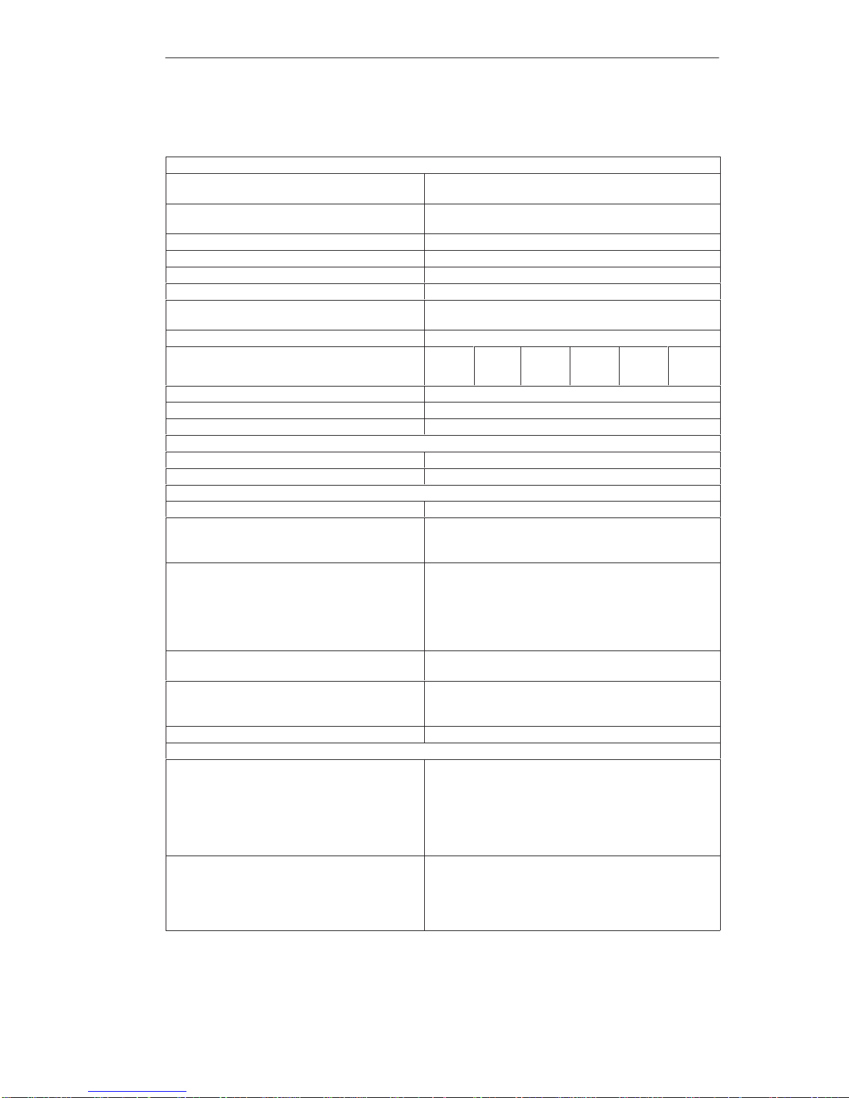
1.1 Technical Specifications
General Information
Dimensions
SIMATIC PC BI45
(W x H x D in mm)
385 x 295 164 mm
Dimensions
SIMATIC PC FI45
(W x H x D in mm)
483 (19”) x 310 (7HE) x 184 mm
W eight of SIMATIC BI45 approx. 11 kg
W eight of SIMATIC FI45 approx. 11 kg
Line voltage (UN) 120 VAC (93 to 132 VAC), or 240 VAC (187 to 264 VAC)
Line voltage frequency 50/60 Hz (47 to 63 Hz)
Brief voltage interruption acc. to NAMUR max. 20 ms at o.85 U
N
(max. 10 events per hour; recovery time at least 1 second)
Max. power consumption 220 W
Max. current delivery (DC) *1 +5 V
20 A
+3.3 V
10 A
+12 V
8 A
-12 V
0.5 A
-5 V
0.5 A
aux. 5 V
0.05 A
Noise emission < 50 dB (A) to DIN 45635
Degree of protection for SIMA TIC PC BI45 IP20
Degree of protection for SIMA TIC PC FI45 IP65, front (with drive cover closed)
Safety
Protection class Protection class I to VDE 0106 T1: 1982 (IEC 536)
Safety requirements IEC 950/09.91 corr. to EN 60950
Electr omagnetic Compatibility (EMC)
Emitted interference EN 55022 Class B
Noise immunity:
Line-fed interference on supply lines
+- 2 kV (to IEC 1000-4-4:1995; burst)
+- 1 kV (to IEC 1000-4-5:1995; surge symm)
+- 2 kV (to IEC 1000-4-5:1995; surge unsymm)
Noise immunity on process, measuring, and control
lines
+- 1 kV (to IEC 1000-4-4:1995; burst; length < 3m)
+- 2 kV (to IEC 1000-4-4:1995; burst; length > 3m)
+- 1 kV (to IEC 1000-4-4:1995; surge symm;
length > 3m)
+- 2 kV (to IEC 1000-4-4:1995; surge unsymm;
length > 3m)
Noise immunity to discharges of static electricity +- 6 kV contact discharge (to IEC 1000-4-2:1995)
+- 8 kV air discharge (to IEC 1000-4-2:1995)
Noise immunity to high-frequency radiation 10 V/m 80-1000 Mhz, 80% AM (to ENV 50140:1993)
10 V/m 900 Mhz, 50% ED (to ENV 50204:1995)
10 V 9 KHz-80 MHz
Magnetic field 30 A/m 50 Hz
Ambient Conditions
Temperature
- operation
- storage/transport
- gradient
Tested to DIN EN 60068-2-2:1994, DIN IEC 68-2-1,
DIN IEC 68-2-14,
+ 5°C to +45°C
-20°C to +60°C
Max. 10 degrees C/h (no condensation)
Relative humidity
- operation
- storage/transport
Tested to DIN IEC 68-2-3, DIN IEC 68-2-30,
DIN IEC 68-2-56
5 % to 85 % at 25°C (no condensation)
5 % to 95 % at 25°C (no condensation)
System Unit
Page 9
1-3
SIMA TIC PC BI45/FI45 PII, Technical Description
C79000-G7076-C794-03
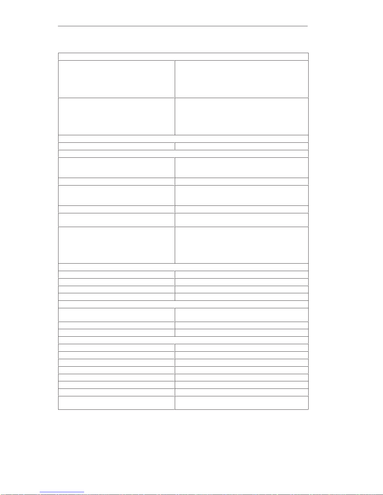
Mechanical Specifications
Vibration
- operation
- CD-ROM operation
- transport
Tested to DIN IEC 68-2-6
10 to 58 Hz: 0.075 mm, 58 to 500 Hz: 9.8 m/s
2
10 to 38 Hz: 0.0375 mm, 38 to 500 Hz: 2 m/s
2
5 to 9 Hz: 3.5 mm, 9 to 500 Hz: 9.8 m/s
2
Shock
- operation
- CD-ROM operation
- transport
Tested to DIN IEC 68-2-29
50 m/s
2
, 30 ms
50 m/s
2
, 11 ms
250 m/s
2
, 6 ms
Special Features
Quality assurance to ISO 9001
Motherboard
Processor Pentium II 1st level cache 16 Kbytes data memory,
16 Kbytes command memory
2nd level cache 512 Kbytes
Internal processor cache 2 x 16 Kbytes first level, 512 Kbytes second level
Main memory BI45: 32Mbytes
FI45: 64Mbytes
Max. 384 Mbytes
Second level cache 512 Kbytes integrated
Free expansion slots 1 ISA long, 1 ISA short (max. 165 mm)
2 PCI short (max. 165 mm), 1 x shared ISA/PCI long
– Max. admissible power consumption per ISA
slot
– Max. admissible power consumption per PCI slot
– In total (all slots):
5V 2A, 12V 0.3A, -12 V 0.05A, -5V 0.05A
5V 2A, 12V 0.5A, –12V 0.1A, -5V 0.05A
5V 10A, 12V 3A, –12V 0.5A, -5V 0.1A must not be
exceeded
Drives
Floppy disk drive 3.5” (1.44 Mbytes)
Hard disk drive 3.5” EIDE, ATA 33
CD-ROM drive 20x EIDE, 650 Mbytes, overall height 12.7 mm
Interfaces EIDE (primary and secondary , ATA 33)
Graphics
Graphics chip XGA-LCD-Controller Chips and T echnologies with
Windows accelerator on the PCI bus.
Graphics memory 2 Mbytes DRAM EDO 60 ns
Resolutions/frequencies/colors CRT: to 1280 x 1024 / 75 Hz / 65535 colors
LC Display (only for FI45)
Display type active TFT , color
Display size 270 x 203 mm (13.3”)
Picture resolution 1024 x 768 (XGA)
Colors 65536 (from 162.144)
Contrast 100:1
Brightness 150 cd/m
2
Response time 30/50 ms (t
rise/tfall
)
Permitted fault locations high/low level: < 12/25 spots
green high level: < 5 spots
System Unit
Page 10

1-4
SIMA TIC PC BI45/FI45 PII, Technical Description
C79000-G7076-C794-03
Interfaces
COM1 Serial port 1 (V.24 / TTY), 25-pin sub D socket connector
COM2 Serial port 2 (V.24), 9-pin sub D socket connector
LPT1 Parallel port (standard and EPP mode)
Interface for printer with parallel port
VGA VGA interface, for external monitor
Keyboard PS/2 keyboard interface
BI45: on the box
FI45: on the box and at the front
Mouse PS/2 mouse port
MPI/DP Interface, optically isolated *2 9-pin sub D socket connector, screw-type locking
For SIMATIC MPI or PROFIBUS DP networks (CP 5611
compatible)
Data signalling rate 9.6 Kbps to 1.5 Mbps, software-selectable
Operating mode Isolated*: Data lines A, B
Control lines RTS_AS, RTS_PG
5V supply voltage (max. 90 mA)
Ground connection: MPI/DP connector cable shield
Physical interface RS485, optically isolated
Memory address area Resources are assigned via PCI-PNP
Interrupts Resources are assigned via PCI-PNP
Relay interface,
only in conjunction with SafeCard
Connection of a signaling device to a SafeCard monitoring
module (see SafeCard description in the section on
“Monitoring Module”).
Function Displays
BI45 Floppy disk access (floppy disk drive on the side of the box)
CD access (CD drive on the side of the box)
FI45 POWER
Floppy drive
MPI/DP
RUN (in conjunction with SafeCard)
TEMP (in conjunction with SafeCard)
Floppy disk access (floppy disk drive behind the drive cover)
CD access (CD drive behind the drive cover)
*1 Maximum of 150 W in total, with +5V and +3.3V the sum of 100W must not be exceeded. +12V can be loaded with
11A for a maximum of 10 seconds.
*2 Optically isolated within the safety extra-low voltage circuit (SEL V)
System Unit
Page 11
1-5
SIMA TIC PC BI45/FI45 PII, Technical Description
C79000-G7076-C794-03
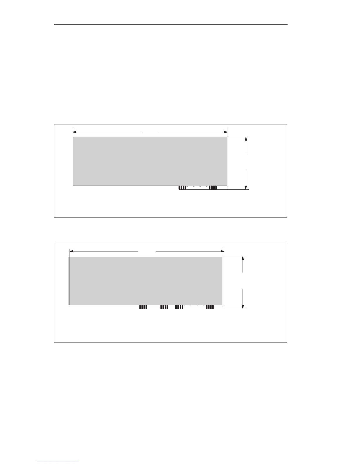
1.2 Maximum Dimensions of Expansion Modules
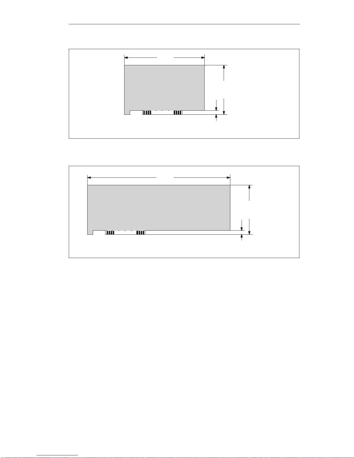
The SIMATIC PC BI45/FI45 is designed for modules according to AT/PCI
specifications. The size of the modules should not exceed the dimensions
indicated. If the given height is exceeded, this may cause contacting
problems, functional disorders, or difficulties with installation. The figures
below illustrate two cards with full AT/PCI overall length. Individual slots
may require different card dimensions.
340.7
106.7
A31 A1
(All dimensions in mm)
(13,41)
(4,2)
(All dimensions ( ) in inches)
Figure 1-1 XT Module
340.7
121.92
A31 A1
(All dimensions in mm)
C18 C1
(13,41)
(4,8)
(All dimensions ( ) in inches)
Figure 1-2 AT Module
Information on
Modules
System Unit
Page 12
1-6
SIMA TIC PC BI45/FI45 PII, Technical Description
C79000-G7076-C794-03
174.63
106.68
8.19
(All dimensions in mm)
(6,87)
(4,2)
(0,32)
(All dimensions ( ) in inches
Figure 1-3 Small PCI Module (5 V)
312
106.68
8.19
(All dimensions in mm)
(12,28)
(4,2)
(0,32)
(All dimensions ( ) in inches)
Figure 1-4 Large PCI Module (5 V)
Large PCI modules have to be equipped with a so-called extender (usually
included with large PCI modules) which serves to guide them along the rails
of the ventilator case. The extender guides large PCI modules along the rails
of ISA modules.
Information on
Large PCI Modules
System Unit
Page 13
1-7
SIMA TIC PC BI45/FI45 PII, Technical Description
C79000-G7076-C794-03
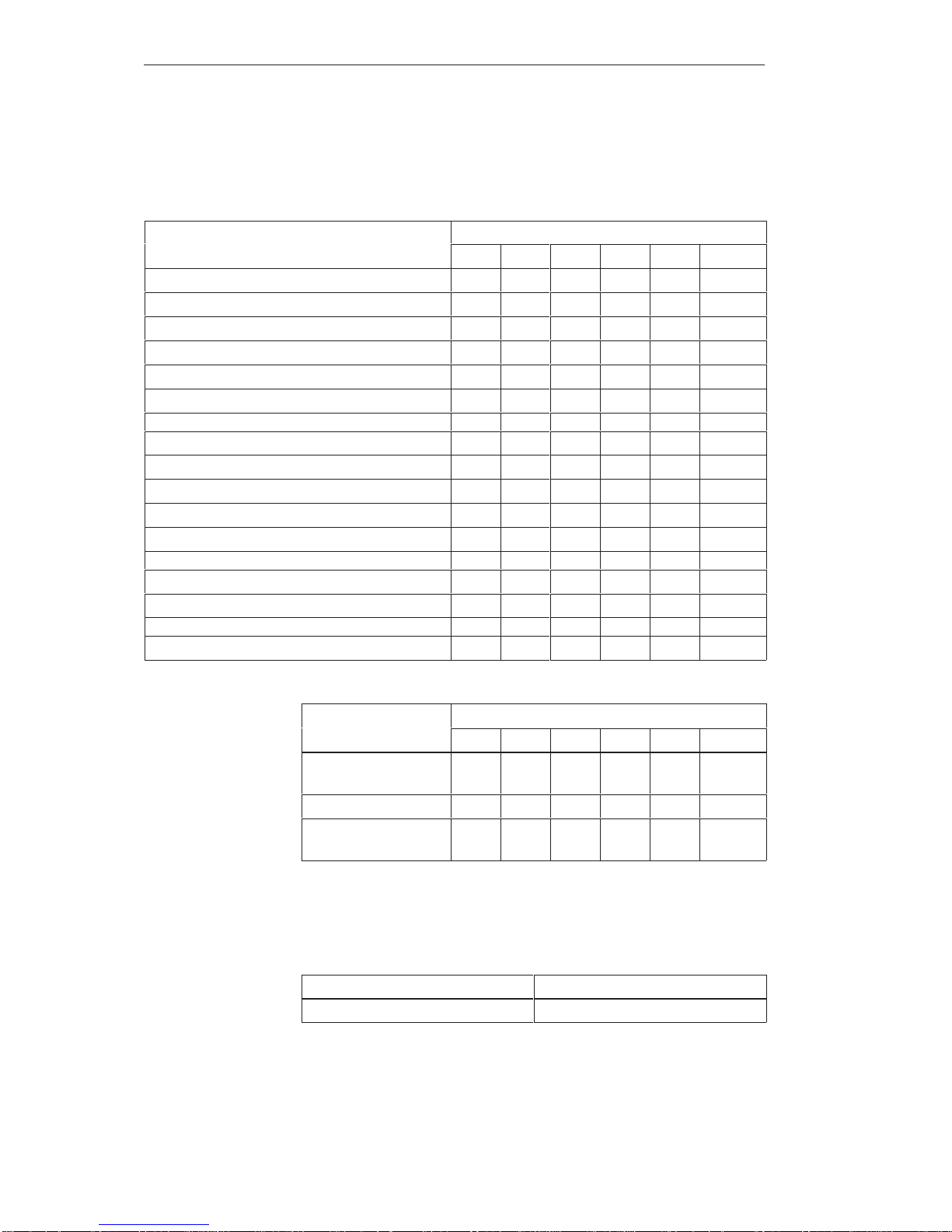
1.3 Power Requirements of the Components (Maximum Values)
Component Voltage
+5V +3.3V +12V –5V –12V AUX5V
Pentium II motherboard 7 A 1.5 A 0.1 A 0.01 A 0.02 A 0.05 A
Floppy disk drive 0.45 A
Hard disk 0.6 A 0.66 A
CD-ROM drive 0.7 A
Fan 0.3 A
Sum BI45 (basic configuration) 8.75 A 1.5 A 1.06 A
0.01 A
0.02 A
0.05 A
Keyboard controller (only with FI45) 0.15 A
Touch pad (only with FI45) 0.05 A
TFT display (only with FI45) 0.7 A
Inverter (incl. backlight, only with FI45) 0.5 A
Sum BI45 (max. for basic configuration) 8.95 A 2.2 A 1.56 A
0.01 A
0.02 A
0.05 A
ISA slots (sum for 3 slots) 5 A
2 A 0.3 A
0.3 A
PCI slots (sum for 3 slots) 5 A
2 A 0.2 A
0.2 A
Sum (max. for maximum configuration) 20 A 10 A 8 A
0.5 A
0.5 A
0.05 A
Component
Voltage
+5V +3.3V +12V –5V –2V AUX5V
WinAC FI Station Pro
(SlotPLC)
0.35 A 1.3A
Direct key module 0.5 A
‘SafeCard’ monitoring
module
0.35A 0.05 A
Due to thermal stress, the maximum capacity of the power supply is
restricted to:
Power supply Restriction
Standard power supply (220 W) maximum load 150 W
Basic System
Options
Restrictions on
Power Supply
System Unit
Page 14
1-8
SIMA TIC PC BI45/FI45 PII, Technical Description
C79000-G7076-C794-03
1.4 Removing and Installing Components
The system unit is designed to enable any necessary maintenance work to be
carried out quickly and at low cost.
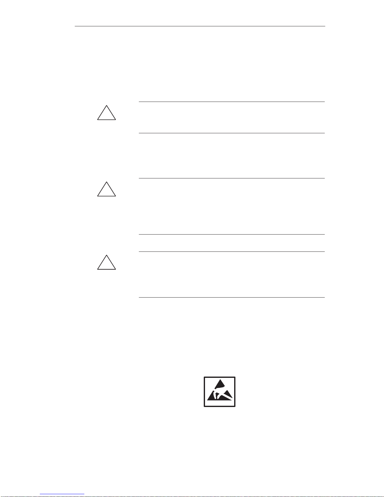
!
Warning
Please read the warnings at the front of the User’s Guide before you open the
housing of the system unit.
Do not open the housing unless you need to install or remove
components, or to replace the battery.
Write down your configuration parameters before starting the procedure.
!
Caution
Risk of damage to the unit!
Note that only qualified personnel should be allowed to work on the open
unit, so the warranty on the device is not affected. Authorized SIEMENS
maintenance and repair centers offer you a specialist maintenance service.
The User’s Guide contains the addresses.
!
Caution
The electronic components of the printed boards are extremely sensitive to
electrostatic discharge. When handling the boards, you must take appropriate
safety precautions. These are set out in the guidelines for electrostatically
sensitive components (ESD guidelines) at the end of this manual.
All technical specifications and licenses apply only to expansion functions
approved by SIEMENS. No liability can be assumed for functional
constraints caused by the use of devices and components of other
manufacturers.
The following sign warns that electrostatically sensitive modules are present.
Please read the ESD guidelines.
Prerequisites
Limitation of
Liability
System Unit
Page 15

1-9
SIMA TIC PC BI45/FI45 PII, Technical Description
C79000-G7076-C794-03
Before opening the unit, you should read the following rules carefully:
Before you disconnect the power supply cable, discharge any electrostatic
charge on your body. You can do this by touching metallic parts, such as
screws, on the rear panel of the PG.
Discharge any electrostatic charge from tools that you are using.
Wear a grounding wrist strap if you are handling components.
Leave components and modules in their packaging until you are ready to
install them.
Disconnect the PC from its power supply before plugging in or removing
any modules or components.
Touch components and modules only on their edges. Above all, do not
touch the connecting pins and printed conductors.
Do not operate the PC with the cover open.
Use a suitable crosstip or TORX screwdriver to remove or install
components.
Before Opening
the Unit
Tools
System Unit
Page 16
1-10
SIMA TIC PC BI45/FI45 PII, Technical Description
C79000-G7076-C794-03
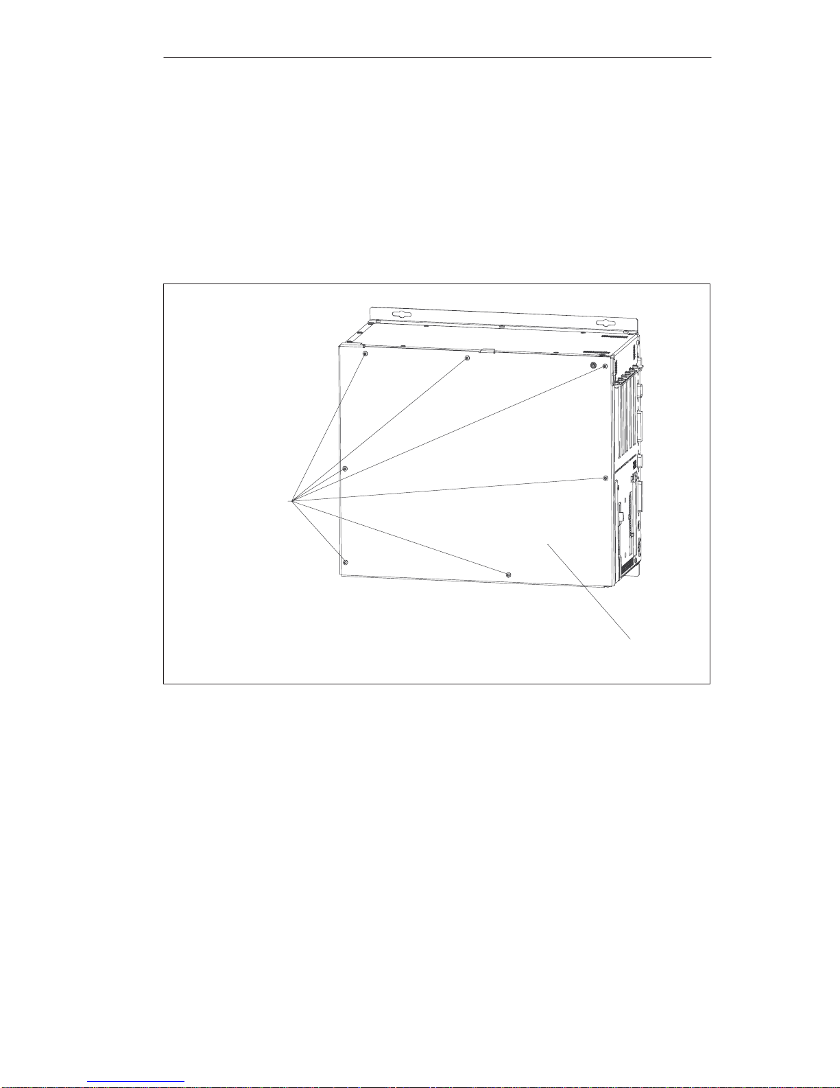
1.4.1 Opening and Closing the System Unit of the BI45
Close the application you are using.
Remove the diskette or CD-ROM from the drive.
Pull out the power supply connector.
Remove the PC from its support.
Release the seven screws on the cover of the unit.
Fastening screws
Cover of the unit
Figure 1-5 Opening the System Unit of the BI45
System Unit
Page 17
1-11
SIMA TIC PC BI45/FI45 PII, Technical Description
C79000-G7076-C794-03
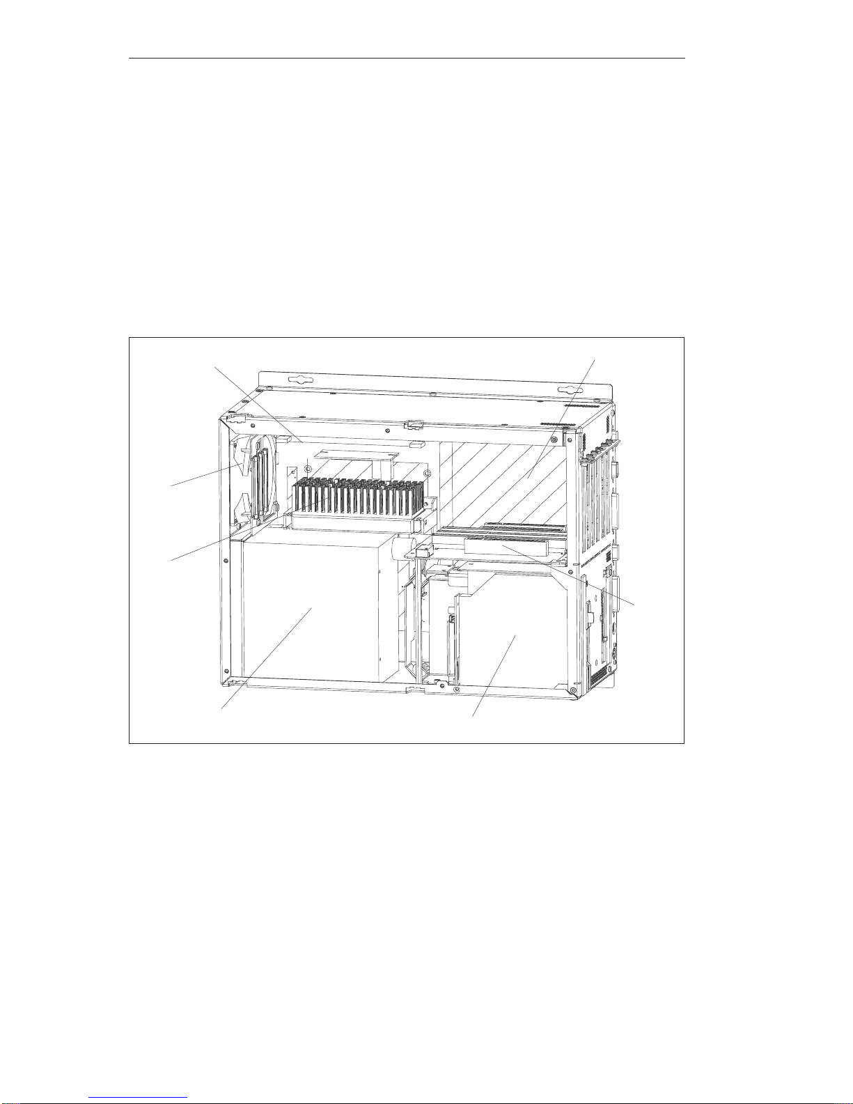
When the cover of the unit is removed, you see the following
components/function units:
– Power supply
– Floppy disk drive and CD-ROM drive
– Motherboard
– Bus board
– Fan
– Processor
– RAM memory module(s)
Power supply
Floppy disk drive and CD-ROM drive
Motherboard
Fan
Processor
RAM memory module
Bus
board
Figure 1-6 Function Units when the BI45 is Opened
System Unit
Page 18
1-12
SIMA TIC PC BI45/FI45 PII, Technical Description
C79000-G7076-C794-03
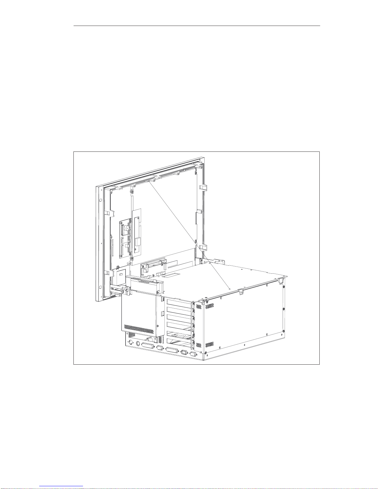
1.4.2 Lowering the FI45 System Box Away from the Front Panel
S Close the application you are using.
S Remove the diskette or CD-ROM from the drive.
S Pull out the power supply connector.
S Release the six screws used to fasten the cover to the front of the unit.
S Tilt the system box about 5_ towards you and then pull it away from the
front panel until it reaches the latched position of the hinge.
S Now lower the system box down completely. A wire holds the system box
in place at a 90_ angle.
Figure 1-7 Lowering the System Unit of the FI45
System Unit
Page 19
1-13
SIMA TIC PC BI45/FI45 PII, Technical Description
C79000-G7076-C794-03
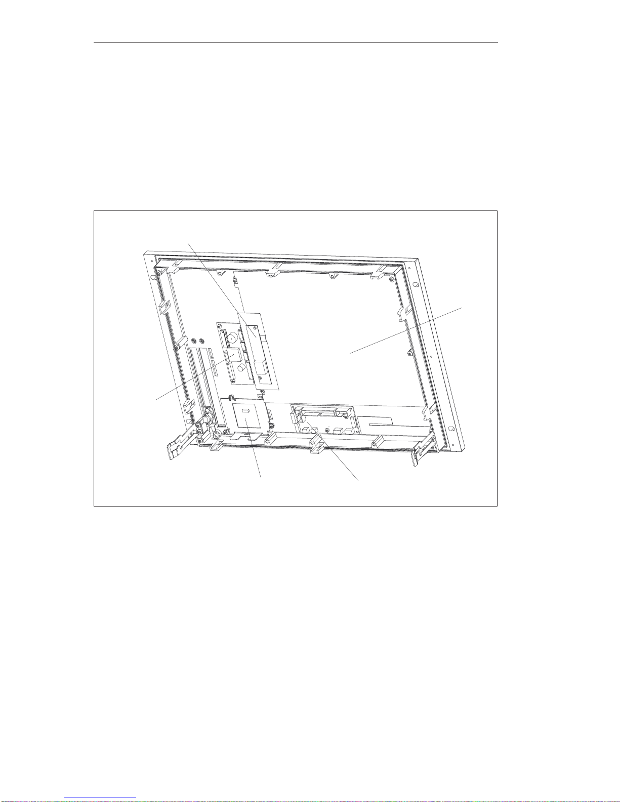
When the system box has been lowered, you will see the following
components/function units in the front panel:
– LC display
– Inverter module
– Keyboard controller
– Front adapter module
– Touch pad controller module
LC display
Front adapter moduleTouch pad controller module
Keyboard controller
Inverter module
Figure 1-8 Function Units in the Front Panel of the FI45
System Unit
Page 20
1-14
SIMA TIC PC BI45/FI45 PII, Technical Description
C79000-G7076-C794-03
1.4.3 Removing the System Box of the FI45 from the Front Panel
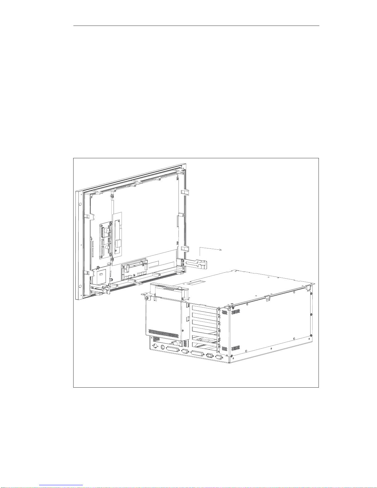
Lower the system box of the FI45 away from the front panel as described
in Section 1.4.2.
Disconnect the mains supply to the LC display by pulling the connector
carefully towards the front frame.
Disconnect the ribbon cable from the front adapter module.
Unhook the safety wire from the system box.
Lift the system box upwards and out so that the hinge is released from its
latched position; then pull the system unit further away from the front.
The system unit is now isolated from the front unit.
Figure 1-9 Removing the System Unit of the FI45
System Unit
Page 21
1-15
SIMA TIC PC BI45/FI45 PII, Technical Description
C79000-G7076-C794-03
1.4.4 Opening and Closing the System Unit of the FI45
Remove the system box from the front panel as described in Section
1.4.3.
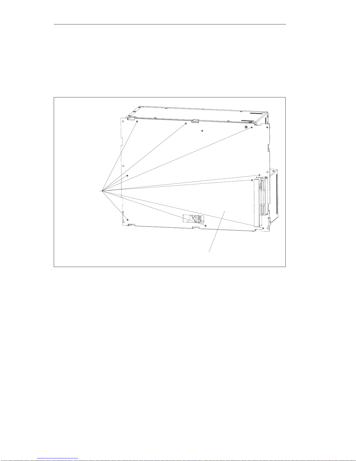
Release the seven screws on the cover of the unit.
Partition plate
Fastening screws
Figure 1-10 Opening the System Unit of the FI45
System Unit
Page 22
1-16
SIMA TIC PC BI45/FI45 PII, Technical Description
C79000-G7076-C794-03
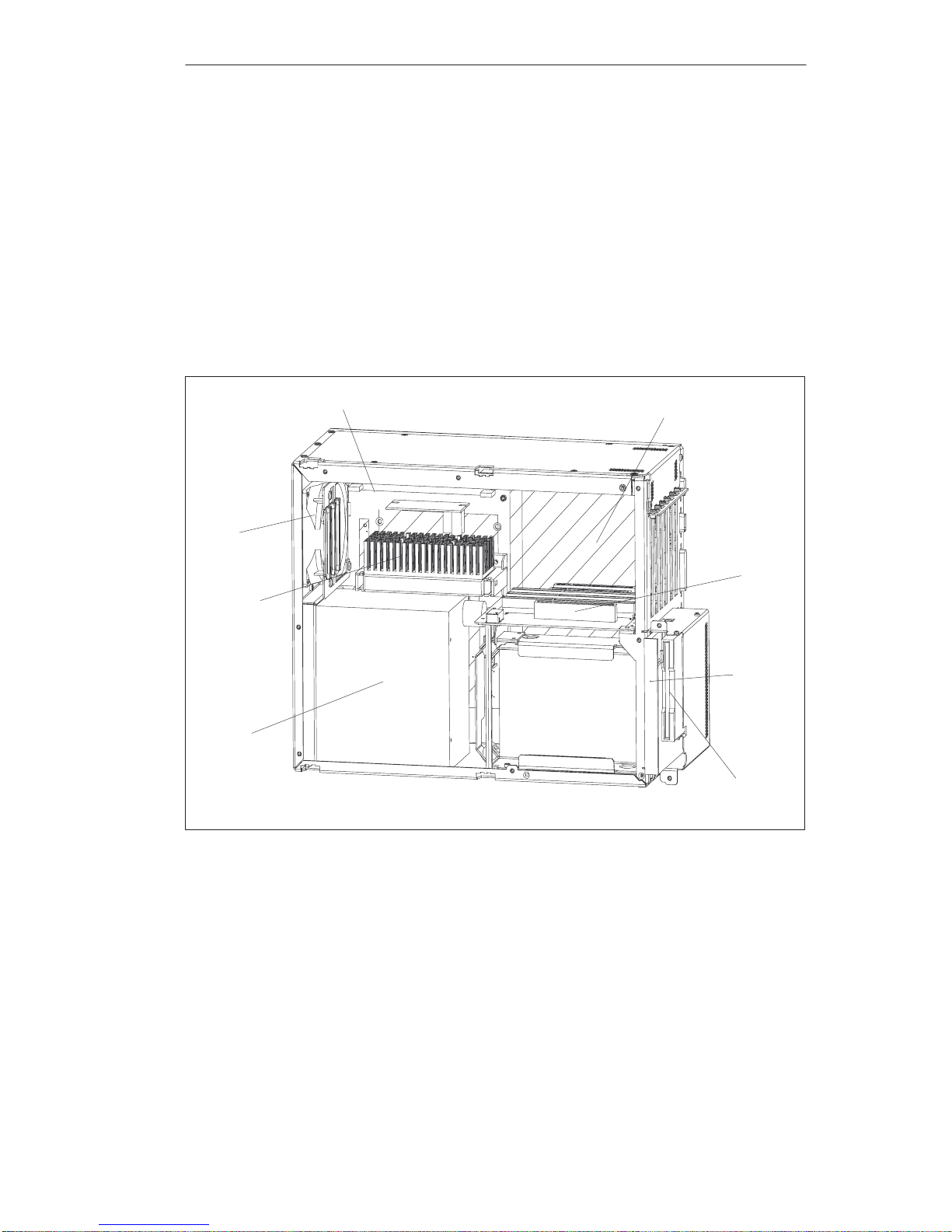
When the cover of the unit is removed, you see the following components/
function units:
– Power supply
– Floppy disk drive and CD-ROM drive
– Motherboard
– Bus board
– Fan
– Processor
– RAM memory module(s)
MotherboardRAM memory module
Fan
Processor
Power supply
Bus board
Floppy disk drive
CD-ROM
drive
Figure 1-11 Function Units when the FI45 is Opened
System Unit
Page 23
1-17
SIMA TIC PC BI45/FI45 PII, Technical Description
C79000-G7076-C794-03
1.4.5 Removing and Installing Expansion Modules
Close the application you are using.
Remove the diskette or CD-ROM from the drive.
Pull out the power supply connector.
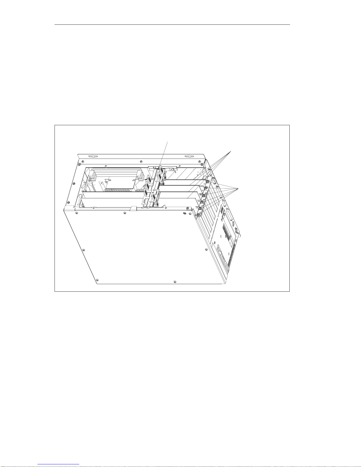
Release the 6 screws on the cover of the unit. (If necessary, remove the
BI45 from its support or lower the system box away from the front panel
as described in Section 1.4.2).
Module retainers
Expansion modules
Fastening screws
for the expansion
modules
Figure 1-12 Opening the Cover of the Unit
First you must remove the crossbeam on which the modules are mounted.
When you bend the notched spring clips inwards a little, the snap-in
lockings can be released.
Grip the crossbeam, push it approximately 1cm to the left, and then lift it
out with the the module retainers.
System Unit
Page 24

1-18
SIMA TIC PC BI45/FI45 PII, Technical Description
C79000-G7076-C794-03
To install the retainers, proceed in reverse order.
Disconnect all mains connections to the module.
Undo the screw which fastens the expansion module to the side of the
system box.
Pull the module carefully out of the slot – without tilting it.
Set the DIP switches and jumpers of the new module according to the old
module (providing that the release levels of the two modules correspond,
if the release levels are not the same, you must consult the relevant
module documentation).
To install the new module, proceed in reverse order. After
installing/exchanging an expansion module, the retainers may need to be
readjusted. To do this, proceed as follows:
Insert the sliding element at the top and push it down until it covers the
module. Then guide the module into the notch.
!
Caution
Do not exert pressure on the module. This means that you should not push
down or force the retainers in any way.
Detach the part of the sliding element which juts out by scratching a
notch in the top of the sliding element with a knife and then bending it
over to break it off.
System Unit
Page 25
1-19
SIMA TIC PC BI45/FI45 PII, Technical Description
C79000-G7076-C794-03
1.4.6 Removing and Installing the Power Supply Unit
S Open the system unit as described in Section 1.4.1 (BI45) or Section 1.4.4
(FI45).
S Release the three screws with which the bent clips of the power supply
support are fastened to the system unit.
S Pull the power supply unit and its support right out of the system unit.
S Disconnect the cables from the motherboard, the hard disk, and the bus
expansion unit, and write down their previous connections.
S Release the four screws with which the power supply support is attached
to the power supply unit.
To install the power supply unit, proceed in reverse order.
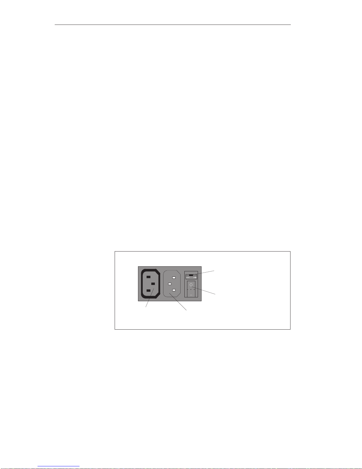
The standard power supply for the SIMATIC PC is set for 115/230V
networks. The voltage selection switch is located at the rear of the system
unit below the ventilation slots.
You must ensure that the supply voltage set at the voltage selection switch
corresponds to the local supply voltage.
If the voltage specified at the selection switch does not match the local
supply voltage, you must change the voltage selection switch so that you can
read the voltage value set below the green triangle on the right. Use a small,
flat screwdriver to lever out the part with the voltage values and reinsert it in
the appropriate position.
Power supply
connector (output)
Power supply
connector (input)
On/off switch
B
Supply voltage
selection switch
Figure 1-13 Connecting the Supply V oltage
Changing the
Supply Voltage
Selecting the
Supply Voltage
System Unit
Page 26
1-20
SIMA TIC PC BI45/FI45 PII, Technical Description
C79000-G7076-C794-03
!
Caution
Damage may be caused to the device!
Operating the PC with the wrong supply voltage setting may damage the
device. The same voltage is applied to the supply voltage output as to the
supply voltage input.
Please observe the specifications made by the monitor manufacturer when
operating the monitor.
The following table lists the permissible input currents for the monitor:
Input voltage 120 V / 240 V ± 10%
Input current 8A / 4A
Output voltage Equal to input voltage
Max. output current 3A / 1.5A
!
Caution
You must remove the power supply connector before changing the supply
voltage.
Operating a power supply unit set to 115V in conjunction with a 230V
network may cause serious damage to the PC.
System Unit
Page 27

1-21
SIMA TIC PC BI45/FI45 PII, Technical Description
C79000-G7076-C794-03
1.4.7 Removing and Installing the Bus Board
First remove all expansion modules as described in Section 1.4.5.
Open the system unit as described in Section 1.4.1 (BI45) or Section 1.4.4
(FI45).
Remove the power supply connection from the bus board.
Release the two screws on the bus board.
Lift the bus board out of the connector to the motherboard.
To install the bus board, proceed in reverse order.
1.4.8 Removing and Installing the Fan
First remove all expansion modules as described in Section 1.4.5.
Remove the power supply connection for the fan from the motherboard
(or the SafeCard module, if present).
The fan is fastened to the system unit with four plastic rivets. Remove the
plastic rivets by pressing the pin out from behind.
Take out the fan and the metal plate to which the guide rails are attached.
Detach the plate with the guide rails by releasing the four plastic rivets.
To install the fan, proceed in reverse order.
System Unit
Page 28

1-22
SIMA TIC PC BI45/FI45 PII, Technical Description
C79000-G7076-C794-03
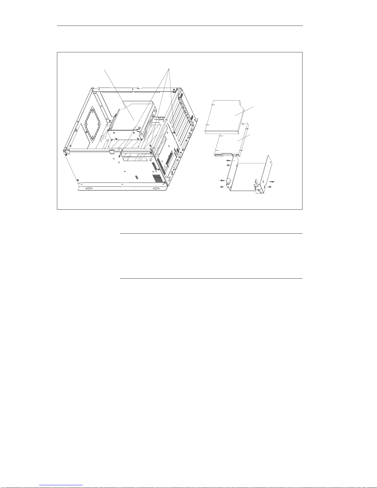
1.4.9 Removing and Installing a Floppy Disk Drive or CD-ROM Drive for
the BI45
Open the system unit as described in Section 1.4.1.
Lay the system unit face up on a flat surface.
The floppy disk drive and the CD-ROM drive are fitted in a single
support in the system unit.
Release the three screws with which the support is fastened to the system
unit.
Remove the connection cables and lift the support carefully out of the
system unit.
!
Caution
Before you remove the flexible cable from the floppy disk drive, you must
first release the interlock on the port.
The floppy disk drive is fastened to the support with three screws. Release
these screws and pull the drive out of the support.
The CD-ROM drive is fastened to the support with three screws. Release
the screws and pull the drive out of the support.
To install the drives, proceed in reverse order.
System Unit
Page 29
1-23
SIMA TIC PC BI45/FI45 PII, Technical Description
C79000-G7076-C794-03
CD-ROM drive
Floppy disk drive
Drive support Fastening screws for drive support
Figure 1-14 Floppy Disk/CD-ROM Drive Support on the BI45
Note
The floppy disk/CD support can also be installed in the system unit at a 90
angle. This is necessary if the unit is installed with the network connection at
the top. The floppy disk drive may not be operated with the opening for the
diskettes face up or face down.
System Unit
Page 30

1-24
SIMA TIC PC BI45/FI45 PII, Technical Description
C79000-G7076-C794-03
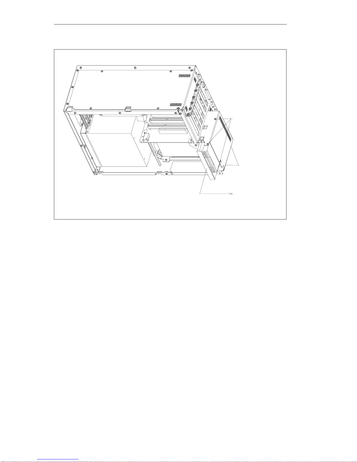
1.4.10 Removing and Installing a Floppy Disk Drive or CD-ROM Drive for
the FI45
Open the system unit as described in Section 1.4.4.
Lay the system unit on a flat surface with the opening face up.
The floppy disk drive and the CD-ROM drive are fitted in a single
support in the system housing.
Raise the support approximately 1cm and lower it to one side of the
system unit.
Remove the connecting cables.
!
Caution
Before you remove the flexible cable from the floppy disk drive, you must
first release the interlock on the port.
The floppy disk drive is fastened to the support with three screws. Release
the screws and pull the drive out of the support.
The CD-ROM drive is fastened to the support with two screws. Release
the screws and pull the drive out of the support.
To install the drives, proceed in reverse order.
System Unit
Page 31
1-25
SIMA TIC PC BI45/FI45 PII, Technical Description
C79000-G7076-C794-03
Fastening screws for
floppy disk drive
Fastening screws for
CD-ROM drive
Figure 1-15 Floppy Disk/CD-ROM Drive Support for the FI45
System Unit
Page 32
1-26
SIMA TIC PC BI45/FI45 PII, Technical Description
C79000-G7076-C794-03
1.4.11 Removing and Installing the Hard Disk of the BI45/FI45
If you are using the BI45, remove the floppy disk/CD-ROM drive support
as described in Section 1.4.9.
If you are using the FI45, lower the floppy disk/CD-ROM drive support to
one side of the system unit as described in Section 1.4.10.
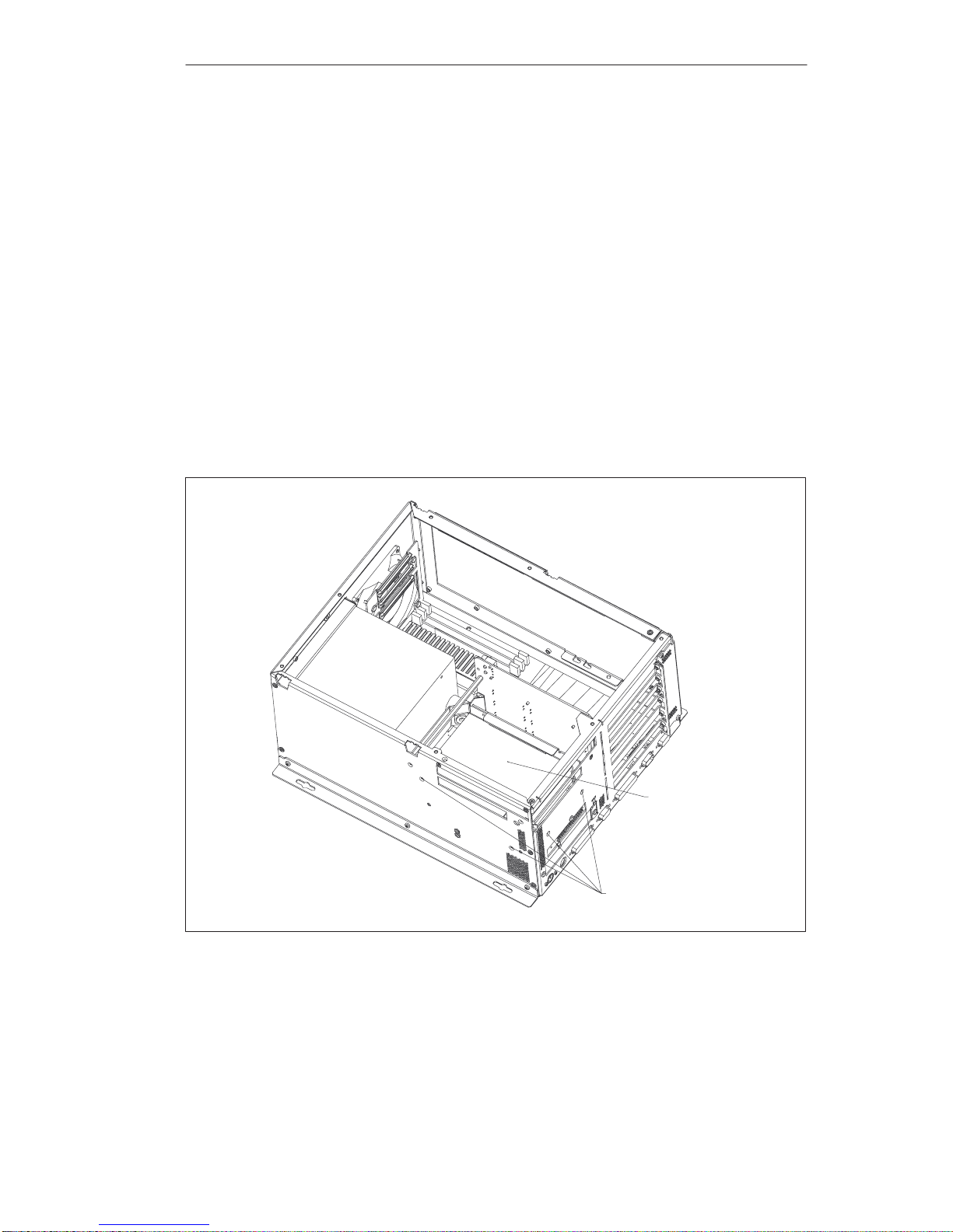
Release the four screws with which the hard disk support is fastened to
the system unit.
Remove the connecting cables and lift the support carefully out of the
system unit.
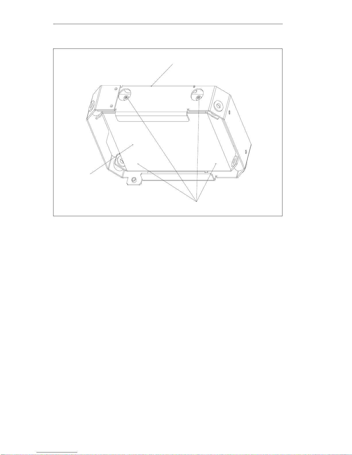
Release the four screws with which the hard disk is fastened to the
vibration-damped part of the support.
Take the hard disk out out of the support.
To install the drive, proceed in reverse order.
Hard disk support
Fastening screws for
hard disk support
Figure 1-16Removing the Hard Disk Support
System Unit
Page 33
1-27
SIMA TIC PC BI45/FI45 PII, Technical Description
C79000-G7076-C794-03
Hard disk support
Fastening screws
Hard disk drive
Figure 1-17 Removing the Hard Disk Drive from the Support
System Unit
Page 34
1-28
SIMA TIC PC BI45/FI45 PII, Technical Description
C79000-G7076-C794-03
1.4.12 Removing and Installing the Motherboard
Open the system unit as described in Section 1.4.1 (BI45) or Section 1.4.4
(FI45).
Remove the power supply as described in Section 1.4.6.
Remove the bus board as described in Section 1.4.7.
Remove the fan as described in Section 1.4.8.
Remove the support for the floppy disk drive and the CD-ROM drive as
described in Section 1.4.9 (BI45) or Section 1.4.10 (FI45).
Remove the hard disk support as described in Section 1.4.11.
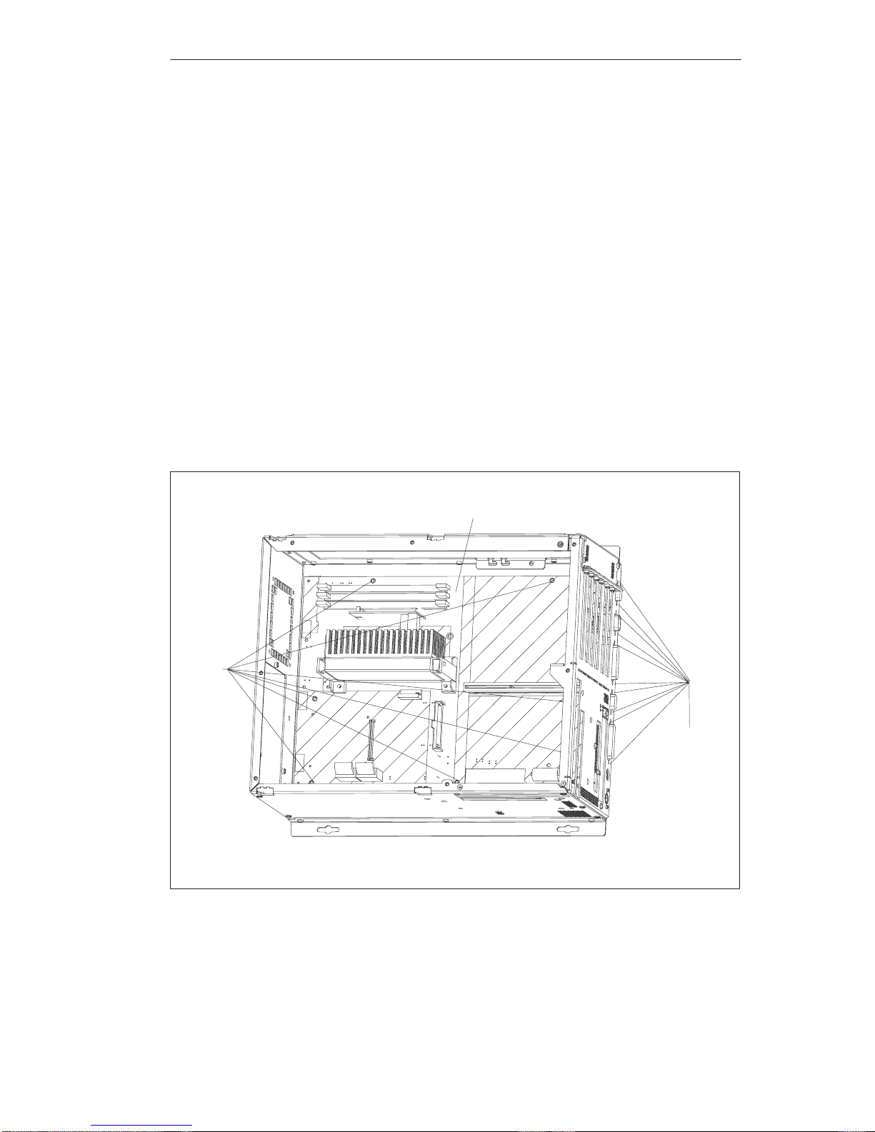
The motherboard is fastened to the system unit with seven screws.
Release these screws.
The motherboard is fastened to the side of the system unit with 10
hexagonal socket screws. Undo these socket screws and remove the
motherboard.
To install the motherboard, proceed in reverse order.
Hexagonal
socket screws
Motherboard
Fastening
screws
Figure 1-18 Removing the Motherboard
System Unit
Page 35

1-29
SIMA TIC PC BI45/FI45 PII, Technical Description
C79000-G7076-C794-03
1.4.13 Removing and Installing the Membrane Keyboard or Front
Components of the FI45
After the device has been installed, the membrane keyboard or front
components can be exchanged from the front. Proceed as follows:
Close the application you are using.
Open the cover of the disk drive and remove the diskette or CD-ROM.
Pull out the mains connector.
Release the 10 screws with which the membrane keyboard is fastened to
the front frame.
Grip the cover of the disk drive carefully and pull the membrane
keyboard forwards and off.
!
Caution
There is nothing to prevent the keyboard from falling.
Unplug the 40-pin connector from the front adapter module and
disconnect the interface cable carefully from the display.
Remove the membrane keyboard and the front components mounted on it.
To install the membrane keyboard, proceed in reverse order.
System Unit
Page 36

1-30
SIMA TIC PC BI45/FI45 PII, Technical Description
C79000-G7076-C794-03
1.4.14 Removing and Installing the Keyboard Controller for the FI45
Lower the system box of the FI45 away from the front as described in
Section 1.4.2 or remove the membrane keyboard as described in Section
1.4.13.
Loosen the two screws and then remove the support with the inverter
module.
Remove the two connection cables for the membrane keyboard.
!
Caution
Before you remove the connecting cables, release the interlocks on the ports
so that the contacts of the connecting cables are not damaged.
Before you unplug all the other connectors, write down their previous
connections.
Undo the two remaining screws; you can then lift out the keyboard
controller board.
To install the keyboard controller, proceed in reverse order.
1.4.15 Removing and Installing the Inverter Module for the FI45
Lower the system box of the FI45 away from the front panel as described
in Section 1.4.2 or remove the membrane keyboard as described in
Section 1.4.13.
Before you unplug all the connectors, write down their previous
connections.
Undo the two screws and remove the support with the inverter module.
The inverter module is fastened to the support with two plastic rivets.
Remove the rivets, by pressing the pin out from behind.
To install the inverter module, proceed in reverse order.
!
Caution
When installing the module, do not forget to place the insulating foil
between the inverter module and the metal plate.
System Unit
Page 37

1-31
SIMA TIC PC BI45/FI45 PII, Technical Description
C79000-G7076-C794-03
1.4.16 Removing and Installing the Display for the FI45
Lower the system box of the FI45 away from the front panel as described
in Section 1.4.2 or remove the membrane keyboard as described in
Section 1.4.13.
Release the two screws with which the support for the inverter module is
mounted.
Before you unplug all the connectors, write down their previous
connections.
Release the four screws with which the display is secured and then
remove the display.
To install the display, proceed in reverse order.
1.4.17 Removing and Installing the Touch Pad for the FI45
Remove the membrane keyboard as described in Section 1.4.13.
Release the three screws on the installation plate with which the touch
pad module is fastened to the membrane keyboard.
Remove the installation plate and the copper-colored sheet-metal spring
underneath.
Take out the touch pad module and detach the flexible cord (contact side
faces module).
To install the touch pad, proceed in reverse order.
1.4.18 Removing and Installing the Front Adapter Module for the FI45
Lower the system box of the FI45 away from the front panel as described
in Section 1.4.2, or remove the membrane keyboard as described in
Section 1.4.13.
Remove the two connection cables for the membrane keyboard and the
flexible cord which leads to the touch pad module.
!
Caution
Before you remove the connecting cables, release the interlocks on the ports
so that the contacts of the connecting cables are not damaged.
Before you unplug all the other connectors, write down their previous
connections.
Release the three screws; then you can remove the front adapter module.
To install the front adapter module, proceed in reverse order.
System Unit
Page 38

1-32
SIMA TIC PC BI45/FI45 PII, Technical Description
C79000-G7076-C794-03
1.5 Connecting the MPI/DP Interface
You can connect your IPC to PROFIBUS-DP networks via the optically
isolated *) MPI/DP interface. The connection is established via SINEC L2
components for stationary links or via an MPI connecting cable with a length
of 5 meters for non-stationary links (order no.: 6ES7001-0BF00-0AA0).
SINEC L2 components and MPI connecting cables are not included with the
IPC and have to be ordered separately. The MPI connecting cable (5m) can
only be employed for data transfer rates up to 187.5 Kbps.
To connect your IPC to a PROFIBUS-DP network, proceed as follows:
1. Switch off your IPC.
2. Plug the connecting cable (of the SINEC L2 components or the MPI
connecting cable) into the MPI/DP socket connector of your IPC and
tighten the connector by means of screw-type locking.
3. Switch on your IPC.
!
Caution
Risk of damage to the unit!
Before plugging in the connecting cables, you must discharge the
electrostatic charge of the cables and of your body by briefly touching a
grounded object (ESD guideline).
You can network up to 32 devices (PC, PG, PLC or DP components) via the
MPI/DP interface in one segment. The interconnection to the PROFIBUS-DP
segments is established via an optically isolated *) RS 458 port, which is part
of the interface.
Interconnect several PROFIBUS-DP segments via a repeater.
The entire PROFIBUS-DP network has a maximum capacity of 127 stations.
The data transfer rate of the MPI network is 187.5 Kbps. The data transfer
rate that can be achieved via MPI/DP interface in the PROFIBUS-DP
network ranges from 9.6 Kbps up to 1.5 Mbps.
Note
For further information on configuring a PROFIBUS-DP network please
refer to the “S7-300 Hardware Manual,” order no.: 6ES7030-0AA00-8AA0.
*) Optically isolated within SELV circuit
Connecting a
PROFIBUS-DP
Network via
MPI/DP Interface
PROFIBUS-DP
Network
System Unit
Page 39

1-33
SIMA TIC PC BI45/FI45 PII, Technical Description
C79000-G7076-C794-03
1.6 Point-to-Point Connections
In this section, you will learn how to connect your device to a programming
device or programmable controller using a point-to-point connection.
You can establish a point-to-point connection by connecting the SIMATIC
PC to a programming device or a programmable controller via:
A V.24 connection.
A TTY connection.
Reliable data transfer depends on several factors. The data transfer rate you
can achieve depends on the distance, the type of cable, the type of interface
and any interference present.
You can reduce interference by choosing the right transmission cable and
connecting it properly, and observing the following guidelines:
Use a shielded cable with a low surge impedance (< 130 W / km) and low
capacitance (< 90 pF/m). Twisted-pair cables enhance noise immunity
due to inductance. A low surge impedance results in reduced voltage
excursions and shorter charge reversal times. The larger the conductor
cross-section, the lower the surge impedance for the same length of cable.
The shorter the transmission link, the higher the maximum possible data
transfer rate.
If there is an active sender and an active receiver at the same end of the
transmission link, the sequence of access priority to the transmission
circuit must be taken into account in order to achieve the longest possible
transmission link.
Signal lines and power lines must not be run together. Signal lines must
be installed as far away as possible from strong interference sources
(for example, 400 V three-phase power cables).
The active TTY interface with 12 V no-load voltage has been tested on a
1000 m (3300 ft.) long cable at a transmission rate of 9600 bps in a
normal noisy environment (field strength < 3 V/m or 1 V/ft.). If a
shielded LiYCY 5x1x0.14 is used, reliable transmission is possible over a
distance of up to 1000 m (3300 ft.). The AS511 protocol (only one
transmitter at a time) was used for testing.
Note
The contaminating field of the interference source decreases exponentially
with the distance.
Point-to-Point
Connection
Suggestions for
Configuring TTY
(20 mA) Interfaces
Rules
System Unit
Page 40
1-34
SIMA TIC PC BI45/FI45 PII, Technical Description
C79000-G7076-C794-03
You can connect the BIxx/FIxx to a SIMATIC S5 programmable controller
via the COM1/TTY interface port.
Connect your BIxx/FIxx to a SIMATIC S5 programmable controller as
follows:
1. Switch off the BIxx/FIxx.
2. Plug the cable into the COM1/V.24 PLC interface port.
!
Caution
Risk of damage to the BIxx/FIxx!
The interface port may be damaged if you confuse the connections or use the
wrong connecting cables. Make sure the TTY cable of the BIxx/FIxx is
plugged into the COM1/TTY port and not into the LPT1 port.
Before plugging in the cables, you must discharge your body’s electrostatic
charge by briefly touching a grounded object (ESD guideline).
Use only the original cables to establish the connection to the programmable
controller.
The BIxx/FIxx and the programmable controller must be operated at the same
protective ground potential.
An adapter is available for connecting the programmable controller using
older standard cables.
Interface Link Connecting Cable Adapter
6ES5 734-2BD20
TTY interface
BIxx/FIxx to
SIMATIC S5
6ES5 731-1xxx0
15-pin
6ES5 731-6AG00
(COM1)
programmable
controller
6ES5 731-0xxx0
25-pin
6ES5 731-6AG00
In order to maintain a data transfer rate of 9600 bps up to a distance of over
1000 m (3300 ft), the receiving diode is connected to ground (reference) via
the connecting cable. Cables of various lengths are available under the Order
No. 6ES5 734-2xxx0 (xxx stands for the length in meters).
Connecting the
BIxx/FIxx to S5
Programmable
Controllers
Connecting the
BIxx/FIxx via an
Adapter
Higher Data
Transfer Rates at
Distances of up to
1000 m (3300 ft.)
System Unit
Page 41

1-35
SIMA TIC PC BI45/FI45 PII, Technical Description
C79000-G7076-C794-03
1.7 Error Diagnostics
Error Cause Remedy
Power-ON LED does not light up PC is switched off
Power supply is not properly
connected
Check power supply
connections, power cable and
power plug
The “Invalid configuration
information... Pr ess the F1 key for
continue, F2 to run Setup utility”
appears on the screen
Incorrect configuration data
Buffer battery is low or damaged
Press “F2” key, check the
configuration data in SETUP ,
enter any default values, and
check error messages in the first
SETUP menu
The “No boot device available”
appears on the screen
There is no boot diskette in the
drive
Wrong hard disk drive set in
SETUP
Use the “Fixed disk function” in
SETUP
“Keyboard stuck key failure”
message appears
A key has become blocked
during the system keyboard selftest
Check the keyboard
Restart the system
Booting of the PC aborted after
several beeps
An error has occured during the
system self-test
Check the hardware
Every time a key is pressed, a beep
is heard and no characters appear
Keyboard buffer overflow <CTRL> <PAUSE>
Not-ready message when trying to
write to a diskette
No diskette has been inserted
Diskette has not been formatted
Insert diskette
Format diskette
Write-protect err or when trying to
write to a diskette
Diskette write-protect activated
Write-protect hole open on 3.5”
diskette
Cancel write protection
“EPROM TSR Interface disabled,
check Power Management”
message
“Programming Interface” has
been disabled in SETUP
Enable “Programming Interface”
in SETUP under submenu “FI
Hardware options”
COM1,COM2, LPT1 or MPI/DP
do not respond
Ports have been disabled in
SETUP
Enable COM1,COM2, LPT1 or
MPI/DP in SETUP under
submenu “FI Hardware
Options.”
<\> key labeling missing No original keyboard German keyboard: <ALTGr >
< ß >, or <AL T> <9> <2>
International keyboard: <ALT>
<9> <2>
<\> key is not displayed Wrong keyboard driver is being
used
Load correct keyboard driver
<ALT> <9> <2>
Mouse not working Trackball does not rotate
No or wrong mouse driver is
used
Clean trackball and housing
Load correct mouse driver
Mouse pointer cannot be moved PS/2 port has been disabled in
SETUP
Check SETUP settings
Mouse pointer moving erratically Trackball dirty Clean trackball and housing
Drive cover cannot be opened Filter cap not properly fixed Push filter cap in proper position
System Unit
Page 42

1-36
SIMA TIC PC BI45/FI45 PII, Technical Description
C79000-G7076-C794-03
System Unit
 Loading...