

Page 1

SIMATIC
PC Adapter
TS Adapter
Quick Reference Guide
Edition 01/2003
A5E00078070-02
Page 2

The reproduction, transmission or use of this document or its contents is not
permitted without express written authority. Offenders will be liable for damages.
All rights, including rights created by patent grant or registration of a utility model or
design, are reserved.
We have checked the contents of this manual for agreement with the hardware
and software described. Since deviations cannot be precluded entirely, we cannot
guarantee full agreement. However, the data in this manual are reviewed regularly
and any necessary corrections included in subsequent editions. Suggestions for
improvement are welcomed.
Technical data subject to change.
Exclusion of Liability
Copyright E Siemens AG 2000 Ć 2003 All Rights Reserved
Siemens Aktiengesellschaft
A5E00078070
Printed in the Fed. Rep. of Germany
Page 3

PC/TS Adapter
A5E00078070-02
i
Contents
1 Product Definition 1. . . . . . . . . . . . . . . . . . . . . . . . . . . . . . .
2 Package Components 4. . . . . . . . . . . . . . . . . . . . . . . . . . .
3 Accessories 4. . . . . . . . . . . . . . . . . . . . . . . . . . . . . . . . . . . .
4 MPI/DP Network 4. . . . . . . . . . . . . . . . . . . . . . . . . . . . . . . . .
5 Prerequisites for Operation 5. . . . . . . . . . . . . . . . . . . . . . .
5.1 Hardware 5. . . . . . . . . . . . . . . . . . . . . . . . . . . . . . . . .
5.2 Software 5. . . . . . . . . . . . . . . . . . . . . . . . . . . . . . . . . .
6 Connecting the Adapter 6. . . . . . . . . . . . . . . . . . . . . . . . . .
6.1 Safety-related Guidelines 6. . . . . . . . . . . . . . . . . . . .
6.2 General Remarks 7. . . . . . . . . . . . . . . . . . . . . . . . . .
6.3 Pin Configuration 10. . . . . . . . . . . . . . . . . . . . . . . . . .
6.4 Connection Procedures 12. . . . . . . . . . . . . . . . . . . .
6.5 Function and Operation of the Switch 13. . . . . . . .
6.6 Function of the Power LED 14. . . . . . . . . . . . . . . . .
7 Technical Specifications 15. . . . . . . . . . . . . . . . . . . . . . . .
7.1 Supplied PC/TS Adapter Versions 17. . . . . . . . . . .
7.2 Features of the PC/TS Adapter Versions 18. . . . . .
8 Approvals 20. . . . . . . . . . . . . . . . . . . . . . . . . . . . . . . . . . . . .
8.1 Approval for USA and Canada 20. . . . . . . . . . . . . .
8.2 Approvals for Europe 22. . . . . . . . . . . . . . . . . . . . . .
Page 4

PC/MPI Cable Kurzanleitung
ii
PC/TS Adapter
A5E00078070-02
Page 5
PC/TS AdapterQuick Reference Guide
PC/TS Adapter
A5E00078070-02
1
1 Product Definition
The adapter is available as:
S PC adapter 6ES7 972-0CA2x-0XA0
or
S TS adapter 6ES7 972-0CA3x-0XA0
Note
Where ’adapter’ is referred to below, the text applies to both
variants.
The PC adapter connects a PC to the MPI/DP interface
(Multipoint Interface) via the serial COM port of an S7/M7/C7
system.
This does not require a PC slot, that is, the adapter is also
suitable for use in non-expandable PCs such as notebooks.
PC
1) RS232 cable 6ES7 901-1BF00-0XA0, length 6m
RS232
COM 1 ...
1) PC adapter19.2/38.4 kbps
S7/M7/C7
system
RS232 Switch
19.2/38.4 kbps
MPI/DP
Figure 1-1 PC Adapter in the System
Page 6
PC/TS Adapter Quick Reference Guide
2
PC/TS Adapter
A5E00078070-02
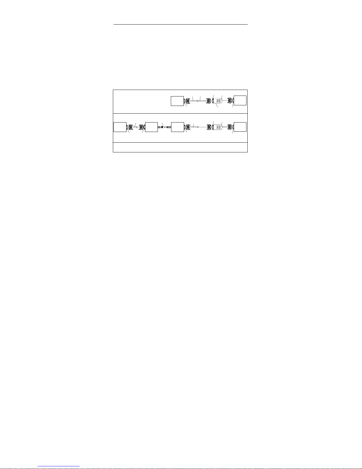
With ’direct connection’, the TS adapter allows you to link
programming devices/PCs with S7/M7/C7 systems. With this
setup, the TS adapter corresponds in functionality to the PC
adapter.
With ’modem connection’, the TS adapter enables you to link
programming devices/PCs with S7/M7/C7 systems over the
telephone network.
PC
19.2/38.4 kb
RS232
COM1...
S7/M7/C7
system
MPI/DP
TS adapterRS232
Switch
19.2/38.4 kbps
1) RS232 cable 6ES7 901-1BF00-0XA0, length 6m
1)
Direct Connection
2) Modem cable (supplied with modem)
Modem
PG/PC
RS232
RS232
COM1...
RS232
Modem
Telephone network
MPI/DP
TS adapterRS232
2)
2)
Modem Connection
S7/M7/C7
system
Figure 1-2 TS Adapter in the System
The TeleService optional package is always required to
operate the TS adapter (see 5.2 Software). The switch on the
adapter is used to change the transmission rate on the
RS232 side in direct connection. With modem connection, it
has no function.
Page 7

PC/TS AdapterQuick Reference Guide
PC/TS Adapter
A5E00078070-02
3
MPI/DP connector
Adapter
RS232 connector
LED “POWER”
LED “ACTIVE”
Switch
“19.2/38.4 kbps”
Figure 1-3 Adapter
The two adapter types differ with respect to the location of the
MPI/DP parameters:
S The MPI/DP parameters for the PC adapter are set in
“Set PG/PC interface”. When opening an online display
for the first time, ther parameters are transferred to the PC
adapter.
S The MPI/DP parameters for the TS adapter are set via a
Teleservice application and stored permanently on the TS
adapter. When opening an online display for the first time,
these parameters are activated.
Page 8

PC/TS Adapter Quick Reference Guide
4
PC/TS Adapter
A5E00078070-02
2 Package Components
S Adapter
S Quick Reference Guide
S Mounting assembly (TS adapter only)
3 Accessories (not part of the adapter package)
S RS232 cable, 6 meters in length 6ES7 901-1BF00-0XA0
(required to operate the PC adapter and to operate the
TS adapter in direct connection only).
4 MPI/DP Network
A maximum of 32 nodes can be interfaced to an MPI/DP
network segment. The total cable length may not exceed 50
meters. Using so-called RS485 repeaters, several network
segments can be combined to form a network comprising a
maximum of 127 nodes.
The data signalling rate in an MPI/DP network is max. 12
Mbit/s.
Der Adapter unterstützt Übertragungsraten bis max.
1,5 Mbit/ s.
Note
Also refer to “S7-300, Hardware and Installation”.
!
Warning
If the transmission rate is 187.5 Kbits/sec and
higher, it i s n o t allowed to insert cable extensions
in the S7/M7/C7 adapter system connection
(spur lines not allowed).
Page 9
PC/TS AdapterQuick Reference Guide
PC/TS Adapter
A5E00078070-02
5
5 Prerequisites for Operation
5.1 Hardware
PC/programming device with a free COM port (COM1 or
COM2, 9-pin COM connection). Appropriate adapters for
other connector combinations are available in specialist
shops, for example 9-pin to 25-pin subminiature D connector.
GND
DCD
RXD
TXD
DTR
DSR
RTS
CTS
RI
Shield
Shield
Shield
Shield
25-pin subminiature D:
Connector casingConnector casing
Signal:
9-pin subminiature D:
8
3
2
20
7
6
4
5
22
1)
1)
Pins or sockets, depending on usage
1
2
3
4
5
6
7
8
9
1)
Figure 1-4 9-Pin - 25-Pin RS232 Adapter
5.2 Software
PC adapter
S STEP 7 Standard Package from V1 or
S S7 DOS
TS adapter
S STEP 7 Standard Package from V3.1 and
S TeleService optional package from Version 3.0
Page 10

PC/TS Adapter Quick Reference Guide
6
PC/TS Adapter
A5E00078070-02
6 Connecting the Adapter
6.1 Safety-related Guidelines
Qualified Personnel
A device/system may only be commissioned or operated by
qualified personnel. Qualified personnel as referred to in
safety guidelines in this document are persons authorized to
energize, de-energize, clear, ground, and tag circuits,
equipment and systems in accordance with established
safety practice. For a detailed description of the
safety-related guidelines, please refer to the Appendix.
Proper Usage
Please observe the following:
!
Warning
The equipment/system or the system
components may only be used for the
applications described in the catalog or the
technical description, and only in combination
with the equipment, components, and devices of
other manufacturers as far as this is
recommended or permitted by Siemens.
The product will function correctly and safely only
it it is transported, stored, set up, and installed as
intended, and operated and maintained with
care.
Cleaning the Device
The device may be cleaned only using a soft cotton cloth and
neutral detergent. Make sure that no liquid penetrates the
housing.
Page 11
PC/TS AdapterQuick Reference Guide
PC/TS Adapter
A5E00078070-02
7
6.2 General Remarks
MPI/DP side:
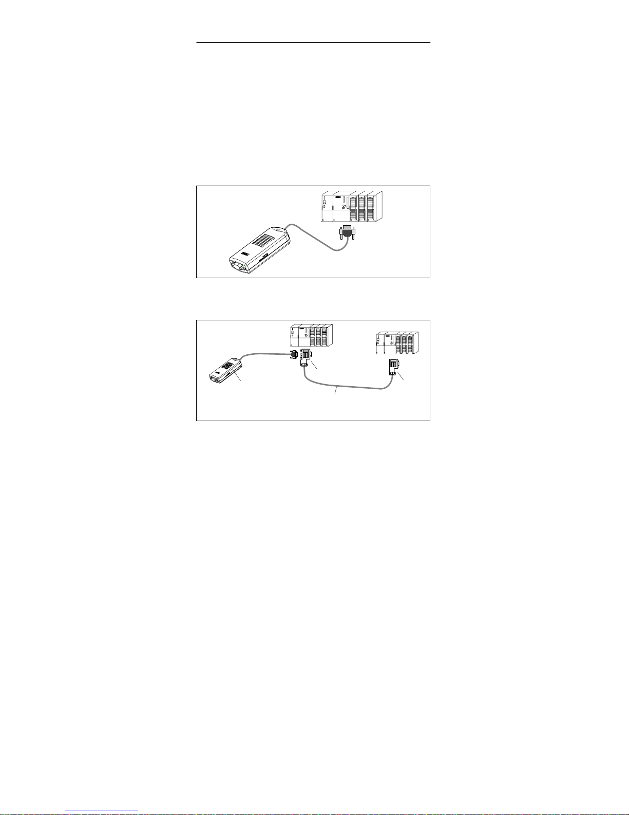
Adapter and S7/M7/C7 system each represent one network
node. In networks comprising two nodes (adapter and
S7/M7/C7 system), the adapter is plugged directly into the
S7/M7/C7 system’s MPI/DP port; in networks consisting of
more than two nodes, the adapter is plugged into a Profibus
connector’s “PG port” (SINEC L2 bus connector); for details,
please refer to catalog IK10.
S7
Figure 1-5 Connecting to an S7 System
(Two Network Nodes)
S7x
S7y
PROFIBUS bus cable
Adapter
4)
3)
4)
Profibus connector
3)
Bus connector with PG port
Figure 1-6 Connecting to Networked S7 Systems
(MPI/DP Network , Two or More Network
Nodes)
Page 12
PC/TS Adapter Quick Reference Guide
8
PC/TS Adapter
A5E00078070-02
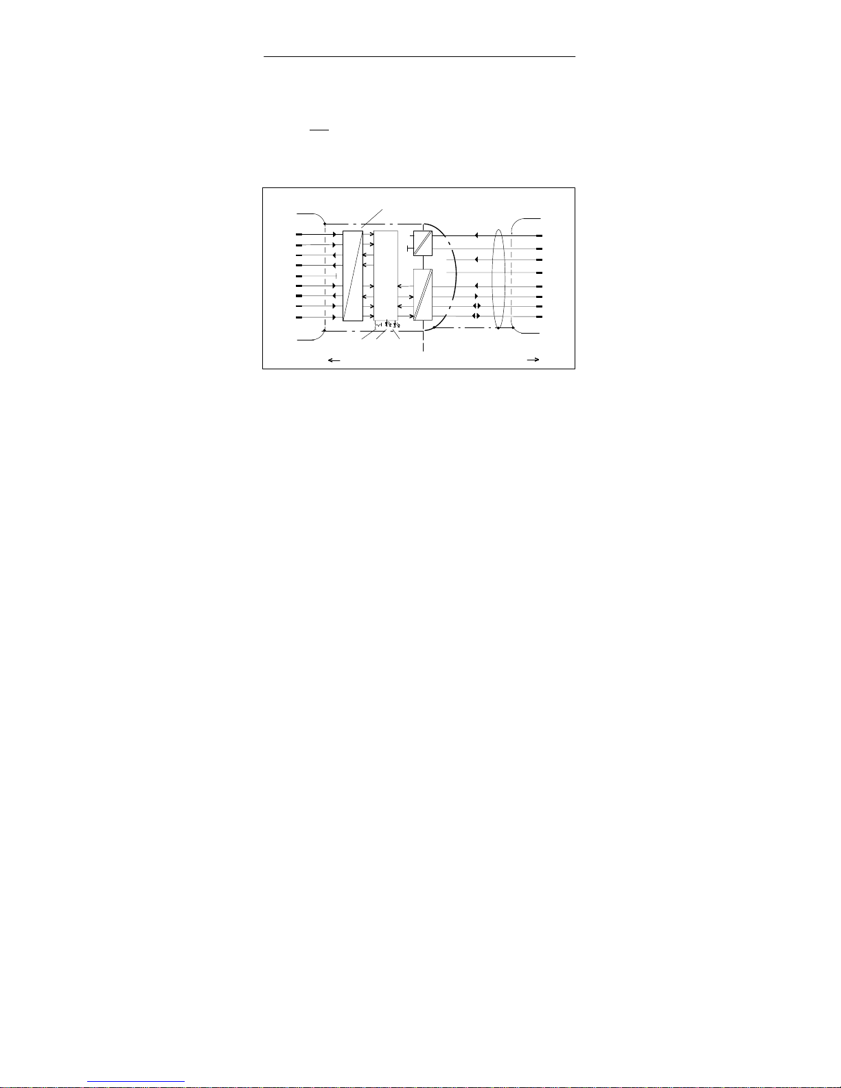
As the adapter receives its power supply via the MPI/DP interface, only those interfaces can be used which provide
24 V DC and
5 V DC with the voltages and currents specified
in the table in the ”Technical Specifications” (Chapter 7). Therefore a connection at the free end of a PROFIBUS cable is
not possible.
7
4
9
8
3
9-pin subminiature D:
1
2
3
4
5
6
7
8
9
GND
DCD
RXD
TXD
DTR
DSR
RTS
CTS
RI
P24V
M24V
P5V
M5V
RTSAS
RTS_PG
LTG_A
LTG_B
9-pin subminiature D:
CMOS
RS232
Adapter
+5V
50mA (typ)
40mA (typ)
PC potential area S7/M7/C7 potential area
RS232 Interface
19.2/38.4 kbps
Electronics
S1 ACTIVE POWER
2
6
MPI/DP Interface
9.6 to 1500 Kbps
5
Figure 1-7 Block Diagram of the Adapter
The adapter provides electrical isolation between its MPI/DP
interface and RS232 interface within a safety extra-low
voltage (SEL V) circuit, thus allowing direct operation even on
ungrounded S7/M7/C7 systems.
RS232 side:
S See Figures 1-1/1-2 “PC/TS Adapter in the System” for
direct connection details. An RS232 cable is required to
connect a PC/programming device to the adapter’s
RS232 interface (COM2-PC-compatible). This cable must
be ordered separately (see 3. “Accessories”).
Page 13
PC/TS AdapterQuick Reference Guide
PC/TS Adapter
A5E00078070-02
9
1
2
3
4
5
6
7
8
9
Shield
Shield Shield
Shield
9-pin subminiature D:
NC
Connector casing
NC
NC NC
Connector casing
1
2
3
4
5
6
7
8
9
Signal:
GND
DCD
RXD
TXD
DTR
DSR
RTS
CTS
RI
DCD
RXD
TXD
DTR
DSR
RTS
CTS
RI
GND
Signal:
9-pin subminiature D:
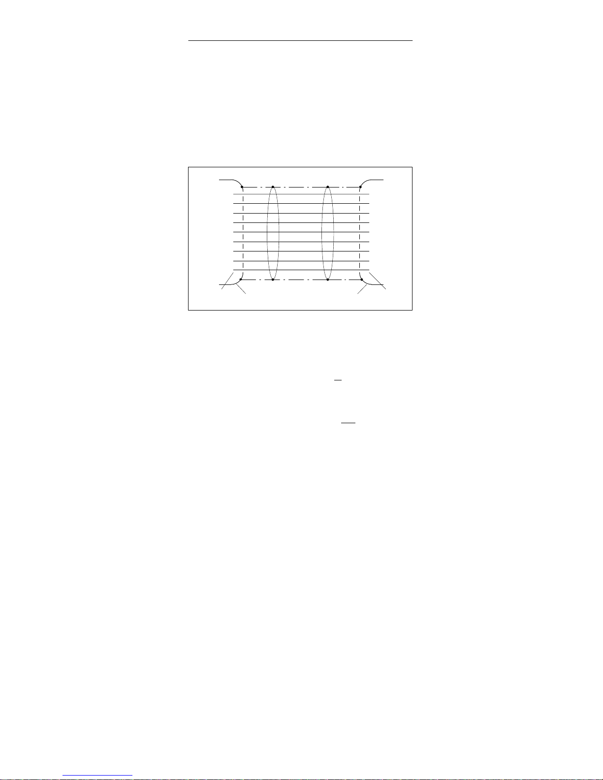
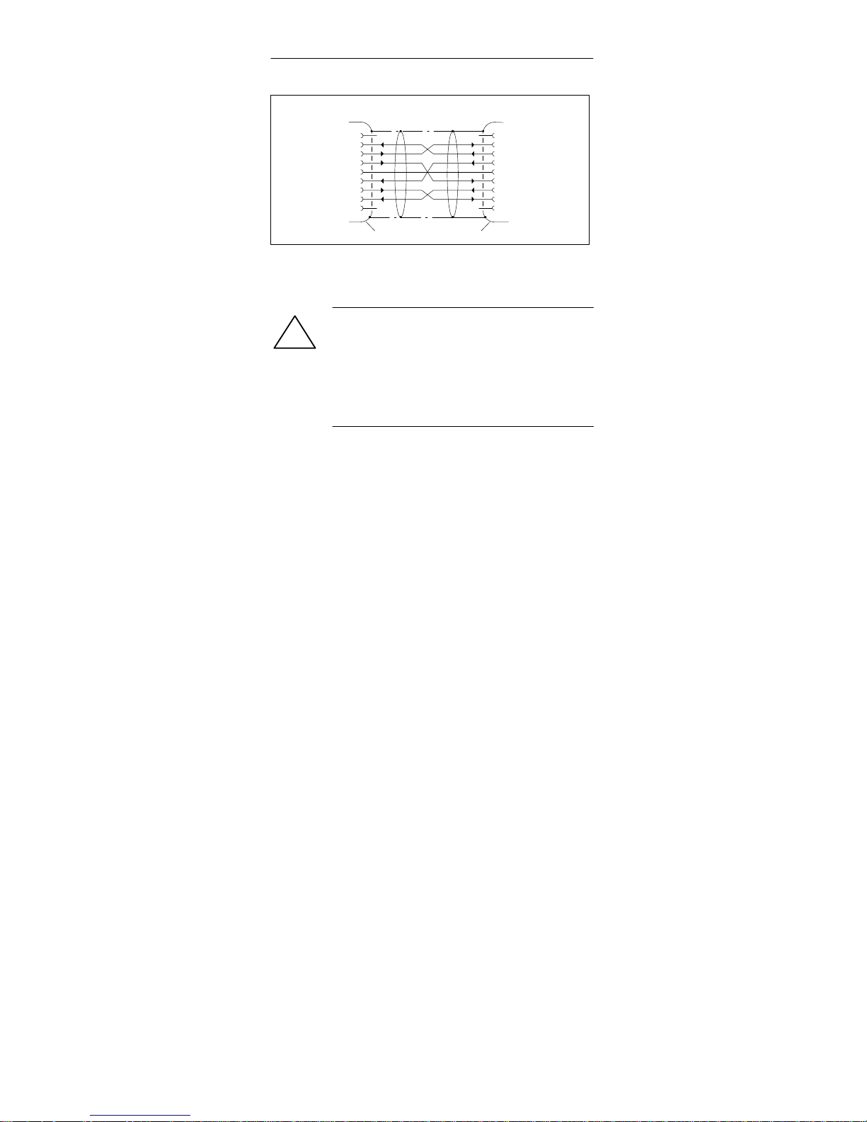
Figure 1-8 RS232 Cable 6ES7 901-1BF00-0XA0
!
Warning
The RS232 cable listed under Point 3
(Accessories) ensures that EMC requirements
are met.
This cannot be guaranteed if you use a different
cable and you do so at your own risk.
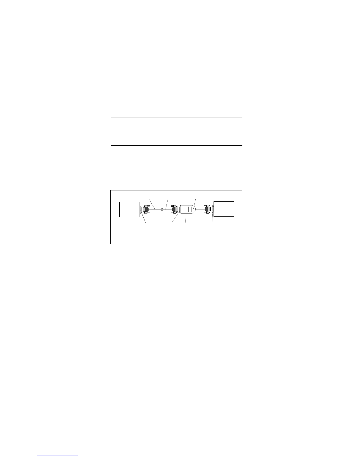
S See Figure 1-2 “TS Adapter in the System” for details of
modem connection. A modem is connected to the RS232
interface of the TS adapter using the enclosed RS232
cable. In the modem description, this cable is used for
connecting the modem to a PC. If this modem cable does
not have a 9-pin SUB-D socket connector on the TS
adapter side, the relevant adapter must be used
(Figure 1-5).
Page 14
PC/TS Adapter Quick Reference Guide
10
PC/TS Adapter
A5E00078070-02
6.3 Pin Configuration
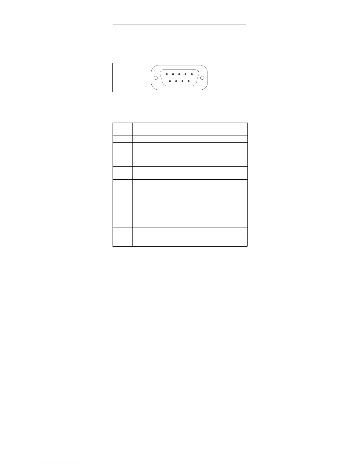
The MPI/DP connector has the following pin configuration:
5
1
9
6
Figure 1-9 MPI/DP Connector
Signals
Pin
No.
Abbreviation
Description Input/
Output
1 NC Pin is unassigned 2 M24V 24 V supply’s 0 V line, sup-
plies adapter electronics via
DC/DC converter (PC
potential area)
Input
3 LTG_B Data line B Input/out-
put
4 RTSAS RTSAS Control signal for
receive data current; the
signal is active ‘1’ when the
directly connected interface
module is transmitting.
Input
5 M5V 5 V supply’s 0 V line,
supplies the adapter’s
S7/M7/C7 potential area
Input
6 P5V 5 V supply’s +5V line,
supplies the adapter’s
S7/M7/C7 potential area
Input
Page 15

PC/TS AdapterQuick Reference Guide
PC/TS Adapter
A5E00078070-02
11
Pin
No.
Input/
Output
DescriptionAbbre-
viation
7 P24V 24V supply’s +24V line,
supplies adapter electronics
via DC/DC converter (PC
potential area)
Input
8 LTG_A Data line A Input/out-
put
9 RTS_PGAdapter’s RTS output
signal. The signal is ‘1’
when the adapter is
transmitting.
Output
Shield On connector casing*
* The shield is interconnected with the RS232 connector via
the adapte casing’s shield.
Page 16
PC/TS Adapter Quick Reference Guide
12
PC/TS Adapter
A5E00078070-02
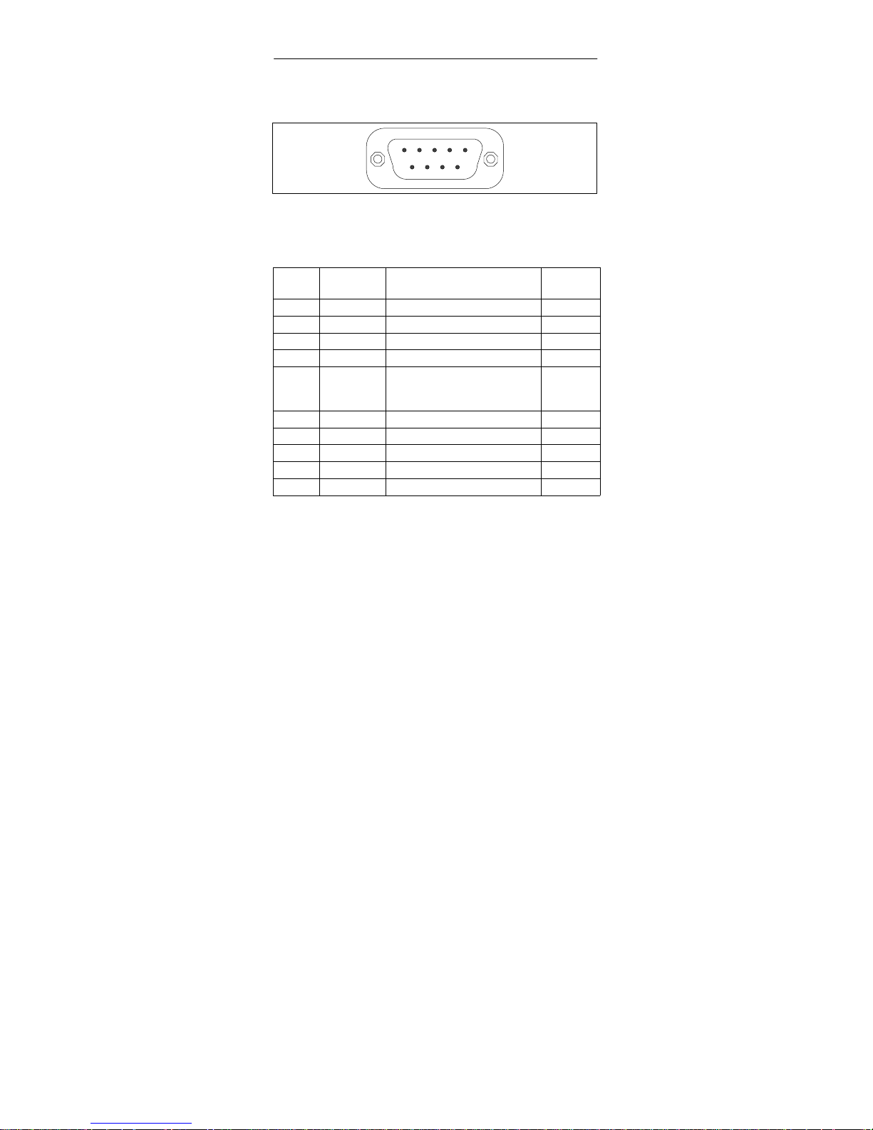
The RS232 connector has the following pin assignments:
5
1
9
6
Figure 1-10 RS232 Connector (PC-compatible)
Signals
Pin
No.
Abbreviation
Description Input/
Output
1 DCD Data Carrier Detect Input
2 RXD Received Data Input
3 TXD Transmitted Data Output
4 DTR Data Terminal Ready Output
5 GND Reference potential (0V)
for all RS232 signals
(Signal Ground)
6 DSR Data Set Ready Input
7 RTS Request to Send Output
8 CTS Clear to Send Input
9 RI Ring Indicator Input
Shield On connector casing*
* The shield is interconnected with the MPI/DP connector via
the adapter casing’s shield and the MPI/DP cable shield.
Page 17
PC/TS AdapterQuick Reference Guide
PC/TS Adapter
A5E00078070-02
13
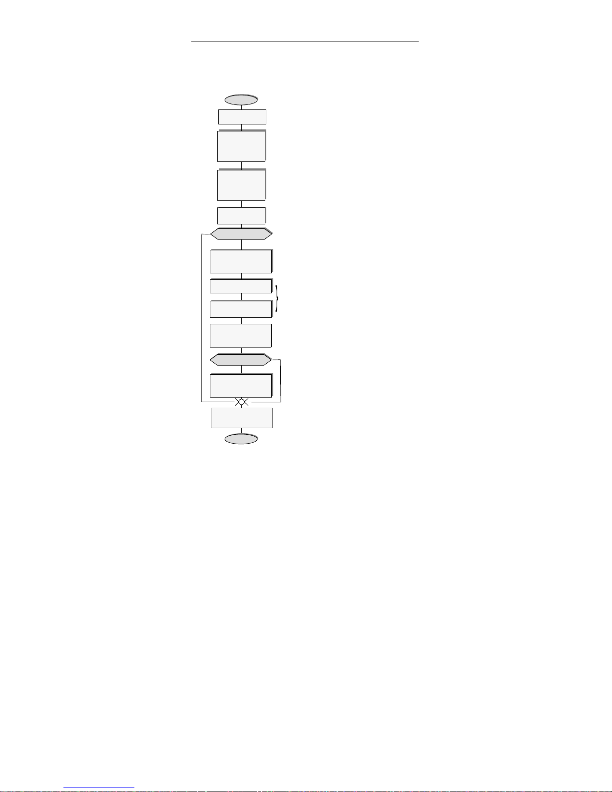
6.4 Connection Procedures
Switch PC/
modem off
Establish cable
connection on
RS232 side of
the adapter
(see 6.2 “General”, RS232 side)
Connect MPI/DP
connector of
adapter to
S7/M7/C7 system
(See 6.2 “General”, MPI/DP side)
=> Microprocessor in adapter starts
to work and switches the Power
LED to constant light after blinking
three times (see also 6.6 “Function
of the Power LED”)
Switch PC/
modem on
1st startup?
Start
N
Y
Start “Set PG/PC
interface”
Adapter installieren
Can be done on installing the
STEP 7 Standard Package. If so,
check settings now.
Parameterize interface
N
Start PG/PC ->
MPI/DP network
communication
End
Close “Set PG/PC
interface”
Install adapter
TS adapter?
Check
“parameterization”
with TS application
Y
Parameterization resident in the TS adapter.
Reparameterization is possible in direct
connection and in modem connection.
LED “Active” indicates that the adapter is
active in the MPI/DP network.
Page 18
PC/TS Adapter Quick Reference Guide
14
PC/TS Adapter
A5E00078070-02
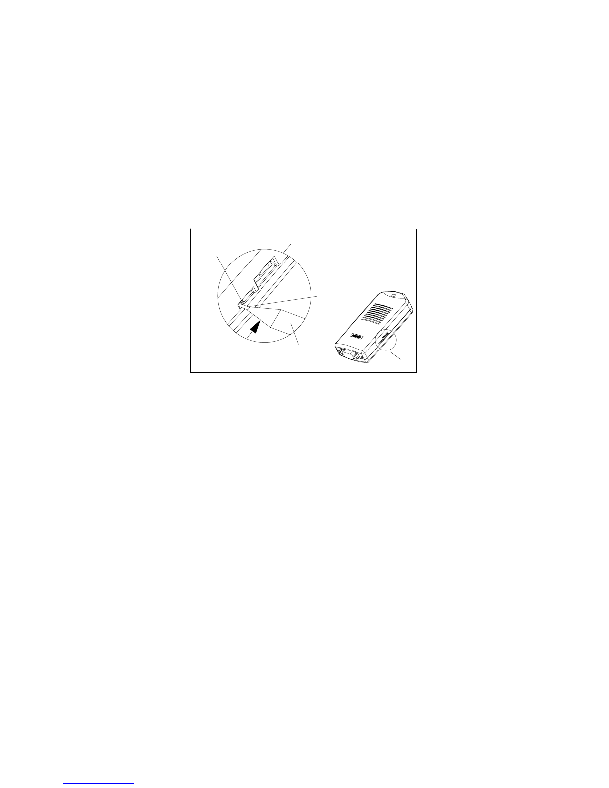
6.5 Function and Operation of the Switch
The switch is used for setting the transmission rate
(19.2 kbps or 38.4 kbps) on the RS232 side of the adapter
variant in direct connection. It has no function with modem
connection.
The transmission rate set with the switch must agree with the
rate parameterized for the PC in “Set PG/PC interface”.
Note
A Transmission speed of 38,4 kbit/s is only possible using
STEP 7 Version 3.1 or higher.
Operating the switch:
Ball-point pen
Operating
lever
Direction
of slide
∅ max. 1.7
mm
Cutout X
X
Figure 1-1 1 Location of the Switch
Note
Operating the switch resets the software parameterization of
the adapter.
Page 19
PC/TS AdapterQuick Reference Guide
PC/TS Adapter
A5E00078070-02
15
The switch is operated only infrequently and is recessed so
that it cannot be operated inadvertently . See Figure 1-11 for
the location of the switch. Both switch positions are labeled
on the underside of the unit.
To operate the switch, please use a ball-point pen
(“retractable ball-point”) up to a diameter of 1.7 mm or a blunt
instrument of the same size. Insert the extended point
between the operating lever and the housing cutout on the
side with the operating lever, and slide the operating lever
into the opposite position (see Figure 1-1 1).
!
Warning
Pointed objects (for example, needles) or
breakable objects (for example, pencils) must not
be used for operating the switch.
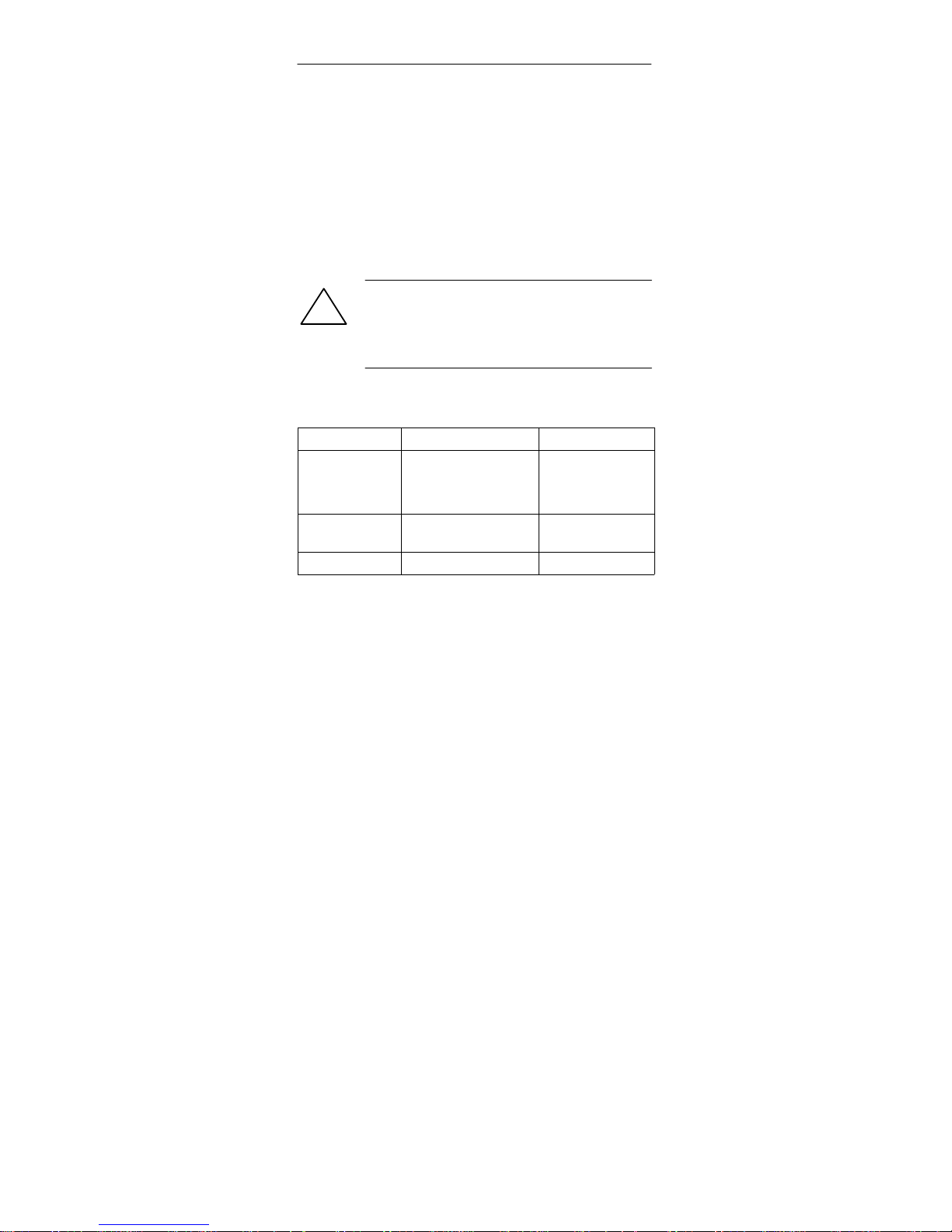
6.6 Function of the Power LED
LED Meaning Response
Off S 24 V DC supply
voltage missing
S Fatal hardware fault
Check voltage
supply
Replace adapter
Constant
blinking
Hardware fault
detected per software
Replace adapter
On Ready for use*
* After switching on, a few seconds will elapse before the
LED lights up.
6.7 Function of the active LED
The active LED shows that the adapter on the MII/DP bus is
transmitting.
Page 20
PC/TS Adapter Quick Reference Guide
16
PC/TS Adapter
A5E00078070-02
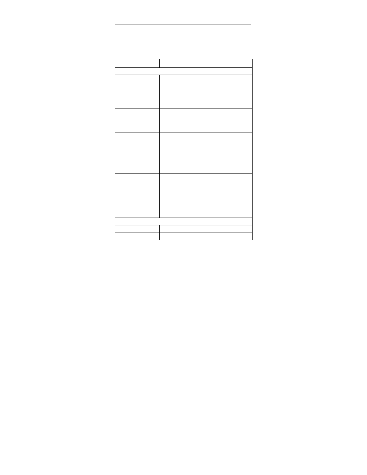
7 Technical Specifications
All required specifications are listed in the table below.
Designation Technical Specifications
PC adapter
Order number PC Adapter 6ES7 972-0CA2x-0XA0
TS Adapter 6ES7 972-0CA3x-0XA0
Dimensions 108 mm x 50 mm x 24 mm (4.25 in. x 1.96 in.
x 0.94 in.) (L x W x H)
Weight Approx. 0.15 kilograms
Interfaces
to S7/M7/C7
to PC
RS485 (bis max. 1,5 Mbit/s)
RS232 (19.2 kbps / 38.4 kbps/can be set
with switch)
Supply voltage (VN) VN1 = 24 VDC (17 VDC to 30 VDC)
VN2 = 5 VDC (4.8 VDC to 5.25 VDC)
V1 and V2 are taken from the MPI/DP
interface of the S7/M7/C7 system.
Both voltage sources must be limited to a
nominal current of 3 A by means of
overcurrent limiting or fuses.
Power input (IN) I1= 50 mA (typ.)/90 mA (max.)
I2= 40 mA (typ.)/70 mA (max.)
Two network nodes, terminators inoperative,
no fuses in adapter.
Inrush current I1 max. 0.5 A; 14 ms
I2 max. 0.2 A; 1.5 ms
Type of protection IP20
Safety
VDE specification VDE 0805 5 EN 60950 5 IEC 950
Noise emisson <45dB(A) to DIN 45635 (no fan)
Page 21

PC/TS AdapterQuick Reference Guide
PC/TS Adapter
A5E00078070-02
17
Designation Technical Specifications
Electromagnetic compatibility (EMC)
Emitted interference
Limit class B to EN 55022 = CISPR 22
Interference
immunity on signal
lines
"2kV (to IEC 801-4/
IEC 1000-4-4; Burst)
Interference
immunity against
discharging of static
electricity
"6kV Contact discharge
(to IEC 801-2/IEC 1000-4-2;
ESD)
"8kV Air discharge (to IEC 801-2/IEC
1000-4-2; ESD)
Highfrequency
radiation
10 V with 80% amplitude modulation at
1 kHz, 10 kHz - 80 MHz (to ENV 50141)
10 V/m with 80% amplitude modulation at 1
kHz, 80 Mhz - 1GHz (to ENV 50140)
10 V/m pulse-modulated 50% load factor at
900 MHz (to ENV 50204)
Climatic conditions
Temperature
operation
storage/
shipping
Tested to DIN IEC 68-2-1, DIN IEC 68-2-2
"0°C to +60°C
(rate of temperature change
max. 10 °C/h)
-40°C to +70°C
(rate of temperature change
max. 20°C/h)
Relative humidity
operation
storage/
shipping
Tested to DIN IEC 68-2-3
5% to 85% at 30°C (no condensation)
5% to 93% at 40°C (no condensation)
Page 22
PC/TS Adapter Quick Reference Guide
18
PC/TS Adapter
A5E00078070-02
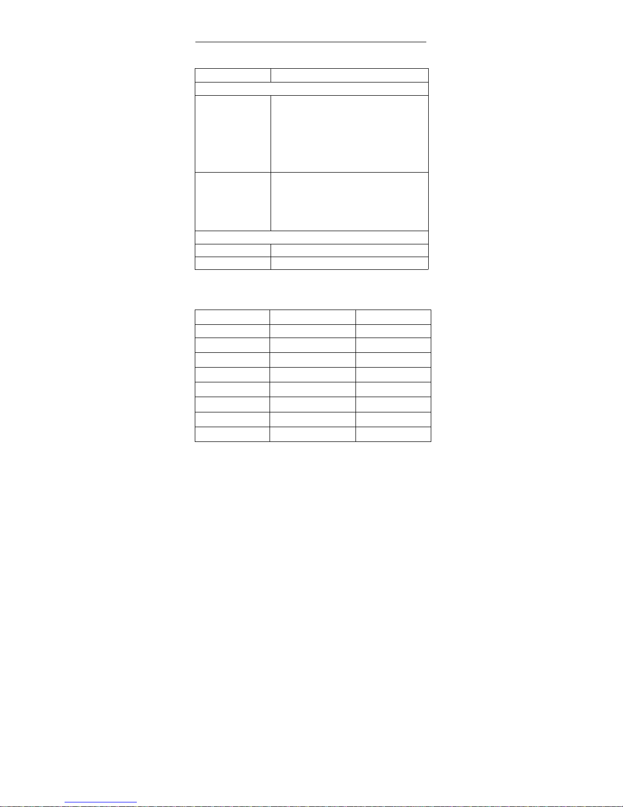
Designation Technical Specifications
Mechanical environmental conditions
Vibration
Operation
shipping
(adapter
packed
for
transport)
Tested to DIN IEC 68-2-6
10 to 58 Hz, amplitude 0.075 mm
58 to 150 Hz acceleration 9.8 m/s
2
5 - 9 Hz, amplitude 3.5 mm
9 - 500 Hz, acceleration 9.8 m/s
2
Shock
operation
shipping
(adapter
packed for
transport)
Tested to DIN IEC 68-2-27/29
Half sine: 100 m/s
2
(10 g), 16 ms
Half sine: 250 m/s
2
(25 g), 6 ms
Special features
Quality assurance To ISO 9001
Maintenance Maintenance free (no battery)
7.1 Supplied PC/TS Adapter Versions
Product MLFB Version
PC Adapter 6ES7972-0CA20-0XA0 V3.0
6ES7972-0CA21-0XA0 V3.1
6ES7972-0CA22-0XA0 V5.0
6ES7972-0CA23-0XA0 V5.1
TS Adapter 6ES7972-0CA30-0XA0 V3.0
6ES7972-0CA32-0XA0 V5.0
6ES7972-0CA33-0XA0 V5.1
6ES7972-0CA34-0XA0 V5.2
Page 23

PC/TS AdapterQuick Reference Guide
PC/TS Adapter
A5E00078070-02
19
7.2 Features of the PC/TS Adapter Versions
PC Adapter V3.0 V3.1 V5.0 V5.1
Transmission speed
to PC
19.2 Kbps 19.2 Kbps
and
38.4 Kbps
19.2 Kbps
and
38.4 Kbps
19.2 Kbps
and
38.4 Kbps
Transmission speed
of MPI/DP network
187.5 Kbps 187.5 Kbps 9.6 Kbps
to
1.5 Mbps
9.6 Kbps
to
1.5 Mbps
DP transport
protocol
1)
– – n n
Routing support
2)
– – n n
Baud rate and profile
search
– – – n
Services with slave
initiative
– – – n
1) Enables communication with slaves on MPI/DP network
2) Allows addressing of network gateways (routers) and enables communication
beyond subnet limits
Page 24

PC/TS Adapter Quick Reference Guide
20
PC/TS Adapter
A5E00078070-02
TS Adapter V3.0 V5.0 V5.1 V5.2
Transmission
speed to PC
19.2 Kbps 19.2 Kbps
and
38.4 Kbps
19.2 Kbps
and
38.4 Kbps
19.2 Kbps
and
38.4 Kbps
Transmission
speed of
Adapter-Modem
interface
2.4 Kbps
4.8 Kbps
9.6 Kbps
19.2 Kbps
38.4 Kbps
2.4 Kbps
4.8 Kbps
9.6 Kbps
19.2 Kbps
38.4 Kbps
57.6 Kbps
115.2 Kbps
2.4 Kbps
4.8 Kbps
9.6 Kbps
19.2 Kbps
38.4 Kbps
57.6 Kbps
115.2 Kbps
2.4 Kbps
4.8 Kbps
9.6 Kbps
19.2 Kbps
38.4 Kbps
57.6 Kbps
115.2 Kbps
Transmission
speed of MPI/DP
network
187.5 Kbps 9.6 Kbps
to
1.5 Mbps
9.6 Kbps
to
1.5 Mbps
9.6 Kbps
to
1.5 Mbps
DP transport
protocol
1)
– n n n
Routing support
2)
– n n n
Call from PLC
with “PG_DIAL”
FB
– n n n
Access
protection
– n n n
Baud rate and
profile search
– – n n
Services with
slave initiative
– – n n
PLC – PLC
coupling with
”AS_DIAL” FB
– – n n
Sending an SMS
with FB
“SMS_SEND”
– – – n
1) Enables communication with slaves on MPI/DP network
2) Allows addressing of network gateways (routers) and enables communication
beyond subnet limits
Page 25
PC/TS AdapterQuick Reference Guide
PC/TS Adapter
A5E00078070-02
21
8 Approvals
8.1 Approval for USA and Canada
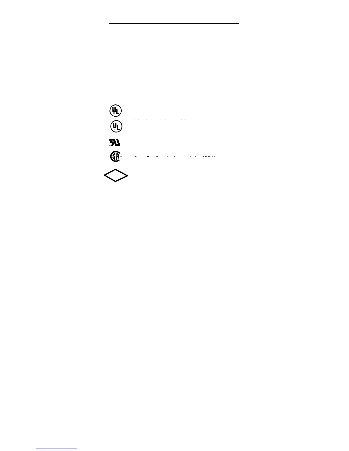
UL/CSA approval
Important for the U.S.A. and Canada:
The characters stamped on a device are
indicative of the requirements which that device
meets:
Underwriters Laboratories (UL) to the UL 1950
standard, Report E1 1 5352
standard, Report E1 1 5352
Underwriters Laboratories (UL) to the Canadian
standard C22.2 No. 950
UL recognition mark
Canadian Standard Association (CSA) to
standard C22.2 No. 950 or C22.2 No. 220,
Report LR 81690
FM approval to Factory Mutual Approval
Standard 3611.
C
FM
APPROVED
Page 26

PC/TS Adapter Quick Reference Guide
22
PC/TS Adapter
A5E00078070-02
FM Approval
FM approval to Factory Mutual Approval Standard 361 1.
!
Warning
Personal injury or property damage can result.
In hazardous areas, personal injury or property
damage can result if you close or disconnect an
electrical circuit during operation (e.g. plug-in
connections, fuses, switches).
Do not close or disconnect any live circuits
unless explosion hazards can be definitely
excluded.
!
Warning
WARNING - DO NOT DISCONNECT WHILE
CIRCUIT IS LIVE
UNLESS LOCATION IS KNOWN TO BE
NON-HAZARDOUS
Page 27
PC/TS AdapterQuick Reference Guide
PC/TS Adapter
A5E00078070-02
23
8.2 Approvals for Europe
EMC Guidelines
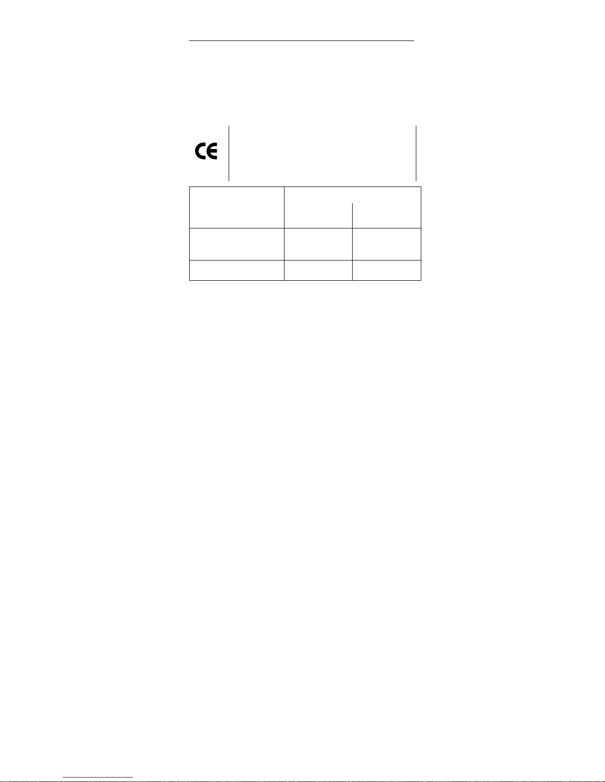
The following applies for the SIMATIC product described in
this manual:
The device meets the requirements of EU
Directive 89/336/EEC “Electromagnetic
Compatibility” and has been designed for the
following areas of application as per the CE
marking:
Area of Application
Requirements:
Emitted
interference
Noise immunity
Domestic, business and
commercial,
including small businesses
EN 50081-1: 1992 EN 50082-1: 1992
Industrial EN 50081-2: 1993 EN 50082-2: 1995
Declarations of Conformity
In accordance with the above-mentioned EU Directive, Article
10 (2), the EU declarations of conformity and the associated
documentation are held at the disposal of the competent
authorities at the address below:
Siemens Aktiengesellschaft
Bereich Automation and Drives
A&D AS RD 4
Postfach 1963
D-92209 Amberg
Observing the Installation Guidelines
Care must be taken both at startup and during operation that
the installation guidelines and safety information provided in
2the documentation be carefully observed.
Page 28

PC/TS Adapter Quick Reference Guide
24
PC/TS Adapter
A5E00078070-02
 Loading...