

Page 1
SIMATIC Industrial PC SIMATIC Panel PC 577
DOCUMENTATION
Operating Instructions Edition 04/2006
Industrial PC
Panel PC 577
simatic
DOCUMENTATION
Page 2

Page 3

SIMATIC
Industrial PC
SIMATIC Panel PC 577
Operating Instructions
Preface
Safety instructions and
general notes
Description
Planning use
Installation
Connecting
Commissioning
1
2
3
4
5
6
Operation and configuration
Operating
Integration in TIA
Servicing and maintenance
Alarm, error and system
messages
Troubleshooting and FAQs
Technical specifications
7
8
9
10
11
12
13
Release 04/2006
A5E00798484-01
Detailed descriptions
Appendix
14
A
Page 4
Safety Guidelines
This manual contains notices you have to observe in order to ensure your personal safety, as well as to prevent
damage to property. The notices referring to your personal safety are highlighted in the manual by a safety alert
symbol, notices referring only to property damage have no safety alert symbol. These notices shown below are
graded according to the degree of danger.
Danger
indicates that death or severe personal injury will result if proper precautions are not taken.
Warning
indicates that death or severe personal injury may result if proper precautions are not taken.
Caution
with a safety alert symbol, indicates that minor personal injury can result if proper precautions are not taken.
Caution
without a safety alert symbol, indicates that property damage can result if proper precautions are not taken.
Notice
indicates that an unintended result or situation can occur if the corresponding information is not taken into
account.
If more than one degree of danger is present, the warning notice representing the highest degree of danger will
be used. A notice warning of injury to persons with a safety alert symbol may also include a warning relating to
property damage.
Qualified Personnel
The device/system may only be set up and used in conjunction with this documentation. Commissioning and
operation of a device/system may only be performed by qualified personnel. Within the context of the safety notes
in this documentation qualified persons are defined as persons who are authorized to commission, ground and
label devices, systems and circuits in accordance with established safety practices and standards.
Prescribed Usage
Note the following:
Warning
This device may only be used for the applications described in the catalog or the technical description and only in
connection with devices or components from other manufacturers which have been approved or recommended by
Siemens. Correct, reliable operation of the product requires proper transport, storage, positioning and assembly
as well as careful operation and maintenance.
Trademarks
All names identified by ® are registered trademarks of the Siemens AG. The remaining trademarks in this
publication may be trademarks whose use by third parties for their own purposes could violate the rights of the
owner.
Disclaimer of Liability
We have reviewed the contents of this publication to ensure consistency with the hardware and software
described. Since variance cannot be precluded entirely, we cannot guarantee full consistency. However, the
information in this publication is reviewed regularly and any necessary corrections are included in subsequent
editions.
Siemens AG
Automation and Drives
Postfach 48 48
90437 NÜRNBERG
GERMANY
Order No.: A5E00798484-01
Edition 04/2006
Copyright © Siemens AG
200420052006.
Technical data subject to change
Page 5

Preface
This manual
Purpose of the manual
This manual provides information based on the requirements defined by DIN 8418 regarding
mechanical engineering documentation. This information relates to the device, its place of
use, transport, storage, installation, use and maintenance.
This manual is intended for the following target groups:
• Users
• Commissioning engineers
• Service technicians
• Maintenance technicians
Please read the section "Safety instructions and general notes" carefully.
Knowledge required
A solid background in personal computers and Microsoft operating systems is required to
understand this manual. General knowledge in the field of automation control engineering is
recommended.
Scope of this manual
This manual applies to devices with the order numbers 6AV782.…
SIMATIC Panel PC 577
Operating Instructions, Release 04/2006, A5E00798484-01
iii
Page 6

Preface
Related documentation
The documentation for the Panel PC includes the following sections:
• SIMATIC Panel PC 577, Operating Instructions (compact) with the following information:
– Commissioning
– Legal information
• SIMATIC Panel PC 577, Operating Instructions
The documentation is supplied with the Panel PC in electronic form as a PDF file on the
"Documentation & Drivers" CD. QuickStart for the Panel PC 577 is also supplied in printed
form. The documentation is available in German, English, French, Italian and Spanish.
Additional information about the Windows operating system is available in the Internet at the
Microsoft homepage, "www.Microsoft.com
Online Availability
The following links will bring you directly to the technical documentation collection for
SIMATIC products and systems in the languages German, English, French, Italian and
Spanish.
• SIMATIC Guide Technische Dokumentation in Deutsch:
http://www.ad.siemens.de/simatic/portal/html_00/techdoku.htm
".
Conventions
• SIMATIC guide to technical documentation in English:
http://www.ad.siemens.de/simatic/portal/html_76/techdoku.htm
The following text notation will facilitate reading this manual:
Representation Scope
"File"
"File > Edit" Operational sequences, e.g., menu items/shortcut menu items.
<F1>, <Shift>+<F1> Keys and key combinations
• Terminology that occurs in the user interface, e.g., dialog
names, tabs, buttons, menu commands.
• Inputs required, e.g., limit values, tag values
• Path information
The term "Panel PC 577", "control unit" and "computer unit" is uniformly refered to as the
"device" in these operating instructions. The full term is only used when a concrete reference
is necessary.
Note
A note is important information about the product, handling the product or a reference to
specific sections of the documentation that require special consideration.
SIMATIC Panel PC 577
iv Operating Instructions, Release 04/2006, A5E00798484-01
Page 7

Preface
Trademarks
All names labeled with ® symbol are registered trademarks of Siemens AG. Other names
used in this documentation may be trademarks, the use of which by third parties for their
own purposes could violate the rights of the owner.
HMI®
SIMATIC®
SIMATIC HMI®
SIMATIC ProTool®
SIMATIC WinCC®
SIMATIC WinCC flexible®
Panel PC 577®
Panel PC 677®
Panel PC 877®
Additional support
Representatives and offices
If you have questions concerning the use of the described product which are not answered in
this manual, please contact the Siemens representative in your area.
Find your contact partner at:
http://www.siemens.com/automation/partner
A guide to the technical documentation for the various SIMATIC products and systems is
available at:
http://www.siemens.com/simatic-tech-doku-portal
The online catalog and the online ordering system is available at:
http://mall.automation.siemens.com
Training center
To familiarize you with automation systems, we offer a variety of courses. Please contact
your regional training center or the central training center in D-90327 Nuremberg, Germany.
Phone: +49 (911) 895-3200
Internet: http://www.sitrain.com
SIMATIC Panel PC 577
Operating Instructions, Release 04/2006, A5E00798484-01
v
Page 8

Preface
Technical support
You can reach the technical support for all A&D products
via the support request form on the web:
• http://www.siemens.com/automation/support-request
• Phone: + 49 180 5050 222
• Fax: + 49 180 5050 223
Additional information about our technical support is available in the Internet at:
http://www.siemens.com/automation/service
Service & support on the Internet
In addition to our documentation, we offer our complete knowledge base on the Internet at.
http://www.siemens.com/automation/service&support
There you will find:
• The newsletter which provides the latest information on your products.
• Relevant documentation for your application, which you can access via the search
function in our service & support database.
• A forum where users and experts from all over ther world exchange ideas.
• You local Automation & Drives representative.
• Information about on-site service, repairs, spare parts. And lots more under "Services".
SIMATIC Panel PC 577
vi Operating Instructions, Release 04/2006, A5E00798484-01
Page 9

Table of contents
Preface ...................................................................................................................................................... iii
1 Safety instructions and general notes..................................................................................................... 1-1
1.1 Safety instructions...................................................................................................................... 1-1
1.2 General information, download "Panel PC" ............................................................................... 1-5
2 Description.............................................................................................................................................. 2-1
2.1 Application features ................................................................................................................... 2-1
2.2 Design ........................................................................................................................................ 2-2
2.3 Technical features...................................................................................................................... 2-3
3 Planning use........................................................................................................................................... 3-1
3.1 Overview .................................................................................................................................... 3-1
3.2 Unpacking and checking the delivery ........................................................................................3-2
3.3 Make note of identification data ................................................................................................. 3-4
3.4 EMC directive............................................................................................................................. 3-5
3.5 Mounting positions and fastening .............................................................................................. 3-6
3.5.1 Installation instructions............................................................................................................... 3-6
3.5.2 Permitted mounting positions..................................................................................................... 3-8
3.5.3 Mounting type............................................................................................................................. 3-8
3.5.4 Degree of protection .................................................................................................................. 3-9
3.6 Mounting cut-out ...................................................................................................................... 3-10
3.6.1 Selecting and creating the mounting cut-out ........................................................................... 3-10
3.6.2 Dimensions .............................................................................................................................. 3-11
4 Installation .............................................................................................................................................. 4-1
4.1 Securing with clamps ................................................................................................................. 4-1
4.2 Securing with screws ................................................................................................................. 4-2
4.3 Dimensions ................................................................................................................................ 4-4
SIMATIC Panel PC 577
Operating Instructions, Release 04/2006, A5E00798484-01
vii
Page 10

Table of contents
5 Connecting ............................................................................................................................................. 5-1
5.1 Overview .................................................................................................................................... 5-1
5.2 Interfaces.................................................................................................................................... 5-3
5.2.1 Front interfaces .......................................................................................................................... 5-3
5.2.2 Rear interfaces........................................................................................................................... 5-4
5.3 Connecting peripherals .............................................................................................................. 5-6
5.3.1 Overview .................................................................................................................................... 5-6
5.3.2 Connecting a monitor................................................................................................................. 5-6
5.3.3 USB............................................................................................................................................ 5-7
5.4 Connecting the power supply..................................................................................................... 5-9
5.5 Uninterruptible AC power supplies........................................................................................... 5-11
5.6 Connecting the equipotential bonding...................................................................................... 5-12
6 Commissioning ....................................................................................................................................... 6-1
6.1 Removing the transport lock for the hard disk ........................................................................... 6-1
6.2 Overview .................................................................................................................................... 6-3
6.3 Switching on the device. ............................................................................................................ 6-5
6.4 Setting up the Microsoft Windows operating system ................................................................. 6-7
6.5 Installing applications and drivers, Touch-Base......................................................................... 6-8
6.6 Notes about new installation of Windows 2000 ....................................................................... 6-13
7 Operation and configuration.................................................................................................................... 7-1
7.1 Normal operation........................................................................................................................ 7-1
7.1.1 Switching the device on and off ................................................................................................. 7-1
7.2 Additional drivers and applications ............................................................................................ 7-4
7.2.1 Overview .................................................................................................................................... 7-4
7.2.2 Setting the touch screen ............................................................................................................ 7-5
7.2.3 KeyTools .................................................................................................................................... 7-7
7.2.4 SystemGuard ............................................................................................................................. 7-8
7.2.5 TouchInput ................................................................................................................................. 7-9
7.2.6 CheckLanguageID ................................................................................................................... 7-10
7.2.7 Multilingual settings for the operating system.......................................................................... 7-11
8 Operating................................................................................................................................................ 8-1
8.1 Operator controls ....................................................................................................................... 8-1
8.2 Operator controls on key panels ................................................................................................ 8-3
8.2.1 Overview .................................................................................................................................... 8-3
8.2.2 Keyboard.................................................................................................................................... 8-4
8.2.3 Labeling function keys and softkeys .......................................................................................... 8-7
8.3 Operator controls of the touch screen panels............................................................................ 8-9
8.3.1 Overview .................................................................................................................................... 8-9
8.3.2 Touch screen ........................................................................................................................... 8-10
8.4 DVD-ROM drive ....................................................................................................................... 8-11
8.5 Transferring authorizations ...................................................................................................... 8-12
SIMATIC Panel PC 577
viii Operating Instructions, Release 04/2006, A5E00798484-01
Page 11

Table of contents
9 Integration in TIA .................................................................................................................................... 9-1
9.1 Industrial communications ......................................................................................................... 9-1
9.2 PROFIBUS/MPI interface and WinAC card ............................................................................... 9-2
10 Servicing and maintenance................................................................................................................... 10-1
10.1 Servicing .................................................................................................................................. 10-1
10.2 Removing and installing hardware components ...................................................................... 10-3
10.2.1 Repairs..................................................................................................................................... 10-3
10.2.2 Opening the device.................................................................................................................. 10-5
10.2.3 View of internal components with open device........................................................................ 10-9
10.2.4 Removing/installing memory modules ................................................................................... 10-10
10.2.5 PCI/WinAC cards ................................................................................................................... 10-12
10.2.5.1 Notes on the modules ............................................................................................................ 10-12
10.2.5.2 Installing expansion modules................................................................................................. 10-13
10.2.6 Drives ..................................................................................................................................... 10-17
10.2.6.1 Removing and installing a DVD-ROM drive........................................................................... 10-17
10.2.6.2 Replacing the hard disk ......................................................................................................... 10-20
10.2.7 Changing processors and heat sinks..................................................................................... 10-24
10.2.8 Replacing the back-up battery ............................................................................................... 10-26
10.2.9 Removing/installing the power supply ................................................................................... 10-28
10.2.10 Separating the control unit from the computer unit................................................................ 10-30
10.2.11 Connecting an external monitor............................................................................................. 10-37
10.3 Installing software .................................................................................................................. 10-38
10.3.1 Overview ................................................................................................................................ 10-38
10.3.2 Supplied software CDs / DVDs.............................................................................................. 10-40
10.3.3 Restoring the factory state of the software using the Restore DVD ...................................... 10-41
10.3.4 Factory state without operating system ................................................................................. 10-43
10.3.5 Installing individual drivers..................................................................................................... 10-44
10.4 Maintenance and spare parts ................................................................................................ 10-45
11 Alarm, error and system messages ............................
.......................................................................... 11-1
11.1 BIOS error messages .............................................................................................................. 11-1
11.2 Motherboard error messages................................................................................................... 11-2
12 Troubleshooting and FAQs................................................................................................................... 12-1
12.1 General problems .................................................................................................................... 12-1
12.2 Problems when using modules of third-party manufacturers .................................................. 12-3
12.3 SystemGuard errors................................................................................................................. 12-4
13 Technical specifications........................................................................................................................ 13-1
13.1 Technical data.......................................................................................................................... 13-1
13.1.1 EMC requirements ................................................................................................................... 13-1
13.1.2 General technical data ............................................................................................................. 13-2
13.1.3 Ambient and environmental conditions.................................................................................... 13-5
13.2 Dimensional drawing of the device .......................................................................................... 13-6
13.3 Keyboard table ......................................................................................................................... 13-7
SIMATIC Panel PC 577
Operating Instructions, Release 04/2006, A5E00798484-01
ix
Page 12

Table of contents
14 Detailed descriptions ............................................................................................................................ 14-1
14.1 Overview of the Panel PC 577 motherboard ........................................................................... 14-1
14.2 Riser card ................................................................................................................................. 14-2
14.3 Touch sensor ........................................................................................................................... 14-3
14.4 System resources .................................................................................................................... 14-5
14.4.1 Currently allocated system resources...................................................................................... 14-5
14.4.2 Interrupt assignment ................................................................................................................ 14-6
14.5 BIOS setup ............................................................................................................................... 14-7
14.5.1 Starting BIOS setup ................................................................................................................. 14-7
14.5.2 BIOS setup default settings...................................................................................................... 14-8
A Appendix.................................................................................................................................................A-1
A.1 Certificates and guidelines.........................................................................................................A-1
A.1.1 Guidelines and declarations.......................................................................................................A-1
A.1.2 Certificates and approvals..........................................................................................................A-3
A.1.3 ESD guideline ............................................................................................................................A-5
A.1.4 Electrostatic charging of individuals...........................................................................................A-7
A.2 Abbreviations .............................................................................................................................A-8
A.3 Glossary Definitions CU.............................................................................................................A-9
Index................................................................................................................................................ Index-1
Tables
Table 3-1 Dimensions for the mounting cut-out in mm ............................................................................ 3-12
Table 10-1 Switch settings for the various control units........................................................................... 10-36
SIMATIC Panel PC 577
x Operating Instructions, Release 04/2006, A5E00798484-01
Page 13

Safety instructions and general notes
1.1 1.1 Safety instructions
Warning
Emergencies
In the event of a device fault, remove the mains connector immediately. Inform the customer
service personnel responsible. Malfunctions can occur when the operator controls or power
cable are damaged or when liquids or foreign objects penetrate the device.
Caution
Please observe the safety instructions on the back of the cover sheet of this documentation.
You should not expand your device unless you have read the relevant safety instructions.
1
This device is compliant with the relevant safety measures to IEC, EN, VDE, UL, and CSA. If
you have questions about the validity of the installation in the planned environment, please
contact your service representative.
Repairs
Only authorized personnel are permitted to repair the device.
Warning
Unauthorized opening and improper repairs can cause considerable damage to property or
danger for the user.
SIMATIC Panel PC 577
Operating Instructions, Release 04/2006, A5E00798484-01
1-1
Page 14
Safety instructions and general notes
1.1 Safety instructions
System expansions
Only install system expansion devices designed for this device. The installation of other
expansions can damage the system and violate the radio-interference suppression
regulations. Contact your technical support team or where you purchased your PC to find out
which system expansion devices may safely be installed.
Battery
Caution
If you install or exchange system expansions and damage your device, the warranty
becomes void.
This device is equipped with a Lithium battery. Batteries may only be replaced by qualified
personnel.
Caution
There is the risk of an explosion if the battery is not replaced as directed. Replace only with
the same type or with an equivalent type recommended by the manufacturer. Dispose of
used batteries in accordance with local regulations.
Warning
Risk of explosion and release of harmful substances!
Therefore, do not throw Lithium batteries into an open fire, do not solder or open the cell
body, do not short-circuit or reverse polarity, do not heat up above 100° C, dispose of in
accordance with regulations and protect against direct exposure to sunlight, moisture and
condensation.
SIMATIC Panel PC 577
1-2 Operating Instructions, Release 04/2006, A5E00798484-01
Page 15
Safety instructions and general notes
1.1 Safety instructions
ESD guidelines
Modules containing electrostatic sensitive devices (ESDs) can be identified by the following
label:
Strictly follow the guidelines mentioned below when handling modules which are sensitive to
ESD:
• Always discharge your body´s static electricity before handling modules which are
sensitive to ESD (for example, by touching a grounded object).
• All devices and tools must be free of static charge.
• Always pull the mains connector and disconnect the battery before you install or remove
modules which are sensitive to ESD.
• Handle modules fitted with ESDs by their edges only.
• Do not touch any wiring posts or conductors on modules containing ESDs.
Warning
Following the results of a risk analysis, additional protection equipment on the machine or
the system is necessary to avoid endangering persons. With this, especially the
programming, configuration and wiring of the inserted I/O modules have to be executed, in
accordance with the safety performance (SIL, PL or Cat.) identified by the necessary risk
analysis. The intended use of the device has to be ensured.
The proper use of the device has to be verified with a function test on the system. This test
can detect programming, configuration and wiring errors. The test results have to be
documented and, if necessary, entered into the relevant documents that verify safety.
SIMATIC Panel PC 577
Operating Instructions, Release 04/2006, A5E00798484-01
1-3
Page 16

Safety instructions and general notes
1.1 Safety instructions
Electrical connection
Warning
Disconnect the device from the mains before every intervention.
Do not touch power cables or data transmission cables during electrical storms and do not
connect any cables.
High frequency radiation
Caution
Unintentional operating situations
High frequency radiation, e.g. from cell phones, can cause unintentional operating situations
under some circumstances. For more details, consult the technical data in the "EMC
requirements" chapter.
SIMATIC Panel PC 577
1-4 Operating Instructions, Release 04/2006, A5E00798484-01
Page 17

Safety instructions and general notes
1.2 General information, download "Panel PC"
1.2 1.2 General information, download "Panel PC"
Overview
Transport
Caution
The device is approved for operation in closed rooms only. The guarantee is void if this
stipulation is ignored.
Avoid extreme environmental operating conditions. Protect your device against dust,
moisture and heat. For additional information, refer to the Technical data.
Do not place the device in direct sunlight.
Unpack the device at its installation location.
Notice
Fitting the hard disk transport lock again
Transport the device only in the original packaging. Fit the hard disk transport lock again for
this purpose: Switch off the device and place it in the operating position. Screw in the knurled
screws as far as the stop.
Notice
Adhere to these stipulations each time the device is transported, otherwise the guarantee is
void.
SIMATIC Panel PC 577
Operating Instructions, Release 04/2006, A5E00798484-01
1-5
Page 18

Safety instructions and general notes
1.2 General information, download "Panel PC"
Caution
Condensation
When transporting the device in low temperatures, ensure that no moisture gets on or into
the device. This also applies if the device is subjected to extreme changes in temperature.
Commissioning
Allow the device to slowly adjust to room temperature before commissioning the device. Do
no place the device near direct heat radiation. If moisture condensation occurs, wait at least
about 12 hours before you switch on the device.
Vibration
DVD drives are sensitive to vibration. Prohibited vibration during operation may result in loss
of data or damage to the drive or data medium.
Before transporting the device, wait at least 20 seconds to allow the drive to stop completely.
Tools & downloads
Please check regularly whether updates and hotfixes are available for download to your
device.
Downloads are available on the Internet at "http://www.siemens.com/asis
Click on "Tools & Demosoftware" on "Overview Panel PCs". Using the global search
function, you can then also search for any downloads you require.
" under "Support".
Processor and CD-ROM drive
Caution
Danger of overheating the processor!
Do not activate the "Silent mode" option in the BIOS setup.
Notice
A CD-ROM drive should only be operated in a mechanically undisturbed environment
without vibrations and shock.
SIMATIC Panel PC 577
1-6 Operating Instructions, Release 04/2006, A5E00798484-01
Page 19

Safety instructions and general notes
1.2 General information, download "Panel PC"
Safety-relevant applications
Warning
Maloperation
Do not perform safety-relevant functions of the user software with the touch screen.
Chemical resistance
Caution
Adhere to the information regarding chemical resistance. Please refer to the "Tools &
Demosoftware" Internet site for more information. Enter "Chemical resistance" as the search
term. The available articles are displayed.
Sources of light
Notice
Position the screen so that it is not subject to direct sunlight or other strong sources of light.
Defective pixels in the display
At present, the manufacturing process of modern displays does not guarantee that all pixels
of the display will be perfect. A small number of defective pixels in the display is therefore
unavoidable. This does not present a functional problem as long as the defective pixels are
not bunched in one location.
Refer to the "Technical data" section for more information.
SIMATIC Panel PC 577
Operating Instructions, Release 04/2006, A5E00798484-01
1-7
Page 20

Safety instructions and general notes
1.2 General information, download "Panel PC"
Burn-in effect on TFT displays
A permanent picture with bright images can lead to a burn-in effect on the TFT LCD.
If a screen saver is activated, please observe the following:
• The liquid crystals in screen savers which actuate active black when the backlighting is
on, e.g. flying stars "starfield simulation," renew themselves. Pay attention to the length of
time the backlighting is activated.
• The following applies to screen savers which turn off the backlighting: Each time the
backlighting is turned on, its life is reduced by 50 minutes.
Consider the following carefully:
• Screensaver
• Switch off the backlighting regularly
• Permanent display of the customer application
SIMATIC Panel PC 577
1-8 Operating Instructions, Release 04/2006, A5E00798484-01
Page 21

Description
2.1 2.1 Application features
Introduction
The Panel PC 577 provides a high standard of quality based on the protection type of the
control unit, high-level EMC and CE certification for industrial application.
The device is designed for 24 hour operation. Further information is available in the section
"Ambient and environmental conditions of the "Technical data" chapter.
The Panel PC 577 is scalable beginning with the processor type and the memory modules
all the way to the operating system.
Interfaces
• The integrated Ethernet interface ensures communication with the office world and the
management level.
• PC peripherals can be connected via the integrated USB interfaces at the rear and front
of the device.
2
• Connection to the process is made with communication cards and PC expansion
modules in the available PC slots.
SIMATIC Panel PC 577
Operating Instructions, Release 04/2006, A5E00798484-01
2-1
Page 22
Description
2.2 Design
2.2 2.2 Design
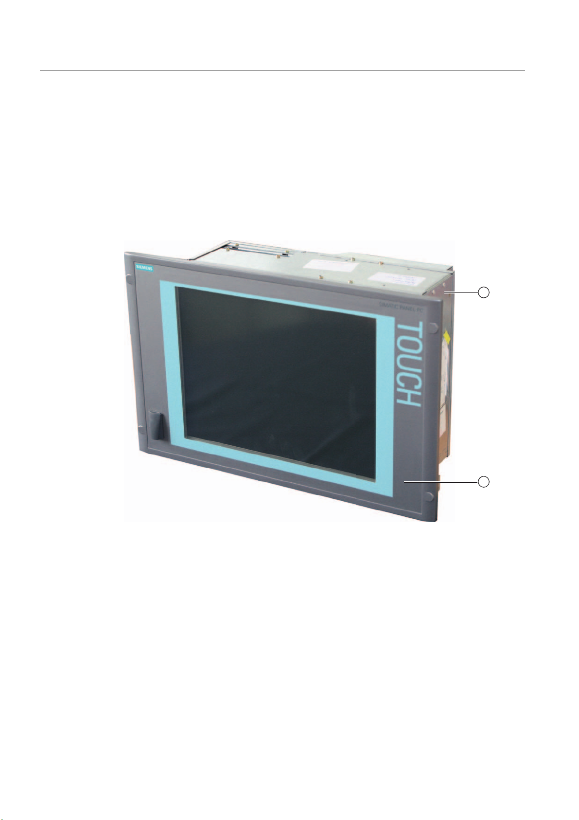
The device serves as a base for PC-based HMI devices, the Panel PCs. The Panel PC 577
fulfills the basic requirements for industrial compatibility and provides high performance at a
low price.
The device consists of the control unit with a key or touch panel and the computer unit. The
control unit is screwed to the back of the computer unit.
Figure 2-1 Panel PC 577
1 Control unit
2 Computer unit
SIMATIC Panel PC 577
2-2 Operating Instructions, Release 04/2006, A5E00798484-01
Page 23

Description
2.3 Technical features
2.3 2.3 Technical features
General features
Processor - Intel® Pentium 4 2.4 GHz
- Intel® Celeron 2.0 GHz
Chipset Intel 865G
Main memory 256 MB = 2 x 128 MB SDRAM or
1 x 256 MB SDRAM
512 MB = 2 x 256 MB SDRAM
4 slots, expandable to 4 GB maximum
Slots for add-ons
Device variants
The device is available with different control
units which are distinguished by the size of the
display and by a membrane keyboard or touch
screen.
Graphics On-board graphics (865G chipset)
Power supply 110/230 V AC, 350 W; variable voltage with short-
Drives optional CD-ROM drive
Hard disks ≥ 40 GB HDD small, 1x 2.5"
Operating system, optional Preinstalled, also installed on the Restore CD
• Uppermost slot is suitable for WinAC Slot
module
• 2 x PCI 175 mm long (below)
Keyboard variants
• 12"/15" TFT technology
• Color display with backlighting
• Membrane keyboard with alphanumeric keys,
numeric keys, cursor keys and control keys
• Function keys and softkeys
• Integrated mouse
• Softkeys, <Shift> und <ACK>
• Front-mounted USB 2.0 interface for
connecting external I/O modules
Touch screen variants
• 12''/15''/19'' TFT technology
• Color display with backlighting
• Front-mounted USB 2.0 interface for
connecting external I/O modules
12'': 800 x 600, 60 Hz
15'': 1024 x 768, 60 Hz
19'': 1280 x 1024, 60 Hz
term buffering against power failure at maximum
16 ms
- Windows 2000 Professional MUI*
- Windows XP Professional MUI*
*MUI: Multi-language user interface; German,
English, French, Italian, Spanish, Japanese,
Korean, Chinese simplified and Chinese
traditional
SIMATIC Panel PC 577
Operating Instructions, Release 04/2006, A5E00798484-01
2-3
Page 24
Description
2.3 Technical features
Interfaces
Installed via expansion cards: PROFIBUS / MPI CP 5611-compatible
(not included in the scope of supply)
Ethernet LAN 10/100/1000 Mbps
USB 4x USB 2.0 high current, external
2x USB 2.0 high current available, internal
via male connector
1x USB 2.0 high current, front mounted
Serial interfaces COM1 V.24
Parallel interfaces LPT1
Keyboard PS/2
Mouse PS/2
Accessories not supplied with the device package
SIMATIC PC
Image Creator SW
Film for protecting the touch screen panel
against dirt and scratches
for the 12" touch screen variant
for the 15" touch screen variant
for the 19" touch screen variant
Labeling strips
for 12" keyboard variant
for 15" keyboard variant
Screw fixing elements
for 19'' touch screen variant
Software for local data backup
6AV7671-2BA00-0AA0
6AV7671-4BA00-0AA0
6AV7672-1CE00-0AA0
6AV7672-0DA00-0AA0
The labeling strips and printing templates can be
obtained from the Internet address mentioned in
the preface.
6AV7672-8KE00-0AA0
SIMATIC Panel PC 577
2-4 Operating Instructions, Release 04/2006, A5E00798484-01
Page 25

Description
2.3 Technical features
SIMATIC Panel PC 577
Operating Instructions, Release 04/2006, A5E00798484-01
2-5
Page 26

Description
2.3 Technical features
SIMATIC Panel PC 577
2-6 Operating Instructions, Release 04/2006, A5E00798484-01
Page 27

Planning use
3.1 3.1 Overview
Introduction
This section describes the first steps after unpacking, the permitted mounting positions and
the fixation. This section describes the necessary considerations for EMC.
Field of application
The Panel PC is an industry-standard PC platform for demanding tasks in the field of PCbased automation. The Panel PC is designed for on-site use on the machine, installed for
example in:
• Control cabinets
• Swivel arms
• In consoles
3
Note
In the following, the term "control cabinet" also refers to rack, mounting rack, switchboard,
operator panel and console. The term "device" represents the Panel PC and its variants.
SIMATIC Panel PC 577
Operating Instructions, Release 04/2006, A5E00798484-01
3-1
Page 28

Planning use
3.2 Unpacking and checking the delivery
3.2 3.2 Unpacking and checking the delivery
Procedure
1. Please check the packaging material for transport damage upon delivery.
2. If any transport damage is present at the time of delivery, lodge a complaint at the
shipping company in charge. Have the shipper confirm the transport damage
immediately.
3. Unpack the device.
Caution
Do not lie the device on its back. This will avoid any damage to an optical drive which
may be present. Lie the front side on a soft surface to avoid damaging the front panel
USB interface.
4. Keep the packaging material in case you have to transport the unit again.
Notice
The packaging protects the device during transport and storage. Therefore, never
dispose of the original packaging material!
5. Please keep the enclosed documentation in a safe place. You will need the
documentation when you start up the device for the first time.
6. Check the package contents for completeness and any visible transport damage. Check
for completeness using the "Contents of Delivery" list in the Operating Instructions
(compact).
7. Notify the delivery service in charge immediately if the packages contents are incomplete
or damaged.
Warning
Make sure that a damaged device is not installed or put into operation.
8. Note the identification information as described in the "Operating Instructions (compact)"
document.
SIMATIC Panel PC 577
3-2 Operating Instructions, Release 04/2006, A5E00798484-01
Page 29

Planning use
3.2 Unpacking and checking the delivery
Warning
Risk of damage
Do not transport the device when it is mounted. During transport, use the hard disk
transport lock (if present).
The device is approved for use with the following operating systems:
Approvals
• Windows 2000 Professional Multi-Language SP4 and higher, German, English, French,
Italian, Spanish, Japanese, Korean, Chinese Simplified and Chinese Traditional
• Windows XP Professional Multi-Language, German, English, French, Italian, Spanish,
Japanese, Korean, Chinese Simplified and Chinese Traditional
Windows XP Professional is only approved as of Service Pack 2.
The operating system is provided with the Windows function modes "Hibernate" and
"Standby" deactivated when shutting down the operating system and with "Fast User
Switch" (Windows XP Professional) deactivated.
SIMATIC Panel PC 577
Operating Instructions, Release 04/2006, A5E00798484-01
3-3
Page 30
Planning use
3.3 Make note of identification data
3.3 3.3 Make note of identification data
Procedure
1. Write down the Microsoft Windows product key of the Certificate of Authenticity COA in
the table at the end of this section. The product key can be found on the back of the
device. You will need the product key during the reinstallation of the operating system.
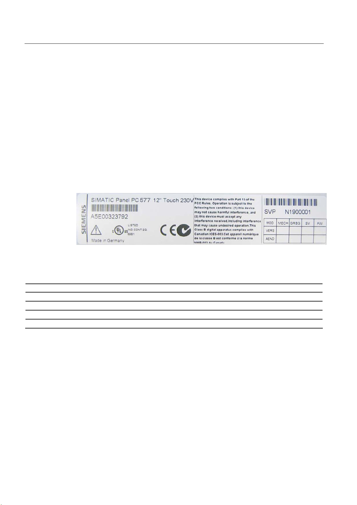
2. Write down the manufacturer's number SVP and the order number , e.g. "6AV782...", in
the table. If repairs are necessary, the device can be identified by the service center on
the basis of the SVP number and order number.
Both numbers can be found on the rating plate attached to the side of the device where
the power unit is located.
Figure 3-1 Rating plate
3. Enter the Ethernet address of the device: The Ethernet address is located in the "Main"
menu of the BIOS setup, "Hardware Options > Ethernet Address."
Identification Number
1 Microsoft Windows Product Key
2 SVP number
3 Order number
10 Ethernet address (MAC address)
SIMATIC Panel PC 577
3-4 Operating Instructions, Release 04/2006, A5E00798484-01
Page 31

Planning use
3.4 EMC directive
3.4 3.4 EMC directive
Electromagnetic compatibility
The device fulfills the requirements of the EMC law of the Federal Republic of Germany as
well as the EMC directive of the Single European Market.
The device is designed as a built-in model with front-sided IP65 degree of protection. Ensure
compliance with the EN 61000-4-2 standard by installing the device in grounded metal
cabinets, e.g. 8 MC cabinets, Siemens catalog NV21.
Note
For additional information about EMC requirements, refer to the Technical data section.
Installing the device according to EMC directive
Basics for interference-free operation:
• Install the controller according to EMC directive
• Use interference-immune cable
Note
The instructions "Guidelines for the assembly of interference-immune programmable logic
controllers" with the article ID 1064706 and the manual "PROFIBUS networks" with the
article ID 1971286, which also applies to the installation of the device, is located on the
"Documentation and Drivers" CD.
SIMATIC Panel PC 577
Operating Instructions, Release 04/2006, A5E00798484-01
3-5
Page 32

Planning use
3.5 Mounting positions and fastening
3.5 3.5 Mounting positions and fastening
3.5.1 Installation instructions
Before mounting the device, read the following general notes relating to installation.
Warning
Dangerous Voltage
Isolate the power supply to the control cabinet before opening it. Ensure that the power to
the control cabinet cannot be turned on accidentally.
Caution
The device is approved for operation in closed rooms only.
• Ensure that the grounding outlet of the building installation is easily accessible and that
there is a mains disconnect switch in control cabinet installations.
• Position the screen in an ergonomic position favorable to the user. Choose a suitable
mounting height.
• Position the screen so that it is not subject to direct sunlight or other strong sources of
light.
• DVD drives are susceptible to shock. Shocks during operation can lead to the loss of data
or damage to the drive or data carrier. Burners and DVDs are not suitable for continous
operation.
• Applies to devices which are installed in swivel arm housings: Avoid rapid or jerky
movements of the swivel arm during operation. The ensuing forces could lead to possible
irreversible damage of the hard disk.
• Provide adequate volume in the control cabinet for air circulation and heat transport.
Keep at least 10 cm distance between the device and control cabinet.
• Do not allow the maximum air intake temperature to exceed 45° C. Decisive is the
temperature measured at a distance of 10 cm from an air intake. The maximum air intake
temperature must be accounted for especially when sizing closed control cabinets.
• Position the device so that the air vents of the housing are not covered up following
mounting.
• Ensure there is enough free space in the control cabinet to allow the sheet metal cover to
be removed. You will otherwise have to remove the device from the control cabinet or
swivel arm when replacing the memory or the battery.
SIMATIC Panel PC 577
3-6 Operating Instructions, Release 04/2006, A5E00798484-01
Page 33

Planning use
3.5 Mounting positions and fastening
• Also provide enough free space to add on to the device.
• Equip the control cabinet with struts for stabilizing the mounting cut-out. Install struts
where necessary.
• Avoid extreme environmental operating conditions. Protect your device against dust,
moisture and heat.
• Install the device in such a way that it poses no danger, e.g. by falling over.
• During assembly, please comply with the approved mounting positions.
Notice
The device must be mounted in a fireproof cabinet to fulfill the requirements for UL508
certification.
To fulfill the requirements for EN 60950, the device must be mounted in a permitted
position.
For additional information, refer to the dimensional drawings in the appendix.
Warning
Function test while installing the device in machines or execute systems
Following the results of a risk analysis, additional protection equipment on the machine or
the system is necessary to avoid endangering persons. With this, especially the
programming, configuration and wiring of the inserted I/O modules have to be executed, in
accordance with the safety performance (SIL, PL or Cat.) identified by the necessary risk
analysis. The intended use of the device has to be ensured.
The proper use of the device has to be verified with a function test on the system. This test
can detect programming, configuration and wiring errors. The test results have to be
documented and, if necessary, entered into the relevant documents that verify safety.
SIMATIC Panel PC 577
Operating Instructions, Release 04/2006, A5E00798484-01
3-7
Page 34

Planning use
3.5 Mounting positions and fastening
3.5.2 Permitted mounting positions
Approval
Only certain mounting positions are approved for the device.
Figure 3-2 Permitted mounting position
The device can be mounted in a vertical position with deviations between +5° and -5° in the
given directions.
3.5.3 Mounting type
The control unit is secured in the mounting cut-out either with clamps or screws.
Notice
Securing with screws is not possible with the 12" touch screen variant.
For securing the 19'' touch screen variant with screws, you will need the accessory with
MLFB No. 6AV7672-8KE00-0AA0
Select the type of mounting suitable to your requirements for the degree of protection.
SIMATIC Panel PC 577
3-8 Operating Instructions, Release 04/2006, A5E00798484-01
Page 35

Planning use
3.5 Mounting positions and fastening
3.5.4 Degree of protection
Principle
The degree of protection provided at the front is assured when the mounting seal lies
completely against the mounting cut-out.
Caution
Please ensure that the material strength at the mounting cut-out is a maximum of 6 mm.
Please follow the specifications for the dimensions in the "Mounting cut-out" section.
The degrees of protection are only guaranteed when the following is observed:
• The material strength at the mounting cut-out is at least 2 mm.
• The surface plane deviation of the mounting cut-out in relation to the external dimensions
of the control unit amounts to ≤ 0.5 mm when the control unit is mounted.
IP65 degree of protection and NEMA4
The IP65 degree of protection and NEMA4 is only provided for clamp mounting together with
a ring seal.
IP54 degree of protection
This degree of protection is assured when fixed using screws and the mounting components
for 19" rack accessories.
Note
For screw fixing of the 19" touch panel front, a backing plate is available as an accessory.
For further information, see "http://mall.ad.siemens.com/
".
SIMATIC Panel PC 577
Operating Instructions, Release 04/2006, A5E00798484-01
3-9
Page 36

Planning use
3.6 Mounting cut-out
3.6 3.6 Mounting cut-out
3.6.1 Selecting and creating the mounting cut-out
Requirement
The degree of protection suitable to the field of application and thereby the mounting method
have been selected.
Procedure
1. Follow the installation instructions.
2. Select a location suitable for installation, taking into account the installation instructions
and the chosen mounting position.
3. On the basis of the dimensional drawings, check whether the required screw and
pressure points on the rear and the hatched seal area are easily accessible after the
completion of the mounting cut-out. Otherwise the mounting cut-out is useless.
4. Complete the mounting cut-out in accordance with the dimensions. You can also obtain
these dimensions from the mounting template supplied with the device.
SIMATIC Panel PC 577
3-10 Operating Instructions, Release 04/2006, A5E00798484-01
Page 37

Planning use
3.6 Mounting cut-out
3.6.2 Dimensions
The following illustration shows the dimensions for the mounting cut-out. You can also obtain
these dimensions from the mounting template supplied with the device.
$
$
6
/
/
/
/ /
/ 6 6 /
66
/ 6 6 /
/
/
/
/
Figure 3-3 Drill holes for the screws and pressure points for the clamp screws
/
PP
(1) Drill hole for screw attachment (4) Clamp
(2) Pressure points for clamp (5) R
(3) Setscrews (6) Seal area
SIMATIC Panel PC 577
Operating Instructions, Release 04/2006, A5E00798484-01
120 in the seal area
Z
3-11
Page 38

Planning use
3.6 Mounting cut-out
Table 3-1 Dimensions for the mounting cut-out in mm
1)
Control
L1 L2 L3
L4
L5 L6
1)
units
Tolerance +1 +1 ±0.2 ±0.2 ±0.5 ±0.5 ±0.5 ±0.5 +1 ±1 ±1 ±1 ±1 ±1 ±1 ±1 ±1 ±1
Key
panels
12" TFT
15" TFT
Touch
screen
panels
12" TFT
15" TFT
450
450
368
450
450
290
321
290
290
380
465
465
—
465
465
235
279
—
235
235
112
112
112
112
112
19" TFT
1)
M6 thread or drill holes with a diameter of 7 mm
2)
Cut-outs for the shafts of the insert strips are only necessary for 15" key panels.
3)
Only for 19" touch panels are two clamps necessary for vertically securing clamps.
—
186
—
—
—
2)
L7
2)
—
135
—
—
—
2)
2)
L8
—
25
—
—
—
L9
A1 A2 S1 S2 S3 S4 S53) S63)S73)
56
78
78
78
78
10
16
—
56
51
51
51
51
17
16
165
56
35
35
35
19
10
16
—
56
81
81
81
81
10
16
—
—
46
46
46
46
10
16
—
—
—
—
—
33
—
—
—
—
33
More information about device dimensions, e.g. mounting depth, can be found in the
"Dimensional drawings" section.
SIMATIC Panel PC 577
3-12 Operating Instructions, Release 04/2006, A5E00798484-01
Page 39

Installation
4.1 4.1 Securing with clamps
Scope
Skip this step if you have selected "screw mounting."
Requirement
Note
The 12" touch screen variant can only be fixed in place using clamps.
• The mounting cut-out has been completed.
• Clamps are readily available in the accessories. Clamps and setscrews are included in
the contents of delivery.
4
Figure 4-1 Clamp assembly
Procedure
1. Follow the installation instructions.
2. Working from the front, insert the device into the mounting cut-out.
3. Secure the control unit in the mounting cut-out from behind with the clamps, as shown in
the mounting cut-out in the dimensions. Tighten the setscrews to a torque of 0.4-0.5 Nm.
SIMATIC Panel PC 577
Operating Instructions, Release 04/2006, A5E00798484-01
4-1
Page 40

Installation
4.2 Securing with screws
4.2 4.2 Securing with screws
Scope
Skip this step if you have selected "clamp mounting."
Requirement
Notice
Securing with screws is not possible with the 12" touch screen variant.
For securing the 19'' touch screen variant with screws, you will need the accessory with
MLFB No. 6AV7672-8KE00-0AA0
The mounting cut-out has been completed.
SIMATIC Panel PC 577
4-2 Operating Instructions, Release 04/2006, A5E00798484-01
Page 41

Installation
4.2 Securing with screws
Procedure
1. Follow the installation instructions.
2. Drill suitable holes at the prepared mounting cut-out in accordance with the specifications
for L4 and L5, as shown in the mounting cut-out in the dimensions.
3. Carefully drill the respective holes in the control unit at the designated location (1) from
the rear.
Figure 4-2 Designated location for holes on the control unit
4. Working from the front, insert the device into the mounting cut-out.
5. Secure the control unit by inserting suitable screws through the holes and attaching nuts.
SIMATIC Panel PC 577
Operating Instructions, Release 04/2006, A5E00798484-01
4-3
Page 42

Installation
4.3 Dimensions
4.3 4.3 Dimensions
The mounting depth increases by 28 mm when a DVD-ROM drive is installed in the device.
Refer to the dimensional drawings in the "Technical specifications" section for the exact
measurements.
SIMATIC Panel PC 577
4-4 Operating Instructions, Release 04/2006, A5E00798484-01
Page 43

Connecting
5.1 5.1 Overview
Introduction
Once you have mounted the device, connect it.
Warning
Do not touch power cables or data transmission cables during electrical storms and do not
connect any cables.
Unplug the mains connector from the socket to be sure the electricity is disconnected.
Caution
Connection sequence
Follow the described sequence when connecting the device to avoid damaging it.
5
Commissioning
Allow the device to adjust to the room temperature before connecting the device. Do no
place the device near direct heat radiation. If moisture condensation occurs, wait at least
about 12 hours before you switch on the device.
Risk of data loss!
Do not disconnect the power supply when the device is in operation. Disconnect the power
only after the device has been correctly shut down.
Requirement
• The device has been installed in conformity with the EMC directive
• The device has been installed according to the information provided in these operating
instructions.
SIMATIC Panel PC 577
Operating Instructions, Release 04/2006, A5E00798484-01
5-1
Page 44

Connecting
5.1 Overview
Procedure
1. Connect the equipotential bonding.
2. Connect peripherals:
– Connect an external monitor if desired.
– Connect the PS/2 mouse.
– Connect the PS/2 keyboard.
– Connect a USB device such as a USB mouse if desired.
– Connect a printer.
3. Connect the power supply.
SIMATIC Panel PC 577
5-2 Operating Instructions, Release 04/2006, A5E00798484-01
Page 45

Connecting
5.2 Interfaces
5.2 5.2 Interfaces
5.2.1 Front interfaces
Introduction
A USB interface is located on the front side. For more information, please refer to the
chapter "Operation." Attach an external keyboard or an external mouse, for example, to the
USB interface. The front-side USB interface supports the standard USB 2.0.
Caution
Wait at least 10 seconds between the unplugging and replugging of USB devices. This also
applies in particular to touch control in control units with touch screen panels.
Notice
When the cover over the USB interface is opened in order to connect a USB component, the
degree of protection for the device is no longer guaranteed.
When using standard USB peripherals, please bear in mind that their EMC immunity level is
frequently designed for office applications only. These devices are adequate for
commissioning and servicing purposes. However, only industry-standard devices are
allowed for industrial operation.
The peripherals are developed and marketed by individual vendors. The respective
manufacturers offer support for the peripherals. Moreover, the terms of liability of the
individual vendors or suppliers apply here.
SIMATIC Panel PC 577
Operating Instructions, Release 04/2006, A5E00798484-01
5-3
Page 46

Connecting
5.2 Interfaces
5.2.2 Rear interfaces
Interfaces
Arrangement of the interfaces
Item Name Description
(1) KEYBOARD Connection for a PS/2 keyboard
(2) Mouse Connection for a PS/2 mouse
(3) USB 2.0 Connection for USB devices
(4) COM 1 Serial interface, 9-pin Sub-D
connector
(5) LPT 1 Parallel interface, 25-pin sub D
socket
(6) VGA VGA connection
(7) USB 2.0 Connection for USB devices
(8) Ethernet RJ 45 Ethernet connection
10/100/1000 Mbps
SIMATIC Panel PC 577
5-4 Operating Instructions, Release 04/2006, A5E00798484-01
Page 47

Connecting
5.2 Interfaces
Power supply
Position of the IEC power connector Description
IEC power connector (2) for the AC power
supply to the device. The maximum
permitted power supply range is 120 V AC
to 230 V AC.
On / Off switch (1)
Note
You can also switch on the device using the soft power key. Refer to the "Operator controls"
chapter for more information.
SIMATIC Panel PC 577
Operating Instructions, Release 04/2006, A5E00798484-01
5-5
Page 48

Connecting
5.3 Connecting peripherals
5.3 5.3 Connecting peripherals
5.3.1 Overview
When connecting the device for the first time, connect a PS/2 keyboard and PS/2 mouse.
Connect any required USB components such as a USB hub.
Caution
Disconnect the device from the power supply before connecting peripherals. This does not
apply to connecting and disconnecting USB devices.
Connect only I/O modules approved for industrial applications according to EN 61000-6-
2:2001. Use shielded cables and metal connectors to connect peripherals. Otherwise, the
specified standards and specifications declared by Siemens AG are no longer valid. Secure
the plugs of the interface cables to the device housing with screws. This improves the
electrical shielding.
Mouse
Connect a PS/2 or USB mouse.
5.3.2 Connecting a monitor
The front panel is activated as the display by default when the operating system starts. An
external monitor connected to the VGA port is therefore deactivated.
Learn how to activate an external monitor by reading the section "Installing and removing
hardware components" in the "Service and maintenance" chapter.
SIMATIC Panel PC 577
5-6 Operating Instructions, Release 04/2006, A5E00798484-01
Page 49

Connecting
5.3 Connecting peripherals
5.3.3 USB
Introduction
Commercially available USB peripherals can be easily and flexibly connected via the USB
interface. For example, you can connect an external USB keyboard and a USB mouse. If the
USB keyboard has a USB interface, you can connect other USB peripherals, such as a USB
mouse, directly to the keyboard.
USB interface
There are several types of USB peripherals:
• Low power devices: maximum 100 mA power consumption, e.g. mouse and keyboard
• High power devices maximum 500 mA power consumption, e.g. hard disk and floppy
drive
Note
The general USB specifications apply to the USB interfaces on the computer unit.
The USB interface on the front panel has been approved for a maximum of one additional
USB hub.
Using USB peripherals
Notice
When installing a USB device for the first time, make sure you have the required device
driver.
Before removing an intelligent USB device, deactivate the device in the operating system
using the dialog "Unplug or Eject Hardware". For additional information, refer to the
documentation for the operating system.
SIMATIC Panel PC 577
Operating Instructions, Release 04/2006, A5E00798484-01
5-7
Page 50

Connecting
5.3 Connecting peripherals
Connecting USB devices
Procedure
Caution
Wait at least 10 seconds between removal and reconnection of USB devices. This also
applies to control units with touch screens, especially for touch operation.
Notice
When using standard USB peripherals, please bear in mind that their EMC immunity level is
frequently designed for office applications only. These devices are adequate for
commissioning and servicing purposes. However, only industry-standard devices are
allowed for industrial operation.
The peripherals are developed and marketed by individual vendors. The respective
manufacturers offer support for the peripherals. Moreover, the terms of liability of the
individual vendors or suppliers apply here. More information about connecting USB devices
is available in the "Commissioning" section.
1. Insert the USB cable into one of the USB interfaces. The device is automatically detected
by the Plug and Play operating system. The operating system may prompt you to install a
driver when necessary.
SIMATIC Panel PC 577
5-8 Operating Instructions, Release 04/2006, A5E00798484-01
Page 51

Connecting
5.4 Connecting the power supply
5.4 5.4 Connecting the power supply
Principle
The device can be optionally operated on 110 or 230 V AC systems. The device features an
automatic voltage switch and a power switch.
Caution
Do not touch power cables or data transmission cables during electrical storms and do not
connect any cables.
Unplug the mains connector from the socket to be sure the electricity is disconnected.
The device features a safety-certified power cable. Connect the device only to a grounding
outlet. Operate the device only on grounded power cables and not on impedance grounding
systems such as IT systems.
Make sure that the local supply voltage complies with the permissible rated voltage for the
device.
Warning
Select an adequately large cable diameter so that the device is not damaged by the cable
during a short circuit.
Localized information
Outside of the USA and Canada, 230 V AC power supply:
If you do not use the safety-certified power cable, use a flexible cable with the following
characteristics:
• At least 18 AWG conductor cross-section
• Grounding plug 15 A, 250 V
Notice
Ensure that the cable set conforms to the respective national safety regulations and is
appropriately labeled.
SIMATIC Panel PC 577
Operating Instructions, Release 04/2006, A5E00798484-01
5-9
Page 52

Connecting
5.4 Connecting the power supply
For USA and Canada:
A UL-listed power supply cable must be used in the United States and Canada.
110V power supply
Use a flexible cable with the following characteristics:
• UL approval
• Type SJT with three conductors
• At least 18 AWG conductor cross-section
• Maximum 4.5 m length
• Parallel grounding plug 15 A, min. 125 V
230V power supply
Use a flexible cable with the following characteristics:
• UL approval
Procedure
• Type SJT with three conductors
• At least 18 AWG conductor cross-section
• Maximum 4.5 m length
• Tandem grounding plug 15 A, min. 250 V
1. Insert the supplied power cable into the AC/DC power socket of the device.
2. Lock the power plug with the interlocking device supplied in the package. This will
prevent unintentional detachment of the IEC power connector on the device.
SIMATIC Panel PC 577
5-10 Operating Instructions, Release 04/2006, A5E00798484-01
Page 53

Connecting
5.5 Uninterruptible AC power supplies
5.5 5.5 Uninterruptible AC power supplies
Introduction
This chapter describes the considerations involved in using an uninterruptible AC power
supply (AC UPS) for the Panel PC.
Due to legal regulations related to reducing reactive-power consumption in public and private
electrical networks, all AC voltage supplies in Panel PCs feature a power factor correction
(PFC) circuit. Technically, there is passive PFC and active PFC.
Active PFC
All Panel PC 87x, Panel PC 577 and Panel PC 677 feature an active PFC. Active PFC
requires almost perfect sinusoidal input voltage.
Caution
Uninterruptible AC power supplies (AC UPS) with non-sinusoidal wave form damage the
power supply unit of Panel PCs with active PFC.
Make that the AC UPS supplies a sinusoidal output voltage in normal and battery mode for
use on a Panel PC with active PFC.
Selection criteria for an uninterruptible power supply
Uninterruptible power supplies with sinusoidal output voltage in normal and battery mode are
classified as "VFI-SS-…" or "VI-SS-…".
UPS characteristics are described and classified in EN 50091-3 and IEC 62040-3.
Note
More information is available on the Internet at "www.ad.siemens.de
Solutions." Click on "Service & Support" under "Services" and search for the article ID
"17241008" on the "Product Support" page. At the end of the article there is a link to the
document, "UPS Classification Based On Operational Performance".
" under "Products &
SIMATIC Panel PC 577
Operating Instructions, Release 04/2006, A5E00798484-01
5-11
Page 54

Connecting
5.6 Connecting the equipotential bonding
5.6 5.6 Connecting the equipotential bonding
A low-resistance ground connection ensures that interference signals generated by external
power supply cables, signal cables or cables to the I/O modules are safely discharged to
ground.
The equipotential bonding connection of the device is located at the connection elements of
the computer unit and is identified by the following symbol:
Figure 5-1 Equipotential bonding
Connecting the equipotential bonding
Required tool for equipotential bonding terminal: TORX T20 screwdriver
Steps for connecting the equipotential bonding
1 Connect the equipotential bonding connection
(M4 thread) on the device (1) (large surface,
large-area contact) with the central grounding
point of the control cabinet.
The minimum conductor cross-section may not
amount to less than 5 mm2.
SIMATIC Panel PC 577
5-12 Operating Instructions, Release 04/2006, A5E00798484-01
Page 55

Connecting
5.6 Connecting the equipotential bonding
Avoiding differences in potential
Differences in potential arise between separated system parts, which in some cases lead to
high equalization currents. This situation may arise if the cable shielding is terminated at
both ends and grounded at different system parts. Potential differences can be caused, for
example, by different power inputs.
Reduce the differences in potential by laying the equipotential bonding cables in such a way
that the affected electronic components function properly. Observe the following guidelines
when setting up equipotential bonding:
• When two system parts are connected by means of a shielded signal cable, and their
shields are both connected to the ground or protective conductor, the following must be
observed: The impedance of the additional equipotential bonding cable amounts to 10%
of the shield impedance, at the most.
• Ensure that the equipotential bonding cable cross-section is selected to accommodate
the maximum equalization current. The equipotential bonding conductor cross-section
that has proven best in practice is 16 mm
• Use equipotential bonding conductors made of copper or galvanized steel. Connect the
cables to the ground or protective conductor over a wide area. Protect the ground or
protective conductor from corrosion.
2
.
• Lay the equipotential bonding cable in such a way that the area between the equipotential
bonding cable and signal cables is as small as possible.
SIMATIC Panel PC 577
Operating Instructions, Release 04/2006, A5E00798484-01
5-13
Page 56

Connecting
5.6 Connecting the equipotential bonding
SIMATIC Panel PC 577
5-14 Operating Instructions, Release 04/2006, A5E00798484-01
Page 57

Connecting
5.6 Connecting the equipotential bonding
SIMATIC Panel PC 577
Operating Instructions, Release 04/2006, A5E00798484-01
5-15
Page 58

Page 59

Commissioning
6.1 6.1 Removing the transport lock for the hard disk
Note
Not every device has a hard disk transport lock.
To enhance the ruggedness of the SIMATIC Panel PC 577 during shipping, the device is
fitted with a transport lock for the hard disk. This comprises two knurled screws that clamp
the hard disk to prevent undesirable vibrations. The hard disk transport lock is located on the
top of the SIMATIC Panel PC 577 and is marked with an adhesive label. When shipped, the
transport lock is locked. Before you switch on the device for the first time, you must remove
the transport lock for the hard disk.
6
SIMATIC Panel PC 577
Operating Instructions, Release 04/2006, A5E00798484-01
6-1
Page 60

Commissioning
6.1 Removing the transport lock for the hard disk
Removing the transport lock for the hard disk
Procedure for removing the transport lock for the hard disk
(1) Unscrew 2 knurled screws (1) by hand
+DUG' LVN7UDQVSRUW VLFKHUXQ J
ELWWHYRUGHU, QEHWULHEQ DKPH
HQWIHUQH Q[5¦QGHOVFKUDXEHQ
3OHDVHUHPRYHW KHKDUGGLVN
WUDQVSRU WORFNEHIR UHRSHUDWLQ J
(2) Screw the knurled screws into the nuts on the rear of the device for safe-keeping.
Notice
Risk of damage
If you do not remove the hard disk transport lock before starting up the device, the SIMATIC
Panel PC 577 may suffer damage.
Notice
Fitting the hard disk transport lock again
Transport the device only in the original packaging. Fit the hard disk transport lock again for
this purpose: Switch off the device and place it in the operating position. Screw in the knurled
screws as far as the stop.
SIMATIC Panel PC 577
6-2 Operating Instructions, Release 04/2006, A5E00798484-01
Page 61

Commissioning
6.2 Overview
6.2 6.2 Overview
Checklist
Before starting up the device for the first time, go through the following checklist:
• Have you taken into account the proper ambient and environmental conditions for the
device and the connected I/O modules, as described in the technical information?
• Have you removed the hard disk transport lock?
• Have you learned how to connect the equipotential bonding?
• Have you learned how to connect the power supply?
• Read over this information in the respective "Connecting" chapter of the operating
instructions. Please follow all guidelines.
Caution
Condensation
• When transporting the device at low temperatures, ensure that no moisture gets on or
in the device. This also applies if the device is subjected to extreme changes in
temperature. Wait 12 hours before switching the device on.
• Allow the device to slowly adjust to room temperature before commissioning the
device. Do not subject the device to direct heat radiation from devices such as
heaters.
Peripheral devices
• Use shielded cables and metal connectors to connect peripherals. Otherwise, the
specified standards and specifications declared by Siemens AG are no longer valid.
Secure the plugs of the interface cables to the device housing with screws. This
improves the electrical shielding.
Startup
• Do not switch off the device during the initial startup. Otherwise, parts of the software
which are necessary for trouble-free operation will be lost.
• Use the standard settings in the BIOS as described in the "Detailed Descriptions"
chapter of the operating instructions under the section "BIOS setup", "BIOS setup
default settings." Otherwise the operating system will not be installed properly.
Requirement
• A PS/2 mouse is connected.
• A PS/2 keyboard is connected.
SIMATIC Panel PC 577
Operating Instructions, Release 04/2006, A5E00798484-01
6-3
Page 62

Commissioning
6.2 Overview
Procedure
1. Switch on the device.
2. Install Microsoft Windows operating system.
3. Install the applications and drivers.
SIMATIC Panel PC 577
6-4 Operating Instructions, Release 04/2006, A5E00798484-01
Page 63

Commissioning
6.3 Switching on the device.
6.3 6.3 Switching on the device.
Procedure
1. Plug the mains connector of the supplied power supply cable in the AC power supply
connector of the device.
2. Screw on the lock for the mains connector (1).
Figure 6-1 Lock mains connector
3. Lock the mains connector in place as shown in the illustration.
4. Plug the power supply cable into a socket with a grounded protective conductor.
5. Switch on the power switch of the device.
The device starts up and boots. If it does not, use a pointed object to press the soft power
key.
Note
Soft power key
For further instructions on using the soft power key, refer to the section "Operator control
/ Command elements".
SIMATIC Panel PC 577
Operating Instructions, Release 04/2006, A5E00798484-01
6-5
Page 64

Commissioning
6.3 Switching on the device.
Self-test
After connection to the power supply, the device performs a self test. During the self test,
the message "Press <F2> to enter SETUP" appears briefly.
When the self-test is finished, the operating system will be loaded.
SIMATIC Panel PC 577
6-6 Operating Instructions, Release 04/2006, A5E00798484-01
Page 65

Commissioning
6.4 Setting up the Microsoft Windows operating system
6.4 6.4 Setting up the Microsoft Windows operating system
Introduction
The setup wizard appears immediately following the startup of the device. The wizard is
used to set the parameters of the operating system.
Procedure
Note
The dialogs of the setup wizards differ slightly in some places for the Windows 2000
Professional and Windows XP Professional operating systems.
In order to change to the next dialog, click on the ">>" button. In order to change the entry in
the previous dialog, click on the "<<" button.
1. Accept the Microsoft licensing agreement.
2. Leave the regional settings of the operating system unchanged. If required, adjust the
regional settings of the operating system only after commissioning.
3. Enter the company names and user names.
4. If this PC name is already in use as you attempt to connect the device to a network: Enter
a new PC name for identification.
The operating system will restart automatically.
The system settings are updated. The desktop is set up. The setup of the operating system
is complete.
SIMATIC Panel PC 577
Operating Instructions, Release 04/2006, A5E00798484-01
6-7
Page 66

Commissioning
6.5 Installing applications and drivers, Touch-Base
6.5 6.5 Installing applications and drivers, Touch-Base
Introduction
After the device is restarted, different dialogs appear on the screen. Drivers and applications
can be installed from these dialogs.
Additional hardware and software components
You can install and configure additional hardware and software components such as a
network. For additional information, refer to the documentation of the hardware and software.
Note
The directory "c:\i386" contains special Windows components for subsequent installation.
Energy-saving mode
The "Suspend timeout" option is disabled by default in the "Power" menu of the BIOS setup.
Caution
Do not activate the "Suspend timeout" option! The safe operation of the automatic plant or
system is otherwise no longer guaranteed.
The "Suspend timeout" BIOS option is not an authorized function.
SIMATIC Panel PC 577
6-8 Operating Instructions, Release 04/2006, A5E00798484-01
Page 67

Commissioning
6.5 Installing applications and drivers, Touch-Base
Procedure
1. In the "Panel Wizard" dialog, click the type of panel that corresponds to your device.
Figure 6-2 Panel Wizard, selection of the panel type
2. In the "Panel Wizard Touch" dialog, click on the screen size that corresponds to your
device. The screen resolution is set correspondingly for the device.
SIMATIC Panel PC 577
Operating Instructions, Release 04/2006, A5E00798484-01
6-9
Page 68

Commissioning
6.5 Installing applications and drivers, Touch-Base
Figure 6-3 Panel Wizard Touch, selection of the screen size
The next step only applies to control units with touch screen panels.
Once the screen size is selected, the wizard will search for new hardware, the touch
controller. The Panel Wizard closes and the Touch-Base-25-point touch calibration
appears. Carry out the following steps carefully.
SIMATIC Panel PC 577
6-10 Operating Instructions, Release 04/2006, A5E00798484-01
Page 69

Commissioning
6.5 Installing applications and drivers, Touch-Base
3. Briefly touch the touch screen at every cross hair.
Figure 6-4 Touch screen calibration
4. The following only applies to control units with key panels: Exit the operating system
session and restart the device. Otherwise the "Security features" from "KeyTools" will not
be activated.
Warning
Use "KeyTools" as described in the "Additional drivers and applications" section of the
"Operation and configuration" chapter.
The following applies when the "Security features" of "KeyTools" is deactivated:
When the additional function keys and softkeys F13 to S16 are used, or when using your
own key code table, serious malfunctions of the user software can occur because the key
codes behind the function keys can also be activated by pressing keys other than the
configured ones.
5. No administrator password is assigned in the factory state. When the logon dialog
appears the next time the device starts up, therefore, leave the field empty and close the
dialog with the "OK" button.
Notice
Then configure an administrator password for security.
SIMATIC Panel PC 577
Operating Instructions, Release 04/2006, A5E00798484-01
6-11
Page 70

Commissioning
6.5 Installing applications and drivers, Touch-Base
The installation of the drivers and applications is complete. Further information is available in
the "Operation and configuration" chapter of the operating instructions under the section,
"Additional drivers and applications."
Notice
After starting up your device, find out more about the particulars of the operating system in
the chapter "Start-up" in the device's operating instructions under the section, "Microsoft
Windows operating systems". Further information is available in the chapter "Service and
maintenance" under the section, "Installing software."
SIMATIC Panel PC 577
6-12 Operating Instructions, Release 04/2006, A5E00798484-01
Page 71

Commissioning
6.6 Notes about new installation of Windows 2000
6.6 6.6 Notes about new installation of Windows 2000
Service pack
After a new installation of Windows 2000, install at least Service Pack 4. Service Pack 4 is
supplied in the product package.
Note
If you are using SIMATIC WinCC or SIMATIC WinCC flexible, pay heed to the operating
system releases. For additional information, refer to the SIMATIC WinCC and SIMATIC
WinCC flexible documentation.
Automatic updates
The "Automatic updates" function is installed with Service Pack 3 or later for Windows 2000.
Call
Start menu "Start", command "Settings > Control panel > Automatic Updates"
You can deactivate this function in the dialog "Automatic Updates" "Keep my computer up to
date". With this setting enabled, ….
Updates will then no longer be performed automatically on the device via the Internet.
Notice
When the check-box is activated, updates will be installed automatically on the device via the
Internet even when they have not been released by Siemens AG.
SIMATIC Panel PC 577
Operating Instructions, Release 04/2006, A5E00798484-01
6-13
Page 72

Commissioning
6.6 Notes about new installation of Windows 2000
SIMATIC Panel PC 577
6-14 Operating Instructions, Release 04/2006, A5E00798484-01
Page 73

Operation and configuration
7.1 7.1 Normal operation
7.1.1 Switching the device on and off
Switching on the device
Requirement
• The I/O modules, e.g. mouse and keyboard, have been connected.
Caution
Use shielded cables and metal connectors to connect peripherals. Otherwise, the
specified standards and specifications declared by Siemens AG are no longer valid.
Secure the plugs of the interface cables to the device housing with screws. This improves
the electrical shielding.
7
Follow the guidelines in the "Interfaces" section of the chapter "Connecting."
• The operating system and the service packs have been installed and set up on the hard
disk of the device. For additional information, please refer to the chapter "Start-up" in the
computer unit operating instructions.
• The pre-installed drivers and applications have been set up appropriately. For more
information, please refer to the chapter "Additional drivers and applications."
• The proper ambient and environmental conditions according to the technical data for the
device and the connected I/O modules have been observed.
SIMATIC Panel PC 577
Operating Instructions, Release 04/2006, A5E00798484-01
7-1
Page 74

Operation and configuration
7.1 Normal operation
Procedure
Warning
Danger of maloperation!
The following applies to external input devices or combinations of external input devices and
control units with key panels: Ambiguous key codes can cause serious malfunctions of the
application program.
Always activate the "Security features" of "KeyTools." Please follow the relevant safety
instructions in the chapter "Additional drivers and applications."
Caution
If moisture condensation occurs, wait at least about 12 hours before you switch on the
device.
1. Connect the device to the power mains.
2. Plug the power supply cable of the device into a socket with a grounded protective
conductor.
3. Switch on the power switch of the device.
The device is now in operation and booting.
Caution
Risk of data loss!
Do not switch off the power supply when the device is in operation. Disconnect the power
only after the device has been correctly shut down.
After switching on the power supply, the device performs a self-test. During the self test,
the message "Press <F2> to enter SETUP" appears briefly.
When the self-test is finished, the operating system will be loaded and the desktop will be
displayed.
The booting process has been completed successfully.
SIMATIC Panel PC 577
7-2 Operating Instructions, Release 04/2006, A5E00798484-01
Page 75

Operation and configuration
7.1 Normal operation
Switching off the device
Shut down the operating system correctly before switching off the device.
Caution
Wait for the display to go dark.
Then switch off the power switch of the device.
Warning
Always pull out the power cable to isolate the device from the mains.
SIMATIC Panel PC 577
Operating Instructions, Release 04/2006, A5E00798484-01
7-3
Page 76

Operation and configuration
7.2 Additional drivers and applications
7.2 7.2 Additional drivers and applications
7.2.1 Overview
The necessary drivers and applications are contained in the supplied "Documentation and
Drivers" CD.
Note
The supplied drivers and applications have been system-tested and are approved for this
device. No warranty can be provided for other software.
Press the "Help" button to obtain information concerning the buttons of a dialog.
SIMATIC Panel PC 577
7-4 Operating Instructions, Release 04/2006, A5E00798484-01
Page 77

Operation and configuration
7.2 Additional drivers and applications
7.2.2 Setting the touch screen
Call
• Start menu "Start", command "Programs > UPDD > Settings"
Function
Recalibrates the touch screen.
If the touch screen does not react as expected when touched, repeat the calibration. To do
this, first activate the 25 point calibration and then calibrate the touch screen.
Figure 7-1 Touch defaults, "Calibration" tab
Note
For further information press the "Help" button.
SIMATIC Panel PC 577
Operating Instructions, Release 04/2006, A5E00798484-01
7-5
Page 78

Operation and configuration
7.2 Additional drivers and applications
Special features
Note
When the edges of the touch screen are used intensively, it is recommended that 25 point
calibration is performed instead of the 9 point calibration.
Warning
Maloperation
If you touch the touch screen while the screen saver is active, the SIMATIC process
visualization software, e.g. WinCC, will carry out the functions which happen to be behind it.
Caution
Only touch one point on the touch screen and not several points at one time. You may
otherwise trigger unintended reactions.
Do not touch the screen in the following situations:
— When the device is booting until the boot process is completed
— When plugging or unplugging USB components
— While Scandisk is running
—During calibration of the touch screen
USB keyboard controller
The USB keyboard controller supports the following additional functions for key models:
• Keyboard programming with the "KeyTools" application
• Adjustment of the backlighting brightness with the application "SetBrightness."
• Control of the key LEDs
The USB keyboard controller must be installed before this function can be used. For
installation instructions, see the description on the "Documentation and Drivers" CD.
SIMATIC Panel PC 577
7-6 Operating Instructions, Release 04/2006, A5E00798484-01
Page 79

Operation and configuration
7.2 Additional drivers and applications
7.2.3 KeyTools
Call
Start menu "Start", command "Settings > Control panel > SIMATIC Key Tools"
Function
SIMATIC KeyTools is one selection of the applications for Panel PC. With it, key codes
which are sent from the key panel of the control unit are adjusted. A description of the
"KeyTools" is located in the "Help" menu, and more information is located in the menu "Info >
About."
"KeyTools" consists of the following tools:
• "Keycode table", previously "KeyPad": Loading and editing of key code tables.
• "WinCC hotkey function", previously "KeyHook": WinCC hotkey function activation und
deactivation.
• "Security features": prevents two function keys from being activated simultaneously. This
prevents incorrect operations and undefined states of the user program.
Warning
For security reasons, always use "Security features". Do not deactivate "Security
features".
The following applies when the "Security features" of "KeyTools" is deactivated:
When the additional function keys and softkeys F13 to S16 are used, or when using your
own key code table, serious malfunctions of the user software can occur because the key
codes behind the function keys can also be activated by pressing keys other than the
configured ones. Further information is available in the description of "KeyTools" on the
supplied "Documentation & Drivers" CD.
SIMATIC Panel PC 577
Operating Instructions, Release 04/2006, A5E00798484-01
7-7
Page 80

Operation and configuration
7.2 Additional drivers and applications
7.2.4 SystemGuard
Call
"SystemGuard" icon in the message field. SystemGuard is activated automatically after the
device is started.
Function
SystemGuard indicates temperatures, fan speeds and voltages.
Example
Notice
SystemGuard is a freeware tool for which Siemens AG offers no technical support. Observe
the notes in the online help of the application.
In the "Temperatures" tab you can see the current temperature of the CPU for the first and a
second processor and the internal temperature of the device. The motherboard's on-board
sensor supplies this information. An optional AUX sensor is also available.
This shows the current temperature. The current temperature and range are displayed
graphically.
Figure 7-2 SystemGuard
SIMATIC Panel PC 577
7-8 Operating Instructions, Release 04/2006, A5E00798484-01
Page 81

Operation and configuration
7.2 Additional drivers and applications
7.2.5 TouchInput
Call
"TouchInput" symbol on the desktop.
Function
TouchInput provides a screen keyboard. On the screen keyboard, the characters are entered
directly on the touch screen or with the mouse.
Figure 7-3 TouchInput
SIMATIC Panel PC 577
Operating Instructions, Release 04/2006, A5E00798484-01
7-9
Page 82

Operation and configuration
7.2 Additional drivers and applications
7.2.6 CheckLanguageID
Scope
The following applies to Windows 2000 Professional Multi-Language and Windows XP
Professional Multi-Language.
Call
c:\drivers\checklang\checklangid.exe or reinstallation from the "Documentation and Drivers"
CD.
Function
"CheckLanguageID" displays the currently installed languages.
Figure 7-4 CheckLanguageID
• SystemDefaultLangID: System language
• UserDefaultLangID: Standard language
• UserDefaultUILangID: User interface language
Notice
All three languages displayed should have the same ID assigned.
SIMATIC Panel PC 577
7-10 Operating Instructions, Release 04/2006, A5E00798484-01
Page 83

Operation and configuration
7.2 Additional drivers and applications
7.2.7 Multilingual settings for the operating system
Windows MultiLanguage MUI operating system enables users to set the language of the GUI
to their individual preference. Some elements are not localized, however, and remain in the
original language of the system - English.
You should therefore always install English language service packs. Further information
about the language of the GUI, regional settings and inputs is available in the Internet at
http://support.microsoft.com.
Setting up the language selection for Windows 2000 Professional
The Multilanguage User Interface (MUI) allows you to set up the Windows 2000 Professional
menus and dialogs for additional languages.
To set the required languages for the Windows 2000 Professional menus, dialogs and
keyboard layout, select:
Start > Settings > Control Panel > Regional Options > General tab, Setting for current user field and
Language settings for the system field and the Keyboard layout field in the Input locales tab.
In addition to the menu and dialog language settings, you also need to set the default
language by selecting Set Default... from the Regional Options dialog box.
The default language setting of your Windows 2000 Professional installation is English and a
US keyboard layout. To change to another language and keyboard layout, open the Control
Panel and select:
Start > Settings > Control Panel > Regional Options >General tab, Setting for current user field and
Language settings for the system field and the Input language field in the Input Locales tab.
Setting up the language selection for Windows XP Professional
The Multilanguage User Interface (MUI) allows you to set up the Windows XP Professional
menus and dialogs for additional languages.
Default language of your Windows XP Professional MUI installation is English and a US
keyboard layout. You can change the language in the Control Panel. Select:
Start > Control Panel > Date, Time, Language, and Regional Options > Add other languages >
Languages tab,Language used in menus and dialogs field.
For the Date, Time, Language and Regional Options set the default as non-Unicode
programs under Advanced in addition to the language for menus and dialogs.
SIMATIC Panel PC 577
Operating Instructions, Release 04/2006, A5E00798484-01
7-11
Page 84

Operation and configuration
7.2 Additional drivers and applications
SIMATIC Panel PC 577
7-12 Operating Instructions, Release 04/2006, A5E00798484-01
Page 85

Operating
8.1 8.1 Operator controls
On / Off switch
On / Off switch Description
The device is on when the power switch (1) is in position "0". Voltage is
supplied to the device even when it is switched off.
8
Warning
The On / Off switch does not disconnect the device from mains.
SIMATIC Panel PC 577
Operating Instructions, Release 04/2006, A5E00798484-01
8-1
Page 86

Operating
8.1 Operator controls
"Soft power" key
"Soft power" key Description
The soft power key (1) can trigger two shutdown functions during active
operation:
1) Correct shutdown of the operating system and shutdown of the device
To perform this function, press the key briefly with a pointed object.
2) Immediate switch-off of the device without correct shutdown of the
operating system
This function is used to shut down the device when it no longer responds.
Press the key for approximately 4 seconds with a pointed object.
Caution: Data loss
Although this function does not trigger a hardware reset, loss of data
cannot be ruled out as a result.
Then you can start the device again in one of two ways:
1) Restart via soft power key
If you wait at least 7 s after shutdown and then press the key, the device
will boot again.
2) Restart via On/Off switch
After shutdown, place the On/Off switch in Position 0 and wait for at least
7 s. Then, when you place the On/Off switch in Position 1, the device will
boot up again.
SIMATIC Panel PC 577
8-2 Operating Instructions, Release 04/2006, A5E00798484-01
Page 87

Operating
8.2 Operator controls on key panels
8.2 8.2 Operator controls on key panels
8.2.1 Overview
The device has the following keypads:
• 2 x 8 vertical keypads with softkey functions
• 2 x 10 horizontal keypads with function keys F1 -F20
The number of keys, their labeling and function is the same on all key panels. The various
panel types differ only in the arrangement of the keys and in the size and type of the display.
The following figure is therefore only an example using the front view of the 12" variant.
Figure 8-1 Example of a 12" control unit with key panel
1 Display
2 Function keys, softkeys
3 Alphanumeric, numeric, cursor keys and control keys
4 Integrated mouse
5 USB interface
SIMATIC Panel PC 577
Operating Instructions, Release 04/2006, A5E00798484-01
8-3
Page 88

Operating
8.2 Operator controls on key panels
8.2.2 Keyboard
Principle
The layout of the membrane keyboard is "English/USA international."
Warning
Maloperation
If you activate several keys simultaneously, a malfunction on the device cannot be excluded.
Activate function keys and softkeys only in sequence! Use "KeyTools" as described in the
chapter "Additional drivers and applications."
Applies after the deactivation of the "security features" of "Key Tools" or after the
deinstallation of "KeyHook":
Overview
When the additional function keys and softkeys F13 to S16 are used, or when using your
own key code table, serious malfunctions of the user software can occur because the key
codes behind the function keys can also be activated by pressing keys other than the
configured ones.
Activating a key using a hard object, e.g. a screwdriver, reduces the life of the key.
The keyboard is divided into different functional groups:
• Function keys and softkeys
• Control keys
• Alphanumeric keys
• Numeric keys
• Cursor keys
SIMATIC Panel PC 577
8-4 Operating Instructions, Release 04/2006, A5E00798484-01
Page 89

Operating
8.2 Operator controls on key panels
Function keys and softkeys
The softkeys are arranged on the left and on the right, and the function keys in a double row
below the display.
Figure 8-2 Function keys and softkeys
Control keys
The control keys activate editing functions and control functions in different applications:
1 Backspace
2 Open Help
3 Toggling between the pre-defined key
assignment and special characters,
arithmetic symbols and signs
4 Acknowledge
7$%
+(/3
)
$
6+,)7
(6&
&75/
$&.
(17(5
$/7
35,17
,16
'(/
1
Alphanumeric keys
Enter letters, special characters, blank spaces and underline using the alphanumeric keys.
SIMATIC Panel PC 577
Operating Instructions, Release 04/2006, A5E00798484-01
1 Underline
2 Blank
8-5
Page 90

Operating
8.2 Operator controls on key panels
Numeric keys
Enter the numerals "0" to "9" and special characters, e.g. the decimal point, using the predefined assignment of the numeric keys.
Figure 8-3 Numeric keys
Enter special characters, arithmetic signs and signs
Special characters, arithmetic signs and signs are also assigned to most of the alphanumeric
and numeric keys. These signs are indicated by white symbols on the top left of the keys. To
enter such a sign, proceed as follows:
1. Hold down the <FN> key.
2. Activate the desired alphanumeric or numeric key at the same time. The displayed
special character, arithmetic sign or signs will be entered.
3. To enter the signs of the pre-defined assignment again, release the <FN> key.
Cursor keys
Navigate, scroll or move the writing mark using the cursor keys. The cursor keys correspond
to the usual keys of the PC keyboard.
1 <Left> key
2 <Up> key
3 <Right> key
4 <Down> key
5 <Pos 1> key
6 <Page up> key
7 <Page down> key
SIMATIC Panel PC 577
8-6 Operating Instructions, Release 04/2006, A5E00798484-01
Page 91

Operating
8.2 Operator controls on key panels
External keyboards
The keyboard layout has been set to "English/USA international." If you use a keyboard with
a layout other than the "English/USA international" layout, the key codes of the internal and
external keyboards might no longer correspond.
8.2.3 Labeling function keys and softkeys
Scope
This section applies only to control units with key panels.
Introduction
The control unit has two horizontal and two vertical keypads Assign user specific functions to
the keys as needed and mark them using labeling strips.
DIN A4 film is available for the production and insertion of the labelling strips, as described
under Service and Maintenance in the options. You will find printer templates for the labeling
strips on the "Documentation and Drivers" CD.
Procedure
Warning
Labeling
Label the function keys and softkeys to conform with the project. Labeling without reference
to a project leads to incorrect operations on the system to be observed.
1. Label the DIN A4 film with a laser printer using the printing templates from the
"Documentation and Drivers" CD.
2. Cut the labeling strips along the pre-printed lines.
Note
Do not insert handwritten labeling strips until the ink has dried.
3. Insert the labeling strips from the rear side of the control unit. The highlighted elements in
the following illustrations show the slits provided and the corresponding sections of the
labeling strips.
SIMATIC Panel PC 577
Operating Instructions, Release 04/2006, A5E00798484-01
8-7
Page 92

Operating
8.2 Operator controls on key panels
3DUW
Figure 8-4 12" device: Rear of the control unit with connectors and slots for the labeling strips
3DUW
3DUW3DUW3DUW3DUW
3DUW3DUW
3DUW 3DUW 3DU W 3DUW
Figure 8-5 15" device: Rear of the control unit with connectors and slots for the labeling strips
SIMATIC Panel PC 577
8-8 Operating Instructions, Release 04/2006, A5E00798484-01
Page 93

Operating
8.3 Operator controls of the touch screen panels
8.3 8.3 Operator controls of the touch screen panels
8.3.1 Overview
The 12", 15" and 19" variants differ in their dimensions and the size of the display. The 12''
and 19'' variants do not have side drill hole covers.
The following figure is therefore only an example using the front view of the 15" variant.
Figure 8-6 Example of a 15" touch screen panel
1 Display
2 USB interface
SIMATIC Panel PC 577
Operating Instructions, Release 04/2006, A5E00798484-01
8-9
Page 94

Operating
8.3 Operator controls of the touch screen panels
8.3.2 Touch screen
The display is sensitive to touch and application-specific surface elements, e.g. a button,
appear on the screen. By tapping the button with your finger, the function assigned to the
button is activated.
Caution
Only touch one point on the touch screen and not several points at one time. You may
otherwise trigger unintended reactions.
Do not touch the screen in the following situations:
— When the device is booting until the boot process is completed
— When plugging or unplugging USB components
— While Scandisk is running
The following types of pressure are permissible:
• Using a plastic pen with a 1 mm radius at the point: 25 g.
• Using a silicone finger with a diameter of 1.6 cm: 50 g.
SIMATIC Panel PC 577
8-10 Operating Instructions, Release 04/2006, A5E00798484-01
Page 95

Operating
8.4 DVD-ROM drive
8.4 8.4 DVD-ROM drive
Introduction
The DVD-ROM or DVD burner drive is used to install software during commissioning or
when servicing a device.
Figure 8-7 CD-ROM drive
1 Access LED
2 Eject key
3 Emergency removal aperture
4 Tray
Emergency removal
An emergency removal involves removing a CD when the tray is blocked or there is no
power for the drive. In this case the tray can be moved manually instead of motor-driven
Procedure
1. Ensure that the power to the drive is really interrupted. Switch off the device.
2. Insert a long thin prong such as a bent paper clip, maximum 1.3 mm thick and at least 55
mm long, into the emergency removal aperture.
3. Carefully open the tray with as little pressure as necessary and then pull it out of the
drive.
4. Pull the tray out until the CD is easily accessible.
5. Remove the CD.
SIMATIC Panel PC 577
Operating Instructions, Release 04/2006, A5E00798484-01
8-11
Page 96

Operating
8.5 Transferring authorizations
8.5 8.5 Transferring authorizations
Note
The device has no floppy disk drive. Therefore, transfer the authorizations for SIMATIC HMI
software from a USB floppy disk drive.
The following devices have been tested:
SINUMERIK FLOPPY DISK DRIVE, order number 6FC5235-0AA05-1AA2
Caution
The USB floppy disk drive is only suitable when mounted in a control cabinet.
SIMATIC Panel PC 577
8-12 Operating Instructions, Release 04/2006, A5E00798484-01
Page 97

Integration in TIA
9.1 9.1 Industrial communications
Introduction
The following options are available for integrating the device in existing or planned system
environments and networks.
Ethernet
The integrated Ethernet interface can be used for communication and for data exchange with
automation devices such as SIMATIC S7.
You need a suitable software package for this. STEP7, WinCC, ProTool, WinCC flexible,
WinAC, SIMATIC NET.
PROFIBUS / MPI
The potentially isolated Profibus interface can be used to connect distributed field devices or
to couple with SIMATIC S7.
9
You require suitable software for this: STEP7, WinCC, ProTool, WinCC flexible, WinAC,
SIMATIC NET.
Profinet
Additional information
For further information, refer to the catalog and to the online ordering system of Siemens
A&D.
Internet address: https://mall.ad.siemens.com
SIMATIC Panel PC 577
Operating Instructions, Release 04/2006, A5E00798484-01
9-1
Page 98

Integration in TIA
9.2 PROFIBUS/MPI interface and WinAC card
9.2 9.2 PROFIBUS/MPI interface and WinAC card
Note
You can use a CP 5613 communication module for the PROFIBUS/MPI interface. A
PROFIBUS/MPI interface is also provided on WinAC cards.
You can find further information in the documentation for the CP 5613 communication
module and in the "Servicing and maintenance" chapter under the section "Installing and
removing hardware components", "PCI/WinAC cards".
SIMATIC Panel PC 577
9-2 Operating Instructions, Release 04/2006, A5E00798484-01
Page 99

Servicing and maintenance
10.1 10.1 Servicing
Scope of maintenance
When working in areas where there is dust that may be hazardous to functionality, the
device must be operated in a control cabinet with a heat exchanger or with suitable supply
air.
Note
The dust deposits must be removed at appropriate time intervals.
Maximum dust content in the air circulating in the cabinet
Suspended component 0.2 mg/m3
Deposits 1.5 mg/m3/h
10
Cleaning agents
Use dish soap or foaming screen cleaner only as cleaning agents.
Caution
Do not clean the device with aggresive solvents or scrubbing agents or with pressurized air
or steam cleaner.
SIMATIC Panel PC 577
Operating Instructions, Release 04/2006, A5E00798484-01
10-1
Page 100

Servicing and maintenance
10.1 Servicing
Chemical resistance
Procedure
Caution
Adhere to the information regarding chemical resistance of the panel front. Please refer to
the "Tools & Demosoftware" Internet site for more information. Enter "Chemical resistance"
as the search term. The available articles are displayed.
1. Switch off the device. This prevents the accidental triggering of functions when the screen
is touched.
2. Dampen the cleaning cloth.
3. Spray the cleaning agent on the cloth and not directly on the device.
4. Clean the device with the cleaning cloth.
SIMATIC Panel PC 577
10-2 Operating Instructions, Release 04/2006, A5E00798484-01
 Loading...