

Siemens SIMATIC Panel PC 677, SIMATIC Panel PC 877 Operating Instructions Manual

_
_
_
_
_
_
_
_
_
_
_
_
_
SIMATIC PC Panel PC 677/877, Control Unit
SIMATIC PC
Panel PC 677/877, Control Unit
Operating Instructions
Preface
Safety Information
_____________
Description
_____________
Application planning
_____________
Installation
_____________
Connecting
_____________
Operation
_____________
1
2
3
4
5
6
Operating and parametrizing
_____________
Maintenance and service
_____________
Technical specifications
_____________
Dimensional Drawings
_____________
Appendix
_____________
ESD guidelines
_____________
List of abbreviations
_____________
7
8
9
10
A
B
C
Edition 04/2005
A5E00407724-01
Safety Guidelines
This manual contains notices you have to observe in order to ensure your personal safety, as well as to prevent
damage to property. The notices referring to your personal safety are highlighted in the manual by a safety alert
symbol, notices referring to property damage only have no safety alert symbol. These notices shown below are
graded according to the degree of danger.
Danger
indicates that death or severe personal injury will result if proper precautions are not taken.
Warning
indicates that death or severe personal injury may result if proper precautions are not taken.
Caution
with a safety alert symbol, indicates that minor personal injury can result if proper precautions are not taken.
Caution
without a safety alert symbol, indicates that property damage can result if proper precautions are not taken.
Notice
indicates that an unintended result or situation can occur if the corresponding information is not taken into
account.
If more than one degree of danger is present, the warning notice representing the highest degree of danger will
be used. A notice warning of injury to persons with a safety alert symbol may also include a warning relating to
property damage.
Qualified Personnel
The device/system may only be set up and used in conjunction with this documentation. Commissioning and
operation of a device/system may only be performed by qualified personnel. Within the context of the safety notes
in this documentation qualified persons are defined as persons who are authorized to commission, ground and
label devices, systems and circuits in accordance with established safety practices and standards.
Prescribed Usage
Note the following:
Warning
This device may only be used for the applications described in the catalog or the technical description and only in
connection with devices or components from other manufacturers which have been approved or recommended
by Siemens. Correct, reliable operation of the product requires proper transport, storage, positioning and
assembly as well as careful operation and maintenance.
Trademarks
All names identified by ® are registered trademarks of the Siemens AG. The remaining trademarks in this
publication may be trademarks whose use by third parties for their own purposes could violate the rights of the
owner.
Copyright Siemens AG 2005. All rights reserved.
The distribution and duplication of this document or the utilization and transmission of its
contents are not permitted without express written permission. Offenders will be liable for
damages. All rights, including rights created by patent grant or registration of a utility
model or design, are reserved.
Siemens AG
Automation and Drives
Postfach 4848, 90327 Nuremberg, Germany
Siemens Aktiengesellschaft A5E00407724-01
Disclaimer of Liability
We have reviewed the contents of this publication to ensure consistency with the
hardware and software described. Since variance cannot be precluded entirely, we cannot
guarantee full consistency. However, the information in this publication is reviewed
regularly and any necessary corrections are included in subsequent editions.
© Siemens AG 2005
Technical data subject to change

Preface
Purpose of this manual
This manual provides information based on the requirements defined by DIN 8418 regarding
mechanical engineering documentation. This information relates to the device, its place of
use, transport, storage, installation, use and maintenance.
This manual is intended for the following target groups:
• Users
• Commissioning engineers
• Service technicians
• Maintenance technicians
Please read the section "Safety instructions and general notes" carefully.
Basic knowledge required
A solid background in personal computers and Microsoft operating systems is required to
understand this manual. General knowledge in the field automation control engineering is
recommended.
Scope of the manual
This manual applies to devices with the following order numbers:
• 6AV780…
• 6AV781…
Changes in Comparison to the Previous Version
Panel PC 677 and 877 supplement the Panel PC 670 and 870 product range. The 19" touch
screen panel is also new, the 10" key panels is not applicable. The USB port now supports
USB 2.0. The distributed configuration has been stored in a separate document, apart from
the manual.
Approvals
For more information, please refer to the chapter "Certificates and Guidelines" in the
appendix.
SIMATIC PC Panel PC 677/877, Control Unit
Operating Instructions, Edition 04/2005, A5E00407724-01
i

Preface
CE label
For more information, please refer to "Directives and Declarations" in the "Certificates and
Guidelines" section of the operating instructions for the computer unit.
Standards
Please refer to sections "Application Planning" and "Technical Specifications".
Position in the information landscape
The documentation for the Panel PC includes the following sections:
• SIMATIC Panel PC 677, QuickStart,
SIMATIC Panel PC 877, QuickStart with the following information:
– Startup
– Legal information
• SIMATIC Panel PC 677/877, Operating Instructions for Control Unit, this document
with the following information:
– Operation
– Fault diagnostics
– Hardware
Referred to as "operating instructions for the control unit" in the following.
• SIMATIC Panel PC 677 Operating Instructions for Computer Unit,
SIMATIC Panel PC 877, Operating Instructions for the Computer Unit with the following
information:
– Expansion options
– Configuration
– Fault diagnostics
– Hardware
Referred to as "operating instructions for the computer unit" in the following.
• SIMATIC Panel PC 677/877 distributed, QuickStart with the following information on
distributed configuration
– Assembling
– Installation
– Startup
– Legal information
The documentation is supplied with the Panel PC in electronic form as a PDF file on the
"Documentation & Drivers" CD. QuickStart is also included in printed form. The
documentation is available in German, English, French, Italian and Spanish.
Additional information about the Windows operating system is available in the Internet at the
Microsoft homepage, "http://www.Microsoft.com
SIMATIC PC Panel PC 677/877, Control Unit
ii Operating Instructions, Edition 04/2005, A5E00407724-01
".
Preface
Conventions
The following text notation will facilitate reading this manual:
Notation Scope
"File"
"File > Edit" Operational sequences, e.g., menu commands/shortcut menu
<F1>, <Shift>+<F1> Keys and key combinations
• Terminology that occurs in the user interface, e.g., dialog
names, tabs, buttons, menu commands.
• Inputs required, e.g., limit values, tag values
• Path information
commands.
The term "Panel PC 677/877", "control unit" and "computer unit" is uniformly refered to as
the "device" in these operating instructions. The full term is only used when a concrete
reference is necessary.
Note
A note is important information about the product, handling the product or a reference to
specific sections of the documentation that require special consideration.
Registered trademarks
All names labeled with ® symbol are registered trademarks of Siemens AG. Other names
used in this documentation may be trademarks, the use of which by third parties for their
own purposes could violate the rights of the owner.
HMI®
SIMATIC®
SIMATIC HMI®
SIMATIC ProTool®
SIMATIC WinCC®
SIMATIC WinCC flexible®
Panel PC 677®
Panel PC 877®
Panel PC IL77®
SIMATIC PC Panel PC 677/877, Control Unit
Operating Instructions, Edition 04/2005, A5E00407724-01
iii

Preface
SIMATIC PC Panel PC 677/877, Control Unit
iv Operating Instructions, Edition 04/2005, A5E00407724-01

Table of contents
Preface ........................................................................................................................................................i
1 Safety Information................................................................................................................................... 1-1
1.1 General safety notes.................................................................................................................. 1-1
1.2 General Notes ............................................................................................................................ 1-2
2 Description.............................................................................................................................................. 2-1
2.1 Panel PC 677: Computer unit and control unit .......................................................................... 2-1
2.2 Panel PC 877: Computer unit and control unit .......................................................................... 2-2
2.3 Accessories................................................................................................................................ 2-4
3 Application planning................................................................................................................................ 3-1
3.1 Overview .................................................................................................................................... 3-1
3.2 Unpacking and checking the delivery unit ................................................................................. 3-1
3.3 Make note of identification data ................................................................................................. 3-2
3.4 Guidelines for Handling Electrostatic Sensitive Devices (EMC)................................................ 3-3
3.5 Mounting positions and fastening .............................................................................................. 3-4
3.5.1 Installation notes ........................................................................................................................ 3-4
3.5.2 Permitted mounting positions..................................................................................................... 3-5
3.5.3 Type of fixation........................................................................................................................... 3-6
3.5.4 Degree of protection .................................................................................................................. 3-6
3.6 Mounting cut-out ........................................................................................................................ 3-6
3.6.1 Select and complete recessed mounting cut-out....................................................................... 3-6
3.6.2 Dimensions ................................................................................................................................ 3-7
4 Installation .............................................................................................................................................. 4-1
4.1 Securing with clamps ................................................................................................................. 4-1
4.2 Securing with screws ................................................................................................................. 4-2
4.3 Dimensions ................................................................................................................................ 4-2
5 Connecting ............................................................................................................................................. 5-1
5.1 Front ports.................................................................................................................................. 5-1
5.2 Other interfaces ......................................................................................................................... 5-1
6 Operation...................................................................................................................
6.1 Status displays ........................................................................................................................... 6-1
6.2 Operator controls on key panels................................................................................................ 6-1
6.2.1 Overview .................................................................................................................................... 6-1
6.2.2 Keyboard.................................................................................................................................... 6-2
6.2.3 Labelling function keys and softkeys ......................................................................................... 6-5
6.2.4 Integrated mouse ....................................................................................................................... 6-7
SIMATIC PC Panel PC 677/877, Control Unit
Operating Instructions, Edition 04/2005, A5E00407724-01
............................. 6-1
v

Table of contents
6.3 Operator controls of the touch screen panels............................................................................ 6-7
6.3.1 Overview .................................................................................................................................... 6-7
6.3.2 Touch screen ............................................................................................................................. 6-8
7 Operating and parametrizing .................................................................................................................. 7-1
7.1 Startup........................................................................................................................................ 7-1
7.1.1 Overview .................................................................................................................................... 7-1
7.1.2 Switching on the device ............................................................................................................. 7-2
7.1.3 Setting up the Microsoft Windows operating system ................................................................. 7-3
7.1.4 Installing applications and drivers .............................................................................................. 7-3
7.2 Normal operation........................................................................................................................ 7-8
7.2.1 Turning on device....................................................................................................................... 7-8
7.2.2 Turning off the device................................................................................................................. 7-9
7.3 Additional drivers and applications .......................................................................................... 7-10
7.3.1 Overview .................................................................................................................................. 7-10
7.3.2 Setting the touch screen .......................................................................................................... 7-10
7.3.3 Windows Security Center......................................................................................................... 7-12
7.3.4 KeyTools .................................................................................................................................. 7-13
7.3.5 SOMATIC SOM Safecard on Motherboard.............................................................................. 7-14
7.3.6 TouchInput ............................................................................................................................... 7-14
7.3.7 Set brightness .......................................................................................................................... 7-15
7.3.8 CheckLanguageID ................................................................................................................... 7-15
7.3.9 Multilingual settings for the operating system.......................................................................... 7-16
7.3.10 DVD ROM/CD RW................................................................................................................... 7-17
7.3.11 USB keyboard controller driver and USB stack ....................................................................... 7-18
8 Maintenance and service........................................................................................................................ 8-1
8.1 Service ....................................................................................................................................... 8-1
8.2 Maintenance and replacement parts..........................................................................................8-2
8.3 Separating the control unit from the computer unit.........
........................................................... 8-2
8.3.1 Separating Panel PC 677........................................................................................................... 8-2
8.3.2 Separating Panel PC 877........................................................................................................... 8-4
8.3.3 Remount the device ................................................................................................................... 8-6
9 Technical specifications.......................................................................................................................... 9-1
9.1 EMC requirements ..................................................................................................................... 9-1
9.2 General specifications................................................................................................................ 9-2
9.3 Ambient and environmental conditions...................................................................................... 9-3
9.4 USB port..................................................................................................................................... 9-3
9.5 Keyboard table ........................................................................................................................... 9-4
10 Dimensional Drawings.......................................................................................................................... 10-1
10.1 Panel PC 677 dimensional drawing ......................................................................................... 10-1
10.2 Panel PC 877 dimensional drawing ......................................................................................... 10-3
A Appendix.................................................................................................................................................A-1
A.1 Certificates and guidelines.........................................................................................................A-1
A.1.1 Certificates and approvals..........................................................................................................A-1
A.1.2 Approvals ...................................................................................................................................A-2
A.2 Additional support ...................................................................................................................... A-3
SIMATIC PC Panel PC 677/877, Control Unit
vi Operating Instructions, Edition 04/2005, A5E00407724-01

Table of contents
B ESD guidelines.......................................................................................................................................B-1
B.1 ESD Directives...........................................................................................................................B-1
C List of abbreviations................................................................................................................................C-1
C.1 Abbreviations .............................................................................................................................C-1
Glossary
Index
Tables
Table 3-1 Measurements for the mounting cut-out in mm ......................................................................... 3-7
Table 10-1 Panel PC 677 dimensions in mm............................................................................................. 10-2
Table 10-2 Panel PC 877 dimensions in mm............................................................................................. 10-4
SIMATIC PC Panel PC 677/877, Control Unit
Operating Instructions, Edition 04/2005, A5E00407724-01
vii

Table of contents
SIMATIC PC Panel PC 677/877, Control Unit
viii Operating Instructions, Edition 04/2005, A5E00407724-01
Safety Information
1.1 1.1 General safety notes
Warning
Emergencies
If the device malfunctions, remove the power cable immediately and contact your nearest
customer service representative. Malfunctions can occur when the operator controls or
power cable are damaged or when liquids or foreign objects penetrate the device.
Electrical connections
Warning
Unplug the device before every intervention and after disconnecting it from the power
supply.
Do not touch power lines or data transmission lines during electrical storms and do not
connect any cables.
1
High frequency radiation
Handling and disposal of lithium batteries
Caution
Unintentional operating situations
High frequency radiation, e.g. from cell phones, can cause unintentional operating situations
under some circumstances. For more details, consult the technical data in the "EMC
Requirements" chapter.
Warning
Danger of explosion and the release of harmful substances!
Do not throw lithium batteries into fire, do not solder onto the cell body, do not open, do not
short circuit, do not reverse pole, do not heat above 100 °C, dispose of according to
regulations, and protect from direct sunlight, moisture and condensation.
Replace lithium batteries with the same brand or a brand recommended by the
manufacturer.
Dispose of used lithium batteries individually as hazardous waste in accordance with the
local regulations.
SIMATIC PC Panel PC 677/877, Control Unit
Operating Instructions, Edition 04/2005, A5E00407724-01
1-1

Safety Information
1.2 General Notes
1.2 1.2 General Notes
Overview
Transport
Caution
The device is approved for operation in closed rooms only. The guarantee is void if this
stipulation is ignored.
Avoid extreme environmental operating conditions. Protect your device against dust,
moisture and heat. For additional information, refer to the specifications.
Do not place the device in direct sunlight.
Unpack the device at the its installation location. Transport the device only in the original
packaging. Do not transport the device when it is mounted.
Notice
Adhere to these stipulations each time the device is transported, otherwise the guarantee is
void.
Software Tools & Downloads
Caution
Condensation
When transporting the device in low temperatures, ensure that no moisture gets on or in the
device. This also applies if the device is subjected to extreme changes in temperature.
Commissioning
Allow the device to slowly adjust to room temperature before commissioning the device. Do
no place the device near heat radiation. If moisture condensation occurs, wait at least about
12 hours before you switch on the device.
Vibration
CD/DVD drives are sensitive to vibration. Prohibited vibration during operation may result in
loss of data or damage to the drive or data medium.
Before transporting the device, wait at least 20 seconds to allow the drive to stop completely.
Please check regularly if updates and hotfixes are available for download to your device.
Downloads are available on the Internet at "http://www2.automation.siemens.com/hmi
"Support". Click on "Software Tools & Downloads" on "Overview Panel PCs" Using the
global search function, you can search for any downloads you require.
" under
Chemical resistance
SIMATIC PC Panel PC 677/877, Control Unit
1-2 Operating Instructions, Edition 04/2005, A5E00407724-01
Caution
Adhere to the notes regarding chemical resistance. Please refer to the "Software Tools &
Downloads" Internet site for more information. Enter "Chemical resistance" as the search
item. The available articles are displayed.

Safety Information
1.2 General Notes
Sources of light
Faulty pixels in the display
TFT-LC display
Notice
Position the screen so that it is not subject to direct sunlight or other strong sources of light.
At present, the manufacturing process of modern displays does not guarantee that all pixels
of the display will be perfect. A small number of faulty pixels in the display, is therefore
unavoidable. This does not present a functional problem as long as the faulty pixels are not
bunched in one location.
Refer to the "Technical Specifications" chapter for more information.
A permanent picture with bright images can lead to a burn-in effect on the TFT LCD.
If a screen saver is activated, please observe the following:
• The liquid crystals in screen savers which actuate active black when the backlighting is
on, e.g. flying stars "starfield simulation," renew themselves. Pay attention to the length of
time the backlighting is activated.
• The following applies to screen savers which turn off the the backlighting: Each time the
backlighting is turned on, its life is reduced by 50 minutes.
Consider the following carefully:
• Screen saver
• Switch off the backlighting regularly
• Permanent display of the customer application
SIMATIC PC Panel PC 677/877, Control Unit
Operating Instructions, Edition 04/2005, A5E00407724-01
1-3

Safety Information
1.2 General Notes
SIMATIC PC Panel PC 677/877, Control Unit
1-4 Operating Instructions, Edition 04/2005, A5E00407724-01
Description
2.1 2.1 Panel PC 677: Computer unit and control unit
Structure
The device is available in two different configurations:
• Centralized configuration: Computer unit and control unit form an entity.
• Distributed configuration: Computer unit and control unit are in separate locations.
Principle
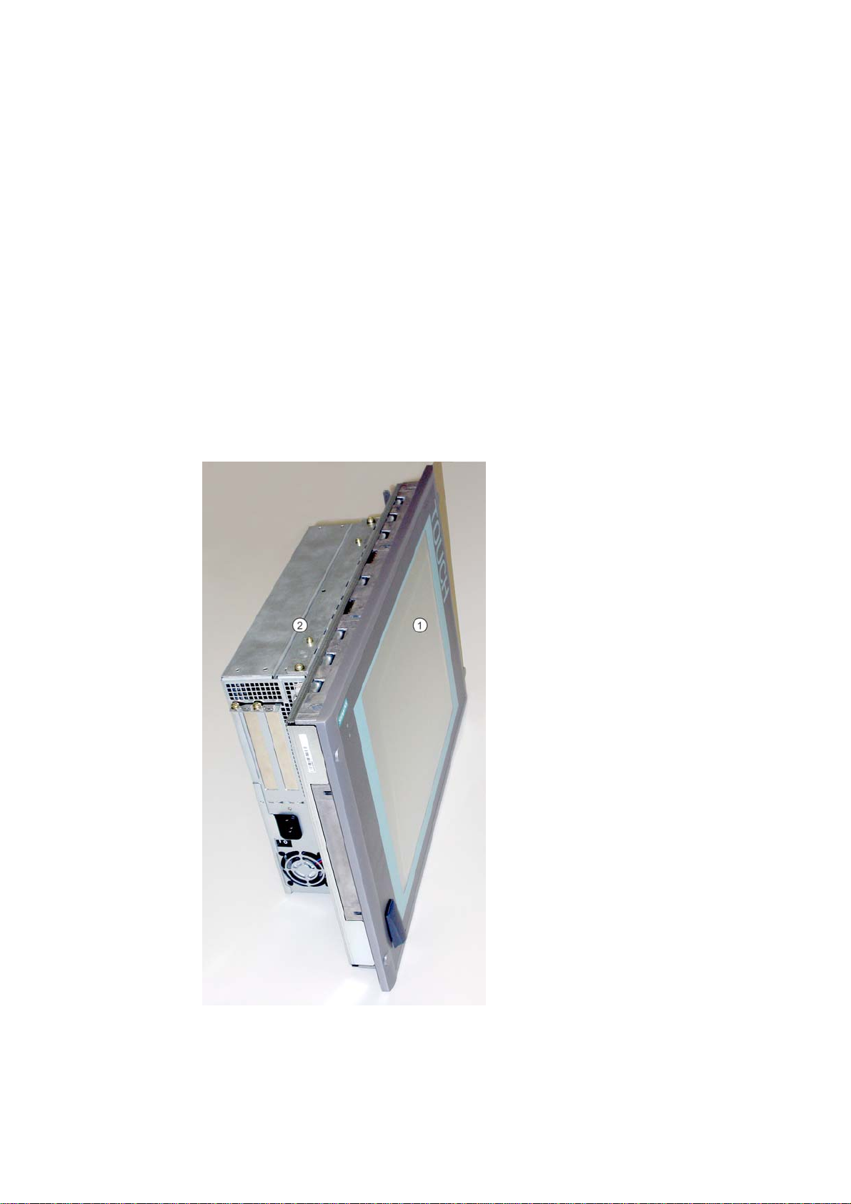
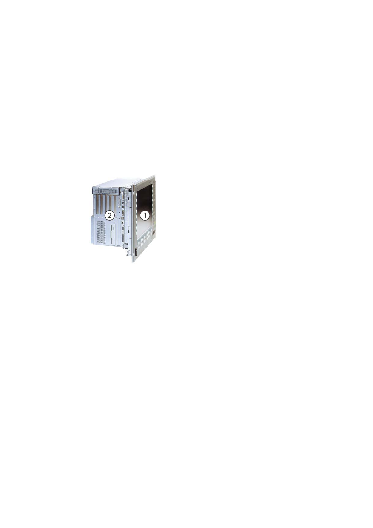
In a centralized configuration, the computer is secured to the back of the control unit with two
mounting rails.
2
Figure 2-1 Panel PC 677 as a complete device with centralized configuration
1 Control unit
2 Computer unit
SIMATIC PC Panel PC 677/877, Control Unit
Operating Instructions, Edition 04/2005, A5E00407724-01
2-1

Description
2.1 Panel PC 677: Computer unit and control unit
Short description
The device is available with different control units which are distinguished by the size of the
display and by the membrane keyboard or touch screen.
Keyboard variants
• Color display with backlighting:
– 12'' TFT technology with 800 x 600 resolution
or
– 15'' TFT technology with 1024 x 768 resolution
• Membrane keyboard with alphanumeric keys, numeric keys, cursor keys and control keys
• Function keys and softkeys
• Integrated mouse
• LEDs for power supply, temperature, softkeys, <Shift> and <ACK> keys
• Front-mounted USB 2.0 port for connecting external I/O modules. The front-mounted
USB port is sealed and unusable for some device variations.
Touch screen variants
• Color display with backlighting
– 12" TFT technology; resolution 800 x 600 pixels
– 15" TFT technology; 1024 x 768 resolution
– 19" TFT technology; 1280 x 1024 resolution
• LEDs for power supply and temperature
• Front-mounted USB 2.0 port for connecting external I/O modules. The front-mounted
USB port is sealed and unusable for some device variations.
For additional information, refer to the specifications.
or
SIMATIC PC Panel PC 677/877, Control Unit
2-2 Operating Instructions, Edition 04/2005, A5E00407724-01
Description
2.2 Panel PC 877: Computer unit and control unit
2.2 2.2 Panel PC 877: Computer unit and control unit
Structure
The device is available in two different configurations:
• Centralized configuration: Computer unit and control unit form an entity.
• Distributed configuration: Computer unit and control unit are in separate locations.
Principle
In a centralized configuration, the computer is secured to the back of the control unit with two
mounting rails.
Short description
Keyboard variants
Figure 2-2 Panel PC 877 as a complete device with centralized configuration
1 Control unit
2 Computer unit
The device is available with different control units which are distinguished by the size of the
display and by the membrane keyboard or touch screen.
• Color display with backlighting:
– 12'' TFT technology with 800 x 600 resolution
or
– 15'' TFT technology with 1024 x 768 resolution
• Membrane keyboard with alphanumeric keys, numeric keys, cursor keys and control keys
• Function keys and softkeys
• Integrated mouse
• LEDs for power supply, temperature, softkeys, <Shift> and <ACK> keys
• Front-mounted USB 2.0 port for connecting external I/O modules. The front-mounted
USB port is sealed and unusable for some device variations.
SIMATIC PC Panel PC 677/877, Control Unit
Operating Instructions, Edition 04/2005, A5E00407724-01
2-3
Description
2.3 Accessories
Touch screen variants
• Color display with backlighting
– 15" TFT technology; 1024 x 768 resolution
– 19" TFT technology; 1280 x 1024 resolution
• LEDs for power supply and temperature
• Front-mounted USB 2.0 port for connecting external I/O modules. The front-mounted
USB port is sealed and unusable for some device variations.
For additional information, refer to the specifications.
2.3 2.3 Accessories
Components
The options comprise the following components:
Accessories Order no.
Direct control key submodule 6AV7671-7DA00-0AA0
Film for protecting the touch screen panel against dirt and
scratches
for the 12" touch screen variant
for the 15" touch screen variant
for the 19" touch screen variant
Film for labeling the function keys
*)
6AV7672-0DA00-0AA0
6AV7671-2BA00-0AA0
6AV7671-4BA00-0AA0
6AV7672-1CE00-0AA0
*) You can also find the labeling strips on the Internet site under "Software Tools &
Downloads", see "General Notes" in the "Safety Information" section. Enter "Labeling strips"
as the search item.
SIMATIC PC Panel PC 677/877, Control Unit
2-4 Operating Instructions, Edition 04/2005, A5E00407724-01

Application planning
3.1 3.1 Overview
Introduction
This section describes the first steps after unpackaging, the permitted mounting positions
and the fixation. This section describes the necessary considerations for EMC.
Field of application
The Panel PC is an industry-standard PC platform for demanding tasks in the field of PCbased automation. The Panel PC is designed for on-site use on the machine, installed for
example in:
• Switchgear cabinets
• Swivel arms (booms)
• In consoles
Note
In the following, the term "switchgear cabinet" also refers to rack, mounting rack,
switchboard, operator panel and console. The term "device" represents the Panel PC and
its variants.
3
3.2 3.2 Unpacking and checking the delivery unit
Procedure
1. Please check the packaging material for transport damage upon delivery.
2. If any transport damage is present at the time of delivery, lodge a complaint at the
shipping company in charge. Have the shipper confirm the transport damage
immediately.
3. Unpack the device.
SIMATIC PC Panel PC 677/877, Control Unit
Operating Instructions, Edition 04/2005, A5E00407724-01
Caution
Do not lie the device on its back. This will avoid any damage to an optical drive which
may be present. Lie the front side on a soft surface to avoid damaging the front panel
USB port.
3-1

Application planning
3.3 Make note of identification data
4. Keep the packaging material in case you have to transport the unit again.
Notice
The packaging protects the device during transport and storage. Therefore, never
dispose of the original packaging material!
5. Please keep the enclosed documentation in a safe place. You will need the
documentation when you start up the device for the first time.
6. Check the package contents for completeness and any visible transport damage. Check
for completeness using the enclosed "Contents of Delivery" list.
7. Notify the delivery service in charge immediately if the packages contents are incomplete
or damaged.
Warning
Make sure that a damaged device is not installed nor put into operation.
8. Note the identification information as described in the "QuickStart" document.
3.3 3.3 Make note of identification data
Procedure
1. Write down the Microsoft Windows Product Key of the Certificate of Authenticity COA in
the table at the end of this section. The product key is located on the power supply cover
of the computer unit. You will need the product key during the reinstallation of the
operating system.
2. Write down the manufacturer's number SVP and the order number of the computer unit,
e.g. "6AV..." in the table. If repairs are necessary, the device can be identified by the
service center on the basis of the SVP number and order number.
Both numbers are located on the rating label of the computer unit at the top of the
ventilator side.
Figure 3-1 Rating label of the computer unit, example
SIMATIC PC Panel PC 677/877, Control Unit
3-2 Operating Instructions, Edition 04/2005, A5E00407724-01
Application planning
3.4 Guidelines for Handling Electrostatic Sensitive Devices (EMC)
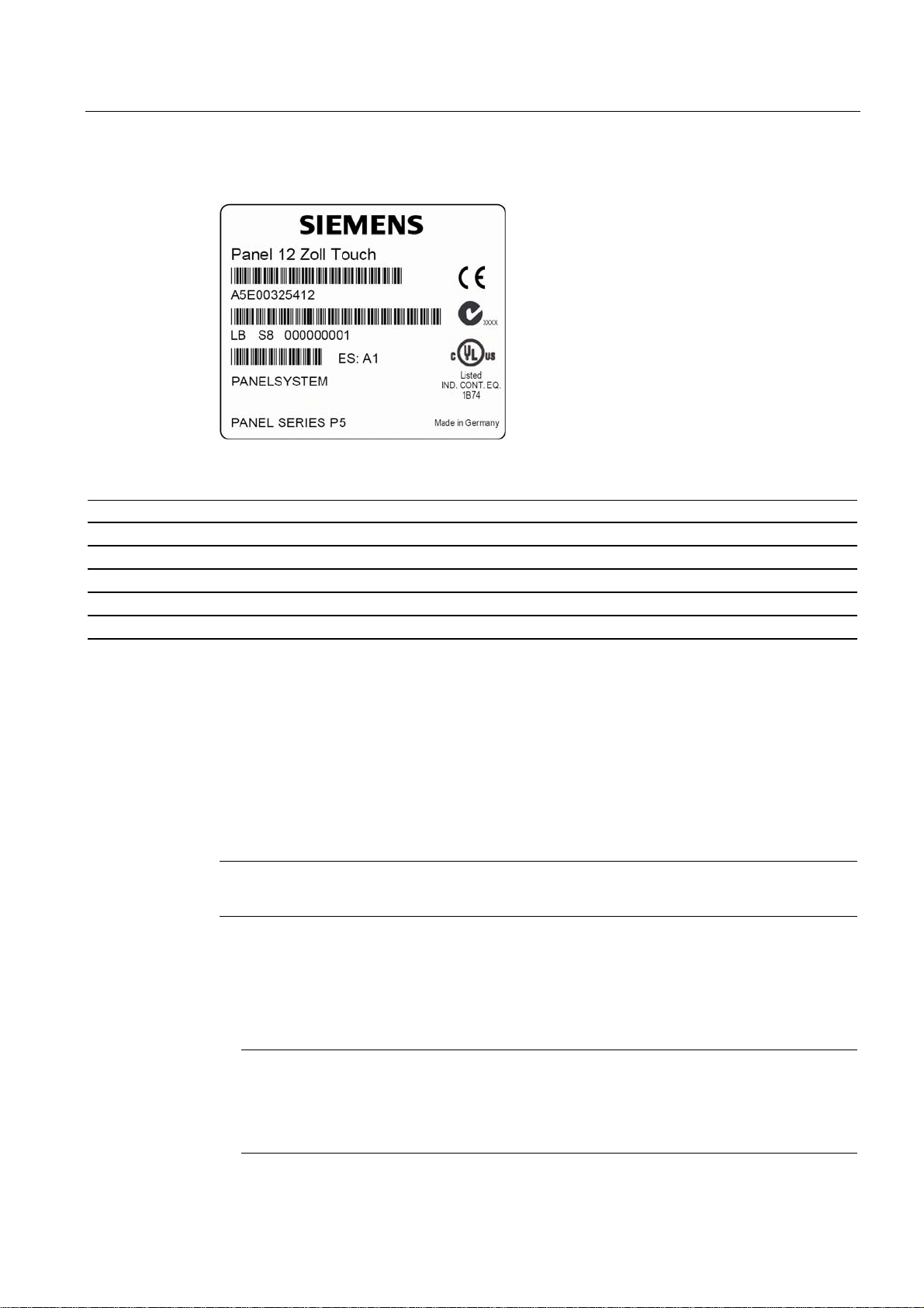
3. Enter the order number of the control unit, for example "A5E…", in the table. You can find
the number on the rating label of the control unit.
Figure 3-2 Rating label of the operator unit, example
4. Enter the Ethernet address of the device: The Ethernet address is located in the "Main"
menu of the BIOS setup, "Hardware Options > Ethernet Address."
Identifier Number
1 Microsoft Windows Product Key COA
2 SVP number
3 Order number of the computer unit
4 Operator unit order number
5 Ethernet address
3.4 3.4 Guidelines for Handling Electrostatic Sensitive Devices (EMC)
Electromagnetic compatibility
The device fulfills the requirements of the EMC law of the Federal Republic of Germany as
well as the EMC Guidelines of the Single European Market.
The device is designed as a built-in model with front-sided Protection Class IP 65. Ensure
compliance with the EN 61000-4-2 standard by installing the device in grounded metal
cabinets, e.g. MC cabinets, Siemens catalog NV21.
Installing the device according to EMC guidelines
Note
Please refer to the appendix for for more information concerning the EMC requirements.
Principles of interference-free operation:
• Installing the controls according to EMC guidelines
• Using interference immune cable
Note
The instructions "Guidelines for the assembly of interference immune programmable logic
controllers" with the article ID 1064706 and the manual "PROFIBUS networks" with the
article ID 1971286, which also applies to the installation of the device, is located on the
"Documentation and Drivers" CD.
SIMATIC PC Panel PC 677/877, Control Unit
Operating Instructions, Edition 04/2005, A5E00407724-01
3-3

Application planning
3.5 Mounting positions and fastening
3.5 3.5 Mounting positions and fastening
3.5.1 Installation notes
Before installing the device, read the following general notes relating to installation.
Warning
Danger, high voltage
Isolate the power supply to the switchgear cabinet before opening it. Make sure that the
power to the switchgear cabinet cannot be turned on accidentally.
Caution
The device is approved for operation in closed rooms only.
• Ensure that the protective contact socket of the building installation is easily accessible
and that there is a central power disconnector in switchgear cabinet installations.
• Position the screen in an ergonomic position favorable to the user. Choose a suitable
installation height.
• Position the screen so that it is not subject to direct sunlight or other strong sources of
light.
• CD/DVD drives are susceptible to shocks. Shocks during operation can lead to the loss of
data or damage to the drive or data carrier. Burners and CD/DVD are not suitable for
continous operation.
• Applies to devices which are installed in swivel arm housings: Avoid rapid or jerky
movements of the swivel arm during operation. The ensuing forces could lead to possible
irreversible damage of the hard disk.
• The device with DC power supply is considered an open means of operation on the part
of the voltage supply. Therefore, make sure that the switchgear cabinet fulfills the the
requirements of a fire protection housing.
Note
The computer unit with AC power supply fulfills the requirements of a fire protection
housing according to EN60950. Therefore, no additional fire protection is necessary for
the installation.
• Provide adequate volume in the switchgear cabinet for air circulation and heat transport.
Keep at least 10 cm distance between the device and switchgear cabinet.
• Do not allow the maximum air intake temperature to exceed 45 °C. Decisive is the
temperature measured at a distance of 10 cm from an air intake. The maximum air intake
temperature must be accounted for especially when sizing closed switchgear cabinets.
• The minimum distance between the device and the housing is 10 cm on the air output
side at the ventilator.
• Position the device so that the air vents of the housing are not covered up following
installation.
SIMATIC PC Panel PC 677/877, Control Unit
3-4 Operating Instructions, Edition 04/2005, A5E00407724-01
Application planning
3.5 Mounting positions and fastening
• Ensure there is enough free space in the switchgear cabinet to allow the sheet metal
cover to be removed. You will otherwise have to remove the device from the switchgear
cabinet or boom when replacing memory or the battery.
• Also provide enough free space to add on to the device.
• Equip the switchgear cabinet with struts for stabilizing the installation cut-out. Install struts
where necessary.
• Avoid extreme environmental operating conditions. Protect your device against dust,
moisture and heat.
• Install the device in such a way that it poses no danger, e.g. by falling over.
• During assembly, please comply with the approved installation positions.
Notice
If the device is installed in an unapproved position, the licenses expire in accordance with
UL 508 and EN 60950!
For additional information, refer to the dimension diagrams in the appendix.
3.5.2 Permitted mounting positions
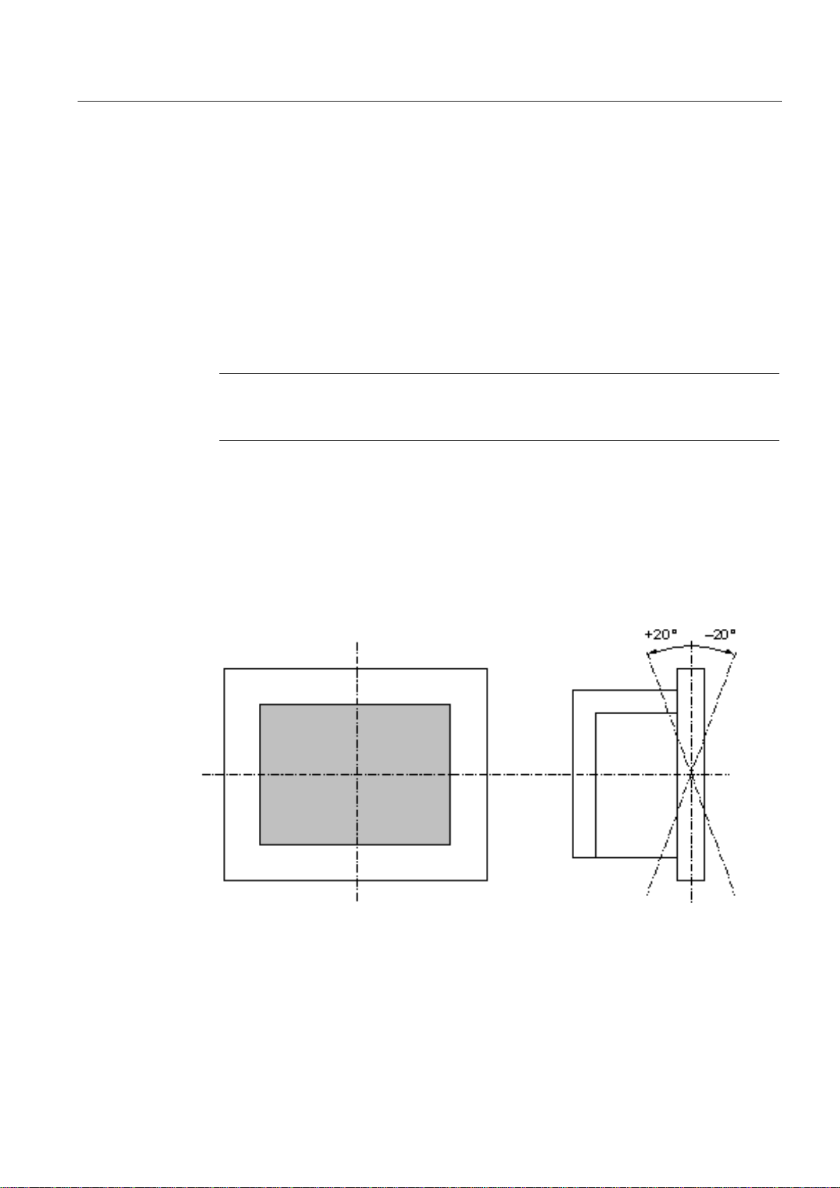
Approval
Certain installation positions are approved for the device.
Figure 3-3 Approved installation positions for central design
Vertical installation and deviations between +20° and -20° in the given directions is
permitted.
SIMATIC PC Panel PC 677/877, Control Unit
Operating Instructions, Edition 04/2005, A5E00407724-01
3-5

Application planning
3.6 Mounting cut-out
3.5.3 Type of fixation
The computer unit is secured in the installation cut-out either with clamps or screws.
Notice
Securing with screws is not possible with the 12" touch screen variant. For more information,
please refer to the chapter "Description."
Select the method of attachment suitable to your requirements for the degree of protection.
3.5.4 Degree of protection
Principle
The degree of protection provided by the front side can only be guaranteed when the
mounting seal lies completely against the mounting cut-out.
Degree of protection IP65 and Nema 4
Caution
Please ensure that the material strength at the mounting cut-out is a maximum of 6 mm.
Please follow the specifications for the dimensions in the "Mounting cut-out" section.
The degrees of protection are only guaranteed when the following is observed:
• The material strength at the mounting cut-out is at least 2 mm.
• The deviation of the evenness of the mounting cut-out for installed control units relating to the
outside dimensions of the control unit is ≤ 0.5 mm.
The degree of protection IP65 and Nema 4 are only guaranteed when clamps are secured
together with an encircling seal.
IP54 degree of protection
This degree of protection is provided for screw mounting.
3.6 3.6 Mounting cut-out
3.6.1 Select and complete recessed mounting cut-out
Requirements
The degree of protection suitable to the field of application and thereby the method of
attachment have been selected.
Procedure
1. Please follow the installation guidelines.
2. Select a location suitable for installation, taking into account the installation guidelines
and the chosen installation position.
3. On the basis of the dimension diagrams, check whether the required screw and pressure
points on the backside and the hatched seal area are easily accessible after the
completion of the installation cut-out. Otherwise the installation cut-out is useless.
4. Complete the installation cut-out according to the dimension diagrams.
SIMATIC PC Panel PC 677/877, Control Unit
3-6 Operating Instructions, Edition 04/2005, A5E00407724-01
Application planning
3.6 Mounting cut-out
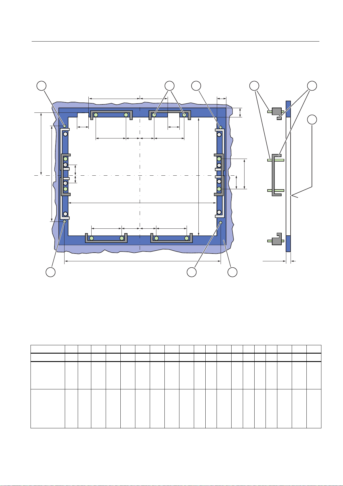
3.6.2 Dimensions
The following illustrations show the dimensions for the installation cut-out.
/
/ /
/ 6 6 /
/
66
/
/ 6 6 /
/
/
/
$
$
/
6
/
$
Figure 3-4 Drill holes for the screws and pressure points for the clamp screws
1 Drill hole for screw attachment
2 Pressure point for clamp
3 setscrews
4 Clamp
5 R
6 Seal area
Table 3-1 Measurements for the mounting cut-out in mm
Control units L1 L2 L3
Tolerance +1 +1 ±0.2 ±0.2 ±0.5 ±0.5 ±0.5 ±0.5 +1 ±1 ±1 ±1 ±1 ±1 ±1 ±1 ±1 ±1
key panels
12" TFT
15" TFT
Touch
screen front
12" TFT
15" TFT
19" TFT
450
450
368
450
450
290
326
290
290
380
120 in the seal area
Z
1)
1)
L4
L5 L6
112
235
465
112
279
465
112
—
—
112
235
465
112
235
465
—
186
—
—
—
2)
L7
—
135
—
—
—
2)
L8
—
25
—
—
—
2)
L9
2)
A1 A2 A3 S1 S2 S3 S4 S53) S63) S73)
—
165
—
—
—
16
16
16
16
16
10
17
10
10
10
1.5
min
to 6
max
1.5
min.
to 6
max
78
51
19
81
46
78
51
35
81
46
78
51
35
81
46
78
51
35
81
46
56
56
56
56
—
—
—
—
—
33
—
—
—
—
33
SIMATIC PC Panel PC 677/877, Control Unit
Operating Instructions, Edition 04/2005, A5E00407724-01
3-7

Application planning
3.6 Mounting cut-out
1) M6 thread or drill hole with a diameter of 7 mm
2) Cut-outs for the shafts of the insert strip are only necessary for 15" key panels.
3) Only for 19" touch panel fronts are two clamps necessary for vertically securing clamps.
More information about device dimensions, e.g. mounting depth, can be found in the
"Dimensional Drawings" section.
SIMATIC PC Panel PC 677/877, Control Unit
3-8 Operating Instructions, Edition 04/2005, A5E00407724-01
Installation
4.1 4.1 Securing with clamps
Range of validity
Skip this step if you have selected "screw mounting."
Requirements
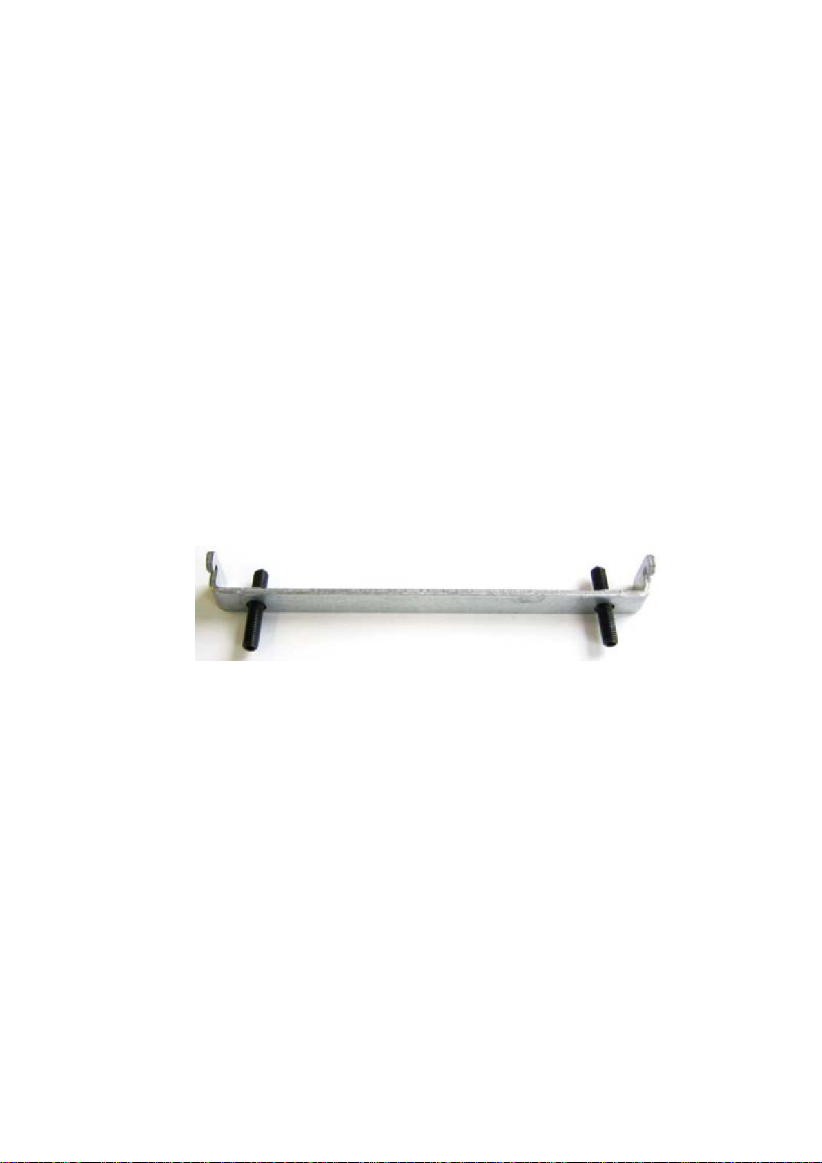
• The installation cut-out has been completed.
• Clamps are readily available in the accessories. Clamp and grub screws are included in
the contents of delivery.
Figure 4-1 Clamp assembly
4
Procedure
1. Follow the installation guidelines.
2. Working from the front, insert the device into the installation cut-out.
3. Secure the control unit in the installation cut-out from behind with the clamps, as shown in
the installation cut-out in the dimension diagrams. Tighten the grub screw to a torque of
0.4-0.5 Nm.
SIMATIC PC Panel PC 677/877, Control Unit
Operating Instructions, Edition 04/2005, A5E00407724-01
4-1
Installation
4.2 Securing with screws
4.2 4.2 Securing with screws
Range of validity
Skip this step if you have selected "clamp mounting."
Requirements
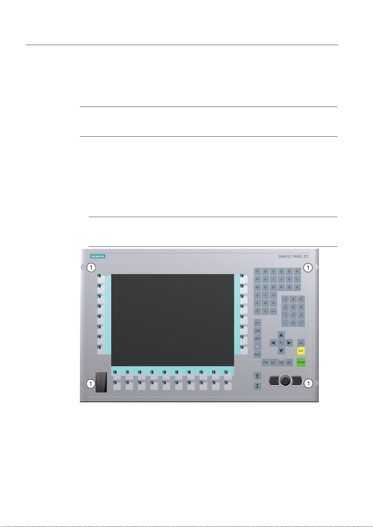
Procedure
Notice
You cannot use screws to secure the device with the 12" touch screen variant. For more
information, please refer to the chapter "Description."
The installation cut-out has been completed.
1. Follow the installation guidelines.
2. Drill suitable holes at the prepared installation cut-out in accordance with the
specifications for L4 and L5, as shown in the installation cut-out in the dimension
diagrams.
3. Carefully drill the respective holes in the control unit at the designed location (1) from the
rear.
Caution
Ensure that no metal cuttings enter the device. Cover the device with film or when drilling,
use removal by suction.
Figure 4-2 Designated location for holes on the control unit
4. Working from the front, insert the device into the installation cut-out.
5. Secure the control unit by inserting suitable screws through the holes and attaching nuts.
4.3 4.3 Dimensions
The mounting depth increases by 21 mm when an optical drive is installed in the device.
Take the dimensions from the dimensional drawings.
SIMATIC PC Panel PC 677/877, Control Unit
4-2 Operating Instructions, Edition 04/2005, A5E00407724-01

Connecting
5.1 5.1 Front ports
Introduction
A USB port is located on the front side. For more information, please refer to the chapter
"Operation." Attach an external keyboard or an external mouse, for example, to the USB
port. The front-sided USB port supports the standard USB 2.0.
Caution
Wait at least 10 seconds between the unplugging and replugging of USB devices. This also
applies in particular to touch control in control units with touch screen panels.
Notice
When the cover over the USB port is opened in order to connect a USB component, the
degree of protection for the device is no longer guaranteed.
When using standard USB peripherals, please bear in mind that their EMC immunity level is
frequently designed for office applications only. These device may be used for
commissioning and servicing. However, only industry-standard devices are allowed for
industrial operation.
5
The USB peripherals are developed and marketed by individual vendors. The respective
manufacturers offer support for the peripherals. Moreover, the terms of liability of the
individual vendors or suppliers apply here.
5.2 5.2 Other interfaces
Other Connections
SIMATIC PC Panel PC 677/877, Control Unit
Operating Instructions, Edition 04/2005, A5E00407724-01
Caution
Please comply with the connections in the computer unit operating instructions.
5-1
 Loading...