

Page 1

Preface
Overview
1
SIMATIC HMI
HMI device
TP 270, OP 270, MP 270B
(WinCC flexible)
Operating Instructions
Safety notes and general
information
Plan deployment
Installation and connection
Operating elements and
indicators
Operating system and
configuration
Prepare and backup project
Runtime functionalities of a
project
2
3
4
5
6
7
8
Order number 6AV6691-1DD01-0AB0
Operate project
Operating recipes
Maintenance/Service
Technical data
Appendix
Abbreviations
Glossary
9
10
11
12
A
B
C
Edition 03/2004
A5E00280664-01
Page 2
이 기기는 업무용(A급) 전자파 적합기기로서 판매자 또는 사용자는 이 점을 주의하시기 바라며 가정 외의 지역에서 사용하는 것을 목적으로 합니다.
Safety Guidelines
This manual contains notices which you should observe to ensure your own personal safety as well as to avoid
property damage. The notices referring to your personal safety are highlighted in the manual by a safety alert
symbol, notices referring to property damage only have no safety alert symbol.
Danger
indicates an imminently hazardous situation which, if not avoided, will result in death or serious injury.
Warning
indicates a potentially hazardous situation which, if not avoided, could result in death or serious injury.
Caution
used with the safety alert symbol indicates a potentially hazardous situation which, if not avoided, may
result in minor or moderate injury.
Caution
used without safety alert symbol indicates a potentially hazardous situation which, if not avoided, may
result in property damage.
Notice
used without the safety alert symbol indicates a potential situation which, if not avoided, may result in
an undesirable result or state.
When several danger levels apply, the notices of the highest level (lower number) are always displayed. If a
notice refers to personal damages with the safety alert symbol, then another notice may be added warning of
property damage.
Qualified Personnel
The device/system may only be set up and operated in conjunction with this documentation. Only qualified
personnel should be allowed to install and work on the equipment. Qualified persons are defined as persons who
are authorized to commission, to earth, and to tag circuits, equipment and systems in accordance with
established safety practices and standards.
Intended Use
Please note the following:
Warning
This device and its components may only be used for the applications described in the catalog or
technical description, and only in connection with devices or components from other manufacturers
approved or recommended by Siemens.
This product can only function correctly and safely if it is transported, stored, set up and installed
correctly, and operated and maintained as recommended.
Trademarks
All designations marked with ® are registered trademarks of Siemens AG. Other designations in this
documentation might be trademarks which, if used by third parties for their purposes, might infringe upon the
rights of the proprietors.
Copyright Siemens AG, 2004. All rights reserved
Reproduction, transmission or use of this document or its contents is not permitted without
express written authority. Offenders will be liable for damages. All rights, including rights
created by patent grant or registration of a utility model or design, are reserved.
Siemens AG
Automation and Drives Group
P.O. Box 4848, D-90327 Nuremberg (Germany)
Siemens Aktiengesellschaft 6AV6691-1DD01-0AB0
Disclaimer of Liability
We have checked the contents of this manual for agreement with the hardware and
software described. Since deviations cannot be precluded entirely, we cannot guarantee
full agreement. However, the data in the manual are reviewed regularly, and any
necessary corrections will be included in subsequent editions. Suggestions for
improvement are welcomed.
© Siemens AG 2004
Technical data subject to change
Page 3

Preface
Purpose of the manual
This manual provides the required information and documentation for machine construction
in compliance with DIN 8418. The information contained relates to the device, its installation
site, transport, storage, use and maintenance.
The manual is aimed at the following target groups:
• Users
• Commissioners
• Service technicians
• Maintenance engineers
Read carefully the Chapter "Safety and General Information".
The help integrated in WinCC flexible, namely the WinCC flexible Information System,
contains further information. The Information System provides instructions, examples and
references in electronic form.
Basic knowledge required
A general knowledge of automation technology and process communication is necessary in
order to understand the manual.
It is assumed users have good basic knowledge in the use of personal computers and MS
Windows operating systems.
Manual application
The manual applies to the SIMATIC MP 270B, OP 270 and TP 270 in connection with the
WinCC flexible 2004 software packet.
Modifications compared to previous release 12/2001
The manual describes the use of the HMI devices together with WinCC flexible 2004. For
implementation with WinCC flexible 2004, the MP 270B 6" device model is also available.
The previous version, 12/2001, can still be used on the HMI device with ProTool.
Position in the information scheme
This manual is part of the SIMATIC HMI documentation. The information below presents an
overview of the information scheme of SIMATIC HMI.
TP 270, OP 270, MP 270B (WinCC flexible)
Operating Instructions, Edition 03/2004, 6AV6691-1DD01-0AB0
i
Page 4

Preface
User manual
• WinCC flexible Micro:
– Describes basic configuration principles using the WinCC flexible Micro Engineering
System
• WinCC flexible Compact/Standard/Advanced:
– Describes basic configuration principles using the WinCC flexible Compact
Engineering System/WinCC flexible Standard/WinCC flexible Advanced
• WinCC flexible Runtime:
– Describes commissioning and operating the runtime project on a PC.
• WinCC flexible Migration:
– Describes how to convert an existing ProTool project to WinCC flexible.
– Describes how to convert an existing WinCC project to WinCC flexible.
– Describes the conversion of ProTool projects together with changing the HMI device
from OP7 to OP 77B.
– Describes the conversion of ProTool projects together with changing the graphic HMI
devices to Windows CE devices.
• Communication
– Communication Part 1 describes the connection of the HMI device to SIMATIC PLCs.
– Communication Part 2 describes the connection of the HMI device to third-party PLCs.
Operating instructions
• Operating instructions for HMI devices SIMATIC OP 77B,
TP 170micro/TP 170A/TP 170B/OP 170B, SIMATIC Mobile Panel 170, SIMATIC
TP 270/OP 270/MP 270B, SIMATIC MP 370.
• Quick reference manuals for the SIMATIC OP 77B and SIMATIC Mobile Panel 170 HMI
devices.
Getting started
• WinCC flexible for beginners:
– Provides step-by-step instructions on the principles of configuring screens, alarms,
recipes and screen navigation using an project example.
• WinCC flexible for advanced users:
– Provides step-by-step instructions on the principles of configuring logs, project reports,
scripts, user administration, multilingual projects and integration in STEP 7 using an
project example.
• WinCC flexible Options:
– Provides step-by-step instructions on the principles of configuring the options
WinCC flexible Sm@rtServices, Sm@rtAccess and OPC-Server using an project
example.
TP 270, OP 270, MP 270B (WinCC flexible)
ii Operating Instructions, Edition 03/2004, 6AV6691-1DD01-0AB0
Page 5

Preface
Online availability
The following links provide direct access to technical documentation on SIMATIC products
and systems in English, German, French, Italian and Spanish:
• SIMATIC Guide Technical Documentation in German:
http://www.ad.siemens.de/simatic/portal/html_00/techdoku.htm
• SIMATIC Guide for Technical Documentation in English:
http://www.ad.siemens.de/simatic/portal/html_76/techdoku.htm
Conventions
A distinction has been made in the naming of the configuration and runtime software:
• "WinCC flexible" refers to the configuration software.
• "Runtime" refers to the runtime software capable of running on the HMI devices.
Generally, the term "WinCC flexible" is used. The version identification, e.g.
"WinCC flexible 2004", is always used when it is necessary to make a version distinction.
The following text highlights are intended to simplify reading the manual:
Display method Application
"Add screens"
"File > Edit" Operation sequences, e.g. menu commands, pop-up menu commands.
<F1>, <Alt+P> Keyboard input
• Terms which appear on the user interface, e.g. dialog names, tabs,
buttons, menu commands.
• Required input, e.g. limit vales, tag values.
• Path information
Trademarks
Also observe the information identified as follows:
Note
Notes contain important information about the product or operation of the product. Notes
also refer to areas within the documentation which require special attention.
All names identified by ® are registered trademarks of the Siemens AG.
HMI®
SIMATIC®
SIMATIC HMI®
SIMATIC ProTool®
SIMATIC WinCC®
SIMATIC WinCC flexible®
SIMATIC MP 270B®
SIMATIC OP 270®
SIMATIC TP 270®
The remaining trademarks in this publication may be trademarks whose use by third parties
for their own purposes could violate the rights of the owner.
TP 270, OP 270, MP 270B (WinCC flexible)
Operating Instructions, Edition 03/2004, 6AV6691-1DD01-0AB0
iii
Page 6

Preface
Representatives and agents
If you have any further queries regarding products described in the manual, please contact
the Siemens representatives or agents responsible for your area.
Contact partners can be located under:
http://www.siemens.com/automation/partner
Training center
We offer relevant courses to simplify your introduction to the world of automation systems.
Please contact your regional training center or our central training center in D 90327
Nuernberg, Germany for details.
Phone: +49 (911) 895-3200.
Internet: http://www.sitrain.com
Service & Support on the Internet
Service & Support provides comprehensive, additional information on SIMATIC products
through online services at "http://www.siemens.com/automation/service&support":
• The Newsletter, containing the latest information on your products.
• Numerous documents are available by searching through Service & Support.
• A forum, in which users and specialists can exchange experiences.
• The latest product information, FAQs and downloads.
• Contact partners for Automation & Drives are listed in the contact partner database.
• Information on on-site services, repairs, spare parts and much more under the term
"Services".
TP 270, OP 270, MP 270B (WinCC flexible)
iv Operating Instructions, Edition 03/2004, 6AV6691-1DD01-0AB0
Page 7

Preface
A&D Technical Support
Available round the clock, worldwide:
Worldwide (Nuremberg)
Technical Support
(Free Contact)
Local time: Mon.-Fri. 7:00 to 17:00.
Phone: +49 (0) 180 5050-222
Fax: +49 (0) 180 5050-223
E-mail: adsupport@siemens.com
GMT: +1:00
Europe/Africa (Nuremberg)
Authorization
Local time: Mon.-Fri. 7:00 to 17:00.
Phone: +49 (911) 895-7200
Fax: +49 (911) 895-7201
E-mail:
adauthorisierung@siemens.com
GMT: +1:00
Johnson City
Worldwide (Nuremberg)
Technical Support
(fee-based, only with SIMATIC Card)
Local time: 0:00 to 24:00, 365 days a year
Phone: +49 (911) 895-7777
Fax: +49 (911) 895-7001
GMT: +1:00
United States (Johnson City)
Technical Support and Authorization
Local time: Mon.-Fri. 8:00 to 19:00.
Phone: +1 423 461-2522
Fax: +1 423 461-2289
E-mail:
simatic.hotline@sea.siemens.com
GMT: -5:00
Nuremberg
SIMATIC Hotline
Beijing
Asia/Australia (Beijing)
Technical Support and Authorization
Local time: Mon.-Fri. 08:30 to 5:30 pm.
Phone: +86 10 64 75 75 75
Fax: +86 10 64 74 74 74
E-mail:
adsupport.asia@siemens.com
GMT: +8:00
Information is available in English and German.
TP 270, OP 270, MP 270B (WinCC flexible)
Operating Instructions, Edition 03/2004, 6AV6691-1DD01-0AB0
v
Page 8

Preface
TP 270, OP 270, MP 270B (WinCC flexible)
vi Operating Instructions, Edition 03/2004, 6AV6691-1DD01-0AB0
Page 9

Table of contents
Preface ........................................................................................................................................................i
1 Overview................................................................................................................................................. 1-1
1.1 Introduction ................................................................................................................................ 1-1
1.2 Field of Application..................................................................................................................... 1-2
1.3 Configuring with WinCC flexible................................................................................................. 1-3
1.4 Features..................................................................................................................................... 1-4
1.5 Functional scope........................................................................................................................ 1-7
1.6 Communication with PLCs....................................................................................................... 1-11
1.7 Options..................................................................................................................................... 1-12
1.7.1 Hardware options..................................................................................................................... 1-12
1.7.1.1 Backup battery ......................................................................................................................... 1-12
1.7.1.2 PC card / CF card .................................................................................................................... 1-14
1.7.2 Software options ...................................................................................................................... 1-16
1.7.2.1 Internet Explorer ...................................................................................................................... 1-16
2 Safety notes and general information ..................................................................................................... 2-1
2.1 Safety notes ............................................................................................................................... 2-1
2.2 General information ................................................................................................................... 2-1
3 Plan deployment..................................................................................................................................... 3-1
3.1 Transport.................................................................................................................................... 3-1
3.2 Installation notes ........................................................................................................................ 3-2
3.3 Installation locations and type of protection...............................................................................3-3
3.4 Producing the installation cut-out............................................................................................... 3-4
4 Installation and connection ..................................................................................................................... 4-1
4.1 Check shipment ......................................................................................................................... 4-1
4.2 Installation of the HMI device..................................................................................................... 4-1
4.2.1 Installing the MP 270B Keys or OP 270 .................................................................................... 4-1
4.2.2 Installing the MP 270B Touch or TP 270 10"............................................................................. 4-3
4.3 Connecting the HMI device........................................................................................................ 4-5
4.3.1 Conditions .................................................................................................................................. 4-5
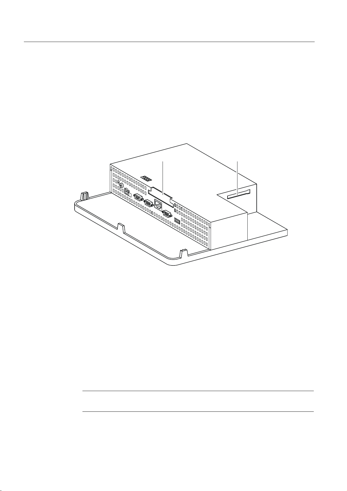
4.3.2 Interfaces ................................................................................................................................... 4-6
4.3.3 Connecting the potential equalization........................................................................................ 4-8
4.3.4 Connecting peripheral equipment..........................................................................................
4.3.4.1 Connect print
4.3.4.2 Connect external keyboard and mouse ................................................................................... 4-12
4.3.5 Connecting the PLC................................................................................................................. 4-13
4.3.6 Connecting the configuration computer ................................................................................... 4-15
4.3.7 Connecting an uninterruptible power supply (UPS)................................................................. 4-16
er.........................................................................................................................
.. 4-10
4-10
TP 270, OP 270, MP 270B (WinCC flexible)
Operating Instructions, Edition 03/2004, 6AV6691-1DD01-0AB0
vii
Page 10

Table of contents
4.3.8 Connecting the power supply................................................................................................... 4-17
4.4 Switch on and test the HMI device........................................................................................... 4-18
5 Operating elements and indicators ......................................................................................................... 5-1
5.1 MP 270B Touch and TP 270...................................................................................................... 5-1
5.2 MP 270B Keys and OP 270 ....................................................................................................... 5-2
5.2.1 Key pads .................................................................................................................................... 5-2
5.2.2 Function keys ............................................................................................................................. 5-5
5.2.3 System keys............................................................................................................................... 5-6
5.2.4 Labeling the softkeys ................................................................................................................. 5-8
5.3 Operation with external keyboard/mouse ................................................................................ 5-12
6 Operating system and configuration ....................................................................................................... 6-1
6.1 HMI device loader ...................................................................................................................... 6-1
6.2 Windows CE Control Panel........................................................................................................ 6-2
6.2.1 Open Control Panel.................................................................................................................... 6-2
6.2.2 Communication .......................................................................................................................... 6-5
6.2.3 Date/time.................................................................................................................................... 6-5
6.2.4 InputPanel .................................................................................................................................. 6-6
6.2.5 Network ...................................................................................................................................... 6-6
6.2.6 OP .............................................................................................................................................. 6-7
6.2.7 Printer....................................................................................................................................... 6-11
6.2.8 Regional Settings..................................................................................................................... 6-13
6.2.9 Screensaver ............................................................................................................................. 6-14
6.2.10 System ..................................................................................................................................... 6-15
6.2.11 UPS.......................................................................................................................................... 6-16
6.2.12 Volume & Sounds .................................................................................................................... 6-17
6.3 Network operation .................................................................................................................... 6-18
6.3.1 Basic principles ........................................................................................................................ 6-18
6.3.2 Configuring the HMI device for network operation................................................................... 6-19
6.3.3 Test network............................................................................................................................. 6-21
6.3.4 Configuring network access..................................................................................................... 6-22
7 Prepare and backup project.................................................................................................................... 7-1
7.1 Transfer project to the HMI device............................................................................................. 7-1
7.1.1 Commissioning for the first time.........................................................................................
7.1.2 Rec
ommiss
ioning....................................................................................................................... 7-3
........ 7-1
7.2 Transfer...................................................................................................................................... 7-3
7.2.1 Start transfer manually............................................................................................................... 7-3
7.2.2 Start transfer automatically ........................................................................................................ 7-4
7.2.3 Transfer mode options ............................................................................................................... 7-5
7.2.4 Test project ................................................................................................................................ 7-8
7.2.5 Uploading project ..................................................................................................................... 7-10
7.3 System settings........................................................................................................................ 7-12
7.3.1 Set language ............................................................................................................................ 7-12
7.3.2 Set operating mode.................................................................................................................. 7-13
7.4 Other transfer functions............................................................................................................ 7-14
7.4.1 Functions.................................................................................................................................. 7-14
7.4.2 Backup and Restore................................................................................................................. 7-15
7.4.3 Update operating system ......................................................................................................... 7-18
7.4.4 Transferring authorizations ...................................................................................................... 7-21
7.4.5 Transferring options ................................................................................................................. 7-22
TP 270, OP 270, MP 270B (WinCC flexible)
viii Operating Instructions, Edition 03/2004, 6AV6691-1DD01-0AB0
Page 11

Table of contents
8 Runtime functionalities of a project ......................................................................................................... 8-1
8.1 Screen objects ........................................................................................................................... 8-1
8.2 Alarms ........................................................................................................................................ 8-2
8.3 Tags ........................................................................................................................................... 8-3
8.4 Logs ........................................................................................................................................... 8-3
8.5 Reports....................................................................................................................................... 8-5
8.6 System functions and scripts ..................................................................................................... 8-6
8.7 Safety ......................................................................................................................................... 8-7
8.8 Other operating functions........................................................................................................... 8-9
9 Operate project....................................................................................................................................... 9-1
9.1 Basic principles of operation ...................................................................................................... 9-1
9.1.1 Basics for operation in runtime .................................................................................................. 9-1
9.1.2 Operating the touch panel.......................................................................................................... 9-3
9.1.2.1 Operating touch objects ............................................................................................................. 9-3
9.1.2.2 Input of values............................................................................................................................ 9-5
9.1.2.3 Input of numeric values.............................................................................................................. 9-5
9.1.2.4 Input of alphanumeric values..................................................................................................... 9-8
9.1.2.5 Calling the operator note.......................................................................................................... 9-10
9.1.3 Operating a keyboard device ................................................................................................... 9-11
9.1.3.1 Functions of the system keys................................................................................................... 9-11
9.1.3.2 Functions of the key combinations........................................................................................... 9-12
9.1.3.3 Input of values.......................................................................................................................... 9-15
9.1.3.4 Calling the operator note.......................................................................................................... 9-15
9.2 Controlling graphic objects....................................................................................................... 9-16
9.2.1 Button....................................................................................................................................... 9-16
9.2.1.1 Description ............................................................................................................................... 9-16
9.2.1.2 Touch control ........................................................................................................................... 9-17
9.2.1.3 Keyboard control...................................................................................................................... 9-17
9.2.1.4 Mouse and keyboard control.................................................................................................... 9-18
9.2.2 Switch....................................................................................................................................... 9-18
9.2.2.1 Description ............................................................................................................................... 9-18
9.2.2.2 Touch control ........................................................................................................................... 9-19
9.2.2.3 Keyboard control...................................................................................................................... 9-19
9.2.2.4 Mouse and keyboard control.............................................................................................
9.2.3 I/O field
9.2.3.1 Des
..................................................................................................................................... 9-20
cription ............................................................................................................................... 9-20
....... 9-19
9.2.3.2 Touch control ........................................................................................................................... 9-20
9.2.3.3 Keyboard control...................................................................................................................... 9-21
9.2.3.4 Mouse and keyboard control.................................................................................................... 9-21
9.2.4 Graphic I/O field ....................................................................................................................... 9-22
9.2.4.1 Description ............................................................................................................................... 9-22
9.2.4.2 Touch control ........................................................................................................................... 9-22
9.2.4.3 Keyboard control...................................................................................................................... 9-23
9.2.4.4 Mouse and keyboard control.................................................................................................... 9-23
9.2.5 Symbolic I/O field ..................................................................................................................... 9-24
9.2.5.1 Description ............................................................................................................................... 9-24
9.2.5.2 Touch control ........................................................................................................................... 9-24
9.2.5.3 Keyboard control...................................................................................................................... 9-25
9.2.5.4 Mouse and keyboard control.................................................................................................... 9-25
9.2.6 Alarm indicator ......................................................................................................................... 9-26
9.2.6.1 Description ............................................................................................................................... 9-26
TP 270, OP 270, MP 270B (WinCC flexible)
Operating Instructions, Edition 03/2004, 6AV6691-1DD01-0AB0
ix
Page 12

Table of contents
9.2.6.2 Touch control ........................................................................................................................... 9-26
9.2.6.3 Mouse control........................................................................................................................... 9-27
9.2.7 Alarm view................................................................................................................................ 9-27
9.2.7.1 Description ............................................................................................................................... 9-27
9.2.7.2 Touch control ........................................................................................................................... 9-28
9.2.7.3 Keyboard control ...................................................................................................................... 9-29
9.2.7.4 Mouse and keyboard control.................................................................................................... 9-29
9.2.8 Simple alarm view .................................................................................................................... 9-30
9.2.8.1 Description ............................................................................................................................... 9-30
9.2.8.2 Touch control ........................................................................................................................... 9-31
9.2.8.3 Keyboard control ...................................................................................................................... 9-31
9.2.8.4 Mouse and keyboard control.................................................................................................... 9-31
9.2.9 Recipe view.............................................................................................................................. 9-32
9.2.9.1 Description ............................................................................................................................... 9-32
9.2.9.2 Touch control ........................................................................................................................... 9-33
9.2.9.3 Keyboard control ...................................................................................................................... 9-33
9.2.9.4 Mouse and keyboard control.................................................................................................... 9-34
9.2.10 Simple recipe view ................................................................................................................... 9-35
9.2.10.1 Description ............................................................................................................................... 9-35
9.2.10.2 Touch control ........................................................................................................................... 9-36
9.2.10.3 Keyboard control ...................................................................................................................... 9-36
9.2.10.4 Mouse and keyboard control.................................................................................................... 9-37
9.2.11 Bar............................................................................................................................................ 9-38
9.2.12 Trend view................................................................................................................................ 9-39
9.2.12.1 Description ............................................................................................................................... 9-39
9.2.12.2 Touch control ........................................................................................................................... 9-40
9.2.12.3 Keyboard control ...................................................................................................................... 9-41
9.2.12.4 Mouse and keyboard control.................................................................................................... 9-41
9.2.13 Slider control ............................................................................................................................ 9-42
9.2.13.1 Description ............................................................................................................................... 9-42
9.2.13.2 Touch control ........................................................................................................................... 9-43
9.2.13.3 Keyboard control ...................................................................................................................... 9-43
9.2.13.4 Mouse and keyboard control............................................................................................
9.2.14 Gauge.......................................................................................................................................
9.2.15 Date/time field ..........................................................................................................................
........ 9-44
9-44
9-45
9.2.15.1 Description ............................................................................................................................... 9-45
9.2.15.2 Touch control ........................................................................................................................... 9-45
9.2.15.3 Keyboard control ...................................................................................................................... 9-46
9.2.15.4 Mouse and keyboard control.................................................................................................... 9-46
9.2.16 Clock ........................................................................................................................................ 9-47
9.2.17 User view ................................................................................................................................. 9-48
9.2.17.1 Description ............................................................................................................................... 9-48
9.2.17.2 Touch control ........................................................................................................................... 9-49
9.2.17.3 Keyboard control ...................................................................................................................... 9-49
9.2.17.4 Mouse and keyboard control.................................................................................................... 9-49
9.2.18 Simple user view ...................................................................................................................... 9-50
9.2.18.1 Description ............................................................................................................................... 9-50
9.2.18.2 Touch control ........................................................................................................................... 9-50
9.2.18.3 Keyboard control ...................................................................................................................... 9-50
9.2.18.4 Mouse and keyboard control.................................................................................................... 9-51
9.2.19 Status/Force............................................................................................................................. 9-52
9.2.19.1 Description ............................................................................................................................... 9-52
9.2.19.2 Touch control ........................................................................................................................... 9-53
9.2.19.3 Keyboard control ...................................................................................................................... 9-53
9.2.19.4 Mouse and keyboard control.................................................................................................... 9-54
9.2.20 Sm@rtClient view..................................................................................................................... 9-55
9.2.20.1 Description ............................................................................................................................... 9-55
TP 270, OP 270, MP 270B (WinCC flexible)
x Operating Instructions, Edition 03/2004, 6AV6691-1DD01-0AB0
Page 13

Table of contents
9.2.20.2 Touch control ........................................................................................................................... 9-57
9.2.20.3 Keyboard control...................................................................................................................... 9-57
9.2.20.4 Mouse and keyboard control.................................................................................................... 9-58
9.2.21 Symbol library .......................................................................................................................... 9-58
9.2.21.1 Description ............................................................................................................................... 9-58
9.2.21.2 Touch control ........................................................................................................................... 9-59
9.2.21.3 Mouse control........................................................................................................................... 9-59
10 Operating recipes ................................................................................................................................. 10-1
10.1 Recipes .................................................................................................................................... 10-1
10.2 Structure of recipes.................................................................................................................. 10-3
10.3 Structure of recipe data records............................................................................................... 10-4
10.4 Recipe application.................................................................................................................... 10-5
10.4.1 Transfer of recipe data records................................................................................................ 10-5
10.4.2 Configuration of recipes ........................................................................................................... 10-6
10.4.3 Scenario: Entering recipe data records in Runtime ................................................................. 10-8
10.4.4 Scenario: Manual production sequence ................................................................................ 10-10
10.4.5 Scenario: Automatic production sequence ............................................................................ 10-12
10.5 Displaying recipes.................................................................................................................. 10-13
10.5.1 Viewing and editing recipes in Runtime................................................................................. 10-13
10.5.2 Behavior of the recipe view in Runtime ................................................................................. 10-15
10.6 Recipe data record administration ......................................................................................... 10-15
10.6.1 Recipe data record administration ......................................................................................... 10-15
10.6.2 Synchronizing a recipe data record ....................................................................................... 10-17
10.6.3 Read recipe data record from PLC ........................................................................................ 10-18
10.6.4 Transfer recipe record to PLC................................................................................................ 10-18
10.6.5 Exporting and importing recipe data records ......................................................................... 10-19
10.6.6 Reactions to modifications of the recipe structure ................................................................. 10-20
10.7 Example ................................................................................................................................. 10-21
10.7.1 Example: Creating a recipe.................................................................................................... 10-21
10.7.2 Example: Configuring a recipe screen................................................................................... 10-23
11 Maintenance/Service ............................................................................................................................ 11-1
11.1 Clean screen/keyboard foil ................................................................................................
11.1.1 General information
11.1.2
Notes on the touch panel ......................................................................................................... 11-2
................................................................................................................. 11-1
...... 11-1
11.2 Replacing the optional backup battery..................................................................................... 11-3
12 Technical data ...................................................................................................................................... 12-1
12.1 Dimension drawings................................................................................................................. 12-1
12.1.1 MP 270B 10" Touch, TP 270 10" dimensions.......................................................................... 12-1
12.1.2 MP 270B 6" Touch, TP 270 6" dimensions.............................................................................. 12-2
12.1.3 Dimensions, MP 270B 10" Keys, OP 270 10" ......................................................................... 12-3
12.1.4 Dimensions, OP 270 6"............................................................................................................ 12-4
12.2 Technical data.......................................................................................................................... 12-5
12.3 EMC requirements ................................................................................................................... 12-8
12.4 Interfaces ................................................................................................................................. 12-9
TP 270, OP 270, MP 270B (WinCC flexible)
Operating Instructions, Edition 03/2004, 6AV6691-1DD01-0AB0
xi
Page 14

Table of contents
A Appendix.................................................................................................................................................A-1
A.1 Certificates and Directives .........................................................................................................A-1
A.1.1 Approvals ...................................................................................................................................A-1
A.1.2 ESD guidelines...........................................................................................................................A-2
A.2 System alarms ...........................................................................................................................A-3
B Abbreviations..........................................................................................................................................B-1
B.1 Abbreviations .............................................................................................................................B-1
C Glossary .................................................................................................................................................C-1
Index
Tables
Table 1-1
Table 1-2 Communication with PLCs from other manufacturers ............................................................. 1-11
Table 12-1 9-pin Sub-D plug (pin).............................................................................................................. 12-9
Table 12-2 9-pin Sub-D socket (configuration via switch).......................................................................... 12-9
Table 12-3 9-pin Sub-D plug (pin)............................................................................................................ 12-10
Table 12-4 RJ45 plug connection............................................................................................................. 12-10
Table 12-5 USB standard plug................................................................................................................. 12-11
Communication with SIMATIC PLCs ....................................................................................... 1-11
TP 270, OP 270, MP 270B (WinCC flexible)
xii Operating Instructions, Edition 03/2004, 6AV6691-1DD01-0AB0
Page 15

Overview
1.1 Introduction
HMI devices in the middle performance range
The Multi Panel MP 270B, Touch Panel TP 270 and Operator Panel OP 270 extend the
product spectrum in the middle performance range.
The HMI devices are based on the innovative standard operating system, Microsoft Windows
CE. The robustness and speed of the dedicated hardware solutions are combined with the
flexibility of the PC world.
The MP 270B represents the "Multifunctional Platform" product category and is distinguished
by its variable deployment. This product category is positioned in the product hierarchy
between the process-related, optimized application components, such as operator panels
and controllers, and industrial PCs.
The panels TP 270 and OP 270 are downgraded models and less expensive, but still provide
convincing functionality
The comprehensive product range allows users to choose the HMI device most suited to
their needs. All HMI devices include the following advantages:
1
• High degree of configuration efficiency
• Configuration simulation on the configuration computer - no PLC required
• Clear display and easy process operation using a Window-Based user interface
• Large selection of predefined screen objects for use during configuration
• Dynamic screen objects, e.g. moving objects
• Uncomplicated and quick handling of recipes and data records in recipe screens and
recipe views
• Logging of alarms, process values and login/logout procedures
• Creation of vector graphics using the WinCC flexible configuration software without an
external graphics editor,
• Transfer:
– Automatic switchover to transfer mode
– Transfer via MPI, PROFIBUS DP, USB and Ethernet
– Serial transfer
– Transfer via TeleService
• Standard connections to SIMATIC S5/DP, SIMATIC S7 and SIMATIC 505, as well as to
PLCs from other manufacturers
TP 270, OP 270, MP 270B (WinCC flexible)
Operating Instructions, Edition 03/2004, 6AV6691-1DD01-0AB0
1-1
Page 16

Overview
1.2 Field of Application
Position in the SIMATIC HMI environment
The HMI devices were designed for the middle performance range. They meet the demands
placed on performance, display possibilities and price/performance ratio. In addition, they
extend the communication potential of the office world. Customer needs and requests were
taken into account in respect to extending data transfer functions, simplifying operation, and
increasing acceptance when compared with Windows CE units.
The HMI devices not only support the classic HMI applications (visualization with WinCC
flexible) but also additional applications, such as process diagnostics (ProAgent).
1.2 Field of Application
Overview
The HMI device allows graphic display of operating statuses, current process data and errors
of connected PLCs. The user can operate and observe the machine or system being
monitored easily using the HMI device.
Applicable areas of use include machine and apparatus construction sectors, printing and
packing industries, automobile and electrical industries and chemical and pharmaceutical
industries.
The high degree of protection (IP65 on the front side) and avoidance of moving storage
media, such as hard disks and floppy disks, ensure that the HMI device is suitable for use in
rough industrial environments and on site where a machine is located.
Possible installation locations for the HMI device:
• Switching cabinets/consoles
• 19" cabinets/racks (keyboard units)
Connection options for external peripherals (keyboard, mouse and printer) via a USB port,
for example, and the possible use of CF and PC cards support multifunctionality. Due to the
fact that the HMI device is equipped with high performance basic hardware and has a
minimum installation depth means that it fulfills all the requirements for operation in the
vicinity of the machine.
The HMI device can be used to:
• Operate and monitor the process using the menu system. Setpoint values or control
element settings can be modified by entering values or activating configured softkeys
• Display processes, machines and systems on full-graphic, dynamic screens
• Display and process alarms and tags through output fields, bar graphs or trend curves
• Use input to intervene directly in the running process
TP 270, OP 270, MP 270B (WinCC flexible)
1-2 Operating Instructions, Edition 03/2004, 6AV6691-1DD01-0AB0
Page 17
Overview
1.3 Configuring with WinCC flexible
1.3 Configuring with WinCC flexible
Introduction
In order to operate a machine or system using an HMI device, the user interface must be
configured for the HMI device. This procedure is referred to as the "configuration phase".
PC/PU
Create project data
Configuration phase
Save project data
Test the configuration
Simulate configuration
Principle
Operating unit
PLC
Process running phase
Figure 1-1 Configuration and process running phases
Download project data
Connected to PLC
1. Configuring the functionality of the user interface. This includes the following:
– Graphics
– Text
– Customized functions
– Operating and indicator objects
Use a configuration computer (PC or PU) with the WinCC flexible configuration software.
2. Connect the configuration computer to the HMI device.
The following connection options are available:
– Serial
– MPI/PROFIBUS DP
– USB or Ethernet interface
– Standard modem path
3. Transfer the configuration to the HMI device.
4. Connect the HMI device to the PLC.
TP 270, OP 270, MP 270B (WinCC flexible)
Operating Instructions, Edition 03/2004, 6AV6691-1DD01-0AB0
1-3
Page 18
Overview
1.4 Features
Result
The HMI device communicates with the PLC and responds to the program progress in the
PLC ("process running phase") according to the information configured.
1.4 Features
Overview of MP 270B 10", OP 270 10" and TP 270 10"
Features MP 270B 10" Keys MP 270B 10"
Touch
Processor Type RISC CPU
Memory for
configuration
Software Operating system Microsoft Windows CE
Interfaces Interfaces for
Color display
Membrane
keyboard
Capacity (max.) 4 MB 2 MB
• 2 x RS 232, 1 x RS 422, 1 x RS 485
connecting PLC,
PC/PU, printer,
network, external
mouse and
keyboard
Type TFT LCD TFT LCD with
Active screen
diagonals
Resolution (pixels) 640 x 480
Possible colors 256
Back-lighting CCFL tubes
System keys with
dedicated
functions
Softkeys with
configurable
functions
Those for local
assignment
Softkey labeling With labeling strips - With labeling strips -
• 1 x PC card slot
• 1 x CF card slot
• 1 x USB
• 1 x Ethernet (RJ45)
touch panel
38 (3 with LEDs) - 38 (3 with LEDs) -
36 (28 with LEDs) - 36 (28 with LEDs) -
20 (12 with LEDs) - 20 (12 with LEDs) -
OP 270 10" TP 270 10"
• 2 x RS 232, 1 x RS 422, 1 x RS 485
• 1 x CF card slot
• 1 x USB
STN LCD STN LCD with
10,4 "
touch panel
TP 270, OP 270, MP 270B (WinCC flexible)
1-4 Operating Instructions, Edition 03/2004, 6AV6691-1DD01-0AB0
Page 19
Overview
1.4 Features
Features MP 270B 10" Keys MP 270B 10"
Touch
Acoustic
acknowledgement
Special features
In the case of
touch control
DP direct keys
(touch buttons as
I/O periphery)
DP direct keys
(keys as I/O
periphery)
External memory
extension for
recipes, logs and
alarms etc.
Slot for PC card x x - -
Slot for CF card x x x x
- x - x
- x - x
x - x -
x x x x
Overview of MP 270B 6" Touch, OP 270 6" and TP 270 6"
OP 270 10" TP 270 10"
Features MP 270B 6" Touch OP 270 6" TP 270 6"
Processor Type RISC CPU
Memory for
configuration
Software Operating system Microsoft Windows CE
Interfaces Interfaces for
Color display
TP 270, OP 270, MP 270B (WinCC flexible)
Operating Instructions, Edition 03/2004, 6AV6691-1DD01-0AB0
Capacity (max.) 4 MB 2 MB
• 2 x RS 232, 1 x RS
connecting PLC,
PC/PU, printer,
network, external
mouse and keyboard
Type TFT LCD with touch
Active screen diagonal 5,7 "
Resolution (pixels) 320 x 240
Possible colors 256
Back-lighting CCFL tubes
422, 1 x RS 485
• 1 x PC card slot
• 1 x CF card slot
• 1 x USB
• 1 x Ethernet
(RJ45)
panel
• 2 x RS 232, 1 x RS 422, 1 x RS 485
• 1 x CF card slot
• 1 x USB
CSTN LCD CSTN LCD with touch
panel
1-5
Page 20

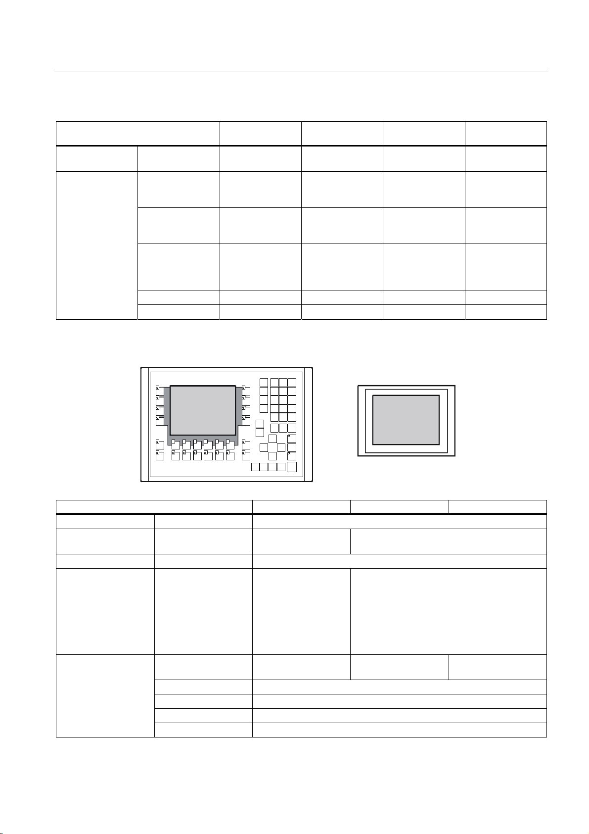
Overview
1.4 Features
Features MP 270B 6" Touch OP 270 6" TP 270 6"
Membrane keyboard
Acoustic
acknowledgement
Special features
System keys with
dedicated functions
Softkeys with
configurable functions
Those for local
assignment
Softkey labeling - System-specific with
In the case of touch
control
DP direct keys (touch
buttons as I/O
periphery)
DP direct keys (keys
as I/O periphery)
External memory
extension for recipes,
logs and alarms etc.
Slot for PC card x -
Slot for CF card x x
- 36 (3 with LEDs) -
- 24 (18 with LEDs) -
- 14 (8 with LEDs) -
-
labeling strips
x - x
x - x
- x -
x x
Further information
The creation of projects for HMI devices and functions for the configuration software is
described in detail in the "WinCC flexible" user manual and in the WinCC online help.
Information on connecting the HMI device to the PLC is provided in the "WinCC flexible
Communication" user manual.
The "Readme.chm" file on the WinCC flexible CD contains the most current information
which could not be included in the manuals and online help due to time constraints.
TP 270, OP 270, MP 270B (WinCC flexible)
1-6 Operating Instructions, Edition 03/2004, 6AV6691-1DD01-0AB0
Page 21
Overview
1.5 Functional scope
1.5 Functional scope
General information
The following table summarizes the range of functions provided by the HMI device. The
numeric values are maximum values which the HMI device is capable of managing. These
values are not cumulative. It is not possible to simultaneously configure 4000 alarms and
300 screens each with 400 tags per screen.
The defined values are also limited by the size of the configuration memory.
Function MP 270B Keys MP 270B
Touch
Alarms
ALARM_S Display S7 alarms x
Alarm logging Output to printer x
Volatile alarm buffer
Number 4000
Discrete alarms Yes
Analog alarms Yes
Indicators Alarm line/Alarm window/alarm view
Process values in alarm
text
Length of the alarm text 80 characters (dependent on font)
Color-coding of different
alarm states
Warning alarms x
Error alarms
Type of display
Acknowledge individual
alarms
Acknowledge several
error alarms
simultaneously (group
acknowledgement)
Alarm buffer capacity 512 alarm events, circular buffer
View alarms x
Delete x
Print x
Time of occurrence Date/time Alarm acquisition
Alarm events Arrived, departed, acknowledged
First/last, selectable
16 acknowledgment groups
OP 270 TP 270
8
x
x
x
TP 270, OP 270, MP 270B (WinCC flexible)
Operating Instructions, Edition 03/2004, 6AV6691-1DD01-0AB0
1-7
Page 22
Overview
1.5 Functional scope
Function MP 270B Keys MP 270B
Touch
Screens
Tags Number 2048
Limit value monitoring Input/output x
Conversion functions Input/output x
Number 500
Text objects 10000 text elements
Fields per screen 200
Tags per screen 200
Operating elements
Operator prompting
Help text
Animation
Unhide/hide objects
Softkey icons
Tab order
LEDs in softkeys
Fixed window x
• Button
• Switch
• I/O field
• Graphic I/O field
• Symbolic I/O field
• Alarm indicator
• Alarm view
• Alarm window
• Recipe view
• Bar
• Trend view
• Slider control
• Gauge
• Date / time field
• Clock
• User view
• Status force
• Sm@rtClient view
• Symbol library
x
x
x
x
x
x
x
x
x
-
-
-
OP 270 TP 270
x
x
x
x
x
x
1)
x
x
x
-
-
-
TP 270, OP 270, MP 270B (WinCC flexible)
1-8 Operating Instructions, Edition 03/2004, 6AV6691-1DD01-0AB0
Page 23

Overview
1.5 Functional scope
Help text
Logging
Lists
Print functions
Safety
Recipes
force)
Function MP 270B Keys MP 270B
Touch
Lines/characters 7/35 (dependent on font)
For alarms x
For screens x
For screen objects
I/O field
Symbolic I/O field
Graphic I/O field
Button
Switch
Hidden button
x
x
x
x
x
x
x
x
x
-
-
-
Alarms x
Tags x
Log type Circular/sequential log
Number of logs 20
Number of tags for
logging
Number of sequential
logs
Entries per log 500000, limited by storage medium
Memory location
• PC card
• CF card
• Ethernet
Number 500
Graphics lists 400
Text lists 500
Hardcopy of the screen
content, also in color
Direct alarm logging x
Freely configurable logs x
Number of user groups 50
No. of users 50
No. of authorizations 32
Number 300
Data records per recipe 500, limited by storage medium
Elements per recipe 1000
Recipe memory 64 KB (integr. Flash, expandable)
Number of languages 5 Online languages
Project languages (with
system alarms)
Chinese (simplified), Chinese (traditional), Czechoslovakian,
Danish, Dutch, English, Finnish, French, German, Greek,
Hungarian, Italian, Japanese, Korean, Norwegian, Polish,
Portuguese, Russian, Spanish, Swedish, Turkish
SIMATIC S5 x PU functions (status
SIMATIC S7 x
OP 270 TP 270
x
x
x
x
x
x
20
400
• CF card
• Ethernet (optional)
x
2)
x
x
x
-
-
-
2)
TP 270, OP 270, MP 270B (WinCC flexible)
Operating Instructions, Edition 03/2004, 6AV6691-1DD01-0AB0
1-9
Page 24

Overview
1.5 Functional scope
Function MP 270B Keys MP 270B
Touch
Scheduler Trigger functions
cyclically or once
User-specific expansions
of functionality
Number of scripts 50
Connections 3) Number 6
OP 270 TP 270
x
x VBScript
1) Maximum total number for PowerTags and internal tags
2) Storage media refers to PC cards, CF cards and network drives
3) With SIMATIC S7
TP 270, OP 270, MP 270B (WinCC flexible)
1-10 Operating Instructions, Edition 03/2004, 6AV6691-1DD01-0AB0
Page 25

Overview
1.6 Communication with PLCs
1.6 Communication with PLCs
The following tables list the PLCs which can be connected to the HMI device.
Table 1-1 Communication with SIMATIC PLCs
PLC MP 270B Keys MP 270B Touch OP 270 TP 270
SIMATIC S5 AS511 1)
SIMATIC S5 DP
SIMATIC S7–200 x
SIMATIC S7–300/400 x
SIMATIC 500/505 serial
SIMATIC 500/505 DP
SIMATIC HMI HTTP Protocol x
OPC 2) x -
SIMATIC WinAC x
SIMOTION x
x
x
x
x
1) Only via converter cable
2) Data exchange only via XML (connection to OPC-XML server)
Table 1-2 Communication with PLCs from other manufacturers
PLC MP 270B Keys MP 270B Touch OP 270 10"/OP 270
6"
Allen Bradley DF1
Allen Bradley DH485
LG GLOFA-GM x
Modicon MODBUS x
Mitsubishi FX
Mitsubishi Protocol 4
GE Fanuc SNP x
Omron Hostlink/Multilink x
x
x
x
x
TP 270 10"/TP 270
6"
TP 270, OP 270, MP 270B (WinCC flexible)
Operating Instructions, Edition 03/2004, 6AV6691-1DD01-0AB0
1-11
Page 26
Overview
1.7 Options
1.7 Options
1.7.1 Hardware options
1.7.1.1 Backup battery
Function of the backup battery
The battery ensures that in the event of a power failure, the HMI device's internal hardware
clock continues to run. If no battery is available, the clock continues for approx. three days
as long as the HMI device was in operation for 6 to 8 hours, without interruption, beforehand.
The battery is not supplied with the HMI device.
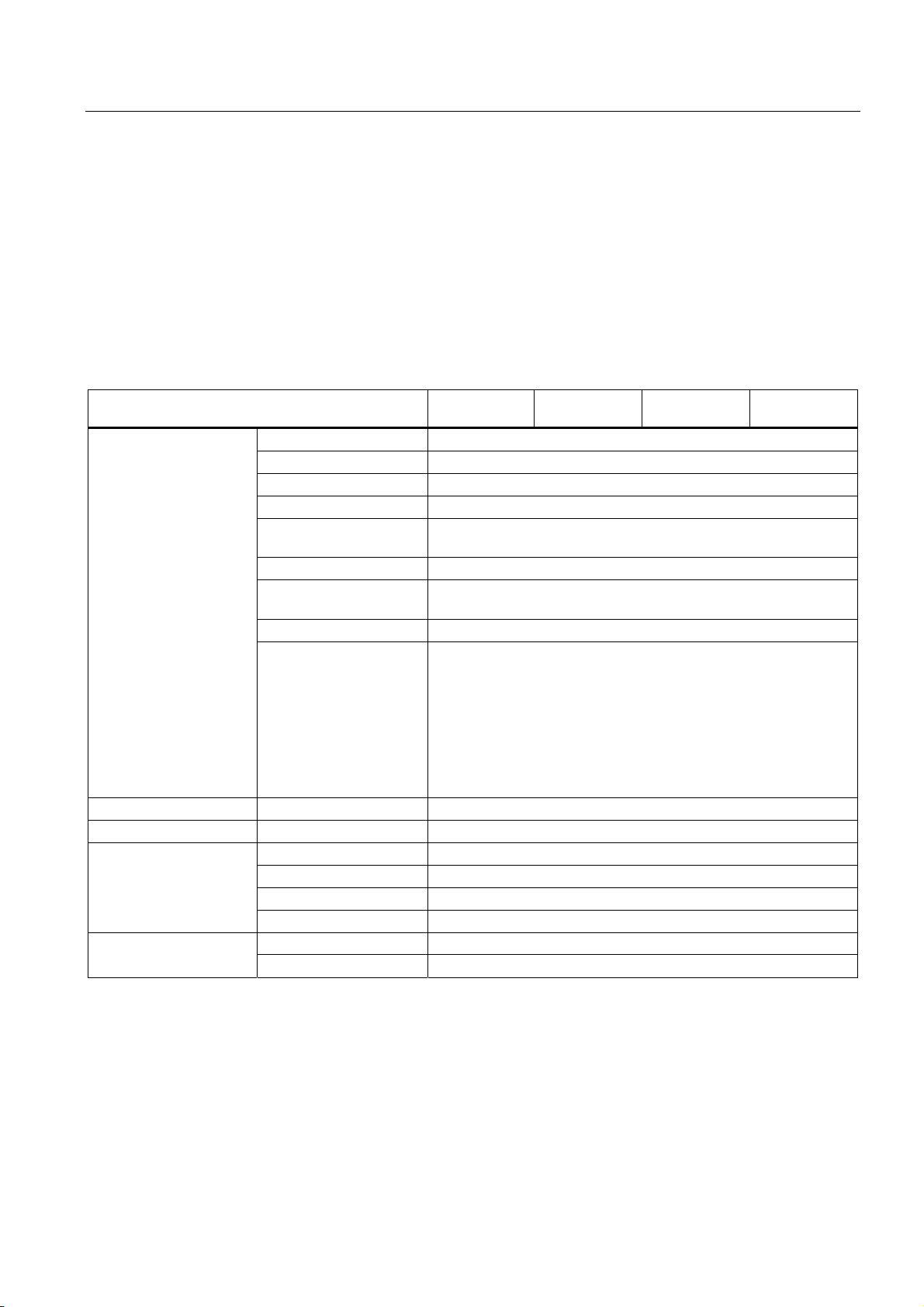
Installation in the MP 270B 10", TP 270 10" or OP 270 10"
1. Secure the battery with two cable ties to the back of the HMI device. The position is
indicated by an arrow in the following figures.
Figure 1-2 MP 270B 10" Keys / OP 270 10"
Figure 1-3 MP 270B 10" Touch / TP 270 10"
2. Insert the battery lead connector into the two-pin socket. The plug is coded to prevent
reversed poling.
TP 270, OP 270, MP 270B (WinCC flexible)
1-12 Operating Instructions, Edition 03/2004, 6AV6691-1DD01-0AB0
Page 27
Overview
1.7 Options
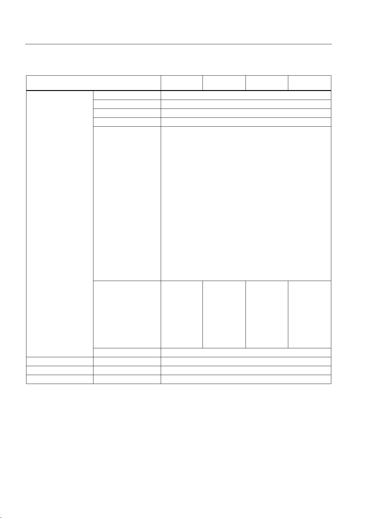
Assembly on MP 270B 6" Touch, TP 270 6" and OP 270 6"
1. Secure the battery to the back of the HMI device with one cable tie. The position is
indicated by an arrow in the following figures.
Figure 1-4 OP 270 6"
Figure 1-5 MP 270B 6" Touch / TP 270 6"
See also
2. Insert the battery lead connector into the two-pin socket. The plug is coded to prevent
reversed poling.
Replacing the optional backup battery (Page 11-3)
Interfaces (Page 4-6)
TP 270, OP 270, MP 270B (WinCC flexible)
Operating Instructions, Edition 03/2004, 6AV6691-1DD01-0AB0
1-13
Page 28
Overview
1.7 Options
1.7.1.2 PC card / CF card
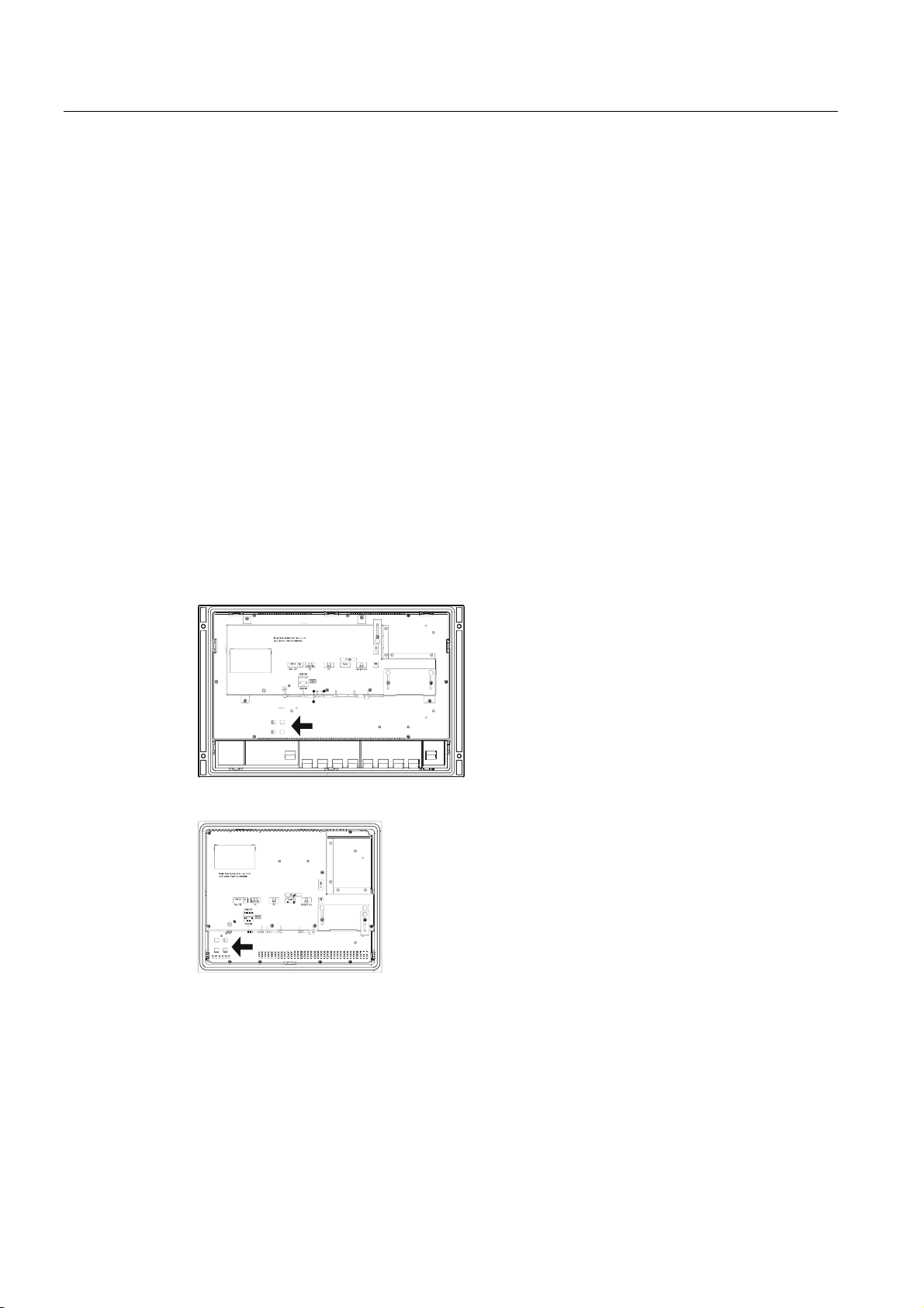
Purpose
Changeable PC cards and CF cards can be inserted in the two slots, Slot A and Slot B on
the back of the MP 270B. They are not supplied.
The TP 270 and OP 270 have only one slot for CF cards (Slot B).
Changeable memory cards can be used, for example, to store important process data or
execute a backup/restore of the internal flash memory.
Slot A Slot B
Cards supported
Figure 1-6 Position of the slots (example of MP 270B 10" Keys)
The HMI device supports standard cards which operate with a programming voltage of 5 V:
• Slot A (PC card) (type I and II) (for MP 270B only):
– ATA Flash card
– SRAM card
– NE2000-compatible Ethernet card
• Slot B (CF card) (type I):
– ATA Flash card
– NE2000-compatible Ethernet card
Caution
The current limitation is 300 mA per slot.
TP 270, OP 270, MP 270B (WinCC flexible)
1-14 Operating Instructions, Edition 03/2004, 6AV6691-1DD01-0AB0
Page 29

Overview
1.7 Options
Remove memory card
Caution
Ensure that the HMI device does not access the memory card during the removal process.
Otherwise, the contents of the memory card will be fully destroyed.
1. Terminate access made by the HMI device to the memory card.
If the configuration engineer has defined an operating element linked to the
"CloseAllLogs" system function, press the element. Otherwise, press the operating
element linked to the "StopRuntime" system function in the configuration. This ends
runtime.
2. Wait unit the HMI device displays the loader.
Changeover to the loader may take several minutes depending on the size and number
of logs stored.
3. Remove the memory card.
Switch off the HMI device with memory card inserted
Caution
Always terminate the runtime software before switching off the voltage supply in order to
prevent loss of data.
1. Terminate runtime.
Press the operating element linked to the "StopRuntime" system function in the
configuration.
2. Wait unit the HMI device displays the loader.
Changeover to the loader may take several minutes depending on the size and number
of logs stored.
3. Switch off the power supply.
If the power supply is interrupted during normal operation, the HMI device checks the
memory card after power is restored and repairs any defect sectors.
See also
HMI device loader (Page 6-1)
TP 270, OP 270, MP 270B (WinCC flexible)
Operating Instructions, Edition 03/2004, 6AV6691-1DD01-0AB0
1-15
Page 30

Overview
1.7 Options
1.7.2 Software options
1.7.2.1 Internet Explorer
Overview
The Internet Explorer supplied with the HMI device has been specially adapted to the
Windows CE operating system and has a restricted functional scope (Pocket Internet
Explorer). Only simple HTML pages, about 100 kb, can be displayed.
Prior to installation, use the system settings to set 1.5 Mb memory for the DRAM file system.
Caution
If too much memory is provided for the DRAM file system, runtime has too little working
memory available. Therefore, in the case of incorrect settings, there is no guarantee that the
runtime can run properly.
Caution
The operation of runtime together with the Internet Explorer can only be guaranteed when
the run-capable configuration (*.fwx) generated is a maximum of 2 Mb.
The installation of Internet Explorer is performed using the ProSave service tool or WinCC
flexible configuration software.
Files created in Internet Explorer, e.g. Favorites, are stored in the DRAM file system. The
DRAM file system is deleted when the unit is switched off. However, using the system
settings (OP Properties > Persistent Storage > Save Files), it is possible to backup the data
currently available in the DRAM file system to the Flash memory. When the device is started
up, the backup data is automatically restored.
If you remove the Internet Explorer, the files created from Internet Explorer must also be
deleted. To do this, delete the files in the DRAM file system using the standard Explorer.
Then backup the DRAM file system ("OP Properties > Persistent Storage > Save Files").
Reset the size of the DRAM file system to the preset value of 2 Mb.
Note
The initial configuration can be restored simply by updating the operating system.
See also
System (Page 6-15)
Update operating system (Page 7-18)
Transferring options (Page 7-22)
TP 270, OP 270, MP 270B (WinCC flexible)
1-16 Operating Instructions, Edition 03/2004, 6AV6691-1DD01-0AB0
Page 31

Safety notes and general information
2.1 Safety notes
Work on the cabinet
Warning
Danger, high voltage
Opening the cabinet will expose high voltage parts. Contact with these parts could be fatal.
Switch off the power supply to the cabinet before opening it.
High frequency radiation
2
Notice
Exceptional operating situations
High-frequency emissions, e.g. from cell phones, can cause exceptional operating situations.
2.2 General information
Use in industrial areas
The HMI device is designed for use in industrial environments. It complies with the following
standards and norms:
• Requirements concerning interference immunity EN 61000-6-4: 2001
• Requirements related to interference immunity EN 61000-6-2: 2001
TP 270, OP 270, MP 270B (WinCC flexible)
Operating Instructions, Edition 03/2004, 6AV6691-1DD01-0AB0
2-1
Page 32

Safety notes and general information
2.2 General information
Use in residential areas
If the HMI device is used in a residential area, the measures related to limiting the emission
of radio interference Class B complying to EN 55011 must be met.
Appropriate measures to limit the emission of Class B radio interference include the
following:
• Installation of the HMI device in a grounded cabinet
• Use of filters in electrical supply lines
TP 270, OP 270, MP 270B (WinCC flexible)
2-2 Operating Instructions, Edition 03/2004, 6AV6691-1DD01-0AB0
Page 33

Plan deployment
3.1 Transport
Only unpack the HMI device at its location of use.
Notice
When transporting the HMI device in low temperature areas or areas with extreme
temperature fluctuations, ensure that no condensation develops.
The HMI device must be at room temperature before startup. Do not attempt to warm the
device using direct heat. If condensation should occur, only switch on the HMI device after
waiting approximately 4 hours.
Problem-free, reliable operation of the HMI device requires proper transport, storage,
positioning and assembly as well as careful operation and maintenance.
Failure to meet these requirements voids the rights to claims under the terms of warranty.
3
TP 270, OP 270, MP 270B (WinCC flexible)
Operating Instructions, Edition 03/2004, 6AV6691-1DD01-0AB0
Notice
The HMI device was function-tested before shipping. If a fault occurs nevertheless, please
enclose a full account of the fault when returning the device.
3-1
Page 34

Plan deployment
3.2 Installation notes
3.2 Installation notes
Electromagnetic compatibility
The HMI device fulfills the requirements requirements as stipulated by German law on EMC
as well as the EMC guidelines of the European Union.
Installation in grounded metal cabinets, e.g. 8 MC cabinet complying to Siemens catalog
NV21, ensures compliance to EN 61000-4-2.
Installing HMI devices to conform to EMC requirements
A PLC design which is compliant with EMC requirements and uses interference-proof cables
is required for error-free operation. The "Guidelines for Interference-Free Construction of
PLCs" and the "PROFIBUS network Manual" are installation references for the HMI device.
Caution
Only shielded cables are permitted for all signal connections.
Screw or lock all plug connections.
Do not install signal lines in the same cable ducts as power cables.
Siemens AG refuses to accept liability for malfunctions and damage arising from use of selfmade cables or cables from other manufacturers.
Conditions for use
The HMI device is intended for installation in weatherproof, permanent locations. The
conditions for the use of the HMI device exceed the requirements as outlined in DIN IEC
60721-3-3 in the following classes:
• Class 3M3 (mechanical requirements)
• Class 3K3 (climatic requirements)
Use with additional measures
The HMI device may not be used in the following circumstances without implementation of
additional measures:
• In locations with a high degree of ionizing radiation
• In locations with extreme operating conditions resulting from situations such as the
following:
– corrosive vapors or gases
– strong electrostatic or magnetic fields
TP 270, OP 270, MP 270B (WinCC flexible)
3-2 Operating Instructions, Edition 03/2004, 6AV6691-1DD01-0AB0
Page 35

Plan deployment
3.3 Installation locations and type of protection
• In systems which require special monitoring facilities. For example:
– elevator systems
– in particularly hazardous locations
The HMI device may be installed in a cabinet as an additional measure.
See also
EMC requirements (Page 12-8)
3.3 Installation locations and type of protection
Installation location
The HMI device is designed for installation in the front panels of cabinets and consoles. The
MP 270B 10" Keys and OP 270 10" are also designed for installation in 19" cabinets and
racks.
Cut an installation cut-out in a front panel. The thickness of the front panel must not exceed
6 mm. Additional holes for securing the HMI device are not necessary because a clamping
mechanism is available.
Degree of protection
Install the HMI device Install the HMI device to meet the minimum requirements for IP54
degree of protection. The IP65 degree of protection for the front panel can only be ensured
when the seal on the front plate of the HMI device is fitted correctly.
Notice
The NEMA 4 or IP65 degrees of protection are only ensured when
- in the case of MP 270B 6", OP 270 6" or TP 270 6", the plate thickness of the installation
support is at least 2 mm
- in the case of MP 270B 10", OP 270 10" or TP 270 10", the plate thickness of the
installation support is at least 2.5 mm
Caution
The systems ability to be waterproof and dustproof as per the section "Approvals" is only
guaranteed when the following is met:
• Material thickness of installation cut-out: 2 to 6 mm (MP 270B 6", OP 270 6" or TP 270 6") and 2.5
• Deviation of the installation cut-out from the horizontal related to the overall dimensions of the HMI
• Permissible surface roughness in the area of the seal: max. 120 µm (R
to 6 mm (MP 270B 10", OP 270 10" or TP 270 10")
device: = 0.5 mm
120)
z
TP 270, OP 270, MP 270B (WinCC flexible)
Operating Instructions, Edition 03/2004, 6AV6691-1DD01-0AB0
3-3
Page 36

Plan deployment
3.4 Producing the installation cut-out
Ambient conditions
Caution
If the maximum permissible ambient temperature is exceeded, do not operate the HMI
device without external ventilation.
Otherwise, the HMI device may be damaged and the approvals listed in the Section
"Approvals" and the terms of warranty are void.
See also
Approvals (Page A-1)
Technical data (Page 12-5)
3.4 Producing the installation cut-out
Select position for the installation cut-out
Caution
To prevent the HMI device from overheating during operation:
- The angle of inclination from vertical installation may not exceed a maximum of ±35°
- Do not expose the operating unit to direct sunlight
- Ensure that the ventilation slits in the housing are not obstructed
TP 270, OP 270, MP 270B (WinCC flexible)
3-4 Operating Instructions, Edition 03/2004, 6AV6691-1DD01-0AB0
Page 37

Plan deployment
3.4 Producing the installation cut-out
Installation cut-out
MP 270B 10" Touch, TP 270 10"
Notice
The following air flow requirements must be maintained following installation:
- 100 mm above the HMI device
- 50 mm below the HMI device
- 15 mm at the sides of the HMI device
When using plug-in boards, ensure sufficient space is provided to insert or remove them.
For installation in a front panel, the MP 270B 10" Touch or TP 270 10" requires an
installation cut-out (WxH) of 310
not exceed 6 mm.
MP 270B 6" Touch, TP 270 6"
Notice
The following air flow requirements must be maintained following installation:
- 150 mm above the HMI device
- 100 mm below the HMI device
+1
mm x 248 +1 mm. The thickness of the front panel must
- 15 mm at the sides of the HMI device
When using plug-in boards, ensure sufficient space is provided to insert or remove them.
For installation in a front panel, the MP 270B 6" Touch or TP 270 6" requires an installation
cut-out (WxH) of 198
mm.
TP 270, OP 270, MP 270B (WinCC flexible)
Operating Instructions, Edition 03/2004, 6AV6691-1DD01-0AB0
+1
mm x 142 +1 mm. The thickness of the front panel must not exceed 6
3-5
Page 38

Plan deployment
3.4 Producing the installation cut-out
MP 270B 10" Keys, OP 270 10"
OP 270 6"
Notice
The following air flow requirements must be maintained following installation:
-50 mm above the HMI device
-15 mm below the HMI device
- 15 mm at the sides of the HMI device
When using plug-in boards, ensure sufficient space is provided to insert or remove them.
For installation in a front panel, the MP 270B 10" Keys or TP 270 10" requires an installation
cut-out (WxH) of 436
mm.
Notice
The following air flow requirements must be maintained following installation:
- 100 mm above the HMI device
- 50 mm below the HMI device
+1
mm x 295 +1 mm. The thickness of the front panel must not exceed 6
- 15 mm at the sides of the HMI device
When using plug-in boards, ensure sufficient space is provided to insert or remove them.
For installation in a front panel, the OP 270 6" requires an installation cut-out (WxH) of 282 +1
mm x 178
+1
mm. The thickness of the front panel must not exceed 6 mm.
TP 270, OP 270, MP 270B (WinCC flexible)
3-6 Operating Instructions, Edition 03/2004, 6AV6691-1DD01-0AB0
Page 39

Installation and connection
4.1 Check shipment
Inventory the contents of the shipment. Check for visible signs of damage which may have
occurred during shipment.
4.2 Installation of the HMI device
Notice
Do not install damaged parts. If parts are damaged, contact ...
Keep the documentation supplied. This belongs to the HMI device and may be required
when commissioning in the future.
4
4.2.1 Installing the MP 270B Keys or OP 270
Prior to installation
If you want to change the labels on the softkeys, change the labeling strips before installing
the HMI device.
Installation in 19” cabinets/racks
Refer to the information provided by the respective cabinet or rack manufacturer to install the
device in a 19” cabinet/rack.
Installation dimensions of standard 19” cabinets:
• Width: 19" (482.6 mm)
• Height: 7 HE (310 mm)
Secure the HMI device to the rails using four screws
TP 270, OP 270, MP 270B (WinCC flexible)
Operating Instructions, Edition 03/2004, 6AV6691-1DD01-0AB0
4-1
Page 40
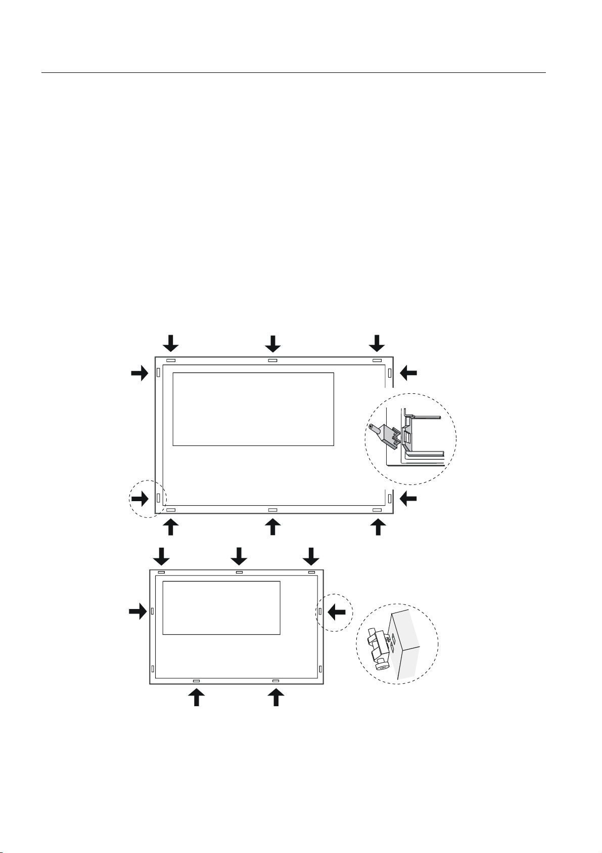
Installation and connection
4.2 Installation of the HMI device
Installation in front panels
The MP 270B Keys and OP 270 can be secured in the installation cut-out using spring
terminals. When secured using spring terminals, no additional holes for securing the device
are required in the front panel.
Spring terminals used in conjunction with an outer seal can achieve IP65 degree of
protection. Screwed supports achieve the degree of protection IP54.
Installing the MP 270B Keys or OP 270 in the front panel:
1. Check that the installation seal is fitted on the HMI device.
Do not mount the installation seal turned inside out. This can lead to gaps in the
installation cut-out.
2. Working from the front, insert the HMI device into the installation cut-out.
3. Insert the hooks of the spring terminals into the corresponding recesses in the housing of
the HMI device.
The individual positions are indicated in the figures below by means of arrows.
MP 270B Key, OP 270 10”
OP 270 6”
If necessary, the OP 270 6" can be additionally held by two further spring terminals
inserted in the two bottom recesses on the side of the HMI device. They are not supplied
with the OP 270 6" .
TP 270, OP 270, MP 270B (WinCC flexible)
4-2 Operating Instructions, Edition 03/2004, 6AV6691-1DD01-0AB0
Page 41

Installation and connection
4.2 Installation of the HMI device
4. Working from the back, secure the MP 270B 10" Keys or OP 270 10" into the front panel
using an Allen wrench. Use a Phillips screwdriver for the OP 270 6".
Caution
Check the fit of the rubber seal on the front side. It must not protrude from the HMI
device.
Over tightening the screws will damage the HMI device.
See also
Installation locations and type of protection (Page 3-3)
Dimensions, OP 270 6" (Page 12-4)
Labeling the softkeys (Page 5-8)
Dimensions, MP 270B 10" Keys, OP 270 10" (Page 12-3)
4.2.2 Installing the MP 270B Touch or TP 270 10"
Installation in front panels
The MP 270B Touch and TP 270 can be secured in the installation cut-out using spring
terminals. When secured using spring terminals, no additional holes for securing the device
are required in the front panel.
Spring terminals used in conjunction with an outer seal can achieve IP65 degree of
protection. Screwed supports achieve the degree of protection IP54.
Installing the MP 270B Touch or TP 270 in the front panel:
1. Check that the installation seal is fitted on the HMI device.
Do not mount the installation seal turned inside out. This can lead to gaps in the
installation cut-out.
2. Working from the front, insert the HMI device into the installation cut-out.
TP 270, OP 270, MP 270B (WinCC flexible)
Operating Instructions, Edition 03/2004, 6AV6691-1DD01-0AB0
4-3
Page 42

Installation and connection
4.2 Installation of the HMI device
3. Insert the hooks of the spring terminals into the corresponding recesses in the housing of
the HMI device.
The individual positions are indicated in the figures below by means of arrows.
1
MP 270B 10" Touch,
TP 270 10”
1
MP 270B 6" Touch,
TP 270 6”
1 Front panel
4. Working from the back, secure the MP 270B 10" Touch or TP 270 10" in the front panel
using an Allen wrench. Use a Phillips screwdriver for the MP 270B 6" Touch and TP 270
6".
Caution
Check the fit of the rubber seal on the front side. It must not protrude from the HMI
device.
Over tightening the screws will damage the HMI device.
See also
MP 270B 10" Touch, TP 270 10" dimensions (Page 12-1)
MP 270B 6" Touch, TP 270 6" dimensions (Page 12-2)
TP 270, OP 270, MP 270B (WinCC flexible)
4-4 Operating Instructions, Edition 03/2004, 6AV6691-1DD01-0AB0
Page 43

Installation and connection
4.3 Connecting the HMI device
4.3 Connecting the HMI device
4.3.1 Conditions
Requirements
The following condition must be fulfilled before the HMI device is connected electrically:
• The HMI device must be installed according to the information provided in these
operating instructions.
Electrical connections
Connect the HMI device in the following sequence:
1. Potential equalization line
2. PLC
3. Configuration computer as necessary
4. Peripheral equipment as necessary
5. Power supply
Notice
Connection sequence
Carefully follow the sequence of HMI device connections. Failure to do so may result in
damage to the HMI device.
When disconnecting the connections, it is essential to proceed in the reverse sequence.
TP 270, OP 270, MP 270B (WinCC flexible)
Operating Instructions, Edition 03/2004, 6AV6691-1DD01-0AB0
4-5
Page 44

Installation and connection
4.3 Connecting the HMI device
4.3.2 Interfaces
Interfaces
The figure below illustrates the arrangement of the interfaces on underside of the HMI
device, exemplified by the MP 270B 10" Keys.
Notice
In the case of the TP 270 and OP 270, the interfaces for the PC card and Ethernet interface
on-board are missing. To enable an Ethernet connection, the devices require a CF card.
Figure 4-1 Arrangement of the interfaces (example, MP 270B 10" Keys)
No. Description Application
1 Ground connection For connection to rack ground
2 Power supply Connection to power supply +24 V DC)
3 Interface IF1B RS 422/RS 485 (floating) for PLC, PC, PU
4 Interface IF1A RS 232 for PLC
5 Interface IF2 RS 232 for PC, PU, printer
6 Switch To configure interface IF1B
7 Battery connection Connection for optional backup battery
8 USB interface Connection for external keyboard, mouse, etc.
9 Slot B For CF card
10 Ethernet interface
(for MP 270B only)
11 Slot A
(for MP 270B only)
Connection of an RJ45 Ethernet line
For PC card
TP 270, OP 270, MP 270B (WinCC flexible)
4-6 Operating Instructions, Edition 03/2004, 6AV6691-1DD01-0AB0
Page 45

Installation and connection
4.3 Connecting the HMI device
Notice
Connecting a USB distributor (USB hub) to the HMI device's USB interface can cause a
restriction in the functionality of the connected USB devices and the HMI device.
Therefore, the simultaneous or alternating operation of USB devices connected via a USB
hub on the HMI device's USB interface is not approved.
This applies to USB hubs both with and without an internal power supply.
Communication options
Notice
The connection and operation of USB memory media (e.g. USB stick) on the HMI device's
USB interface has not been approved.
The table indicates the periphery units with which the HMI device can communicate.
SIMATIC S5 AS511 (only via converter
SIMATIC S7 MPI
SIMATIC 505 RS 232
Further support RS 232
Configuration computer RS 232 IF2
Printer
Local printer
Network printer
External keyboard/mouse USB
Device Interconnection Interface
IF1A
cable)
PROFIBUS DP
PROFIBUS DP
Industrial Ethernet
RS 422/RS485
RS 422/RS485
RS 232 / USB
Network
IF1B
IF1B
IF1B
Ethernet
IF1A
IF1B
IF1A
IF1B
IF2 / USB
Ethernet
1)
1)
1) The OP 270 and TP 270 require a CF card for an Ethernet connection.
See also
Connecting the power supply (Page 4-17)
Interfaces (Page 12-9)
Backup battery (Page 1-12)
Connecting the PLC (Page 4-13)
Technical data (Page 12-5)
TP 270, OP 270, MP 270B (WinCC flexible)
Operating Instructions, Edition 03/2004, 6AV6691-1DD01-0AB0
4-7
Page 46

Installation and connection
4.3 Connecting the HMI device
4.3.3 Connecting the potential equalization
Ground connection
Connect the grounding connection of the HMI device to the rack ground. Use the grounding
screw provided and a conducting cable with a diameter of at least 2.5 mm
Potential difference
Potential differences can occur between separate system parts which leads to high
equalizing currents. An example would be when line shields are applied on both sides and
grounding occurs on different system parts.
The cause of potential differences could be different mains power feed.
General requirements of potential equalization
Potential equalization lines must be installed to reduce potential differences to an extent that
guarantee problem-free operation of the electronic components. Observe the following when
setting up potential equalizations:
2
.
• The lower the impedance of the potential equalization lead or the larger the cross-section
of the potential equalization lead, the higher the efficiency of the potential equalization.
• If two system parts are connected to each other by shielded data lines whose shielding
on both sides is connected to the grounding/protective conductor, the impedance of the
additionally laid potential equalization lead may be at the most 10% of the shield
impedance.
• The cross-section of a potential equalization line must be sized for the maximum
equalizing current which flows. In practice, potential equalization lines between cabinets
with a minimum cross-section of 16 mm
• Use potential equalization lines made of copper or galvanized steel. Connect the potential
equalization lines to the grounding/protective conductor with large area contact and
protect them from corrosion.
• Clamp the shielding of the data line on the HMI device flush and as close as possible to
the potential equalization rail using cable clips.
• Lay the potential equalization and data lines parallel to each other and within the
minimum distance of each other (refer to following Figure, Point 6).
2
have proven sufficient.
Notice
Potential equalization line
Cable shields are not suitable for potential equalization. Only use the intended potential
cable prescribed. Potential cable, for example, must have a minimum cross-section of 16
mm². When setting up MPI and PROFIBUS DP networks, ensure cables with a sufficient
cross)section are used otherwise the interface modules may be damaged or even
destroyed.
TP 270, OP 270, MP 270B (WinCC flexible)
4-8 Operating Instructions, Edition 03/2004, 6AV6691-1DD01-0AB0
Page 47

Installation and connection
4.3 Connecting the HMI device
Connection configuration
1
4
2
3
5
Figure 4-2 Setting up potential equalization in the HMI device
4
6
≥ 16
Equipotential bonding
Data cable, shielded
5
2
3
1 Grounding connection on the HMI device
2 Cabinet
3 Voltage bus
4 Cable clip
5 Grounding connection
6 Parallel layout of potential equalization and data lines
TP 270, OP 270, MP 270B (WinCC flexible)
Operating Instructions, Edition 03/2004, 6AV6691-1DD01-0AB0
4-9
Page 48

Installation and connection
4.3 Connecting the HMI device
4.3.4 Connecting peripheral equipment
4.3.4.1 Connect printer
Connection configuration
The figure below illustrates how to connect a printer to the HMI device. The HMI device
supports the following printer standards:
• compatible with ESC/P, 9-pin ESC/P or ESC/P2 (EPSON)
e.g. EPSON LQ 300+
• compatible with PCL3 (Hewlett Packard)
e.g. Brother HL 1450
USB printers can still be used for PCL and Epson9 modes.
Operati ng unit
Local printer (serial)
RS 232 (cable is printer-specifi c)
IF2
ESC/P, 9-pin ESC/P,
ESC/P2, PCL
Ether net
USB
Network pri nter
ESC/P, 9-pin ESC/P,
ESC/P2, PCL
UBS pri nt er
ESC/P, 9-pi n ESC/P,
ESC/P2, PCL
Figure 4-3 Printer connection configuration
Notice
Connecting a USB distributor (USB hub) to the HMI device's USB interface can cause a
restriction in the functionality of the connected USB devices and the HMI device.
Therefore, the simultaneous or alternating operation of USB devices connected via a USB
hub on the HMI device's USB interface is not approved.
This applies to USB hubs both with and without an internal power supply.
TP 270, OP 270, MP 270B (WinCC flexible)
4-10 Operating Instructions, Edition 03/2004, 6AV6691-1DD01-0AB0
Page 49

Installation and connection
4.3 Connecting the HMI device
Notice
Only use a cable with braided metal screening grounded at each end for connecting the HMI
device and printer.
Deactivate the "Printer" option in the "Serial Transfer Remote Control" setting in the
Windows CE Control Panel if a serial printer is connected to the HMI device via the IF2
interface.
Some printers may require the ASCII character set used in the project to also be defined on
the printer.
If a serial printer is connected, the following printer settings are required:
• RS 232, whereby only the RxD, TxD and GND signals are required,
• 8 data bits
• 1 stop bit
• No parity
• Baud rate between 9600 and 57600, printer-dependent
• XON / XOFF protocol
The Siemens Catalog ST 80 contains the printers approved by Siemens AG. A current list of
approved printers is available on the Internet.
See also
Note
Printer documentation
Refer to the information provide by the printer manufacturer when connecting the printer.
Interfaces (Page 12-9)
Printer (Page 6-11)
TP 270, OP 270, MP 270B (WinCC flexible)
Operating Instructions, Edition 03/2004, 6AV6691-1DD01-0AB0
4-11
Page 50

Installation and connection
d
4.3 Connecting the HMI device
4.3.4.2 Connect external keyboard and mouse
Connection configuration
The figure below illustrates how to connect a keyboard or mouse to the HMI device's USB
interface. A keyboard or mouse can be connected and disconnected during normal
operation.
Operating unit
USB standard keyboar
USB
USB standard mouse
Figure 4-4 Connection configuration for external keyboard and mouse
Notice
Connecting a USB distributor (USB hub) to the HMI device's USB interface can cause a
restriction in the functionality of the connected USB devices and the HMI device.
Therefore, the simultaneous or alternating operation of USB devices connected via a USB
hub on the HMI device's USB interface is not approved.
This applies to USB hubs both with and without an internal power supply.
Notice
Use a standard mouse and keyboard with a "USA/International" keyboard layout.
Commercially available USB devices do not normally meet the higher industrial demands
relating to interference resistance and can have negative effects on the HMI device.
The power consumption must not exceed 500 mA with the USB units connected.
See also
Operation with external keyboard/mouse (Page 5-12)
TP 270, OP 270, MP 270B (WinCC flexible)
4-12 Operating Instructions, Edition 03/2004, 6AV6691-1DD01-0AB0
Page 51

Installation and connection
4.3 Connecting the HMI device
4.3.5 Connecting the PLC
Connection configuration
The figure below illustrates the basic connection possibilities between the HMI device and
PLC. Standard cables are available for the connections shown (refer to the ST80 catalog).
IF1A
Operating unit
IF1B
RS 232
RS 422
RS 232
RS 422/RS 485
RS 485
RS 485
PROFIBUS-DP
PLCs of other
manufacturers
Figure 4-5 Connection configuration for PLCs
• SIMATIC S7
Use only the approved cables for connection to a SIMATIC S7.
• IF1A / IF1B
SIMATIC 505
RS 232
(9/25-pi n)
RS 422
(9-pin)
SIMATIC S7
To enable communication using the serial interface, connect either the IF1A (RS 232) or
IF1B (RS 422/485), but not both. The 1F1B interface can be configured using a switch.
• PROFIBUS DP
Any PROFIBUS-DP bus terminal can be used.
TP 270, OP 270, MP 270B (WinCC flexible)
Operating Instructions, Edition 03/2004, 6AV6691-1DD01-0AB0
4-13
Page 52

Installation and connection
N12
3
N12
3
N
N
N
4.3 Connecting the HMI device
Configure interface IF1B
The IF1B interface can be configured via the switch on the back of the HMI device. This
switches over the RS-422 received data and the RTS signal for RS485.
By default, the switch is set for the SIMATIC S7 PLC.
The following table shows the permissible switch settings.
Communication Switch settings
Ope rat i ng
unit
Operating
unit
MPI/PPI
Standard cabl e
RS 422/RS 485
PLC
PLC
4
O
No RTS on connector
This is the switch setting on
delivery.
4
O
Operating
unit
PROFIBUS-DP/ MPI
1234
O
RTS on Pin 4 (default)
1234
O
PLC
RTS on Pin 9 (as PU)
1234
O
No RTS on connector
TP 270, OP 270, MP 270B (WinCC flexible)
4-14 Operating Instructions, Edition 03/2004, 6AV6691-1DD01-0AB0
Page 53

Installation and connection
4.3 Connecting the HMI device
Compressing the internal program memory with SIMATIC S5
Warning
In the case of the SIMATIC S5, compressing the PLC's internal program memory
("Compress" PU function, integrated FB COMPR) is not permitted if an HMI device is
connected. When memory is compressed, the absolute addresses of the blocks in the
program memory change. Since the HMI device only reads the address list during startup, it
does not recognize the address change and accesses the wrong memory areas.
If you cannot avoid compressing memory during operation, turn off the HMI device before
running the compress function.
4.3.6 Connecting the configuration computer
Connection configuration
The figure below illustrates how to connect a configuration computer (PU or PC) to the HMI
device for transferring project data.
Standard cables are available for the connections shown (refer to the ST80 catalog).
PC/PU
IF2
Operating unit
IF1 B
USB
Ethernet
RS 232
RS 485
USB
RJ45
COM
PC/PU
MPI/PROFIBUS DP
PC/PU
PC/PU
Figure 4-6 Connection configuration for configuration computer
TP 270, OP 270, MP 270B (WinCC flexible)
Operating Instructions, Edition 03/2004, 6AV6691-1DD01-0AB0
4-15
Page 54

Installation and connection
4.3 Connecting the HMI device
Notice
Use a host-host USB cable for the connection between the HMI device and the configuration
computer. Do not use the driver enclosed with the cable for the transfer. Only install the USB
driver supplied with WinCC flexible on the configuration computer. This driver is on the
WinCC flexible CD under "\Support\DeviceDriver\USB".
4.3.7 Connecting an uninterruptible power supply (UPS)
Connecting a UPS
The following options are available to connect a UPS:
• UPS with serial interface
A UPS with serial interface is connected directly to the HMI device.
A serial connection is used with a "SITOP DC-USV Module A". The driver for detecting
and configuring the UPS is contained on the WinCC flexible CD and must be installed on
the HMI device using ProSave.
• UPS without serial interface
A UPS without serial interface is connected to the PLC.
The UPS signals the power failure to the connected PLC via a digital signal. The PLC
program must then signal the HMI device that runtime must be terminated. To do this, the
PLC changes a tag to which the "Exit runtime" function is configured in WinCC flexible.
Note
In order to use an uninterruptible power supply with serial interface on the HMI device,
the "Uninterruptible Power Supply (UPS)" option must be loaded on the HMI device.
TP 270, OP 270, MP 270B (WinCC flexible)
4-16 Operating Instructions, Edition 03/2004, 6AV6691-1DD01-0AB0
Page 55

Installation and connection
C
4.3 Connecting the HMI device
Connection configuration
The figure below illustrates how to connect an uninterruptible power supply UPS with serial
interface to the HMI device.
Operating unit
RS 232
IF2
UPS
24 V
Figure 4-7 Connection configuration for an uninterruptible power supply
See also
UPS (Page 6-16)
Transferring options (Page 7-22)
4.3.8 Connecting the power supply
Connecting the plug-in terminal block
The power supply for the HMI device is connected at the 2-pin plug connector on the
underside of the unit. Use the 2-pin terminal block supplied for this purpose. The plug-in
terminal block is designed for cables with a cross-section not larger than 2.5 mm
The figure below illustrates the assignment of the plug-in terminal block.
GND
+ 24 V D
Ensure that the lines are connected properly to the correct terminals. Also note the labeling
for the contact pins on the back of the HMI device.
2
.
The HMI device is equipped with reverse battery protection.
TP 270, OP 270, MP 270B (WinCC flexible)
Operating Instructions, Edition 03/2004, 6AV6691-1DD01-0AB0
4-17
Page 56

Installation and connection
4.4 Switch on and test the HMI device
Notice
Damage
The force of the screwdriver on the screws may cause the socket for the plug-in terminal
block in the HMI device to be levered up from the printed circuit board.
Therefore, only connect the wires when the terminal block has been unplugged.
Connecting the power supply
Please refer to Technical Data for information on the power supply requirements.
Caution
Ensure safe electrical insulation of the power supply. Use only power supply units complying
with IEC 364)-4)-41 or HD 384.04.41 (VDE 0100, Part 410).
Only use power supply units which comply to SELV (Safety Extra Low Voltage) and PELV
(Protective Extra Low Voltage) standards.
The supply voltage must be within the specified voltage range. Voltages outside this range
may cause malfunctions in the HMI device.
If the power supply for the HMI device is not grounded, the communication interface could
be destroyed by the potential difference between the HMI device and CPU.
Therefore, connect the 24 V output of the power supply to the potential equalization.
See also
Technical data (Page 12-5)
4.4 Switch on and test the HMI device
Start up
Proceed as follows:
1. Disconnect all connections to external units and remove any cards from the slots.
2. Connect the HMI device to the power supply.
3. Switch on the power supply.
If the HMI device does not start, the connections are probably reversed. In this case,
switch of the power supply, reverse the connections and switch the power supply on
again.
4. When the HMI device has started, connect the configuration computer or other peripheral
equipment to it.
TP 270, OP 270, MP 270B (WinCC flexible)
4-18 Operating Instructions, Edition 03/2004, 6AV6691-1DD01-0AB0
Page 57

Installation and connection
4.4 Switch on and test the HMI device
Function test
Initiate a function test following commissioning. The HMI device is functional when one of the
following conditions occurs:
• The "Transfer" dialog is displayed
• The loader is displayed
• A project is started
Switching off the HMI device
Switch off the HMI device in the following ways:
• Switch off the power supply, or
• Unplug the terminal strip from the HMI device
Note
If a project is already running on the HMI device, runtime must be terminated before
switching the HMI device off.
Use the operating element provided by the project engineer.
TP 270, OP 270, MP 270B (WinCC flexible)
Operating Instructions, Edition 03/2004, 6AV6691-1DD01-0AB0
4-19
Page 58

Installation and connection
4.4 Switch on and test the HMI device
TP 270, OP 270, MP 270B (WinCC flexible)
4-20 Operating Instructions, Edition 03/2004, 6AV6691-1DD01-0AB0
Page 59

Operating elements and indicators
5.1 MP 270B Touch and TP 270
Operating the touchscreen
MP 270B 10" Touch and TP 270 10"
Notice
Damaging the touchscreen
Operating the touchscreen with hard, sharp or pointed items or in a heavy-handed way can
lead to a considerable reduction in its service life and even to a complete failure.
Only press the HMI device's touchscreen with your fingers or a touchscreen pen.
5
TP 270, OP 270, MP 270B (WinCC flexible)
Operating Instructions, Edition 03/2004, 6AV6691-1DD01-0AB0
5-1
Page 60

Operating elements and indicators
5.2 MP 270B Keys and OP 270
MP 270B 6" Touch and TP 270 6"
5.2 MP 270B Keys and OP 270
5.2.1 Key pads
Operating the keyboard
Notice
Damaging the keyboard
Operating the keyboard with hard, sharp or pointed items or in a heavy-handed way can lead
to a considerable reduction in its service life and even to a complete failure.
Only use your fingers to operate the HMI device keyboard.
TP 270, OP 270, MP 270B (WinCC flexible)
5-2 Operating Instructions, Edition 03/2004, 6AV6691-1DD01-0AB0
Page 61

Operating elements and indicators
5.2 MP 270B Keys and OP 270
MP 270B 10" Keys and OP 270 10" keypads
The keypads on the MP 270B 10" Keys and OP 270 10" consist of two functional blocks.
Refer to the figure below. :
• Softkeys
– Keys <K1> to <K16>
– Keys <F1> to <F20>
• System keys
– Alphanumeric keys
– Cursor keys
– Control keys
1
Figure 5-1 Arrangement of the MP 270B 10" Keys and OP 270 10" keypads
1 Function keys
2 System keys
TP 270, OP 270, MP 270B (WinCC flexible)
Operating Instructions, Edition 03/2004, 6AV6691-1DD01-0AB0
2
5-3
Page 62

Operating elements and indicators
5.2 MP 270B Keys and OP 270
OP 270 60" keypads
The OP 270 6" keyboard is comprised of two functional keypads. Refer to the figure below.
• Softkeys
– Keys <K1> to <K10>
– Keys <F1> to <F14>
• System keys
– Alphanumeric keys
– Cursor keys
– Control keys
1 2
Figure 5-2 OP 270 6" keypad arrangement
1 Function keys
2 System keys
TP 270, OP 270, MP 270B (WinCC flexible)
5-4 Operating Instructions, Edition 03/2004, 6AV6691-1DD01-0AB0
Page 63

Operating elements and indicators
5.2 MP 270B Keys and OP 270
5.2.2 Function keys
Function keys with global function assignment
A softkey with global function assignment always triggers the same action on the HMI device
or in the PLC. The action is independent of the screen currently selected. These actions
include:
• Activate screen
• Display current error alarms
• Start screen printout (hardcopy)
All softkeys can be configured with global assignments.
Note
Multiple key operation can trigger unintentional actions.
No more than two softkeys may be pressed simultaneously.
Softkeys with local function assignment
A softkey with local function assignment can trigger different actions on the HMI device or in
the PLC. The actions are dependent on the currently active screen (local significance of
current screen). A configuration engineer can configure an icon for each softkey. The icon is
then positioned at the edge of the screen.
The F-keys can be locally assigned.
Caution
If you press a function key after a screen change, the associated function in the new screen
may be initiated before the new screen is displayed.
LED control
The light-emitting diodes (LED) in the function keys can be controlled from the PLC. A
luminous or flashing LED can indicate to the operator which key to press according to
specific situations.
To trigger the LEDs, the configuration engineer must configure LED tags for the softkeys.
TP 270, OP 270, MP 270B (WinCC flexible)
Operating Instructions, Edition 03/2004, 6AV6691-1DD01-0AB0
5-5
Page 64

Operating elements and indicators
5.2 MP 270B Keys and OP 270
5.2.3 System keys
Control keys
The following control keys serve higher editing and control functions:
1
2
3
INS
A-Z
DEL
TAB
4
HELP
ESC
ACK
SHIFT
F
N
CTRL ALT
ENTER
5
6
7
8
9
10
11
12
Figure 5-3 Control keys
1 Shift (digits/letters)
2 Delete character to the left of the current cursor position
3 Delete character at the current cursor position.
4 Tab
5 Display operator notes
6 Cancel
7 Acknowledge
8 Enter
9 General control function (for key combinations)
10 General control function (for key combinations)
11 Shift (upper/lower case)
12 Shift (special character)
The system keys <ACK>, <ESC>, <HELP> and <ENTER> can also be assigned functions
by the project engineer.
TP 270, OP 270, MP 270B (WinCC flexible)
5-6 Operating Instructions, Edition 03/2004, 6AV6691-1DD01-0AB0
Page 65

Operating elements and indicators
5.2 MP 270B Keys and OP 270
Alphanumeric keys
Use the following alphanumeric keys to enter digits, letters and special characters:
Cursor keys
B
A
/
J
I
*
R
Q
-
Z
Y
+
=
Figure 5-4 Alphanumeric keys
D
C
7
@
L
K
4
^
T
S
1
!
\
:
.
´
[]
#
<
F
E
8
N
M
5
%
V
U
2
~
°
"
0
`
$&
;
>
H
G
9
|
P
O
6
X
W
3
§
_
?
,
'
{}()
The cursor keys are used to move the text cursor and to navigate in screens and screen
objects. The functions of the keys corresponds to the cursor keys on a standard PC
keyboard.
HOME
END
Figure 5-5 Cursor keys
The <HOME> and <END> keys can also be assigned functions by the project engineer.
TP 270, OP 270, MP 270B (WinCC flexible)
Operating Instructions, Edition 03/2004, 6AV6691-1DD01-0AB0
5-7
Page 66

Operating elements and indicators
5.2 MP 270B Keys and OP 270
5.2.4 Labeling the softkeys
Labeling
In the factory state, the softkeys on the keyboard unit are labeled as follows:
• "F1" to "F20" and "K1" to "K16" for MP 270B 10" Keys or OP 270 10"
• "F1" to "F14" and "K1" to "K10" for OP 270 6"
A total of ten labeling strips are inserted from the back for the MP 270B 10" Keys and OP
270 10" HMI device softkeys and eight for the OP 270 6" softkeys. Use these strips to label
the HMI device specifically for the system.
Changing labeling strips
Warning
After opening the switching cabinet, certain system parts become accessible which may be
conducting dangerously high voltage.
1. Set the HMI device down with the front panel at the bottom.
2. Remove the existing labeling strips.
3. Insert the new labeling strips in the slots of the front panel with the inscription facing
down. The individual positions are indicated in the figure by means of arrows.
Caution
Wait for the ink to dry before inserting strips. A keyboard foil which is dirty on the inside
cannot be cleaned and can only be replaced at the manufacturer’s factory.
TP 270, OP 270, MP 270B (WinCC flexible)
5-8 Operating Instructions, Edition 03/2004, 6AV6691-1DD01-0AB0
Page 67

Operating elements and indicators
5.2 MP 270B Keys and OP 270
MP 270B 10" Keys / OP 270 10"
OP 270 6"
Create labeling strips
Only use transparent foil to create your own labeling strips so that the LEDs in the softkeys
remain visible. Label the foil either with a printer or a waterproof felt-tip pen. Cut the strips
according to the specifications.
TP 270, OP 270, MP 270B (WinCC flexible)
Operating Instructions, Edition 03/2004, 6AV6691-1DD01-0AB0
5-9
Page 68

Operating elements and indicators
5.2 MP 270B Keys and OP 270
MP 270B 10" Keys / OP 270 10"
R0.5
2.45
8.50
25.69
48.93
54.98
72.17
78.22
95.41
101.46
118.65
124.70
8.50
2.85
0
8.50
LED-Fenster.
transparent
431.7
LED wi ndow,
24.95
31.00
.850
2.85
0
transparent
47.45
53.50
17.00
248.90 mm
93.15 mm
17.00
Figure 5-6 MP 270B 10" Keys and OP 270 10" labeling strip dimensions
TP 270, OP 270, MP 270B (WinCC flexible)
5-10 Operating Instructions, Edition 03/2004, 6AV6691-1DD01-0AB0
Page 69

Operating elements and indicators
5.2 MP 270B Keys and OP 270
OP 270 6"
8.00
2.60
R0. 5
00
2.75
8.25
20.73
26.23
38.71
44.21
56.69
62.19
99.45
104.95
LED window,
LED-Fenster. transparent
transparent
163.70 mm
8.25
22.25
27.75
8.00
2.60
67.00 mm
16.00 mm
118 .9 5
124.45
Figure 5-7 Labeling strip dimensions for the OP 270 6"
Printing the labeling strips
The templates for the labeling strips are in the "Slide270.doc" and "Slide270_6.doc" files on
the "WinCC flexible" installation CD in the "\Support\Documents" folder. The files can be
edited using the MS Office programs, MS Word or WordPad.
Note the information provided in these files.
16.00 mm
TP 270, OP 270, MP 270B (WinCC flexible)
Operating Instructions, Edition 03/2004, 6AV6691-1DD01-0AB0
5-11
Page 70

Operating elements and indicators
5.3 Operation with external keyboard/mouse
5.3 Operation with external keyboard/mouse
Connection
An external keyboard or mouse can be connected to the USB interface on the HMI device.
Connection and disconnection are possible during normal operation of the HMI device (”hot
plug in/out”).
Operation of the HMI device via an external keyboard/mouse is particularly recommended
during the commissioning and test phases.
Operation
Notice
Commercially available USB devices do not normally meet the higher industrial demands
relating to interference resistance and can have negative effects on the HMI device.
USB mouse:
Use a standard mouse.
USB keyboard:
Use a standard keyboard with a USA/International keyboard layout. Operation of the
configured function keys is not possible via the external keyboard.
Operation of the HMI device via a mouse is only slightly different from operation using the
touch screen. After connecting a mouse, the mouse pointer
When the mouse pointer is positioned on an operable button, the mouse pointer symbol
changes
Caution
When using a keyboard unit, do not operate the integrated membrane keyboard and
external USB keyboard simultaneously. You may trigger an unintended action.
.
appears on the screen.
See also
Connect external keyboard and mouse (Page 4-12)
TP 270, OP 270, MP 270B (WinCC flexible)
5-12 Operating Instructions, Edition 03/2004, 6AV6691-1DD01-0AB0
Page 71

Operating system and configuration
6.1 HMI device loader
Loader
The following figure illustrates the loader which appears briefly during the startup phase of
the HMI device.
6
Figure 6-1 HMI device loader
The loader also appears when runtime has ended.
The loader buttons have the following functions:
• Press the "Transfer" button to switch the HMI device to transfer mode.
• Press the "Start" button to start runtime with a project loaded on the HMI device.
• Press the "Control Panel" button to access the Windows CE Control Panel in which
various settings can be defined. The options for the transfer mode can be set here, for
example.
• Press the "Taskbar" button to display the Windows toolbar when the Windows CE Start
menu is open.
TP 270, OP 270, MP 270B (WinCC flexible)
Operating Instructions, Edition 03/2004, 6AV6691-1DD01-0AB0
6-1
Page 72

Operating system and configuration
6.2 Windows CE Control Panel
Protect loader with password
It is possible to protect the loader from unauthorized access by assigning a password.
If the password is not entered, only the "Transfer" and "Start" buttons are available. This
prevents incorrect operation and increases system or machine security.
Notice
If the password for the loader has been forgotten, it is only possible to access the Control
Panel again after updating the operating system.
All the data on the HMI device are overwritten when to operating system is updated.
See also
Open Control Panel (Page 6-2)
6.2 Windows CE Control Panel
6.2.1 Open Control Panel
Windows CE Control Panel
The Windows CE Control Panel can be used to modify the following system settings:
• Date/time
• Network
• Device properties, e.g. brightness and calibration of touchscreens
• Regional settings
• Screensaver
• Screen keyboard
• Volume (touch acknowledgement)
• Printer
• Backup/Restore
• Transfer
• UPS (optional)
TP 270, OP 270, MP 270B (WinCC flexible)
6-2 Operating Instructions, Edition 03/2004, 6AV6691-1DD01-0AB0
Page 73

Operating system and configuration
6.2 Windows CE Control Panel
Open Control Panel
The following options are available to open the Control Panel:
• During the startup phase:
Press the "Control Panel" button in the loader to open the Windows CE Control Panel. It
may be necessary to enter a password.
• During normal operation:
– Press the operating element, if configured, which is linked to the "OpenControlPanel"
system function.
– The Control Panel can also be opened from the Windows CE Start menu by selecting
"Settings > Control Panel".
Keyboard unit:
Result
The Windows CE Start menu can be opened by pressing the key combination
ESC
.
Touch panel unit:
The Windows CE Start menu can be opened by pressing the
(locking key) on the alphanumeric screen keyboard.
The Control Panel is opened.
button twice
CTRL
+
Figure 6-2 Windows CE Control Panel
TP 270, OP 270, MP 270B (WinCC flexible)
Operating Instructions, Edition 03/2004, 6AV6691-1DD01-0AB0
6-3
Page 74

Operating system and configuration
6.2 Windows CE Control Panel
Change settings
Caution
Stop the runtime software before changing system settings. Otherwise, the changes will not
take effect.
Proceed as follows to change settings using the Windows CE Control Panel:
1. Stop the runtime software before modifying any system settings. Use the relevant
operating element provided in the project.
2. Open the Control Panel as described above.
3. Change the system settings in the Control Panel.
4. Close the Control Panel:
Touch panel unit:
Press the
button.
Keyboard unit:
Press the
Confirm the selection by pressing the
ALT
key and use the cursor keys to select the menu command "File > Close".
ENTER
key.
5. Start runtime via the loader.
Note
Closing Control Panel dialogs using keyboard devices
Proceed as follows if dialogs, which are open on the HMI device, cannot be closed:
1. Open another dialog in the Control Panel.
ESC
+
TAB
to access another open dialog.
ENTER
or
.
2. Press the key combination
3. Close the dialog by pressing
ALT
4. Repeat steps 2 and 3, as necessary until all the dialogs are closed.
TP 270, OP 270, MP 270B (WinCC flexible)
6-4 Operating Instructions, Edition 03/2004, 6AV6691-1DD01-0AB0
Page 75

Operating system and configuration
6.2 Windows CE Control Panel
6.2.2 Communication
"Communication" option
This function is used to change the name used by the HMI device on the network.
See also
Open Control Panel (Page 6-2)
Configuring the HMI device for network operation (Page 6-19)
6.2.3 Date/time
"Date/time" option
This is used to set the date, time and time zone for the HMI device.
Synchronizing date/time with the PLC
The date and time of the HMI device can be synchronized with the PLC, if this has been
configured in the project and the PLC program.. The two PLC jobs 14 ("Set time") and 15
("Set date") are provided for this.
PLC jobs 40 and 41 can be used to transfer the date and time from the HMI device to the
PLC.
Notice
Synchronize the date and time when time-controlled responses should be triggered in the
PLC by the HMI device.
The HMI device can only buffer the date and time for a few days if no power is supplied. If
the HMI device is not to be used for a number of days, it is recommended to synchronize the
date and time via the PLC.
Further information on this is available in the "WinCC flexible Communication" user manual.
See also
Open Control Panel (Page 6-2)
TP 270, OP 270, MP 270B (WinCC flexible)
Operating Instructions, Edition 03/2004, 6AV6691-1DD01-0AB0
6-5
Page 76

Operating system and configuration
6.2 Windows CE Control Panel
6.2.4 InputPanel
"InputPanel" option
This function defines the position and size of the screen keyboard when it appears on the
HMI device.
Procedure
1. Select the "Input Panel" option.
2. Move the screen keyboard to the relevant position.
3. To change the size, press the "Start Resize" button.
4. Store the new settings by pressing the "Save" button.
5. Close the option by pressing the
Note
In order to store the size and position of the screen keyboard properly and in a fail-safe
way, select the alphanumeric representation prior to saving it.
See also
Open Control Panel (Page 6-2)
6.2.5 Network
"Network" option
button or the
ESC
key.
Network properties are configured here.
See also
Open Control Panel (Page 6-2)
Configuring the HMI device for network operation (Page 6-19)
TP 270, OP 270, MP 270B (WinCC flexible)
6-6 Operating Instructions, Edition 03/2004, 6AV6691-1DD01-0AB0
Page 77

Operating system and configuration
6.2 Windows CE Control Panel
6.2.6 OP
"OP" option
The following setting options are provided by the "OP" option in the Control Panel:
• Set brightness
• Set contract (for OP 270 and TP 270 only)
• Calibrate touchscreen (for MP 270B Touch and TP 270 only)
• Display device data
• Backup non-resistant data
Set brightness
Note
The MP 270B (TFT display) does not support the "Contrast" function.
1. Open the "Display" tab in the "OP Properties" dialog.
Figure 6-3 "OP Properties" dialog, "Display" tab
2. Change the brightness setting of the screen using the "UP" and "DOWN" buttons in the
"Brightness" group.
TP 270, OP 270, MP 270B (WinCC flexible)
Operating Instructions, Edition 03/2004, 6AV6691-1DD01-0AB0
6-7
Page 78

Operating system and configuration
6.2 Windows CE Control Panel
3. In the case of the touch panel, close the dialog using the "OK" button. In the case of the
keyboard unit, move the focus to the tab heading by pressing
TAB
and press
ENTER
to
close the dialog.
In the case of keyboard devices, the brightness can be changed outside the Windows CE
Control Panel with the following key combinations:
A-Z
+ Increases the brightness.
A-Z
+ Reduces the brightness.
Note
In the case of the OP 270, the brightness can only be changed minimally according to the
display type.
Set contract (for OP 270 and TP 270 only)
1. Open the "Display" tab in the "OP Properties" dialog.
2. Change the contrast setting of the screen using the "UP" and "DOWN" buttons in the
"Contrast" group.
3. In the case of the TP 270, close the properties dialog using the "OK" button. In the case
of the keyboard unit, move the focus to the tab heading by pressing the
ENTER
press
The screen contrast on the OP 270 or TP 270 (STN display) can also be adjusted with the
following key combinations:
A-Z
+ Increases the contrast.
key to close the dialog.
TAB
key and the
A-Z
+ Reduces the contrast.
Note
Wait at least 10 sec. after changing the setting before switching the HMI device off.
Otherwise, the changes will not be saved.
TP 270, OP 270, MP 270B (WinCC flexible)
6-8 Operating Instructions, Edition 03/2004, 6AV6691-1DD01-0AB0
Page 79

Operating system and configuration
6.2 Windows CE Control Panel
Calibrate touchscreen
Depending on the installation position and viewing angle, it is possible that a more or less
strong parallax may occur when operating the touch panel screen. In order to prevent
resulting operating errors, the screen can be calibrated during the start-up phase and normal
operation.
1. Open the "Touch" tab in the "OP Properties" dialog.
Figure 6-4 "OP Properties" dialog, "Touch" tab
2. Press the "Recalibrate" button to start the calibration process.
3. Five calibration crosses appear in succession on the screen. Follow the instructions
provided on the screen and touch the respective calibration cross.
4. To apply the new calibration:
Touch any point on the screen after the calibration process for the new calibration data to
take effect.
5. To discard the new calibration:
Wait 30 seconds (until the counter reaches zero) before rejecting the new calibration
data.
If calibration is not performed correctly, the new values are not accepted.
6. Close the dialog with the "OK" button.
When the "CalibrateTouchScreen" function has been linked to an operating element in the
configuration, the touchscreen can be calibrated during normal operation. The operating
element can be configured so that a password must be entered to enable the touch
calibration process.
The calibration process is identical to steps 3 to 5 described above.
TP 270, OP 270, MP 270B (WinCC flexible)
Operating Instructions, Edition 03/2004, 6AV6691-1DD01-0AB0
6-9
Page 80

Operating system and configuration
6.2 Windows CE Control Panel
Saving the registration settings or RAM file system
1. Open the "Persistent Storage" tab in the "OP Properties" dialog.
Figure 6-5 "OP Properties" dialog, "Persistent Storage" tab
2. Press the Save Registry button to start the storage process.
The current registration settings are stored in the Flash memory.
3. Press the Save Files button to start copying the files in the RAM file system to the Flash
memory.
Following a restart, these saved files will be copied back to the file system.
4. In the case of the touch panel, close the dialog using the "OK" button. In the case of the
keyboard unit, move the focus to the tab heading by pressing
TAB
and press
ENTER
to
close the dialog.
TP 270, OP 270, MP 270B (WinCC flexible)
6-10 Operating Instructions, Edition 03/2004, 6AV6691-1DD01-0AB0
Page 81

Operating system and configuration
6.2 Windows CE Control Panel
Displaying the HMI device data
1. Open the "Device" tab in the "OP Properties" dialog.
Various device data is displayed.
Figure 6-6 "OP Properties" dialog, "Device" tab
2. In the case of the touch panel, close the dialog using the "OK" button. In the case of the
keyboard unit, move the focus to the tab heading by pressing
close the dialog.
See also
Open Control Panel (Page 6-2)
6.2.7 Printer
"Printer" option
A printer can be selected and set up using the "Printer" option. Some settings, e.g. color or
quality of graphics printing, are only relevant for printing a hardcopy of the screen contents
and have no influence on the alarm logging.
TAB
and press
ENTER
to
TP 270, OP 270, MP 270B (WinCC flexible)
Operating Instructions, Edition 03/2004, 6AV6691-1DD01-0AB0
6-11
Page 82

Operating system and configuration
6.2 Windows CE Control Panel
Adjustable options
The available settings depend on the selected printer.
Printer Language
Select the printer from the printer list on the connected HMI device.
Port
Select the port and baud rate used by the HMI device to transfer data to the printer, e.g. IF2:
9600.
Net Path
If a network has been configured, enter a path for a network printer here. Select "Network"
as the port.
Paper Size
Select the paper size used in the printer, e.g. A4 or Letter.
Draft Mode
Color
Orientation
Define the quality of the graphics printout. If the option is activated, printout is performed in
draft quality. If deactivated, the printout is in high quality.
Define if a color printer will print in color or black and white.
Define whether the page should be printed in Portrait or Landscape,
Note
If a serial printer is connected, the following printer settings are required:
- RS 232, whereby only the RxD, TxD and GND signals are required,
- 8 data bits
- 1 stop bit
- No parity
- Baud rate between 9600 and 57600, printer-dependent
- XON / XOFF protocol.
TP 270, OP 270, MP 270B (WinCC flexible)
6-12 Operating Instructions, Edition 03/2004, 6AV6691-1DD01-0AB0
Page 83

Operating system and configuration
6.2 Windows CE Control Panel
Default setting
When the HMI device is supplied, the following default settings are defined:
• Printer: EPSON 9 matrix printer
• Port: IF2
• Baud rate: 9600 bps
See also
Open Control Panel (Page 6-2)
Connect printer (Page 4-10)
Basic principles (Page 6-18)
Interfaces (Page 12-9)
6.2.8 Regional Settings
"Regional Settings" option
Region-specific settings can be defined here. for example:
• Date and time format display
• Displaying numbers
The factory settings on the HMI device are German format.
Note
The settings defined in the "Regional Settings" option do not cause a change of languages in
the Windows CE dialogs, e.g. the Control Panel. English is always used.
See also
Open Control Panel (Page 6-2)
TP 270, OP 270, MP 270B (WinCC flexible)
Operating Instructions, Edition 03/2004, 6AV6691-1DD01-0AB0
6-13
Page 84

Operating system and configuration
6.2 Windows CE Control Panel
6.2.9 Screensaver
"Screensaver" option
It is possible to define a period of time (in minutes) for automatic activation of the
screensaver on the HMI device. The screensaver settings are defined in the "Screensaver"
option of the Windows CE Control Panels.
Dim back-lighting
Figure 6-7 "Screensaver" dialog
The screen saver is automatically activated if the HMI device is not operated within the
defined period of time.
On entering the value 0, the screensaver is deactivated.
Note
When the screensaver is activated, the back-lighting is automatically dimmed.
The screen saver is deactivated on pressing any key or touching the touchscreen. The
function assigned to that key/button is not triggered.
For technical reasons, the brightness of the screen back-lighting is reduced with increased
operational use.. To increase the service life of the back-lighting, use the "Screensaver"
option in the Windows CE Control Panel to set the period of time after which the backlighting should be dimmed.
The back-lighting is automatically reduced if the HMI device is not operated within the
defined period of time.
On entering the value 0, dimming of the back-lighting is deactivated.
TP 270, OP 270, MP 270B (WinCC flexible)
6-14 Operating Instructions, Edition 03/2004, 6AV6691-1DD01-0AB0
Page 85

Operating system and configuration
6.2 Windows CE Control Panel
Notice
The screen can still be viewed with a reduced back-lighting.
The back-lighting is reactivated on pressing any key or touching the touchscreen. The
function assigned to that key/button is triggered.
See also
Open Control Panel (Page 6-2)
6.2.10 System
"System" option
The "System" option can be used to define the size of the memory for the DRAM file system
(storage memory). It defines how much memory can be used by the applications. Values can
be modified using a slider control. The standard amount of memory in the DRAM file system
for applications is 0.5 MB.
Figure 6-8 "System Properties" dialog
TP 270, OP 270, MP 270B (WinCC flexible)
Operating Instructions, Edition 03/2004, 6AV6691-1DD01-0AB0
6-15
Page 86

Operating system and configuration
6.2 Windows CE Control Panel
Caution
If too much memory is provided for the DRAM file system, runtime has too little working
memory available. Therefore, in the case of incorrect settings, there is no guarantee that the
runtime can run properly.
Caution
The operation of runtime together with the Internet Explorer can only be guaranteed when
runtime either does not use the Present option or the runtime-capable configuration (*.few)
generated is a maximum of 2 NB.
Note
Operation of additional applications together with WinCC flexible
The memory requirements of projects in WinCC flexible has changed in comparison to
ProTool.
If user-specific additional applications should be operated on the HMI device together with a
WinCC flexible project, the functionality required on the HMI device must be tested and, if
necessary, the scope of the project or additional application reduced.
See also
Open Control Panel (Page 6-2)
6.2.11 UPS
Uninterruptible power supply (UPS)
To prevent the loss of data in the event of a power failure (during the logging of process
values or alarms, for example), a UPS can ensure a controlled shutdown of the HMI device.
An external UPS detects the failure of the power supply and signals this to the HMI device
via the serial interface.
The UPS can only be loaded as an option.
"UPS" option
The UPS driver is transferred as an option to the HMI device with WinCC flexible or the
ProSave service tool. After transfer, the relevant "UPS" option appears in the Windows CE
Control Panel.
TP 270, OP 270, MP 270B (WinCC flexible)
6-16 Operating Instructions, Edition 03/2004, 6AV6691-1DD01-0AB0
Page 87
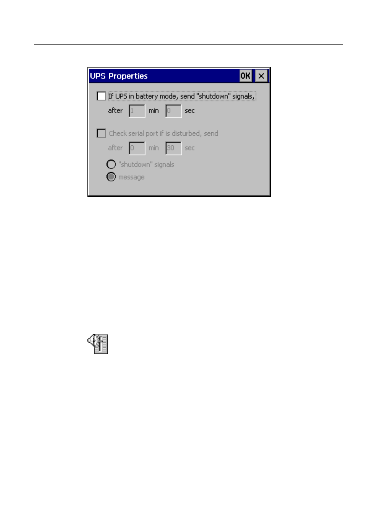
Operating system and configuration
6.2 Windows CE Control Panel
Figure 6-9 "UPS" option
It is possible to define how long the power failure may continue without runtime being
stopped. The driver is suitable for the SITOP DC-UPS Module A.
See also
Open Control Panel (Page 6-2)
Transferring options (Page 7-22)
6.2.12 Volume & Sounds
"Volume & Sounds" option
This is used to change the settings for acoustic signals and operating acknowledgement.
The "Volume & Sounds" option in the "Volume" tab includes the following options:
• acoustic acknowledgement for touch operation
• volume control
The "Sounds" tab is irrelevant for runtime settings.
See also
Open Control Panel (Page 6-2)
TP 270, OP 270, MP 270B (WinCC flexible)
Operating Instructions, Edition 03/2004, 6AV6691-1DD01-0AB0
6-17
Page 88

Operating system and configuration
6.3 Network operation
6.3 Network operation
6.3.1 Basic principles
Purpose
The HMI devices can be connected to an Ethernet network. The MP 270B is equipped with
an on-board Ethernet interface. In the case of TP 270 or OP 270, an NE2000-compatible PC
card is required.
The network function can be used for the following:
• Logging data via the network
• Printing via a network printer
• Storing recipe data records in the network
• Exporting recipe data records from a network
• Importing recipe data records to a network
Requirements
• Transferring projects
• Backing up data
Notice
The HMI device can only be implemented in TCP/IP networks.
The HMI device only has client functionality in the PC network. This means that users
can access files of a subscriber with TCP/IP server functionality from the HMI device via
the network. However, it is not possible to access files on the HMI device via the network
from a PC.
Note
Information on communication using SIMATIC S7 via Ethernet is provided in the "WinCC
flexible Communication" user manual.
Within a TCP/IP network, computers are addressed by means of network names. These
network names are translated from a DNS or WINS server to TCP/IP addresses. Direct
addressing via TCP/IP addresses is not currently supported by the operating system.
Therefore, to ensure the functionality of the HMI device in a TCP/IP network, it is useful to
employ a DNS or WINS server. Appropriate servers are available in common TCP/IP
networks. Please contact your network administrator.
TP 270, OP 270, MP 270B (WinCC flexible)
6-18 Operating Instructions, Edition 03/2004, 6AV6691-1DD01-0AB0
Page 89

Operating system and configuration
6.3 Network operation
Printing via a network printer
The HMI device's operating system does not support the direct alarm logging via a network
printer. All other printer functions such as hardcopy or shift log, are possible via the network
without restriction.
6.3.2 Configuring the HMI device for network operation
Overview
The HMI device must be appropriately configured before setting into network operation. The
configuration is basically divided into the following steps:
• Set computer name of the HMI device
• Configure the network address.
• Set login information
• Save settings
Preparations
Procedure
Before beginning the configuration, request the specific network parameters from the
network administrator. The following information is of particular interest:
• Does the network use DHCP for dynamic assignment of network addresses? If not, get a
new TCP/IP network address for the HMI device.
• What is the TCP/IP address of the default gateway?
• What are the DNS addresses of the name server?
(If DNS is used in the network)
• Which WINS addresses has the name server?
(If WINS is used in the network)
The following instructions describe how to define the general settings. Additional steps or
procedures may be necessary depending on the network infrastructure.
1. Open the Control Panel.
2. Set computer name of the HMI device.
In order to identify the HMI device within the network, it must be assigned a unique name
(device name) within the network using the Control Panel option "Communication"
.
Apply the settings and close the dialog by pressing <ENTER>.
TP 270, OP 270, MP 270B (WinCC flexible)
Operating Instructions, Edition 03/2004, 6AV6691-1DD01-0AB0
6-19
Page 90

Operating system and configuration
6.3 Network operation
3. Configure the network address.
– Use the "Network"
– Select an appropriate network driver in the "Adapters" tab.
Select "Onboard LAN" for HMI devices with an integrated Ethernet card. Select
NE2000-compatible driver for other network cards.
– Press the "Properties" button in order to configure the network characteristics of the
network card used.
Complete the dialog according to the network driver selected.
– If your network uses DHCP, skip this step.
Select the "IP Address" tab then the "Specify an IP Address" option.
Enter the TCP/IP address of the HMI devices (e.g. 233.239.2.100), subnet mask (e.g.
255.255.255.0) and default gateway (e.g. 223.239.2.200).
– Enter the name server address of the network in the "Name Servers" tab.
Close the dialog with <ENTER> or press "OK" to apply the settings.
4. Set login information.
In order to correctly log on to the network, enter your user permissions in the
"Identification" tab. Enter the user name valid for the network or the network server and
the associated password (max. 8 characters).
If the network administrates users via domain controllers, enter the relevant domain
controller name.
Close the dialog with <ENTER> or press "OK" to apply the settings.
option to open the network configuration.
See also
5. Save the settings.
– Switch off the HMI device.
– Before switching the HMI device on, insert the network cable in the corresponding
interface so that a unique IP address can be assigned during the start-up phase.
– Switch the HMI device on again.
Open Control Panel (Page 6-2)
TP 270, OP 270, MP 270B (WinCC flexible)
6-20 Operating Instructions, Edition 03/2004, 6AV6691-1DD01-0AB0
Page 91

Operating system and configuration
6.3 Network operation
6.3.3 Test network
Procedure
When the HMI device has been configured for network operation, connect the network
server via Windows Explorer to test the network. Proceed as follows:
1. Start Windows Explorer via the Windows CE Start menu.
– Keyboard unit:
CTRL
The Windows CE Start menu can be opened by pressing the key combination
ESC
.
– Touch panel unit:
+
Result
– The Windows CE Start menu can be opened by pressing the
button twice
(locking key) on the alphanumeric screen keyboard.
Select the "Windows Explorer" application from the "Programs" program group.
2. Use the "Address" input field to enter the UNC name of the folder or drive provided on the
server.
Example:
The server is called: mrnbg2
The name provided is: data
The resulting UNC name is: \\mrnbg2\data
Note
The use of TCP/IP addresses to address PCs is not supported by the operating system.
For example, the use of the UNC names "\\130.170.10.45\data" is not permitted.
3. After entering the UNC name, press the <ENTER> key.
When all the network settings are correct, Windows Explorer displays the files located under
the directory provided on the TCP/IP server.
Note
In addition, the network program "ipconfig" is available in the operating system.
See also
Configuring the HMI device for network operation (Page 6-19)
TP 270, OP 270, MP 270B (WinCC flexible)
Operating Instructions, Edition 03/2004, 6AV6691-1DD01-0AB0
6-21
Page 92

Operating system and configuration
6.3 Network operation
6.3.4 Configuring network access
Requirements
The network is set up on the HMI device.
Procedure
In order to use the network functions in the WinCC flexible configuration software, specify
the relevant UNC assigned names at those points where paths have been entered for files or
directories.
Example 1: Logs
If you want to perform logging on the server in the example above, replace the predefined
archive memory location "\Storage Card\Logs" with the UNC assigned name for the server,
e.g. "\\mrnbg2\data\logs".
Example 2: Recipe data records
In order to store recipe data records in the network, replace the predefined path name
"\Flash\Recipes" with the UNC assigned name for the server, i.e. "\\mrnbg2\data\recipes".
The same applies for exporting and importing recipe data records using the functions
"ExportDataRecords" and "ImportDataRecords". In this case, replace the parameter "File
name" with the UNC assigned name for the server.
See also
Configuring the HMI device for network operation (Page 6-19)
Test network (Page 6-21)
TP 270, OP 270, MP 270B (WinCC flexible)
6-22 Operating Instructions, Edition 03/2004, 6AV6691-1DD01-0AB0
Page 93

Prepare and backup project
7.1 Transfer project to the HMI device
7.1.1 Commissioning for the first time
Introduction
There is no configuration on the HMI device when commissioning for the first time. In order
to transfer the necessary project data and the runtime software from the configuration
computer to the HMI device, proceed as follows, observing the sequence.
Notice
When starting the first time, observe the safety information on reverse poling.
Caution
7
Always terminate the runtime software before switching off the voltage supply in order to
prevent loss of data.
Press the operating element linked to the "StopRuntime" system function in the project to
stop runtime. Wait until the HMI device displays the loader and then switch off the power
supply.
Note
During the commissioning phase, it is possible to connect an external USB keyboard or
mouse via the USB interface.
TP 270, OP 270, MP 270B (WinCC flexible)
Operating Instructions, Edition 03/2004, 6AV6691-1DD01-0AB0
7-1
Page 94

Prepare and backup project
7.1 Transfer project to the HMI device
Procedure
1. Connect the HMI device to the configuration computer using a suitable standard cable.
Use one of the following interfaces depending on the type of transfer:
– IF2 (serial)
– IF1B (MPI/PROFIBUS DP)
– USB
– Ethernet
Transfer via modem is also possible.
Default setting: Serial connection
2. Switch on the power supply to the HMI device.
When starting the HMI device, the system automatically switches from the loader to the
Transfer menu.
3. Press the "Cancel" button to switch to the loader.
4. Press the "Control Panel" button to switch to the Windows CE Control Panel.
5. Adapt the interface setting (serial, MPI, USB or Ethernet) in the transfer settings.
Default setting: Serial connection
Result
Set date/time
6. Close the Control Panel and switch to the transfer mode.
7. Start transfer of the project on the configuration computer. Please refer to the "WinCC
flexible" user manual for more information on the necessary settings on the configuration
computer.
The configuration computer checks the connection to the HMI device. If the connection is not
available or defective, the configuration computer issues the corresponding error message.
If transfer from the configuration computer is terminated as a result of a compatibility conflict,
the HMI device's operating system must be updated.
If the connection is correct, the new configuration is transferred to the HMI device. Following
successful transfer, the project is started and the start screen of the transferred project
appears.
The date and time must be updated in the following cases:
• Initial startup
• If the HMI device is disconnected from the power supply for an extended period without a
backup battery
See also
Update operating system (Page 7-18)
HMI device loader (Page 6-1)
TP 270, OP 270, MP 270B (WinCC flexible)
7-2 Operating Instructions, Edition 03/2004, 6AV6691-1DD01-0AB0
Page 95

Prepare and backup project
7.2 Transfer
7.1.2 Recommissioning
Purpose
When recommissioning, the existing configuration on the HMI device is replaced by another.
For this to occur, a new project must be transferred from the configuration computer to the
HMI device.
Instructions for transferring a project from the configuration computer to the HMI device can
be found in the "Transfer" section.
The following options are available for switching the HMI device to transfer mode:
• Start transfer mode manually during the HMI device startup phase.
• When the HMI device is in normal operation, start a manual transfer by pressing the
corresponding operating element in the project.
• Start transfer mode manually with the HMI device in normal operation
7.2 Transfer
7.2.1 Start transfer manually
Procedure
1. Connect the HMI device to the configuration computer using a suitable standard cable.
Use one of the following interfaces depending on the type of transfer:
– IF2 (serial)
– IF1B (MPI/PROFIBUS DP)
– USB
– Ethernet
Transfer via modem is also possible.
2. Switch on the power supply to the HMI device.
3. Adapt the interface setting (serial, MPI, USB or Ethernet) in the transfer settings.
4. Close the Control Panel and switch to the transfer mode.
5. Start project transfer on the configuration computer.
TP 270, OP 270, MP 270B (WinCC flexible)
Operating Instructions, Edition 03/2004, 6AV6691-1DD01-0AB0
7-3
Page 96

Prepare and backup project
7.2 Transfer
Result
The configuration computer checks the connection to the HMI device. If the connection is not
available or defective, the configuration computer issues the corresponding error message.
If downloading from the configuration computer is terminated as a result of a compatibility
conflict, the HMI device's operating system must be updated.
If the connection is correct, the new project is transferred to the HMI device. Following
successful transfer, the project is started and the start screen of the transferred project
appears.
7.2.2 Start transfer automatically
Overview
The HMI device can automatically switch to transfer mode during runtime when a transfer is
started on the connected configuration computer. Transfer is completed without intervention
on the HMI device. Therefore, this option is particularly recommended for the test phase of a
new project.
To switch to transfer mode from normal operation, open the "Transfer Settings" window on
the HMI device and activate the required connection and the corresponding "Remote
Control" function.
Notice
When the "Remote Control" option is active, runtime automatically shuts down and switches
to transfer mode. Shutdown is not possible when dialogs are open or a transfer has been
started on the HMI device.
Close the dialog or cancel the transfer process on the configuration computer.
Following the start-up phase, disable the automatic transfer option. This will prevent
inadvertently switching the HMI device to transfer mode, stopping runtime. To do this,
deactivate the "Remote Control" options in the Transfer Settings defined for the HMI device.
TP 270, OP 270, MP 270B (WinCC flexible)
7-4 Operating Instructions, Edition 03/2004, 6AV6691-1DD01-0AB0
Page 97

Prepare and backup project
7.2 Transfer
7.2.3 Transfer mode options
Transfer mode options
The following options can be set for transfer mode:
• The HMI device can be switched to transfer mode automatically when in normal operation
as soon as a transfer is started on the connected configuration computer.
• Select a specific connection type so that transfer can only occur either via a serial
connection, MPI/PROFIBUS-DP, USB or Ethernet connection.
Note
Do not make any other changes when runtime is running or when the HMI device is in
transfer mode.
Setting the communication channel
The "Channel" tab in the Transfer Settings menu can be used to activate the required
communication channel and the "Remote Control" checkbox. In addition to the serial
communication channel, a second channel can also be selected to transfer data from the
configuration computer to the HMI device.
Figure 7-1 "Transfer Settings" dialog, "Channel" tab
Press the "Advanced" button to define the following settings:
• For transfer MPI or PROFIBUS-DP, define the "Address" bus parameter and
"Transmission Rate" and "Highest Station" network parameters.
• Define the driver for transfer via Ethernet.
TP 270, OP 270, MP 270B (WinCC flexible)
Operating Instructions, Edition 03/2004, 6AV6691-1DD01-0AB0
7-5
Page 98

Prepare and backup project
7.2 Transfer
Warning
When the "Remote Control" checkbox is active, ensure that the HMI device is not
inadvertently switched to transfer mode from the configuration computer.
In the case of PROFIBUS DP, changes may only be made here for commissioning
purposes.
Following each modification of the PROFIBUS DP settings, the HMI devices only set one
corresponding standard bus parameter set. In unfavorable conditions, this can lead to
faults on the PROFIBUS.
In order to calculate the bus parameters exactly, the entire bus topology must be known.
Correct definition of the bus parameters for runtime is automatically ensured by the
integrated operation of WinCC flexible in SIMATIC STEP 7.
Notice
If a serial printer is connected to the HMI device, deactivate it by selecting "Remote
Control" checkbox for the serial communication channel. Otherwise, printing is not
possible.
When a configuration is transferred from the configuration computer to the HMI device,
enable a communication channel using the "Enable Channel" option.
If an interface is occupied by other programs, transfer cannot take place via that
interface.
Note
The bus parameters for the MPI transfer, e.g. MPI address, baud rate, etc., are read from
the project currently loaded on the HMI device.
The settings for MPI transfer can be modified. To do this, stop the runtime, modify the
settings and switch to transfer mode. When runtime is subsequently started, the bus
parameters are overwritten by values from the project.
TP 270, OP 270, MP 270B (WinCC flexible)
7-6 Operating Instructions, Edition 03/2004, 6AV6691-1DD01-0AB0
Page 99

Prepare and backup project
7.2 Transfer
Transfer mode directories
The "Directories" tab can be used to specify the following paths (refer to figure below).
Project File
Project backup
Figure 7-2 "Transfer Settings" dialog, "Directories" tab
The predefined storage location for the project file can be changed here. The internal Flash
memory or external Flash cards can be set. During the next transfer process, the project is
stored in the storage location specified.
The predefined storage location for your project source file can be changed here. This file
can be used for restoring (uploading) the configuration. External Flash cards or network
connections can be set.
TP 270, OP 270, MP 270B (WinCC flexible)
Operating Instructions, Edition 03/2004, 6AV6691-1DD01-0AB0
7-7
Page 100

Prepare and backup project
7.2 Transfer
Autostart application
• Path
The memory location for runtime is defined here. This is the application where the project
runs under Windows CE.
• Wait
It is possible to define the number of seconds the loader should remain on screen before
the runtime is started (1 s, 3 s, 5 s, 10 s or constantly). If no runtime software is available,
the device automatically switches to transfer mode.
Notice
With the exception of the "Wait" field, do not change default settings in the fields when
working with WinCC flexible. Otherwise, the HMI device can no longer start the project.
Press the "OK" button or <ENTER> key to confirm the settings currently defined for the
transfer options. Ensure that no buttons have been selected. The dialog is closed and the
Windows CE Control Panel is displayed.
Press the close symbol or <ESC> key to close the dialog and open the Windows CE Control
Panel. Any modifications made to the settings are rejected.
Note
If the HMI device is in transfer mode while changes are made to the transfer settings, the
settings only take effect after the transfer function is restarted. This can occur when the
Control Panel is selected via the Windows Start menu in order to modify the transfer
properties.
7.2.4 Test project
Introduction
There are three ways to test a new project:
• Test the project on the configuration computer
• Test project offline
• Test project online
Test the project first on the configuration computer using the simulator. Then, always test the
project online.
The material supplied with WinCC flexible contains a simulation program which can be used
to test the project on the configuration computer without the necessity of connecting a PLC
or HMI device. Detailed information on this is available in the "WinCC flexible" user manual
and in the WinCC flexible online help.
TP 270, OP 270, MP 270B (WinCC flexible)
7-8 Operating Instructions, Edition 03/2004, 6AV6691-1DD01-0AB0
 Loading...