

Siemens SIMATIC NET TeleControl SINAUT ST7 System Manual
___________________
___________________
___________________
___________________
___________________
___________________
___________________
___________________
SIMATIC NET
Industrial Remote Communication TeleControl
SINAUT ST7 station control system
System Manual
Volume 1: System and Hardware
09/2016
C79000
Preface
Properties of the SINAUT
components
1
Network structures and
topologies
2
Installation guide
3
Installing and putting a TIM
into operation
4
Installation and
commissioning of the
modems and routers
5
Technical specifications
6
Certifications and approvals
7
References
A
-G8976-C178-10
Siemens AG
Division Process Industries and Drives
Postfach 48 48
90026 NÜRNBERG
GERMANY
C79000-G8976-C178-10
Ⓟ
Copyright © Siemens AG 2009 - 2016.
All rights reserved
Legal information
Warning notice system
DANGER
indicates that death or severe personal injury will result if proper precautions are not taken.
WARNING
indicates that death or severe personal injury may result if proper precautions are not taken.
CAUTION
indicates that minor personal injury can result if proper precautions are not taken.
NOTICE
indicates that property damage can result if proper precautions are not taken.
Qualified Personnel
personnel qualified
Proper use of Siemens products
WARNING
Siemens products may only be used for the applications described in the catalog and in the relevant technical
re required to ensure that the products operate safely and without any problems. The permissible
ambient conditions must be complied with. The information in the relevant documentation must be observed.
Trademarks
Disclaimer of Liability
This manual contains notices you have to observe in order to ensure your personal safety, as well as to prevent
damage to property. The notices referring to your personal safety are highlighted in the manual by a safety alert
symbol, notices referring only to property damage have no safety alert symbol. These notices shown below are
graded according to the degree of danger.
If more than one degree of danger is present, the warning notice representing the highest degree of danger will
be used. A notice warning of injury to persons with a safety alert symbol may also include a warning relating to
property damage.
The product/system described in this documentation may be operated only by
task in accordance with the relevant documentation, in particular its warning notices and safety instructions.
Qualified personnel are those who, based on their training and experience, are capable of identifying risks and
avoiding potential hazards when working with these products/systems.
Note the following:
documentation. If products and components from other manufacturers are used, these must be recommended
or approved by Siemens. Proper transport, storage, installation, assembly, commissioning, operation and
maintenance a
All names identified by ® are registered trademarks of Siemens AG. The remaining trademarks in this publication
may be trademarks whose use by third parties for their own purposes could violate the rights of the owner.
We have reviewed the contents of this publication to ensure consistency with the hardware and software
described. Since variance cannot be precluded entirely, we cannot guarantee full consistency. However, the
information in this publication is reviewed regularly and any necessary corrections are included in subsequent
editions.
for the specific
10/2016 Subject to change

Preface
Note
Discontinuation of modules
As of 01.10.2016 the following products have the status "discontinued":
•
•
•
•
•
If there are successors to the discontinued devices, you will find these in the notifications
listed above on the Internet.
What's new in SINAUT ST7?
Engineering software
Modem MD2
Modem MD3
LTOP1 / LTOP2
Accessories:
Overvoltage protection module as replacement part for LTOP1 and LTOP2, DIN rail
adapter, various plug-in cables
Observe the product notifications on the Internet:
Link: (https://support.industry.siemens.com/cs/ww/en/ps/15915/pm)
EGPRS router MD741-1
Observe the following product notification:
Link: (https://support.industry.siemens.com/cs/ww/en/view/62607452)
SINAUT ST7 provides the following new functions:
●
New version of the SINAUT ST7 configuration and diagnostics software V5.5 SP2
After release of the version V5.4 of the engineering software small functional
improvements were made. In addition to this, the following functions are new:
– Configuration of a proxy TIM 3V-IE Advanced as substitute for a CP 1243-8 IRC
The 1243-8 IRC can be configured in STEP 7 Basic as of version V13.0 SP1.
You will find the description in Volume 2 in section 3.2, PROXY CP1243-8 IRC.
– Improvement of the selective connection configuration by selecting individual
subscribers
– Passing of the key exchange interval to the MODEM MD720 when using the MSC
protocol
– Errors corrected in the time-of-day synchronization of a TIM by the CPU
You will find the description in Volume 2 in section 3.5, Synchronization of an Ethernet
TIM by the CPU.
SINAUT ST7 station control system
System Manual, 09/2016, C79000-G8976-C178-10
3

Preface
Block library TD7onCPU
TIM firmware
Replaced documentation
Purpose of the manual
Volume 1: System & Hardware
Volume 2: Software
To upgrade to this version, a full version of the SINAUT engineering software V5.0 must
be installed.
The engineering software V5.5 SP2 can be used with STEP 7 as of version V5.4 SP4.
To use the engineering software, a Windows operating system is required that is
compatible with the installed STEP 7 version.
You will find details on the ordering data and operating systems of the engineering
software in volume 2 of the system manual in the section SINAUT ST7 software: Ordering
data and compatible operating systems.
●
New version of the block library TD7onCPU V2.2 SP4 + Hotfix 1
– New block "FC-PathStatus" to display the main and substitute path to the remote
communications partner.
The block can be used as of version V5.5 SP1 of the engineering software and as of
TIM firmware V2.5.4.
– The block library can now be used both in a standalone TIM in an S7-400 and an S7-
400H also with only one single CPU (single mode).
●
The new functions of the SINAUT engineering software named above are supported by
firmware version V2.5.4 for the following TIM modules:
TIM 3V-IE, TIM 3V-IE Advanced, TIM 4R-IE
This manual replaces the manual release 08/2011 (C79000-G89xx-C222-07).
For older releases of the manual, see below, section Version history (Page 7).
The SINAUT ST7 system manual is split into two complementary volumes.
●
This documentation will support you on your way to successful application of SINAUT
ST7. This introduces you to the topic in clear and straightforward steps and provides you
with an overview of the hardware components of the SINAUT ST7 station control system.
You will be supported during the planning of network structures and topologies and will
see how to install and commission SINAUT components based on the installation
guidelines.
●
This documentation provides you with an overview of the software components of the
SINAUT ST7 station control system. You will see how individual components are
configured. Diagnostics and service options are also explained.
SINAUT ST7 station control system
4 System Manual, 09/2016, C79000-G8976-C178-10

Preface
Note
Documentation for the SINAUT ST1 system and older modules
This release of the
on the SINAUT
•
•
If
this manual. You will find release 05/2007 on the Internet pages of Siemens Industry Online
Support at the following address:
Link: (
The documents have the following IDs.
•
•
Validity of this manual
Further information on the Internet
Security information
manual "SINAUT ST7" (volume 1 + 2) no longer has detailed information
ST1 system and the following older modules:
All previous TIM 3 modules: TIM 3V, TIM 32, TIM 33, TIM 34
TIM 4V, TIM 4VD, TIM 42, TIM 42D, TIM 43, TIM 43D, TIM 44, TIM 44D
you require information on these modules or on SINAUT ST1, refer to release 05/2007 of
https://support.industry.siemens.com/cs/ww/en/ps/15931/man)
Volume 1: 24621696
Volume 2: 24619519
This manual applies to the following ST7 modules and software versions:
● TIM 3V-IE, TIM 3V-IE Advanced, TIM 4R-IE, TIM 4R / 4RD
● SINAUT ST7 configuration and diagnostics software for the PG V5.4
● SINAUT TD7 library for the CPU V2.2 SP2
● SINAUT TIM firmware V4.4.0 for the TIM 4
● SINAUT TIM firmware V2.5 for the TIM 3V-IE variants
● SINAUT TIM firmware V2.5 for the TIM 4R-IE
You will find further information on the TeleControl ST7 products on the Internet at the
following address:
Link: (https://support.industry.siemens.com/cs/ww/en/ps/15931/man)
There select the required information under "Entry type" (for example "Updates", "Manuals",
"FAQs" etc.).
Siemens provides products and solutions with industrial security functions that support the
secure operation of plants, systems, machines and networks.
In order to protect plants, systems, machines and networks against cyber threats, it is
necessary to implement – and continuously maintain – a holistic, state-of-the-art industrial
security concept. Siemens’ products and solutions only form one element of such a concept.
SINAUT ST7 station control system
System Manual, 09/2016, C79000-G8976-C178-10
5

Preface
License conditions
Note
Open source software
Read the license conditions for open source software carefully before using the product.
SIMATIC NET glossary
Training, Service & Support
Customer is responsible to prevent unauthorized access to its plants, systems, machines
and networks. Systems, machines and components should only be connected to the
enterprise network or the internet if and to the extent necessary and with appropriate security
measures (e.g. use of firewalls and network segmentation) in place.
Additionally, Siemens’ guidance on appropriate security measures should be taken into
account. For more information about industrial security, please visit
Link: (http://www.siemens.com/industrialsecurity)
Siemens’ products and solutions undergo continuous development to make them more
secure. Siemens strongly recommends to apply product updates as soon as available and to
always use the latest product versions. Use of product versions that are no longer supported,
and failure to apply latest updates may increase customer’s exposure to cyber threats.
To stay informed about product updates, subscribe to the Siemens Industrial Security RSS
Feed under
Link: (http://www.siemens.com/industrialsecurity).
You will find license conditions in the following documents on the supplied data medium:
● OSS_TIM-ST7_86.pdf
● OSS_SINAUT-ES_86.pdf
Explanations of many of the specialist terms used in this documentation can be found in the
SIMATIC NET glossary.
You will find the SIMATIC NET glossary here:
● SIMATIC NET Manual Collection or product DVD
The DVD ships with certain SIMATIC NET products.
● On the Internet under the following address:
Link: (https://support.industry.siemens.com/cs/ww/en/view/50305045)
You will find information on training, service and support in the multilanguage document
"DC_support_99.pdf" on the Internet pages of Siemens Industry Online Support:
Link: (https://support.industry.siemens.com/cs/ww/en/view/38652101)
SINAUT ST7 station control system
6 System Manual, 09/2016, C79000-G8976-C178-10

Preface
Trademarks
Version history
Release 09/2014 of the manual (C79000-G89xx-C222-09)
New functions:
Validity of the manual:
Release 08/2011 of the manual (C79000-G89xx-C222-08)
New functions:
The following and possibly other names not identified by the registered trademark sign ® are
registered trademarks of Siemens AG:
SINAUT, TIM, SCALANCE, MODEM MD720, MD741-1, Modem MD2 / MD3 / MD4, LTOP
The previous versions of the manual described the innovations and versions listed below.
● New version of the SINAUT ST7 configuration and diagnostics software V5.4
– Time-of-day synchronization of the TIM 4R-IE using NTP
You will find the description in Volume 2 in section 3 (Configuration in STEP 7 >
Configuration of TIM modules > "NTP" tab).
– Synchronization of the TIM time of day by the CPU
You will find the description in Volume 2 in the section 3 (Configuration in STEP 7 >
Configuration of the time-of-day synchronization).
– MSCsec protocol: Secure transfer, authentication with key exchange
You will find the description in Volume 2 in section 2 (Configuration - Overview >
GPRS/Internet Communication).
● New firmware version V2.5 for the TIM modules TIM 3V-IE, TIM 3V-IE Advanced,
TIM 4R-IE
The functions named above among the innovations of the configuration software are new.
● TIM 3V-IE, TIM 3V-IE Advanced, TIM 4R-IE, TIM 4R / 4RD
● SINAUT ST7 configuration and diagnostics software for the PG V5.4
● SINAUT TD7 library for the CPU V2.2 SP2
● SINAUT TIM firmware V4.4.0 for the TIM 4
● SINAUT TIM firmware V2.5 for the TIM 3V-IE variants
● SINAUT TIM firmware V2.5 for the TIM 4R-IE
● New version of "SINAUT ST7 configuration and diagnostics software" V5.2
● Version "SINAUT ST7 configuration and diagnostics software" V5.1
● New SINAUT TD7 library V2.2 SP2 for the CPU
SINAUT ST7 station control system
System Manual, 09/2016, C79000-G8976-C178-10
7

Preface
Validity of the manual:
Release 07/2009 of the manual (C79000-G89xx-C222-07)
New functions:
Validity of the manual:
Release 05/2007 of the manual (C79000-G89xx-C222-06)
New functions:
● SINAUT ST7 configuration and diagnostics software for the PG V5.2
● SINAUT TD7 library for the CPU V2.2 SP2
● SINAUT TIM firmware V4.4.0 for the TIM 4
● SINAUT TIM firmware V2.3 for the TIM 3V-IE variants
● SINAUT TIM firmware V2.3 for the TIM 4R-IE
● New version "SINAUT ST7 configuration software for the PG/PC" V5.0
– The Ethernet TIMs can be configured for communication via the MSC protocol. This
allows the use of the GPRS/GSM modem SINAUT MD720-3 even in SINAUT in
Internet/GPRS networks. An encrypted connection can be established from an
Ethernet TIM to the Internet via a DSL modem.
– The time slot method can now also be configured with the "SINAUT ST7 configuration
software for the PG/PC" as of V5.0 for a master TIM without DCF7 receiver, if a
TIM 4R-IE with an Ethernet connection to an ST7cc/ST7sc PC is used as the master
TIM.
The configuration software Version V5.0 can be used with STEP 7 as of Version V5.4
Service Pack 4.
The configuration software version V5.0 is supported by the following operating systems:
– Windows XP Professional SP2
– Windows Server 2003 SP2
– Windows Vista 32 Bit Ultimate and Business (with or without SP1)
● New firmware version V2.0 for all Ethernet TIM modules
The new firmware supports the MSC protocol.
● SINAUT ST7 configuration software for the PG/PC V5.0
● SINAUT TD7 library for the CPU V2.2
● SINAUT TIM firmware V4.3.9 for the TIM 4
● SINAUT TIM firmware V2.0 for the TIM 3V-IE variants
● SINAUT TIM firmware V2.0 for the TIM 4R-IE
● New product "TIM 4R-IE" for connecting SINAUT via WAN and Ethernet
● New product version "SINAUT ST7 configuration software for the PG/PC" V4.1
SINAUT ST7 station control system
8 System Manual, 09/2016, C79000-G8976-C178-10

Preface
Validity of the manual:
Release 10/2006 of the manual (C79000-G89xx-C222-05)
New functions:
Validity of the manual:
● SINAUT ST7 configuration software for the PG/PC V4.1
● SINAUT TD7 library for the CPU V2.2
● SINAUT TIM firmware V4.3.7 for the TIM 3 / TIM 4
● SINAUT TIM firmware V1.2 for the TIM 3V-IE variants
● SINAUT TIM firmware V1.0 for the TIM 4R-IE
● New product versions
– SINAUT ST7 configuration software for the PG/PC V4.0
– SINAUT TD7 library for the CPU V2.2 with new blocks for communication via P-bus
● New hardware for GSM and GPRS
– GPRS modem MD740-1 for secure packet-oriented communication via GSM mobile
wireless (GPRS)
– GSM modem MD720-3 as replacement for the discontinued GSM modem MC45 for
establishing dial-up connections via the GSM mobile wireless network; possible as of
firmware V1.7.3 of the MD720-3
● SINAUT ST7 configuration software for the PG/PC V4.0
● SINAUT TD7 library for the CPU V2.2
● SINAUT TIM firmware V4.3.7 for the TIM 3 / TIM 4
● SINAUT TIM firmware V1.2 for the TIM 3V-IE variants
SINAUT ST7 station control system
System Manual, 09/2016, C79000-G8976-C178-10
9

Preface
SINAUT ST7 station control system
10 System Manual, 09/2016, C79000-G8976-C178-10

Table of contents
Preface ................................................................................................................................................... 3
1 Properties of the SINAUT components .................................................................................................. 15
1.1 Area of application .................................................................................................................. 15
1.2 Components in a SINAUT ST7 system .................................................................................. 16
1.3 Properties of the TIM modules ................................................................................................ 17
1.3.1 Overview of All TIM Variants .................................................................................................. 19
1.3.2 TIM 3V-IE / TIM 3V-IE Advanced ........................................................................................... 19
1.3.2.1 The TIM 3V-IE variants ........................................................................................................... 19
1.3.2.2 Front view of the TIM 3V-IE variants with closed front panel ................................................. 22
1.3.2.3 Front view of the TIM 3V-IE variants with front panel removed .............................................. 23
1.3.2.4 LEDs of the TIM 3V-IE variants .............................................................................................. 23
1.3.2.5 Pinout of the ports ................................................................................................................... 25
1.3.2.6 Standard connecting cables for the TIM 3V-IE variants ......................................................... 25
1.3.3 TIM 4R-IE ................................................................................................................................ 29
1.3.3.1 The TIM 4R-IE ........................................................................................................................ 29
1.3.3.2 Design of the TIM 4R-IE ......................................................................................................... 30
1.3.3.3 Front view of the TIM 4R-IE with closed front panel ............................................................... 32
1.3.3.4 Front view of the TIM 4R-IE with removed front panel ........................................................... 33
1.3.3.5 LEDs of the TIM 4R-IE ............................................................................................................ 34
1.3.3.6 Pinout of the ports ................................................................................................................... 35
1.3.3.7 Standard connecting cables for the TIM 4R-IE ....................................................................... 36
1.3.4 TIM 4 / TIM 4RD ..................................................................................................................... 41
1.3.4.1 The TIM 4 variants .................................................................................................................. 41
1.3.4.2 Design of the TIM 4 variants ................................................................................................... 43
1.3.4.3 Front view of the TIM 4 with closed front panels .................................................................... 44
1.3.4.4 Front view of the TIM 4 with removed front panels ................................................................. 45
1.3.4.5 LEDs of the TIM 3 / TIM 4 ....................................................................................................... 46
1.3.4.6 Pinout of the X1 and X2 connectors ....................................................................................... 46
1.3.4.7 Standard connecting cables that can be connected to connector X1 .................................... 48
1.3.4.8 View of the TIM 4 from above ................................................................................................. 52
1.3.4.9 View of the TIM 3 / TIM 4 from below ..................................................................................... 53
1.4 The classic SINAUT ST7 modems ......................................................................................... 55
1.4.1 The modem variants ............................................................................................................... 55
1.4.2 Overview of the modems MD2, MD3, MD4 and accessories ................................................. 56
1.5 Mobile wireless components ................................................................................................... 57
1.5.1 Areas of application ................................................................................................................ 57
1.5.2 Antennas ................................................................................................................................. 58
1.6 Radio clock components
1.6.1 Accessories for DCF77 ........................................................................................................... 59
1.6.2 GPS receiver ........................................................................................................................... 61
1.6.3 Overview of the radio clock components ................................................................................ 63
1.7 LTOP overvoltage protection modules ................................................................................... 64
SINAUT ST7 station control system
System Manual, 09/2016, C79000-G8976-C178-10
......................................................................................................... 59
11

Table of contents
2 Network structures and topologies ........................................................................................................ 75
3 Installation guide ................................................................................................................................... 85
4 Installing and putting a TIM into operation ............................................................................................ 121
5 Installation and commissioning of the modems and routers .................................................................. 141
1.7.1 Variants and overview of the LTOP overvoltage protection modules .................................... 64
1.8 Connecting cables ................................................................................................................. 65
1.8.1 Cable for connecting TIM and modem modules .................................................................... 66
1.8.2 Cables for the WAN connection of the modems .................................................................... 67
1.8.3 TIM 4R / 4RD interface adapter cable ................................................................................... 68
1.9 SINAUT ST7cc, the add-on for WinCC .................................................................................. 68
1.9.1 Area of application ................................................................................................................. 68
1.9.2 The special properties of SINAUT ST7cc .............................................................................. 69
1.10 SINAUT ST7sc SCADA Connect software ............................................................................ 71
1.10.1 The special properties of SINAUT ST7sc .............................................................................. 72
2.1 Overview of the possible network types ................................................................................ 75
2.2 Configurations ........................................................................................................................ 76
2.2.1 Configurations with IP-based WAN........................................................................................ 76
2.2.2 Configurations with classic WAN ........................................................................................... 81
3.1 Installing the TIM 3V-IE variants in an S7-300 ...................................................................... 85
3.2 Installing the TIM 4R-IE in an S7-300 .................................................................................... 94
3.3 Standalone TIM 4R-IE with an S7-400 or PC ...................................................................... 104
3.4 Installation of the TIM 4 as CP in an S7-300 ....................................................................... 108
3.5 Standalone TIM 4 with an S7-400 or PC ............................................................................. 112
4.1 Horizontal and vertical installation ....................................................................................... 121
4.2 Dimensions for installation of the SINAUT ST7 components .............................................. 122
4.3 Options for connecting up and settings for the TIM 4R or TIM 4RD .................................... 122
4.3.1 Possible attachments and settings for the TIM 4R and TIM 4RD ........................................ 123
4.4 Installing a TIM ..................................................................................................................... 126
4.4.1 Important notes on using the device .................................................................................... 126
4.4.2 Introduction .......................................................................................................................... 128
4.4.3 Installing a TIM module as CP ............................................................................................. 128
4.4.4 Installing a TIM 4 / TIM 4R-IE as a standalone device ........................................................ 129
4.4.5 Horizontal and vertical installation ....................................................................................... 130
4.4.6 Connecting the TIM to the power supply ............................................................................. 131
4.5 Configuration ........................................................................................................................ 133
4.6 Startup activities of the TIM module..................................................................................... 133
4.6.1 Startup of the TIM 3V-IE variants......................................................................................... 133
4.6.2 Startup activities of the TIM 4R-IE ....................................................................................... 136
4.6.3 Startup behavior of the TIM 4 .............................................................................................. 138
5.1 Overview .............................................................................................................................. 141
5.2 Important notes on using the device .................................................................................... 141
SINAUT ST7 station control system
12 System Manual, 09/2016, C79000-G8976-C178-10

Table of contents
6 Technical specifications ...................................................................................................................... 235
7 Certifications and approvals ................................................................................................................ 259
5.3 GSM/GPRS modem MD720-3 .............................................................................................. 143
5.3.1 Displays and connectors ....................................................................................................... 144
5.3.2 Connecting the MD720-3 to the TIM and antenna ............................................................... 147
5.3.3 Prerequisites for operation .................................................................................................... 148
5.4 GPRS/GSM router MD741-1 ................................................................................................ 148
5.4.1 Displays and connectors ....................................................................................................... 149
5.4.2 Connecting the MD741-1 to the TIM and antenna ............................................................... 152
5.4.3 Prerequisites for operation .................................................................................................... 152
5.5 MD2 dedicated line modem .................................................................................................. 153
5.5.1 Displays and connectors accessible from the front .............................................................. 154
5.5.2 Configuration switches accessible from above ..................................................................... 160
5.5.3 Connectors and configuration switches accessible from below ........................................... 166
5.5.4 Connecting the MD2 with TIM, LTOP and dedicated line ..................................................... 169
5.6 LTOP line transformer with overvoltage protection .............................................................. 181
5.6.1 Structure ............................................................................................................................... 181
5.6.2 Connecting up the MD2 modem ........................................................................................... 183
5.7 Analog dial-up modem MD3 ................................................................................................. 186
5.7.1 Indicators and connectors accessible from the front ............................................................ 186
5.7.2 Configuration switches accessible from above ..................................................................... 193
5.7.3 Connectors and configuration switches accessible from below ........................................... 203
5.7.4 Connecting the MD3 with a TIM and TAE6 outlet ................................................................ 206
5.7.5 Connecting the MD3 with TIM, LTOP and dedicated line ..................................................... 207
5.7.6 User-configurable profiles ..................................................................................................... 213
5.7.7 LTOP line transformer with overvoltage protection .............................................................. 216
5.8 ISDN dial-up modem MD4 .................................................................................................... 217
5.8.1 Indicators and connectors accessible from the front ............................................................ 218
5.8.2 Configuration switches accessible from above ..................................................................... 223
5.8.3 Connectors and configuration switches accessible from below ........................................... 227
5.8.4 Connecting the MD4 with a TIM and ISDN outlet ................................................................. 229
5.9 Installing and putting a SINAUT MD2, MD3, MD4 modem into operation ............................ 230
5.9.1 Installation ............................................................................................................................. 230
5.9.2 Installation on an S7-300 rail ................................................................................................ 230
5.9.3 Installation on a 35 mm standard rail .................................................................................... 232
5.9.4 Horizontal and vertical installation ........................................................................................ 232
5.9.5 Connecting to the power supply ........................................................................................... 233
6.1 Technical specifications of the TIM 3V-IE variants ............................................................... 235
6.2 Technical specifications of the TIM 4R-IE ............................................................................ 240
6.3 Technical specifications of the TIM 4 variants ...................................................................... 244
6.4 Current consumption and power loss of the SINAUT ST7 components .............................. 246
6.5 Technical specifications of the SINAUT ST7 modems ......................................................... 249
6.6 Technical specifications of the radio clock components ....................................................... 254
6.7 Technical specifications of the LTOP overvoltage protection module .................................. 257
SINAUT ST7 station control system
System Manual, 09/2016, C79000-G8976-C178-10
13

Table of contents
A References .......................................................................................................................................... 271
Glossary .............................................................................................................................................. 275
Index ................................................................................................................................................... 293
7.1 Approvals for the TIM 4R/4RD and the SINAUT modems .................................................. 259
7.2 Additional approvals for SINAUT products for the analog telephone network .................... 262
7.3 Approvals for the TIM 3V-IE variants and the TIM 4R-IE .................................................... 265
SINAUT ST7 station control system
14 System Manual, 09/2016, C79000-G8976-C178-10

1
1.1
Area of application
Process control over WAN and Ethernet
The control center
The SINAUT WAN networks
SINAUT® ST7 is a system based on SIMATIC® S7 for fully automatic monitoring and control
of process stations that exchange data with another and with one or more control centers
over a WAN (wide area network) or Ethernet (TCP/IP).
The following can currently be used as control centers:
● SIMATIC controllers S7-300 or S7-400. This solution is suitable for less complex control
centers, in which only a current image of the process data in the stations is required. By
entering commands, setpoints or parameters, it is possible to intervene in the process
control of the stations.
● SINAUT ST7cc, the PC control center (single or redundant) based on WinCC. This is a
control center system for SINAUT ST7 specially tailored to the event-driven and timestamped data transmission of the SINAUT system.
● SINAUT ST7sc, the link to control centers of other vendors over OPC. Using the "Data
Access Interface", the SINAUT telecontrol technology can also interface with the control
center systems of other vendors. ST7sc has extensive buffer mechanisms that prevent
data loss, for example, if the OPC client fails.
The following WANs can be used for data transmission:
● Dedicated lines (copper or fiber-optic cables)
● Private wireless networks (optionally with time slots)
● Analog telephone network
● Digital ISDN network
● Mobile wireless networks (GSM)
All networks can be combined as necessary. Redundant paths are also possible. Star, bus
(linear) and node structures can be implemented.
SINAUT ST7 station control system
System Manual, 09/2016, C79000-G8976-C178-10
15

Properties of the SINAUT components
SINAUT over Ethernet
Change-driven data transmission
Local data storage
Date and time always precise
SINAUT remote programming
Alerting over SMS
1.2
Components in a SINAUT ST7 system
1.2 Components in a SINAUT ST7 system
SINAUT communication is possible between station and control center and between stations
over Ethernet or IP-based networks. This includes transmission using the GPRS service in
mobile wireless networks (GSM networks). The prerequisite is continually available
connections.
The SINAUT software in the stations allows change-driven process data exchange with the
control center and between the individual CPUs.
One special characteristic of the TIM communications module used in the SINAUT ST7
system is the local storage of data messages (including time stamp) if there is a problem on
the communication link, if a partner fails or to optimize costs on dial-up networks.
The CPUs and even the control center (for example ST7cc) can be supplied throughout the
network with the date and time using a DCF77 radio clock. The systems therefore always
have a precise time of day including standard/daylight-saving time adjustment. Instead of
DCF77, GPS (Global Positioning System) can also be used as the time source.
All the diagnostic and programming functions provided by SIMATIC and SINAUT for station
automation and SINAUT communication can be used beyond the SINAUT networks while
process data transmission is active.
The CPUs can transmit event-driven SMS messages to GSM mobile phones to alert standby
personnel. This is supported by both variants of the TD7 software (TD7onCPU and
TD7onTIM) although the range of functions is slightly different. This is described in detail in
the SINAUT ST7 system manual, volume 2 "Software".
The SINAUT ST7 system is based on the S7-300 and S7 400 SIMATIC systems and on
WinCC. It expands these systems by adding the special SINAUT hardware and software
components listed below.
SINAUT ST7 station control system
16 System Manual, 09/2016, C79000-G8976-C178-10

Properties of the SINAUT components
Hardware components
Software components
1.3
Properties of the TIM modules
1.3 Properties of the TIM modules
The range of hardware components includes:
● TIM communications modules
● MD modem modules
Classic modems for dedicated line, analog and ISDN dial-up networks
● Mobile wireless components
e.g. GSM modem MD720, 2.5G router SCALANCE M874
● LTOP overvoltage protection modules
● Radio clock components
● Connecting cables
The range of software components includes:
● Standard software for SINAUT ST7 consisting of the individual packages
– SINAUT TD7 library (TD7onCPU). This contains blocks for the S7-CPU.
– SINAUT TD7 library (TD7onTIM). Blocks on the TIM (no memory required on the
CPU)
– SINAUT ST7 configuration and diagnostic software for the programming device
● SINAUT ST7cc, the expansion package for WinCC consisting of
– ST 7 Server, the interface between ST7 and WinCC
– ST7cc Config, the configuration tool for ST7cc
● SINAUT ST7sc, the SCADA Connect software, consisting of
– OPC server, the interface between ST7 and an OPC client
– ST7sc Config, the configuration tool for ST7sc
The standard software for SINAUT ST7 is described in detail in Volume 2 of this system
manual. You will find the required version of the configuration and diagnostics software in
Preface (Page 3).
The SINAUT ST7cc and SINAUT ST7sc software packages are described in separate
manuals, see /4/ (Page 272) and /5/ (Page 272).
The central component of the SINAUT hardware is the TIM communications module
(Telecontrol Interface Module). This handles the data traffic for the S7-CPU or for the control
center PC with the aid of the SINAUT ST7 protocol via the relevant SINAUT network.
The TIM is housed in an S7-300 enclosure and is available in three basic versions:
SINAUT ST7 station control system
System Manual, 09/2016, C79000-G8976-C178-10
17

Properties of the SINAUT components
TIM 3V-IE / TIM 3V-IE Advanced
Note
Low cycle monitoring time of the CPU
If the cycle monitoring time of the CPU is set to very low values, for example 1 ms, this can
lead to malfunctions on the TIM
the CPU or use a TIM
TIM 4R-IE
TIM 4
1.3 Properties of the TIM modules
The TIM 3V-IE is a SINAUT communications module for the SIMATIC S7-300. It has an RS232 interface to which a suitable modem can be connected. It also has an RJ-45 interface
that allows SINAUT communication over IP-based networks (LAN or WAN).
The TIM 3V-IE is available in a standard and advanced version:
● TIM 3V-IE
With the TIM 3V-IE either the Ethernet interface or the RS-232 interface can be used for
the SINAUT communication.
● TIM 3V-IE Advanced
With the TIM 3V-IE Advanced, the two interfaces can be used at the same time for
SINAUT communication. The two transmission paths can be completely independent of
each other or form a redundant transmission path.
3V-xxx. In this case, increase the cycle monitoring time of
4R-xxx.
The TIM 4R-IE is suitable for installation in a SIMATIC S7-300 as a communications module
and can also be connected over Ethernet to one or more SIMATIC S7-400s and to ST7cc or
ST7sc PC control centers as a standalone device.
It has two combined RS-232/RS-485 interfaces to which a classic WAN (dedicated line or
dial-up network) can be connected via a suitable modem. It also has two RJ-45 interfaces
that allow SINAUT communication over Ethernet-based networks (LAN or WAN).
All four interfaces can be used at the same time for SINAUT communication. The four
transmission paths can all be different and operated independently. The two pairs of
interfaces can also form a redundant transmission path.
The TIM 4 is suitable for installation in the SIMATIC S7-300 as a communications module
and can also be connected via their MPI ports to one or more SIMATIC S7-300/-400s and to
ST7cc or ST7sc PC control centers as a standalone device.
It has two WAN connectors in the form of RS-232/RS-485 ports to which a suitable external
modem can be connected.
The two WANs that can be connected to a TIM 4 may be of the same type or different, for
example dedicated line plus telephone network. The two transmission paths can be either
completely independent of each other or form a redundant transmission path.
The TIM 4RD is equipped with a DCF77 radio clock receiver.
SINAUT ST7 station control system
18 System Manual, 09/2016, C79000-G8976-C178-10

Properties of the SINAUT components
1.3.1
Overview of All TIM Variants
Can be used in conjunction with
MPI
port
Ethernet port
RS-232/
RS-485 for
external
modem
Integrated
modem
DCF77 radio
clock2)
Order no.
S7-300
S7-400
3BA00
Advanced
3CA00
4AA90
4AD90
4BA00
1.3.2
TIM 3V-IE / TIM 3V-IE Advanced
1.3.2.1
The TIM 3V-IE variants
1.3 Properties of the TIM modules
All TIMs are supplied with a bus module connector allowing the TIM to be installed in an
S7-300 as a CP. The adapter cable for the second RS-232/RS-485 port ships with the
TIM 4R variant. The DCF77 adapter cable ships with the TIM 4RD with DCF77 radio clock
receiver.
The following table provides an overview of all TIM variants and their order numbers.
Table 1- 1 Overview of All TIM Variants
TIM 3V-IE • no no 1 1 (RS-232) no no 6NH7 800-
TIM 3V-IE
TIM 4R3) • • • no 2 no no 6NH7 800-
TIM 4RD 3) • • • no 2 no • 6NH7 800-
TIM 4R-IE • • no 2 2 no no 6NH7 800-
• • 1) no 1 1 (RS-232) no no 6NH7 800-
1) The TIM can be connected either via the MPI interface of its S7-300-CPU or via its own Ethernet interface to an S7-400 or to the ST7cc or
ST7sc PC.
2) Including DCF77 adapter cable 6NH7700-0AD15
3) Including adapter cable 6NH7700-0AS05 for the second serial RS-232/RS-485 port
The TIM 3V-IE is available in standard and advanced versions. The two communications
processors share the following properties:
● TIM without integrated modem, single width
● For installation as a communications processor (CP) in an S7-300
SINAUT ST7 station control system
System Manual, 09/2016, C79000-G8976-C178-10
● With a TIM 3V-IE, an S7-300 CPU or a C7 control system can then handle SINAUT
communication:
– Via a classic SINAUT WAN network with SINAUT partners
– Over an IP-based network (WAN or LAN) with SINAUT ST7 subscribers
19
Properties of the SINAUT components
TIM 3V-IE
TIM 3V-IE Advanced
redundant transmission path
Data memory
16,000 data messages
32,000 data messages
TIMs in the rack
S7-300 CPU
1.3 Properties of the TIM modules
● It has two interfaces:
– RS-232 interface for connection of required WAN transmission equipment (classic
SINAUT WAN)
To allow use of GPRS, the switchable serial interface of a station TIM 3V-IE can be
connected to a GSM network via the GSM modem MD720-3. This requires the MSC
protocol to be enabled in the STEP 7 > Properties dialog of the TIM > Interfaces tab.
The WAN interface then behaves like an Ethernet interface.
– RJ-45 interface for attachment to Ethernet
One of the two interfaces can be connected.
● The SINAUT TD7 software is integrated on the TIM (TD7onTIM)
● Modules can be replaced without the need for a programming device
The following properties are different on the TIMs:
SINAUT communication over RS-232 or RJ-45 RS-232
Use as
Number of S7 connections 8 20
Can be combined with other
Communication over MPI of the
• Station • Station
• Nodes
• Master station
no yes
no yes
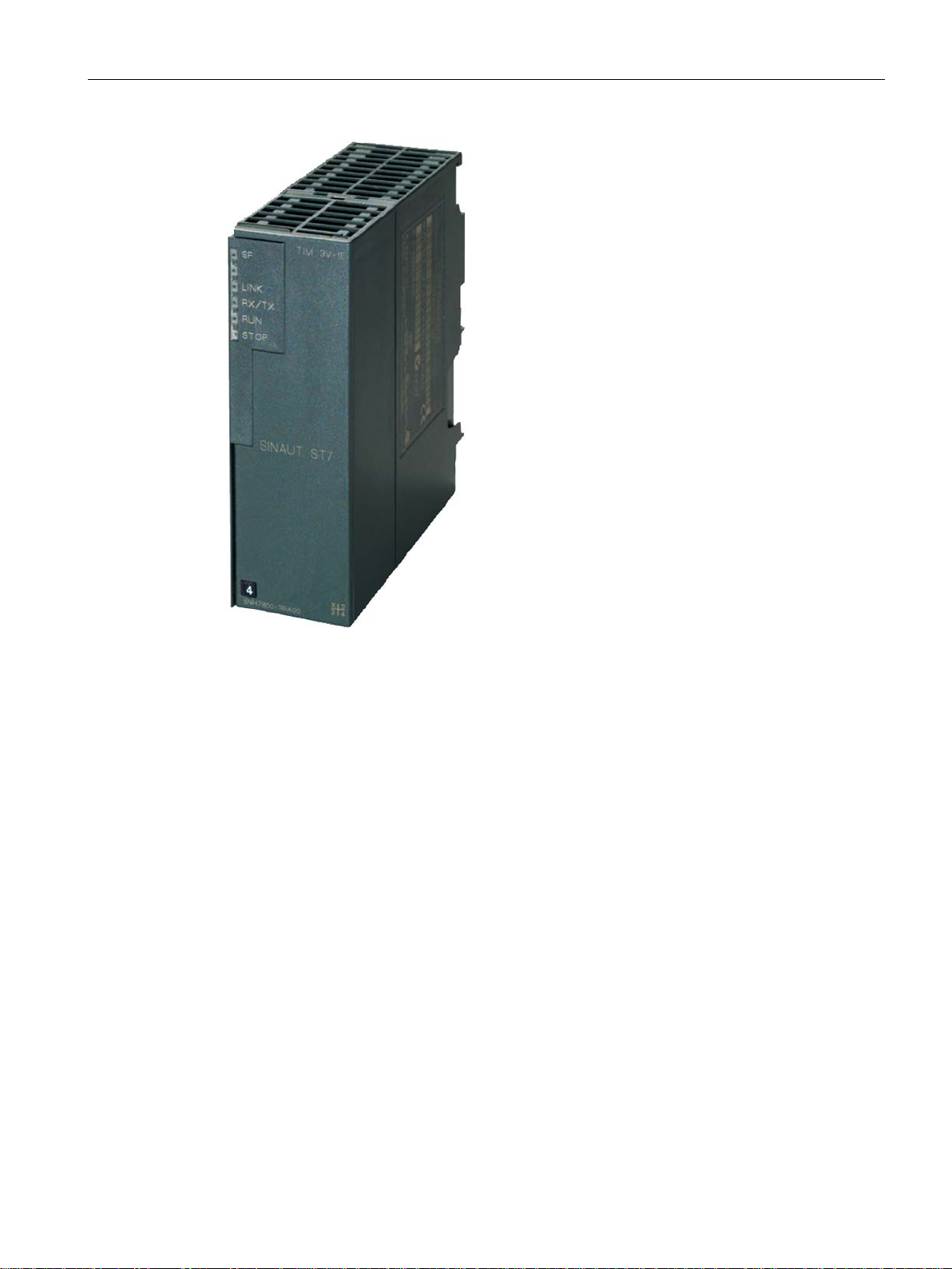
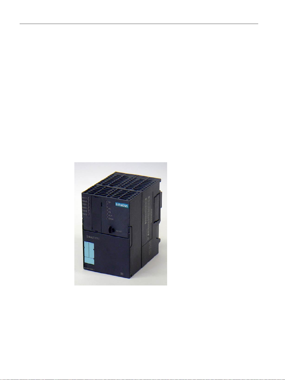
The following figure shows a TIM 3V-IE.
and
RJ-45, also as
SINAUT ST7 station control system
20 System Manual, 09/2016, C79000-G8976-C178-10
Properties of the SINAUT components
1.3 Properties of the TIM modules
Figure 1-1 SINAUT TIM 3V-IE communications module
The TIM 3V-IE variants have all the advantages of the SIMATIC S7-300 system design:
● Compact design; single standard width of the SM modules of the SIMATIC S7-300
● 9-pin D-sub male connector with an RS-232 interface for connecting a modem
● RJ-45 jack for connection to Ethernet; industrial design with additional collar for inserting
the IE FC RJ-45 Plug 180
● 2-pin plug-in terminal block for connecting the external supply voltage of 24 VDC
● Front LEDs for display of Ethernet and WAN communication
● Easy to mount; the TIM is mounted on the S7-300 rail and connected to adjacent
modules by means of the bus connectors. No slot rules apply.
● In conjunction with the IM 360/361 can also be operated in the expansion rack (ER). This
allows the TIM to be combined with a C7 control system, with the newer C7 control
systems it can also be combined using the supplied I/O expansion cable.
● Can be operated without a fan
● A backup battery or memory module are not required
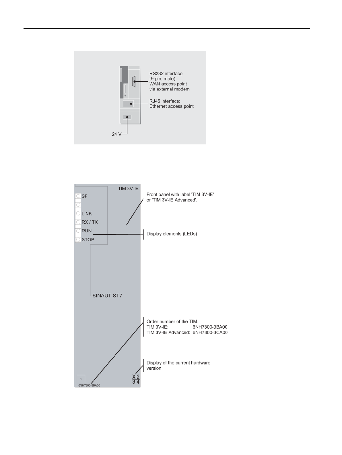
The following figure shows the connectors of the TIM 3V-IE or TIM 3V-IE Advanced
(schematic representation with covers removed).
SINAUT ST7 station control system
System Manual, 09/2016, C79000-G8976-C178-10
21
Properties of the SINAUT components
1.3.2.2
Front view of the TIM 3V-IE variants with closed front panel
1.3 Properties of the TIM modules
Figure 1-2 Connectors of the TIM 3V-IE or TIM 3V-IE Advanced
Figure 1-3 Front view of a TIM 3V-IE variant with closed front panel
SINAUT ST7 station control system
22 System Manual, 09/2016, C79000-G8976-C178-10
Properties of the SINAUT components
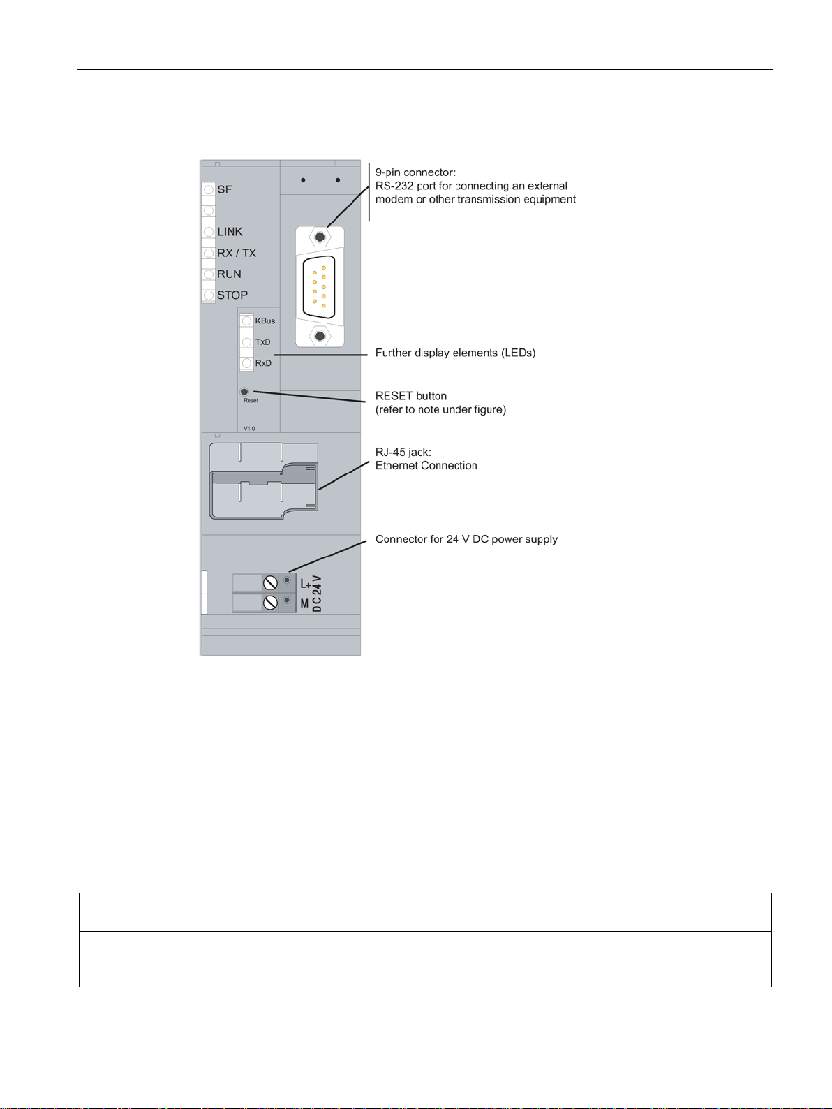
1.3.2.3
Front view of the TIM 3V-IE variants with front panel removed
1.3.2.4
LEDs of the TIM 3V-IE variants
LED no.
Labeling
Relevant TIM interface
Description
Indicates missing or bad parameter settings and RAM errors.
2
none
-
-
1.3 Properties of the TIM modules
Figure 1-4 Front view of a TIM 3V-IE variant with front panel removed
For information on the RESET button, refer to "Default startup" in the section "Startup
activities of the TIM 3V-IE variants".
The following table summarizes the meaning of the nine LEDs during normal operation. The
display during startup is explained in the section "Startup activities of the TIM 3V-IE variants
(Page 133)".
Table 1- 2 Meaning of the LEDs on the front panel of the TIM 3V-IE variants
1 SF all Group error
SINAUT ST7 station control system
System Manual, 09/2016, C79000-G8976-C178-10
23

Properties of the SINAUT components
LED no.
Labeling
Relevant TIM interface
Description
LED is off if there is no physical connection to Ethernet.
LED is off when the module is switched to STOP mode by the PG.
LED is off when the module is switched to RUN mode by the PG
LED no.
Labeling
Relevant TIM interface
Type of WAN
driver
Description
received or sent over MPI / backplane bus.
being sent (TXD).
received (RXD).
off while a telegram is being received (RXD).
1.3 Properties of the TIM modules
3 LINK Ethernet Connection to Ethernet
LED is lit if there is a physical connection to Ethernet.
4 RX/TX Ethernet Data flow over Ethernet
The display changes with each message received or sent via Ethernet.
5 RUN - Module in RUN
LED is lit when the module completes startup without error or is
switched to RUN mode by the PG.
6 STOP - Module in STOP
LED is lit when the module is switched to STOP mode by the PG.
Table 1- 3 Meaning of the LEDs behind the front panel of the TIM 3V-IE variants
7 KBus MPI / K bus - Data flow over MPI / backplane bus
The display state changes with each message
8 TxD RS-232 interface Dedicated line Transmit data
LED is lit constantly and is off while a message is
Dial-up network Transmit data
No connection established:
LED is off.
Connection is established:
LED is lit constantly and is off while a message is
being sent (TXD).
9 RxD RS-232 interface Dedicated line Receive data
As long as receive level (DCD) is detected, the
LED is lit and goes off while a message is being
Dial-up network Receive data
Lights up with an incoming call (RI), remains lit as
long as receive level (DCD) is detected, and goes
SINAUT ST7 station control system
24 System Manual, 09/2016, C79000-G8976-C178-10
Properties of the SINAUT components
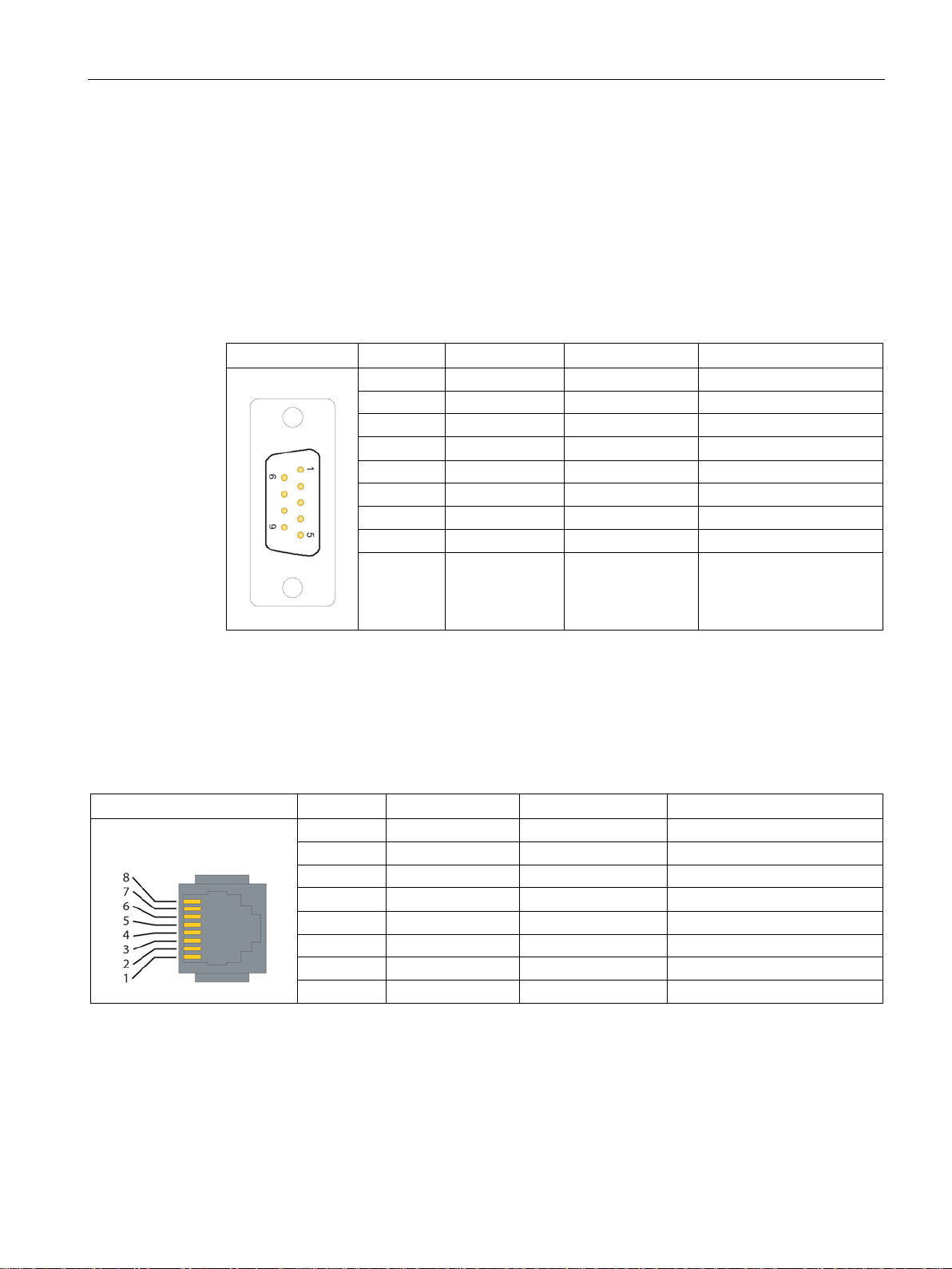
1.3.2.5
Pinout of the ports
RS-232 interface
Illustration
Pin no.
Signal name
Signal direction
Remark
1
DCD
Input
2
RXD
Input
3
TXD
Output
5
GND
6
-
7
RTS
Output
8
CTS
Input
Ethernet port
Illustration
Pin no.
Signal name
Signal direction
Remark
1
TXD+
Output
2
TXD-
Output
3
RXD+
Input
4
-
5
-
6
RXD-
Input
7
-
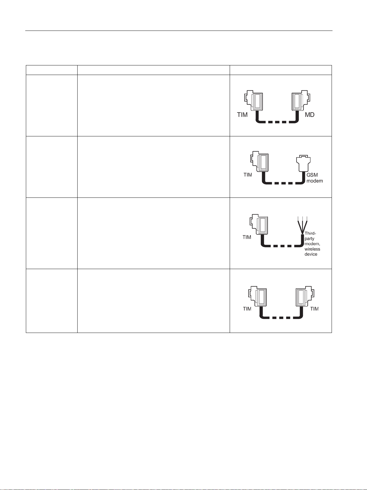
1.3.2.6
Standard connecting cables for the TIM 3V-IE variants
1.3 Properties of the TIM modules
The connector for the RS-232 port is designed as a 9-pin D-sub miniature connector (male).
The pinout is shown in the following table. As an RS-232 port, the pinout corresponds to that
of a standardized PC connector.
Table 1- 4 Pinout of the RS-232 port connector for connecting an external modem
4 DTR Output
9 -
The connector of the Ethernet port is designed as an 8-pin RJ-45 Western jack. The pinout is
shown in the following table.
Table 1- 5 Pinout of the RJ-45 Western jack for the Ethernet port
An external modem or other transmission device can be connected to the 9-pin connector of
the RS-232 port.
To connect to this connector, the following standard connecting cables are available.
8 -
SINAUT ST7 station control system
System Manual, 09/2016, C79000-G8976-C178-10
25
Properties of the SINAUT components
Order no.
Description
Illustration
1.3 Properties of the TIM modules
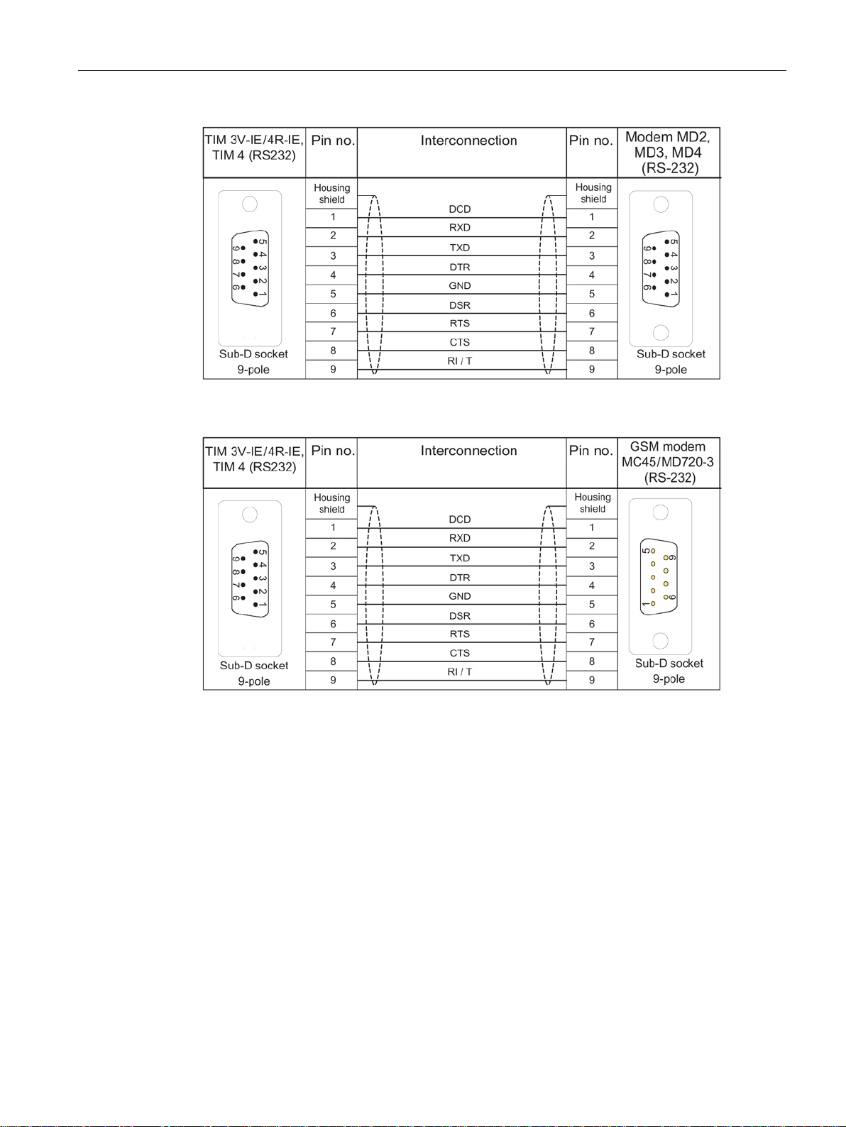
Table 1- 6 Standard connecting cables for the RS-232 port of the TIM 3V-IE variants
6NH7701-4AL Cable for connecting the TIM 3V-IE (RS-232) to one of the
SINAUT ST7 modems MD2, MD3 or MD4 (RS-232).
Also suitable for linking these modems to a SIMATIC pointto-point CP such as the CP 340, CP 341 or CP 441 with
RS-232 interface.
Cable length 1.5 m
6NH7701-5AN Cable for connecting the TIM (RS-232) to the GSM modem
MD720-3 (RS-232). Also suitable for third-party modems or
wireless devices with RS-232 standard.
Cable length 2.5 m.
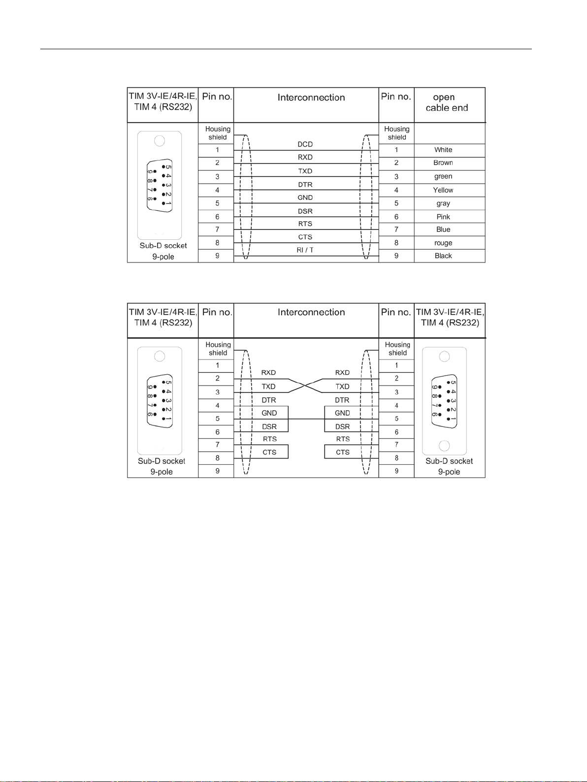
6NH7701-4BN Cable with one end without connector for connecting the
TIM (RS-232) to a third-party modem or wireless device
(RS-232)
Cable length 2.5 m
6NH7701-0AR Test cable.
Cable for connecting two TIM 3V-IE / TIM 4 / TIM 4R-IE
modules over their RS-232 ports without modems (null
modem).
Cable length 6 m
The following figures show the assembly of the connecting cables.
SINAUT ST7 station control system
26 System Manual, 09/2016, C79000-G8976-C178-10
Properties of the SINAUT components
1.3 Properties of the TIM modules
Figure 1-5 Assembly of the standard connecting cable 6NH7701-4AL
Figure 1-6 Assembly of the standard connecting cable 6NH7701-5AN
SINAUT ST7 station control system
System Manual, 09/2016, C79000-G8976-C178-10
27
Properties of the SINAUT components
Connecting cables for connecting to Ethernet
1.3 Properties of the TIM modules
Figure 1-7 Assembly of the standard connecting cable 6NH7701-4BN
Figure 1-8 Assembly of the standard connecting cable 6NH7701-0AR
There is no standard connecting cable available in the SINAUT range to connect the
TIM 4R-IE to Ethernet. Use the suitable Ethernet connecting cables (for example
IE TP Cord) from the SIMATIC NET product range (catalog IK PI).
If a TIM 4R IE is connected to a hub, switch or router, it is advisable to use fully shielded
straight-through patch cables with RJ-45 connectors and 1:1 pin assignment. The cable must
be suitable for the 10Base-TX or 100Base-TX specification.
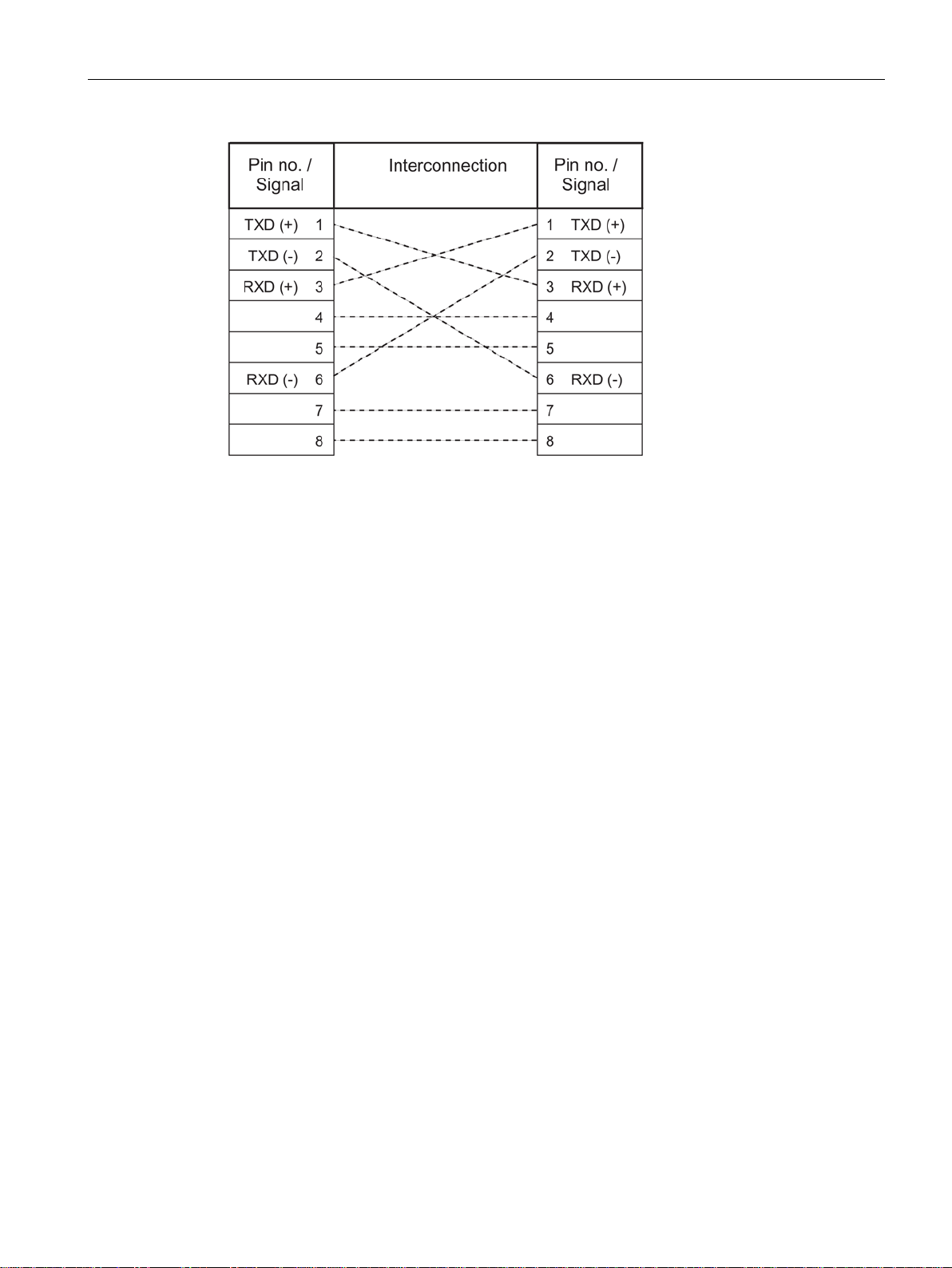
Two Ethernet TIMs (TIM 4R-IE, TIM 3V-IE variant) can also be connected over Ethernet as a
point-to-point link using a crossover patch cable with RJ-45 connectors at both ends and the
following pinout:
SINAUT ST7 station control system
28 System Manual, 09/2016, C79000-G8976-C178-10
Properties of the SINAUT components
1.3.3
TIM 4R-IE
1.3.3.1
The TIM 4R-IE
1.3 Properties of the TIM modules
Figure 1-9 Pinout of a crossover Ethernet RJ-45 cable
The cable must be suitable for the 10Base-TX or 100Base-TX specification.
● TIM without integrated modem, double width
● Has four interfaces:
– 2 x combined RS-232/RS-485 interface for connection of required WAN transmission
equipment (classic SINAUT WAN)
To allow use of GPRS, the switchable serial interface WAN 1 of the TIM 4R-IE can be
connected to a GSM network via the GSM modem MD720-3. This requires the MSC
protocol to be enabled in the STEP 7 > Properties dialog of the TIM > Interfaces tab.
The WAN interface then behaves like an Ethernet interface.
– 2 x RJ-45 interface for attachment to Ethernet
● Compact unit that can be used in a wide variety of situations:
– as a communications processor (CP) in an S7-300
– as a standalone device combined with one or more S7-400s or control center PCs
(SINAUT ST7cc or ST7sc) over the Ethernet interface
● This allows these devices to handle SINAUT communication:
– Over any two classic SINAUT WAN networks with SINAUT partners
– Over two IP-based networks (WAN or LAN) with SINAUT ST7 subscribers
● All four interfaces can be used at the same time for SINAUT communication.
SINAUT ST7 station control system
System Manual, 09/2016, C79000-G8976-C178-10
29
Properties of the SINAUT components
1.3.3.2
Design of the TIM 4R-IE
1.3 Properties of the TIM modules
● The four transmission paths can all be different and operated independently. The two
pairs of interfaces can also form a redundant transmission path.
● When installed as a CP in an S7-300, the following communication is also possible:
– With the CPU
– Over the MPI interface of this CPU with other CPUs and control center PCs (ST7cc,
ST7sc) connected over the MPI bus
– With other TIMs in this rack
● Message memory for up to 56,000 data messages
● Optional backup battery for backup of the stored data messages and the hardware clock
● Up to 62 S7 connections
● The SINAUT TD7 software is integrated on the TIM (TD7onTIM). It can be used when the
TIM is installed as a CP in an S7-300.
● Modules can be replaced without a PG:
– In standalone mode using the optional C-PLUG
– When installed as a CP in an S7-300 over the MMC of the CPU
Figure 1-10 The SINAUT communications module TIM 4R-IE
SINAUT ST7 station control system
30 System Manual, 09/2016, C79000-G8976-C178-10
The TIM 4R-IE variants have all the advantages of the SIMATIC S7-300 system design:
● Compact design; double standard width of the SM modules of the SIMATIC S7-300
● 9-pin D-sub male connector with a combined RS-232/RS-485 interface for connecting a
modem
 Loading...