

Siemens SIMATIC NET TeleControl S7-1200 CP 1243-1 Operating Instructions Manual

___________________
___________________
___________________
___________________
___________________
___________________
___________________
___________________
___________________
___________________
SIMATIC NET
S7-1200 - TeleControl
CP 1243-1
Operating Instructions
12/2016
C79000
Preface
Application and properties
1
LEDs and connectors
2
Installation, connecting up,
commissioning
3
Configuration
4
Diagnostics and upkeep
5
Technical data
6
Approvals
A
Dimension drawings
B
Documentation references
C
-G8976-C365-02

Siemens AG
Division Process Industries and Drives
Postfach 48 48
90026 NÜRNBERG
GERMANY
C79000-G8976-C365-02
Ⓟ
Copyright © Siemens AG 2014 - 2016.
All rights reserved
Legal information
Warning notice system
DANGER
indicates that death or severe personal injury will result if proper precautions are not taken.
WARNING
indicates that death or severe personal injury may result if proper precautions are not taken.
CAUTION
indicates that minor personal injury can result if proper precautions are not taken.
NOTICE
indicates that property damage can result if proper precautions are not taken.
Qualified Personnel
personnel qualified
Proper use of Siemens products
WARNING
Siemens products may only be used for the applications described in the catalog and in the relevant technical
maintenance are required to ensure that the products operate safely and without any problems. The permissible
ambient conditions must be complied with. The information in the relevant documentation must be observed.
Trademarks
Disclaimer of Liability
This manual contains notices you have to observe in order to ensure your personal safety, as well as to prevent
damage to property. The notices referring to your personal safety are highlighted in the manual by a safety alert
symbol, notices referring only to property damage have no safety alert symbol. These notices shown below are
graded according to the degree of danger.
If more than one degree of danger is present, the warning notice representing the highest degree of danger will
be used. A notice warning of injury to persons with a safety alert symbol may also include a warning relating to
property damage.
The product/system described in this documentation may be operated only by
task in accordance with the relevant documentation, in particular its warning notices and safety instructions.
Qualified personnel are those who, based on their training and experience, are capable of identifying risks and
avoiding potential hazards when working with these products/systems.
Note the following:
documentation. If products and components from other manufacturers are used, these must be recommended
or approved by Siemens. Proper transport, storage, installation, assembly, commissioning, operation and
All names identified by ® are registered trademarks of Siemens AG. The remaining trademarks in this publication
may be trademarks whose use by third parties for their own purposes could violate the rights of the owner.
We have reviewed the contents of this publication to ensure consistency with the hardware and software
described. Since variance cannot be precluded entirely, we cannot guarantee full consistency. However, the
information in this publication is reviewed regularly and any necessary corrections are included in subsequent
editions.
for the specific
12/2016 Subject to change
Preface
Validity of this manual
CP 1243-1
This document contains information on the following telecontrol product:
●
Article number 6GK7 243-1BX30-0XE0
Hardware product version 2
Firmware version V2.1.77
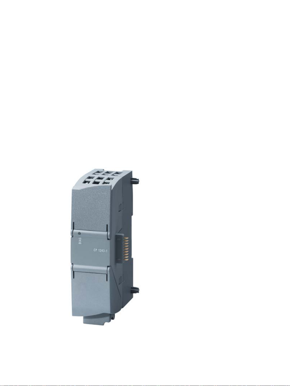
The CP 1243-1 is the communications processor for connecting the SIMATIC S7-1200 to
a control center with TeleControl Server Basic (V3) via the public infrastructure (e.g.
DSL).
With the help of VPN technology and the firewall, the CP allows protected access to the
S7-1200.
The CP can also be used as an additional interface of the CPU for S7 communication.
CP 1243-1
Operating Instructions, 12/2016, C79000-G8976-C365-02
Figure 1 CP 1243-1
3

Preface
Product names and abbreviations
TCSB
STEP 7
ES
Purpose of the manual
New in this issue
Replaced manual issue
Behind the top hinged cover of the module housing, you will see the hardware product
version to the right of the article number printed as a placeholder "X". If the printed text is, for
example, "X 2 3 4", "X" would be the placeholder for hardware product version 1.
You will find the firmware version of the CP as supplied behind the top hinged cover of the
housing to the left below the LED field.
You will find the MAC address under the lower hinged cover of the housing.
● CP
The term "CP" is used below instead of the full product name CP 1243-1.
●
This abbreviation ill be used below for the "TeleControl Server Basic", version V3.
●
This short form will be used below for the STEP 7 Basic / Professional configuration tool.
●
PC with the STEP 7 project
This manual describes the properties of this module and supports you when installing and
commissioning it.
The required configuration steps are described as an overview and there are explanations of
the relationship between firmware functions and configuration.
You will also find information about the diagnostics options of the device.
● New functions in the firmware version named above:
– Changed behavior during time-of-day synchronization, see section Time-of-day
– Changed selection of supported data types, see section Datapoint types (Page 71).
– Changing the IP address during runtime, see section Address and authentication data
– Support of S7 routing
● Functional improvement of data point configuration as of STEP 7 V13 + SP1. see section
Configuring data points and messages (Page 65).
synchronization (Page 50).
(Page 37).
● Editorial revision
Release 07/2014
CP 1243-1
4 Operating Instructions, 12/2016, C79000-G8976-C365-02

Preface
Current manual release on the Internet
Required experience
Cross references
Sources of information and other documentation
License conditions
Note
Open source software
The product contains open source software. Read the license conditions for open sourc
software carefully before using the product.
Firmware
Security information
You will find the current version of this manual on the Internet pages of Siemens Industry
Online Support:
Link: (https://support.industry.siemens.com/cs/ww/en/ps/15922/man)
To install, commission and operate the CP, you require experience in the following areas:
● Automation engineering
● Setting up the SIMATIC S7-1200
● SIMATIC STEP 7 Basic / Professional
In this manual there are often cross references to other sections.
To be able to return to the initial page after jumping to a cross reference, some PDF readers
support the command <Alt>+<Left arrow>.
You will find an overview of further reading and references in the Appendix of this manual.
You will find license conditions in the following document on the supplied data medium:
● OSS-CP1243-1_86.pdf
The firmware is signed and encrypted. This ensures that only firmware created by Siemens
can be downloaded to the device.
e
Siemens provides products and solutions with industrial security functions that support the
secure operation of plants, systems, machines and networks.
CP 1243-1
Operating Instructions, 12/2016, C79000-G8976-C365-02
5

Preface
SIMATIC NET glossary
Training, Service & Support
Recycling and disposal
In order to protect plants, systems, machines and networks against cyber threats, it is
necessary to implement – and continuously maintain – a holistic, state-of-the-art industrial
security concept. Siemens’ products and solutions only form one element of such a concept.
Customer is responsible to prevent unauthorized access to its plants, systems, machines
and networks. Systems, machines and components should only be connected to the
enterprise network or the internet if and to the extent necessary and with appropriate security
measures (e.g. use of firewalls and network segmentation) in place.
Additionally, Siemens’ guidance on appropriate security measures should be taken into
account. For more information about industrial security, please visit
Link: (http://www.siemens.com/industrialsecurity)
Siemens’ products and solutions undergo continuous development to make them more
secure. Siemens strongly recommends to apply product updates as soon as available and to
always use the latest product versions. Use of product versions that are no longer supported,
and failure to apply latest updates may increase customer’s exposure to cyber threats.
To stay informed about product updates, subscribe to the Siemens Industrial Security RSS
Feed under
Link: (http://www.siemens.com/industrialsecurity).
Explanations of many of the specialist terms used in this documentation can be found in the
SIMATIC NET glossary.
You will find the SIMATIC NET glossary on the Internet at the following address:
Link: (https://support.industry.siemens.com/cs/ww/en/view/50305045)
You will find information on Training, Service & Support in the multi--language document
"DC_support_99.pdf" on the data medium supplied with the documentation.
The product is low in pollutants, can be recycled and meets the requirements of the WEEE
directive 2012/19/EU "Waste Electrical and Electronic Equipment".
Do not dispose of the product at public disposal sites. For environmentally friendly recycling
and the disposal of your old device contact a certified disposal company for electronic scrap
or your Siemens contact.
Keep to the local regulations.
You will find information on returning the product on the Internet pages of Siemens Industry
Online Support:
Link: (https://support.industry.siemens.com/cs/ww/en/view/109479891)
CP 1243-1
6 Operating Instructions, 12/2016, C79000-G8976-C365-02

Table of contents
Preface ................................................................................................................................................... 3
1 Application and properties ..................................................................................................................... 11
2 LEDs and connectors ............................................................................................................................ 21
3 Installation, connecting up, commissioning ............................................................................................ 27
4 Configuration ........................................................................................................................................ 33
1.1 Properties of the CP ................................................................................................................ 11
1.2 Communications services ....................................................................................................... 11
1.3 Other services and properties ................................................................................................. 12
1.4 Industrial Ethernet Security ..................................................................................................... 13
1.5 Configuration limits and performance data ............................................................................. 15
1.6 Configuration examples .......................................................................................................... 17
1.7 Requirements for use.............................................................................................................. 18
1.7.1 Hardware requirements .......................................................................................................... 18
1.7.2 Software requirements ............................................................................................................ 19
2.1 Opening the covers of the housing ......................................................................................... 21
2.2 LEDs ....................................................................................................................................... 22
2.3 Electrical connectors ............................................................................................................... 25
2.3.1 Power supply .......................................................................................................................... 25
2.3.2 Ethernet interface X1P1 .......................................................................................................... 25
3.1 Important notes on using the device ....................................................................................... 27
3.1.1 Notices on use in hazardous areas ........................................................................................ 27
3.1.2 Notices on use in hazardous areas according to IECEx / ATEX ............................................ 28
3.1.3 Notices regarding use in hazardous areas according to UL HazLoc ..................................... 29
3.1.4 Notices on use in hazardous areas according to FM ............................................................. 29
3.2 Installing, connecting up and commissioning ......................................................................... 30
3.3 Note on operation ................................................................................................................... 32
4.1 Security recommendations ..................................................................................................... 33
4.2 Configuration in STEP 7 ......................................................................................................... 36
4.3 Address and authentication data ............................................................................................ 37
4.4 Communication types ............................................................................................................. 39
4.5 Ethernet interface (X1) > Advanced options ........................................................................... 39
4.6 SNMP ...................................................................................................................................... 42
4.7 Partner stations ....................................................................................................................... 42
4.7.1 Partner stations > Telecontrol server ...................................................................................... 42
CP 1243-1
Operating Instructions, 12/2016, C79000-G8976-C365-02
7

Table of contents
5 Diagnostics and upkeep ........................................................................................................................ 91
4.7.2 Addressing in the redundant TCSB system ........................................................................... 45
4.7.3 Partner for inter-station communication ................................................................................. 45
4.8 Security .................................................................................................................................. 47
4.8.1 Parameter overview ............................................................................................................... 47
4.8.2 CP identification ..................................................................................................................... 48
4.8.3 Firewall ................................................................................................................................... 49
4.8.3.1 Pre-check of messages by the MAC firewall. ........................................................................ 49
4.8.3.2 Notation for the source IP address (advanced firewall mode) ............................................... 49
4.8.3.3 Firewall settings for configured connection connections via a VPN tunnel ........................... 49
4.8.3.4 Settings for online security diagnostics and downloading to station with the firewall
activated ................................................................................................................................. 49
4.8.4 Time-of-day synchronization .................................................................................................. 50
4.8.5 E-mail configuration ............................................................................................................... 53
4.8.6 Log settings - Filtering of the system events ......................................................................... 54
4.8.7 SNMP ..................................................................................................................................... 54
4.8.8 Certificate manager ................................................................................................................ 55
4.8.9 Handling certificates ............................................................................................................... 56
4.8.10 VPN ........................................................................................................................................ 58
4.8.10.1 VPN (Virtual Private Network) ................................................................................................ 58
4.8.10.2 Creating a VPN tunnel for S7 communication between stations ........................................... 59
4.8.10.3 VPN communication with SOFTNET Security Client (engineering station) ........................... 61
4.8.10.4 Creating the VPN connection telecontrol server .................................................................... 62
4.8.10.5 Establishment of VPN tunnel communication between the CP and SCALANCE M ............. 62
4.8.10.6 CP as passive subscriber of VPN connections ...................................................................... 63
4.8.10.7 SYSLOG ................................................................................................................................ 63
4.8.11 Configuration of the TeleService access ............................................................................... 63
4.9 Data points ............................................................................................................................. 65
4.9.1 Configuring data points and messages ................................................................................. 65
4.9.2 Syntax of the data point names ............................................................................................. 71
4.9.3 Datapoint types ...................................................................................................................... 71
4.9.4 Status IDs of data points ........................................................................................................ 72
4.9.5 Data point index ..................................................................................................................... 73
4.9.6 Read cycle ............................................................................................................................. 74
4.9.7 Process image, type of transmission, event classes, triggers ............................................... 75
4.9.8 "Trigger“ tab ........................................................................................................................... 78
4.9.9 Threshold value trigger ................................................................
.......................................... 79
4.9.10 Analog value preprocessing ................................................................................................... 81
4.9.11 Partner stations: Configuring the inter-station communication .............................................. 87
4.10 Messages ............................................................................................................................... 88
4.11 Access to the Web server ...................................................................................................... 90
5.1 Diagnostics options ................................................................................................................ 91
5.2 Online security diagnostics via port 8448 .............................................................................. 92
5.3 Online functions and TeleService .......................................................................................... 93
5.4 SNMP ..................................................................................................................................... 94
5.5 Processing status of e-mails .................................................................................................. 96
5.6 Downloading firmware ........................................................................................................... 98
CP 1243-1
8 Operating Instructions, 12/2016, C79000-G8976-C365-02

Table of contents
6 Technical data .................................................................................................................................... 101
A Approvals ............................................................................................................................................ 103
B Dimension drawings ............................................................................................................................ 107
C Documentation references .................................................................................................................. 109
Index................................................................................................................................................... 111
5.7 Module replacement ............................................................................................................. 100
6.1 Technical specifications of the CP 1243-1............................................................................ 101
6.2 Pinout of the Ethernet interface ............................................................................................ 102
CP 1243-1
Operating Instructions, 12/2016, C79000-G8976-C365-02
9

Table of contents
CP 1243-1
10 Operating Instructions, 12/2016, C79000-G8976-C365-02

1
1.1
Properties of the CP
Application
1.2
Communications services
Communications services
Telecontrol communication
S7 communication and PG/OP communication with the following functions:
The CP is intended for operation in an S7-1200 automation system. The CP allows
connection of the S7-1200 to Industrial Ethernet or via the Internet to a control center with
TELECONTROL SERVER BASIC (TCSB version V3).
With the combination of different security functions such as firewall and protocols for data
encryption, the CP protects the station and even entire automation cells from unauthorized
access and protects the communication between the remote S7 station and the master
station (TCSB) from espionage and manipulation.
The following communications services are supported:
●
The CP is a communications processor of the SIMATIC S7-1200 for system connection to
control centers with the OPC server application TCSB.
The communications protocol used allows IP-based data transmission for telecontrol
applications. As an integrated (unconfigurable) Security function, the telecontrol protocol
encrypts the data for transfer between the CP and telecontrol server.
For a description of the configurable Security functions, refer to the section Industrial
Ethernet Security (Page 13).
●
– PUT/GET as client and server for data exchange with remote stations (S7-
300/400/1200/1500)
– PG functions
– Operator control and monitoring functions (HMI)
CP 1243-1
Operating Instructions, 12/2016, C79000-G8976-C365-02
11

Application and properties
1.3
Other services and properties
Other services and properties
Data point configuration
IP configuration - IPv4 and IPv6
Time-of-day synchronization
Redundancy
Storage of events
Data transfer is on request or triggered
1.3 Other services and properties
●
Due to the data point configuration in STEP 7, programming program blocks in order to
transfer the process data is unnecessary. The individual data points are processed oneto-one in the control system.
●
– IPv4 / IPv6
The CP supports IP addresses according to IPv4 and IPv6.
For telecontrol applications in IPv6 networks, an IPv6 address can be used in addition
to an IPv4 address.
– Address assignment
The IP address, the subnet mask and the address of a gateway can be set manually
in the configuration.
As an alternative, the IP address can be obtained from a DHCP server or by other
means outside the configuration.
●
– When telecontrol communication is enabled, the CP obtains its local time of day as
UTC time from the partner (TCSB). The time of day can be read from the CPU. The
mechanisms are described in the STEP 7 information system.
For information on the format of the time stamp, refer to the section Datapoint types
(Page 71).
– If telecontrol communication is disabled, the time of day can be obtained from an NTP
server or from the CPU.
– If the security functions are enabled, the secure method NTP (secure) can be used.
For more information, refer to the section Time-of-day synchronization (Page 50).
●
The CP can communicate with a redundant installation of TCSB.
●
The CP can store events of different classes chronologically and transfer them
spontaneously or together to the telecontrol server.
●
The telecontrol communication with TCSB is triggered in two ways:
– After a request by TCSB or an OPC client connected to TCSB
– Triggered by various selectable criteria
CP 1243-1
12 Operating Instructions, 12/2016, C79000-G8976-C365-02

Application and properties
Messages / e-mail
Analog value processing
Online functions / TeleService
SNMP
1.4
Industrial Ethernet Security
Industrial Ethernet Security
1.4 Industrial Ethernet Security
●
With configured events in the process image of the CPU, the CP can send messages as
e-mails. The data sent by e-mail is configured using PLC tags.
●
Analog values can be preprocessed on the CP according to various methods.
●
From the engineering station you can access the station via the CP with the online
functions of STEP 7.
The following online functions are available:
– Downloading project or program data from the STEP 7 project to the station
– Querying diagnostics data on the station
– Downloading firmware files to the CP
For information on the online functions, refer to the section Online functions and
TeleService (Page 93).
●
As an SNMP agent, the CP supports data queries using SNMP (Simple Network
Management Protocol).
For more detailed information, refer to section SNMP (Page 94).
With Industrial Ethernet Security, individual devices, automation cells or network segments
of an Ethernet network can be protected. The data transfer via the CP can be protected from
the following attacks by a combination of different security measures:
● Data espionage
● Data manipulation
● Unauthorized access
Secure underlying networks can be operated via additional Ethernet/PROFINET interfaces of
the CPU.
The security functions can be used independently of telecontrol communication.
CP 1243-1
Operating Instructions, 12/2016, C79000-G8976-C365-02
13

Application and properties
Security functions of the CP
Firewall
Communication made secure by IPsec tunnels (VPN)
Logging
NTP (secure)
SNMPv3
Protection for devices and network segments
Note
Plants with security requirements - recommendation
Use the following options:
•
•
See also section
1.4 Industrial Ethernet Security
As a result of using the CP, as a security module, the following security functions are
accessible to the S7-1200 station on the interface to the external network:
●
– IP firewall with stateful packet inspection (layer 3 and 4)
– Firewall also for "non-IP" Ethernet frames according to IEEE 802.3 (layer 2)
– Limitation of the transmission speed ("Bandwidth limitation")
– Global firewall rules
●
VPN tunnel communication allows the establishment of secure IPsec tunnels for
communication with one or more security modules.
The CP can be put together with other modules to form VPN groups during configuration.
IPsec tunnels (VPN) are created between all security modules of a VPN group. All
internal nodes of these security modules can communicate securely with each other
through these tunnels.
●
To allow monitoring, events can be stored in log files that can be read out using the
configuration tool or can be sent automatically to a Syslog server.
●
For secure transfer during time-of-day synchronization
●
For secure transmission of network analysis information safe from eavesdropping
●
The protection provided by the firewall can cover individual devices, several devices or
even entire network segments.
If you have systems with high security requirements, use the secure protocols
NTP (secure), HTTPS and SNMPv3.
If you connect to public networks, you should use the firewall. Think about the services
you want to allow access to the station via public networks. By using the "bandwidth
limitation" of the firewall, you can restrict the possibility of flooding and DoS attacks.
Security recommendations (Page 33).
For configuring the security functions refer to the section Security (Page 47).
You will find further information on the functionality and configuration of the security functions
in the information system of STEP 7 and in the manual /4/ (Page 110).
CP 1243-1
14 Operating Instructions, 12/2016, C79000-G8976-C365-02

Application and properties
1.5
Configuration limits and performance data
Number of CMs/CPs per station
Connection resources
Telecontrol connections
TCP connections
Online functions
S7 connections
PG/OP connections
Number of data points for the data point configuration
User data
1.5 Configuration limits and performance data
In each S7-1200 station, up to three CMs/CPs can be plugged in and configured; this allows
three CP 1243-1 modules.
To use telecontrol communication, three CP 1243-1 modules can be plugged in per station
that communicate with three telecontrol servers.
●
The CP can establish corrections to non-redundant or redundant telecontrol servers
(TCSB).
In addition to this, inter-station communication with up to 4 S7 stations with a CP 1243-1
can be operated via the telecontrol server.
●
The CP can establish connections to up to 4 communications partners (S7 stations).
●
1 connection resource is reserved for online functions.
●
8 connection resources for S7 connections (PUT/GET)
●
– 1 connection resource for PG connections
– 3 connection resources for OP connections
The maximum number of configurable data points is 200.
The data to be transferred by the CP is assigned to various data points in the STEP 7
configuration.
The size of the user data per data point depends on the data type of the relevant data point.
You will find details in the section Datapoint types (Page 71).
CP 1243-1
Operating Instructions, 12/2016, C79000-G8976-C365-02
15

Application and properties
Frame memory (send buffer)
Messages / e-mail
IPsec tunnel (VPN)
Firewall rules
1.5 Configuration limits and performance data
The CP has a frame memory (send buffer) for the values of data points configured as an
event.
The send buffer has a maximum size of 64000 events divided into equal parts for all
configured communications partners. The size of the frame memory can be set in STEP 7,
refer to the section SNMP (Page 42).
Up to 10 messages can be configured in STEP 7 and sent as e-mails.
Up to 8 IPsec terminals can be established for secure communication with other security
modules.
The maximum number of firewall rules in advanced firewall mode is limited to 256.
The firewall rules are divided up as follows:
● Maximum 226 rules with individual addresses
● Maximum 30 rules with address ranges or network addresses
(e.g. 140.90.120.1 - 140.90.120.20 or 140.90.120.0/16)
● Maximum 128 rules with limitation of the transmission speed ("Bandwidth limitation")
CP 1243-1
16 Operating Instructions, 12/2016, C79000-G8976-C365-02
Application and properties
1.6
Configuration examples
Telecontrol with a non-redundant master station (TCSB)
Communication between S7 stations and a master station (TCSB)
1.6 Configuration examples
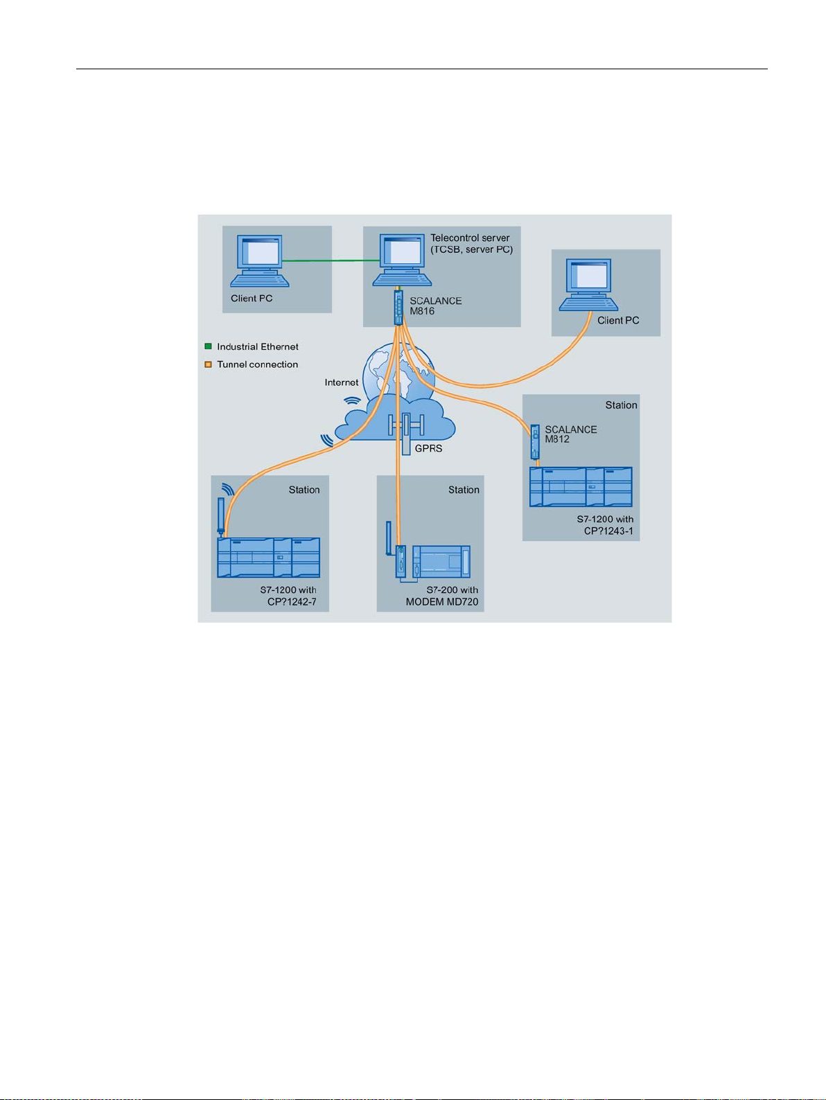
Figure 1-1
In the telecontrol applications of the example shown, SIMATIC S7 stations communicate with
a non-redundant telecontrol server (TCSB) in the master station.
● Telecontrol communication between stations and master station
The communication is via the following paths and communications modules:
– Communication via the Internet: S7-1200 with CP 1243-1
– Communication via the GSM network and the Internet: S7-1200 with CP 1242-7 or
The establishment of terminal connections with encryption is initiated automatically by the
telecontrol protocol used by the various communications modules.
The creation of VPN connections between the CP 1243-1 and telecontrol server is
optional.
The telecontrol server monitors the connections established by the remote stations.
● Inter-station communication
Stations of the same type, for example S7-1200 with CP 1243-1, can communicate with
each other by sending the frames via the telecontrol server.
S7-200 with MODEM MD720
CP 1243-1
Operating Instructions, 12/2016, C79000-G8976-C365-02
17
Application and properties
Telecontrol with a redundant master station (TCSB)
S7 station communication with a redundant a master station
1.7
Requirements for use
1.7.1
Hardware requirements
1.7 Requirements for use
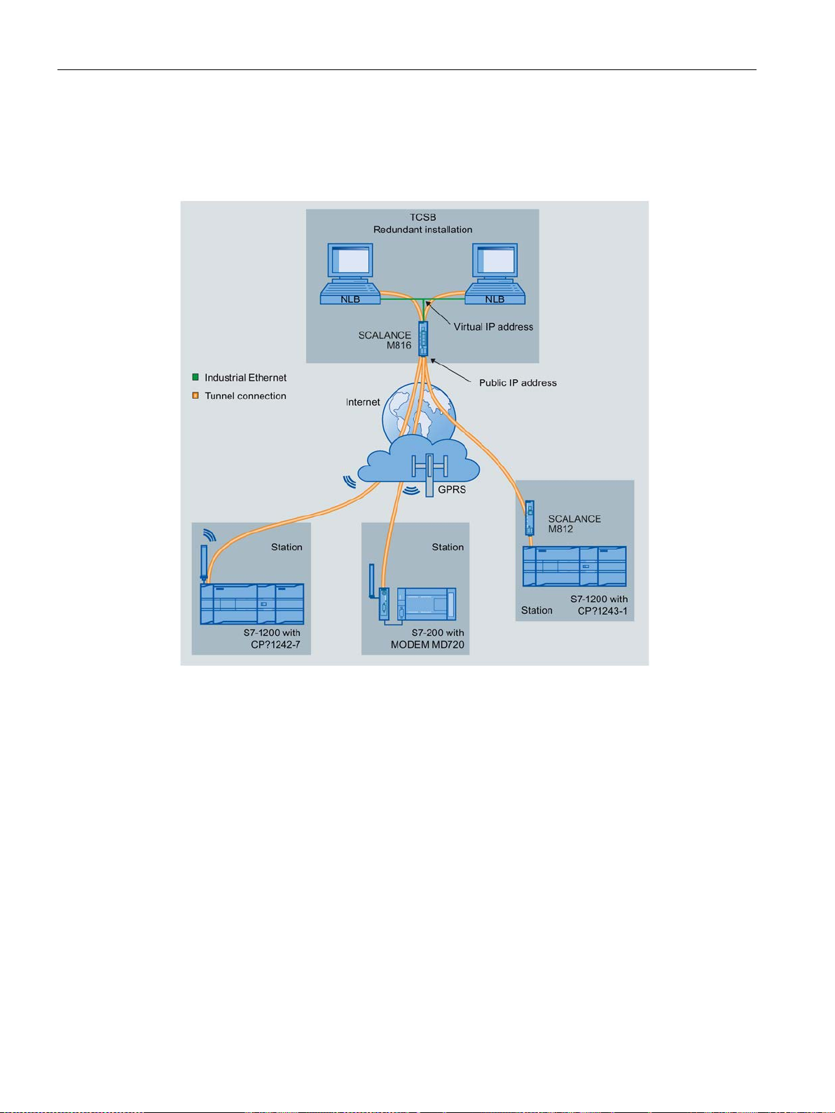
The following figure shows a possible configuration with S7 stations communicating with a
redundant master station (TCSB).
Figure 1-2
CP 1243-1
18 Operating Instructions, 12/2016, C79000-G8976-C365-02
The following description relates to a configuration with telecontrol communication with
TCSB.
Rails, housing, cabling and other accessories are not taken into account.
Depending on the configuration of your plant, you require the following devices and firmware
versions.

Application and properties
Application example: Telecontrol communication with TCSB
In the S7-1200 station:
In the master station:
For the configuration of the S7 station with CP:
1.7.2
Software requirements
Software for configuration and online functions
1.7 Requirements for use
● CPU with firmware version: 4.x
● Mobile wireless router SCALANCE M812
● PC with TCSB (version V3)
● Mobile wireless router SCALANCE M816
For more detailed information on the structure of TCSB , refer to the section /3/ (Page 110).
● When using online functions: Engineering station with STEP 7 (refer to the section
Software requirements (Page 19)).
Engineering station with STEP 7
To configure the CP, the following configuration tool is required:
● STEP 7 Basic / Professional V13.0 with support package 0093
or
● STEP 7 Basic / Professional V13.0 + SP1
To use all the functions of the CP with the firmware version mentioned in the preface, the
following configuration tool is required:
● STEP 7 Basic / Professional V14
CP 1243-1
Operating Instructions, 12/2016, C79000-G8976-C365-02
19

Application and properties
1.7 Requirements for use
CP 1243-1
20 Operating Instructions, 12/2016, C79000-G8976-C365-02
2
2.1
Opening the covers of the housing
Location of the display elements and the electrical connectors
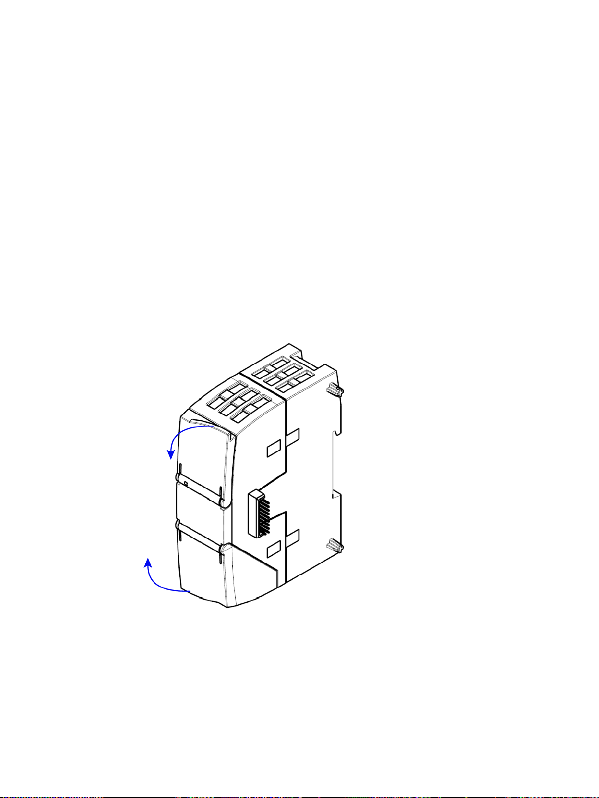
Opening the covers of the housing
The LEDs for the detailed display of the module statuses are located behind the upper cover
of the module housing.
The Ethernet connector is located behind the lower hinged cover of the module.
Open the upper or lower cover of the housing by pulling it down or up as shown by the
arrows in the illustration. The covers extend beyond the housing to give you a grip.
Figure 2-1 Opening the covers of the housing
CP 1243-1
Operating Instructions, 12/2016, C79000-G8976-C365-02
21
LEDs and connectors
2.2
LEDs
LEDs of the module
LED on the front panel
LEDs below the upper cover of the housing
LED on the front panel
LED / colors
Name
Meaning
DIAG
LEDs below the upper cover of the housing
LED (color)
Name
Meaning
(green)
LINK
(green)
CONNECT
(green)
VPN
(green)
SERVICE
LED colors and illustration of the LED statuses
Meaning of the LED symbols
Symbol
LED status
OFF
ON (steady light)
Flashing
Not relevant
Note
LED colors when the module starts up
When the module start
color mixture. At this point in time, the color of the LEDs is not clear.
2.2 LEDs
The module has various LEDs for displaying the status:
●
The "DIAG" LED that is always visible shows the basic statuses of the module.
●
The LEDs below the upper cover provide more detailed information on the module status.
Table 2- 1
(red / green)
Table 2- 2
Basic status of the module
Status of the connection to Industrial Ethernet
Status of the connections to the communications partner
Status of the VPN configuration
Status of a connection for online functions
The LED symbols in the following tables have the following significance:
Table 2- 3
s up, all its LEDs are lit for a short time. Multicolored LEDs display a
CP 1243-1
22 Operating Instructions, 12/2016, C79000-G8976-C365-02
-
LEDs and connectors
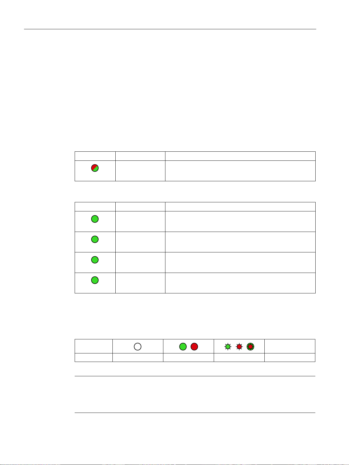
Display of the basic statuses of the CP ("DIAG" LED)
DIAG
(red / green)
Meaning
(if more than one point listed: alternative meaning)
Basic statuses of the CP
green
flashing green
flashing red-green
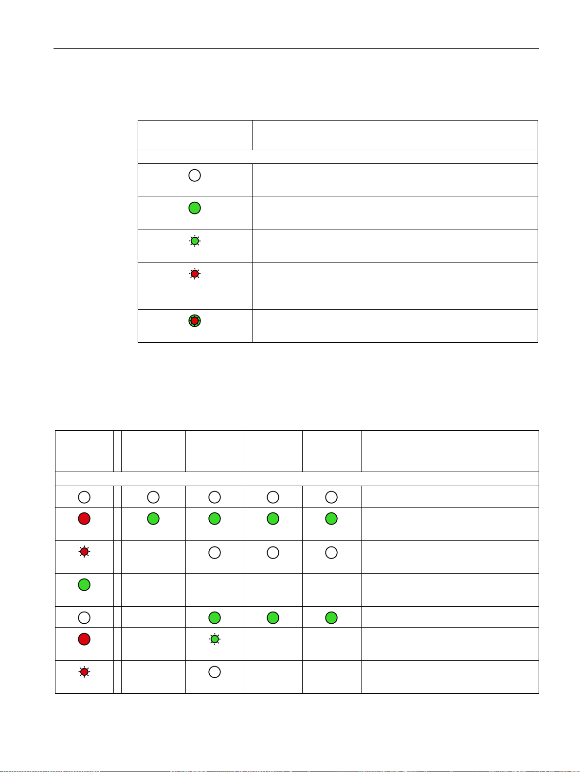
Display of the operating and communications statuses
DIAG
-
LINK
CONNECT
VPN
SERVICE
Meaning
(if more than one point listed: alternative
meaning)
Module startup (STOP → RUN) or error statuses
red
flashing red
green
red
flashing red
2.2 LEDs
Table 2- 4 Display of the basic statuses of the CP
flashing red
• Power OFF
• Incorrect startup
Running (RUN) without serious error
• Partner not connected
• Firmware loaded successfully
• Starting up
• Module fault
• Invalid STEP 7 project data
Error loading firmware
The LEDs indicate the operating and communications status of the module according to the
following scheme:
Table 2- 5 Display of the operating and communications statuses
(red / green)
(green)
(green)
(green)
(green)
-
- - - - Running (RUN) without serious error
-
-
CP 1243-1
Operating Instructions, 12/2016, C79000-G8976-C365-02
Power OFF
Startup - phase 1
Startup - phase 2
Incorrect startup
- - Invalid STEP 7 project data
- - Missing STEP 7 project data
23
LEDs and connectors
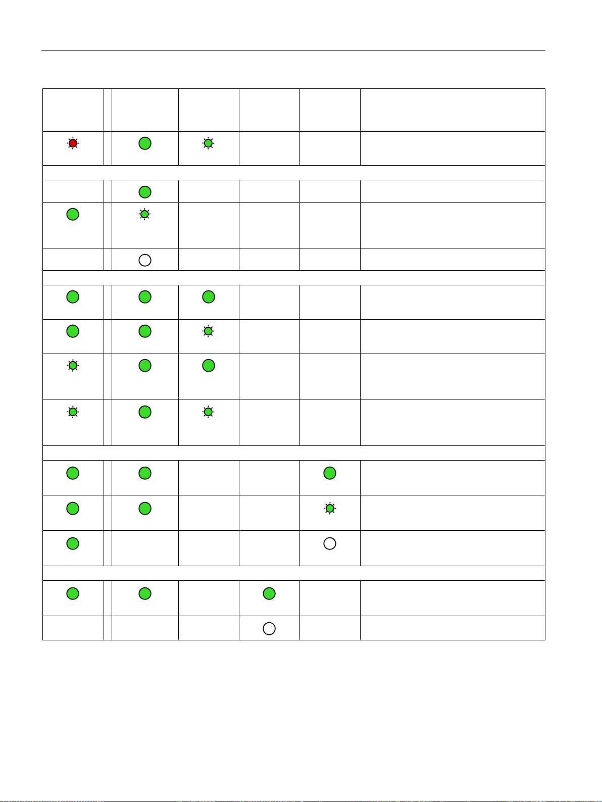
DIAG
-
LINK
CONNECT
VPN
SERVICE
Meaning
(if more than one point listed: alternative
meaning)
flashing red
Connection to Industrial Ethernet
Connection to communications partners
green
green
green
Connection for online functions
green
green
green
VPN connection
green
2.2 LEDs
(red / green)
-
green
-
flashing
(green)
(green)
- - - Connection to Industrial Ethernet exists
- - -
- - - No connection to Industrial Ethernet
(green)
- - Backplane bus error
- - Connection established to at least one
- - Partner reachable, CPU in STOP mode
- - Partner not reachable, CPU in RUN mode
(green)
• Connection to Industrial Ethernet being
established.
• IP address being obtained.
partner
flashing
green
- - -
- - -
- -
- -
-
- - Partner not reachable, CPU in STOP mode
Connection for online functions established
Attempt to establish connection for online
functions
No connection to engineering station
- VPN connection configured on the CP
- No VPN connection configured on the CP
CP 1243-1
24 Operating Instructions, 12/2016, C79000-G8976-C365-02
LEDs and connectors
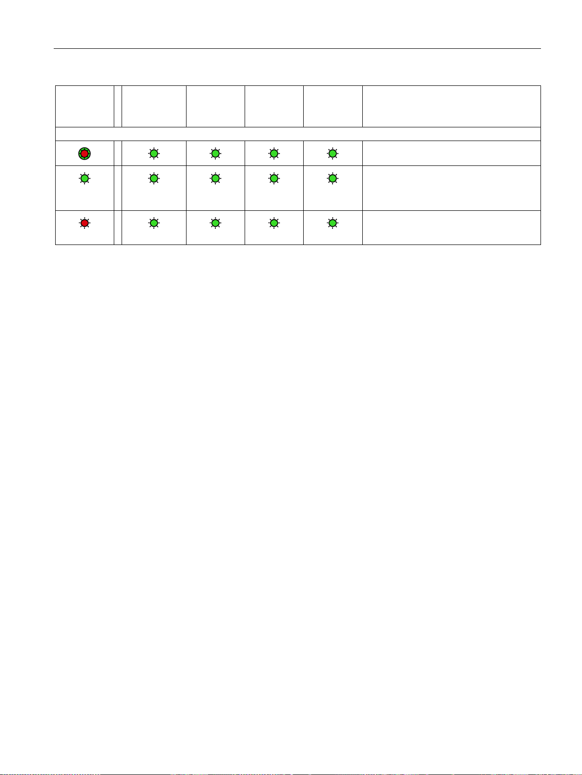
DIAG
-
LINK
CONNECT
VPN
SERVICE
Meaning
(if more than one point listed: alternative
meaning)
Loading firmware
green
flashing red
2.3
Electrical connectors
2.3.1
Power supply
Power supply
2.3.2
Ethernet interface X1P1
Ethernet interface
2.3 Electrical connectors
(red / green)
flashing
(green)
(green)
(green)
(green)
Loading firmware. The DIAG LED flashes
alternating red and green.
Firmware was successfully loaded.
Error loading firmware
The CM is supplied with power from the backplane bus. It does not require a separate power
supply.
The Ethernet connector is located behind the lower hinged cover of the module. The
interface is an RJ-45 jack according to IEEE 802.3.
The pin assignment and other data relating to the Ethernet interface can be found in the
section Technical data (Page 101).
CP 1243-1
Operating Instructions, 12/2016, C79000-G8976-C365-02
25

LEDs and connectors
2.3 Electrical connectors
CP 1243-1
26 Operating Instructions, 12/2016, C79000-G8976-C365-02

3
3.1
Important notes on using the device
Safety notices on the use of the device
Overvoltage protection
NOTICE
Protection of the external power supply
3.1.1
Notices on use in hazardous areas
WARNING
EXPLOSION HAZARD
WARNING
Note the following safety notices when setting up and operating the device and during all
associated work such as installation, connecting up or replacing the device.
If power is supplied to the module or station over longer power cables or networks, the
coupling in of strong electromagnetic pulses onto the power supply cables is possible. This
can be caused, for example by lightning strikes or switching of higher loads.
The connector of the external power supply is not protected from strong electromagnetic
pulses. To protect it, an external overvoltage protection module is necessary. The
requirements of EN61000-4-5, surge immunity tests on power supply lines, are met only
when a suitable protective element is used. A suitable device is, for example, the Dehn
Blitzductor BVT AVD 24, article number 918 422 or a comparable protective element.
Manufacturer:
DEHN+SOEHNE GmbH+Co.KG Hans Dehn Str.1 Postfach 1640 D-92306 Neumarkt,
Germany
DO NOT OPEN WHEN ENERGIZED.
The device may only be operated in an environment with pollution degree 1 or 2 (see IEC
60664-1).
CP 1243-1
Operating Instructions, 12/2016, C79000-G8976-C365-02
27
Installation, connecting up, commissioning
WARNING
WARNING
EXPLOSION HAZARD
WARNING
EXPLOSION HAZARD
WARNING
3.1.2
Notices on use in hazardous areas according to IECEx / ATEX
WARNING
Requirements for the cabinet/enclosure
WARNING
3.1 Important notes on using the device
The equipment is designed for operation with Safety Extra-Low Voltage (SELV) by a
Limited Power Source (LPS).
This means that only SELV / LPS complying with IEC 60950-1 / EN 60950-1 / VDE 0805-1
must be connected to the power supply terminals. The power supply unit for the equipment
power supply must comply with NEC Class 2, as described by the National Electrical Code
(r) (ANSI / NFPA 70).
If the equipment is connected to a redundant power supply (two separate power supplies),
both must meet these requirements.
DO NOT CONNECT OR DISCONNECT EQUIPMENT WHEN A FLAMMABLE OR
COMBUSTIBLE ATMOSPHERE IS PRESENT.
SUBSTITUTION OF COMPONENTS MAY IMPAIR SUITABILITY FOR CLASS I, DIVISION
2 OR ZONE 2.
When used in hazardous environments corresponding to Class I, Division 2 or Class I,
Zone 2, the device must be installed in a cabinet or a suitable enclosure.
To comply with EU Directive 94/9 (ATEX95), the enclosure or cabinet must meet the
requirements of at least IP54 in compliance with EN 60529.
If the cable or conduit entry point exceeds 70 °C or the branching point of conductors
exceeds 80 °C, special precautions must be taken. If the equipment is operated in an air
ambient in excess of 50 °C, only use cables with admitted maximum operating temperature
of at least 80 °C.
CP 1243-1
28 Operating Instructions, 12/2016, C79000-G8976-C365-02

Installation, connecting up, commissioning
WARNING
3.1.3
Notices regarding use in hazardous areas according to UL HazLoc
WARNING
EXPLOSION HAZARD
3.1.4
Notices on use in hazardous areas according to FM
WARNING
EXPLOSION HAZARD
WARNING
EXPLOSION HAZARD
3.1 Important notes on using the device
Take measures to prevent transient voltage surges of more than 40% of the rated voltage.
This is the case if you only operate devices with SELV (safety extra-low voltage).
DO NOT DISCONNECT WHILE CIRCUIT IS LIVE UNLESS AREA IS KNOWN TO BE
NON-HAZARDOUS.
This equipment is suitable for use in Class I, Division 2, Groups A, B, C and D or nonhazardous locations only.
This equipment is suitable for use in Class I, Zone 2, Group IIC or non-hazardous locations
only.
Do not connect or disconnect while the circuit is live or unless the area is known to be free
of ignitible concentrations.
This equipment is suitable for use in Class I, Division 2, Groups A, B, C and D or nonhazardous locations only.
This equipment is suitable for use in Class I, Zone 2, Group IIC or non-hazardous locations
only.
The equipment is intended to be installed within an ultimate enclosure. The inner service
temperature of the enclosure corresponds to the ambient temperature of the module. Use
installation wiring connections with admitted maximum operating temperature of at least
30 ºC higher than maximum ambient temperature.
CP 1243-1
Operating Instructions, 12/2016, C79000-G8976-C365-02
29
Installation, connecting up, commissioning
3.2
Installing, connecting up and commissioning
Prior to installation and commissioning
CAUTION
Read the system manual "S7-1200 Programmable Controller"
Pulling/plugging the module
NOTICE
Turning off the station when plugging/pulling the module
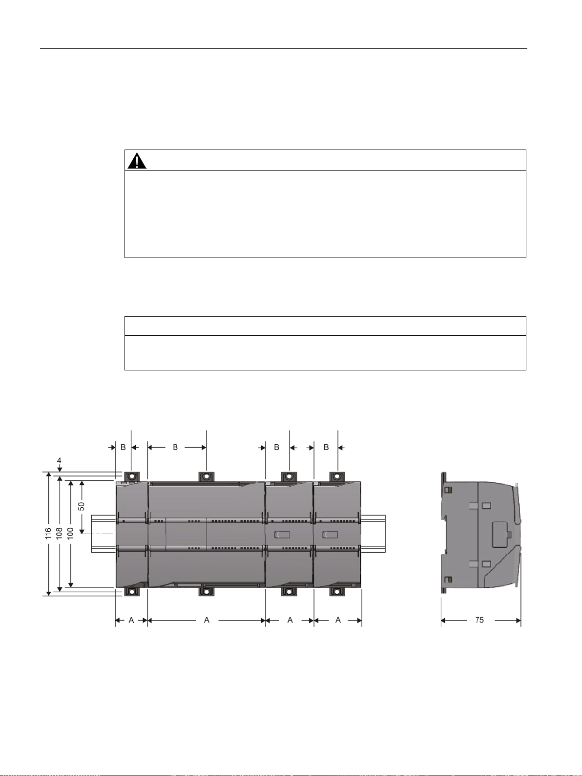
Dimensions for installation
3.2 Installing, connecting up and commissioning
Prior to installation, connecting up and commissioning, read the relevant sections in the
system manual "S7-1200 Programmable Controller", refer to the documentation in the
Appendix.
When installing and connecting up, keep to the procedures described in the system manual
"S7-1200 Programmable Controller".
Before pulling or plugging the module, always turn off the power supply to the station.
Figure 3-1 Dimensions for installation of the S7-1200
CP 1243-1
30 Operating Instructions, 12/2016, C79000-G8976-C365-02
 Loading...