

Siemens SIMATIC NET SCALANCE XM-400 Operating Instructions Manual

___________________
___________________
___________________
___________________
___________________
___________________
___________________
___________________
___________________
___________________
SIMATIC NET
Industrial Ethernet switches
SCALANCE XM-400
Operating Instructions
09/2018
C79000
Introduction
1
Safety notices
2
Recommendations on
network security
3
Description of the device
4
Installation
5
Connecting up
6
Upkeep and maintenance
7
Technical specifications
8
Dimension drawings
9
Approvals
A
-G8976-C306-08

Siemens AG
Division Process Industries and Drives
Postfach 48 48
90026 NÜRNBERG
GERMANY
C79000-G8976-C306-08
Ⓟ
Copyright © Siemens AG 2013 - 2018.
All rights reserved
Legal information
Warning notice system
DANGER
indicates that death or severe personal injury will result if proper precautions are not taken.
WARNING
indicates that death or severe personal injury may result if proper precautions are not taken.
CAUTION
indicates that minor personal injury can result if proper precautions are not taken.
NOTICE
indicates that property damage can result if proper precautions are not taken.
Qualified Personnel
personnel qualified
Proper use of Siemens products
WARNING
Siemens products may only be used for the applications described in the catalog and in the relevant technical
ambient conditions must be complied with. The information in the relevant documentation must be observed.
Trademarks
Disclaimer of Liability
This manual contains notices you have to observe in order to ensure your personal safety, as well as to prevent
damage to property. The notices referring to your personal safety are highlighted in the manual by a safety alert
symbol, notices referring only to property damage have no safety alert symbol. These notices shown below are
graded according to the degree of danger.
If more than one degree of danger is present, the warning notice representing the highest degree of danger will
be used. A notice warning of injury to persons with a safety alert symbol may also include a warning relating to
property damage.
The product/system described in this documentation may be operated only by
task in accordance with the relevant documentation, in particular its warning notices and safety instructions.
Qualified personnel are those who, based on their training and experience, are capable of identifying risks and
avoiding potential hazards when working with these products/systems.
Note the following:
documentation. If products and components from other manufacturers are used, these must be recommended
or approved by Siemens. Proper transport, storage, installation, assembly, commissioning, operation and
maintenance are required to ensure that the products operate safely and without any problems. The permissible
All names identified by ® are registered trademarks of Siemens AG. The remaining trademarks in this publication
may be trademarks whose use by third parties for their own purposes could violate the rights of the owner.
We have reviewed the contents of this publication to ensure consistency with the hardware and software
described. Since variance cannot be precluded entirely, we cannot guarantee full consistency. However, the
information in this publication is reviewed regularly and any necessary corrections are included in subsequent
editions.
for the specific
09/2018 Subject to change

Table of contents
1 Introduction ............................................................................................................................................. 5
2 Safety notices ....................................................................................................................................... 11
3 Recommendations on network security ................................................................................................. 13
4 Description of the device ....................................................................................................................... 19
5 Installation ............................................................................................................................................ 45
4.1 Properties and functions ......................................................................................................... 19
4.2 Product overview .................................................................................................................... 21
4.3 Accessories ............................................................................................................................. 23
4.4 Spare parts ............................................................................................................................. 26
4.5 Device views ........................................................................................................................... 27
4.5.1 SCALANCE XM408-4C .......................................................................................................... 27
4.5.2 SCALANCE XM408-8C .......................................................................................................... 28
4.5.3 SCALANCE XM416-4C .......................................................................................................... 29
4.6 SELECT / SET button ............................................................................................................. 30
4.7 LED display ............................................................................................................................. 32
4.7.1 Overview ................................................................................................................................. 32
4.7.2 "RM" LED ................................................................................................................................ 33
4.7.3 "SB" LED ................................................................................................................................. 33
4.7.4 "F" LED ................................................................................................................................... 34
4.7.5 LEDs "DM1" and "DM2" .......................................................................................................... 34
4.7.6 LEDs "L1" and "L2" ................................................................................................................. 35
4.7.7 Port LEDs ................................................................................................................................ 36
4.8 C-PLUG/KEY-PLUG ............................................................................................................... 39
4.8.1 Function of the C-PLUG/KEY-PLUG ...................................................................................... 39
4.8.2 Replacing the C-PLUG/KEY-PLUG ........................................................................................ 40
4.9 Functions ................................................................................................................................ 42
4.9.1 Combo ports ........................................................................................................................... 42
4.9.2 Power over Ethernet (PoE) .....................................................................................................
4.9.3 Near Field Communication ..................................................................................................... 44
5.1 Safety notices for installation .................................................................................................. 45
5.2 Types of installation ................................................................................................................ 47
5.3 Mounting on DIN rails ............................................................................................................. 48
5.4 Installation on a standard S7-300 rail ..................................................................................... 49
43
5.5 Installation on a standard S7-1500 rail ................................................................................... 50
5.6 Fitting an extender .................................................................................................................. 51
5.7 General notes for SFP transceivers ........................................................................................ 54
SCALANCE XM-400
Operating Instructions, 09/2018, C79000-G8976-C306-08
3

Table of contents
6 Connecting up....................................................................................................................................... 55
7 Upkeep and maintenance ..................................................................................................................... 65
8 Technical specifications ........................................................................................................................ 67
9 Dimension drawings .............................................................................................................................. 73
A Approvals ............................................................................................................................................. 79
Index .................................................................................................................................................... 87
6.1 Safety when connecting up .................................................................................................... 55
6.2 Spring-loaded terminal ........................................................................................................... 58
6.3 Power supply .......................................................................................................................... 58
6.4 Signaling contact .................................................................................................................... 60
6.5 Serial interface ....................................................................................................................... 61
6.6 Out-of-band interface ............................................................................................................. 63
6.7 Functional ground .................................................................................................................. 64
7.1 Downloading new firmware using TFTP without WBM and CLI ............................................ 65
7.2 Restoring the factory settings ................................................................................................ 66
8.1 Technical specifications of the SCALANCE XM408-4C ........................................................ 67
8.2 Technical specifications of the SCALANCE XM408-8C ........................................................ 68
8.3 Technical specifications of the SCALANCE XM416-4C ........................................................ 70
8.4 Switching properties ............................................................................................................... 71
9.1 SCALANCE XM-400 dimension drawings ............................................................................. 73
9.2 Extender dimension drawings ................................................................................................ 76
SCALANCE XM-400
4 Operating Instructions, 09/2018, C79000-G8976-C306-08

1
Purpose of the Operating Instructions
Validity of the Operating Instructions
Designations used
Classification
Description
Terms used
term SCALANCE X-400 is used.
term SCALANCE XM-400 is used.
SCALANCE XM416-4C
These operating instructions support you when installing and connecting up devices of the
SCALANCE XM-400 product group.
The configuration and the integration of the device in a network are not described in these
operating instructions.
These operating instructions apply to the following devices:
● SCALANCE XM408-4C
● SCALANCE XM408-8C
● SCALANCE XM416-4C
Unless mentioned otherwise, the descriptions in these operating instructions refer to all
devices of the SCALANCE XM-400 product group named above in the section on validity.
Product line The product line includes all devices and variants of all product groups.
If information applies to all product groups within the product line, the
Product group If information applies to all devices and variants of a product group, the
Device If information relates to a specific device, the device name is used. SCALANCE XM408-4C
SCALANCE X-400
SCALANCE XM-400
SCALANCE XM408-8C
SCALANCE XM-400
Operating Instructions, 09/2018, C79000-G8976-C306-08
5

Introduction
Additional documentation
Documentation on configuration
In addition, note the Operating Instructions of the extenders and pluggable transceivers.
When working with the port extender PE408PoE, note the documentation of the PoE power
supplies SCALANCE PS9230 PoE and SCALANCE PS924 PoE.
When using the Function Extender BUS ANALYZER Agent XM-400, note the documentation
of the BUS ANALYZER Agent XM-400.
You will find the supplementary documentation here:
● On the data medium that ships with some products:
– Product CD / product DVD
– SIMATIC NET Manual Collection
● On the Internet pages of Siemens Industry Online Support
(https://support.industry.siemens.com/cs/ww/en/ps/15315
)
You will find detailed information on configuring the devices in the following configuration
manuals:
● SCALANCE XM-400/XR-500 Web Based Management
● SCALANCE XM-400/XR-500 Command Line Interface
You will find the configuration manuals here:
● On the data medium that ships with some products:
– Product CD / product DVD
– SIMATIC NET Manual Collection
● On the Internet pages of Siemens Industry Online Support.
(https://support.industry.siemens.com/cs/ww/en/ps/15315/man
)
SCALANCE XM-400
6 Operating Instructions, 09/2018, C79000-G8976-C306-08

Introduction
Further documentation
SIMATIC NET manuals
SIMATIC NET glossary
In the system manuals "Industrial Ethernet / PROFINET Industrial Ethernet" and "Industrial
Ethernet / PROFINET passive network components", you will find information on other
SIMATIC NET products that you can operate along with the devices of this product line in an
Industrial Ethernet network.
There, you will find among other things optical performance data of the communications
partner that you require for the installation.
You will find the system manuals here:
● On the data medium that ships with some products:
– Product CD / product DVD
– SIMATIC NET Manual Collection
● On the Internet pages of Siemens Industry Online Support:
– Industrial Ethernet / PROFINET Industrial Ethernet System Manual
(https://support.industry.siemens.com/cs/ww/en/view/27069465
– Industrial Ethernet / PROFINET Passive Network Components System Manual
(https://support.industry.siemens.com/cs/ww/en/view/84922825
)
)
You will find the SIMATIC NET manuals here:
● On the data medium that ships with some products:
– Product CD / product DVD
– SIMATIC NET Manual Collection
● On the Internet pages of Siemens Industry Online Support
(https://support.industry.siemens.com/cs/ww/en/ps/15247
Explanations of many of the specialist terms used in this documentation can be found in the
SIMATIC NET glossary.
You will find the SIMATIC NET glossary here:
● SIMATIC NET Manual Collection or product DVD
The DVD ships with certain SIMATIC NET products.
● On the Internet under the following address:
50305045 (https://support.industry.siemens.com/cs/ww/en/view/50305045
).
)
SCALANCE XM-400
Operating Instructions, 09/2018, C79000-G8976-C306-08
7

Introduction
Security information
Catalogs
Device defective
Siemens provides products and solutions with industrial security functions that support the
secure operation of plants, systems, machines and networks.
In order to protect plants, systems, machines and networks against cyber threats, it is
necessary to implement – and continuously maintain – a holistic, state-of-the-art industrial
security concept. Siemens’ products and solutions constitute one element of such a concept.
Customers are responsible for preventing unauthorized access to their plants, systems,
machines and networks. Such systems, machines and components should only be
connected to an enterprise network or the internet if and to the extent such a connection is
necessary and only when appropriate security measures (e.g. firewalls and/or network
segmentation) are in place.
For additional information on industrial security measures that may be implemented, please
visit
https://www.siemens.com/industrialsecurity (https://www.siemens.com/industrialsecurity
Siemens’ products and solutions undergo continuous development to make them more
secure. Siemens strongly recommends that product updates are applied as soon as they are
available and that the latest product versions are used. Use of product versions that are no
longer supported, and failure to apply the latest updates may increase customers’ exposure
to cyber threats.
)
To stay informed about product updates, subscribe to the Siemens Industrial Security RSS
Feed under
https://www.siemens.com/industrialsecurity (https://www.siemens.com/industrialsecurity
You will find the article numbers for the Siemens products of relevance here in the following
catalogs:
● SIMATIC NET Industrial Communication / Industrial Identification, catalog IK PI
● SIMATIC Products for Totally Integrated Automation and Micro Automation, catalog
ST 70
● Industry Mall - catalog and ordering system for automation and drive technology, Online
catalog
https://mall.industry.siemens.com/goos/WelcomePage.aspx?regionUrl=/en&language=e
(
n)
You can request the catalogs and additional information from your Siemens representative.
If a fault develops, please send the device to your SIEMENS service center for repair.
Repairs on-site are not possible.
)
SCALANCE XM-400
8 Operating Instructions, 09/2018, C79000-G8976-C306-08

Introduction
Recycling and disposal
Trademarks
The products are low in pollutants, can be recycled and meet the requirements of the WEEE
directive 2012/19/EU for the disposal of electrical and electronic equipment.
Do not dispose of the products at public disposal sites.
For environmentally friendly recycling and the disposal of your old device contact a certified
disposal company for electronic scrap or your Siemens contact (Product return
(https://support.industry.siemens.com/cs/ww/en/view/109479891
)).
Note the different national regulations.
The following and possibly other names not identified by the registered trademark sign ® are
registered trademarks of Siemens AG:
SIMATIC NET, SCALANCE, C-PLUG, OLM
SCALANCE XM-400
Operating Instructions, 09/2018, C79000-G8976-C306-08
9

Introduction
SCALANCE XM-400
10 Operating Instructions, 09/2018, C79000-G8976-C306-08
2
Read the safety notices
CAUTION
Safety notices on use in hazardous areas
General safety notices relating to protection against explosion
WARNING
EXPLOSION HAZARD
Safety notices when using the device according to Hazardous Locations (HazLoc)
Note the following safety notices. These relate to the entire working life of the device.
You should also read the safety notices relating to handling in the individual sections,
particularly in the sections "Installation" and "Connecting up".
To prevent injury, read the manual before use.
Do not open the device when the supply voltage is turned on.
If you use the device under HazLoc conditions you must also keep to the following safety
notices in addition to the general safety notices for protection against explosion:
This equipment is suitable for use in Class I, Division 2, Groups A, B, C and D or nonhazardous locations only.
This equipment is suitable for use in Class I, Zone 2, Group IIC or non-hazardous locations
only.
SCALANCE XM-400
Operating Instructions, 09/2018, C79000-G8976-C306-08
11

Safety notices
SCALANCE XM-400
12 Operating Instructions, 09/2018, C79000-G8976-C306-08

3
NOTICE
Information security
General
Physical access
Connect to the device and change the standard password for the user set in the factory
"admin" and "" before you operate the device.
To prevent unauthorized access, note the following security recommendations.
● You should make regular checks to make sure that the device meets these
recommendations and/or other security guidelines.
● Evaluate your plant as a whole in terms of security. Use a cell protection concept with
suitable products (
security/pages/default.aspx).
● When the internal and external network are disconnected, an attacker cannot access
internal data from the outside. Therefore operate the device only within a protected
network area.
● For communication via non-secure networks use additional devices with VPN functionality
to encrypt and authenticate the communication.
● Terminate management connections correctly (WBM. Telnet, SSH etc.).
● Restrict physical access to the device to qualified personnel.
– The memory card or the PLUG (C-PLUG, KEY-PLUG) contains sensitive data such as
certificates, keys etc. that can be read out and modified.
– Using the button, you can reset the device to the factory defaults.
● If the device is publicly accessible, disable the functions of the button using the software.
● Lock unused physical ports on the device. Unused ports can be used to gain forbidden
access to the plant.
https://www.industry.siemens.com/topics/global/en/industrial-
SCALANCE XM-400
Operating Instructions, 09/2018, C79000-G8976-C306-08
13

Recommendations on network security
Software (security functions)
Passwords
Certificates and keys
● Keep the firmware up to date. Check regularly for security updates for the device. You
can find information on this at the Industrial Security
(https://www.siemens.com/industrialsecurity
● Inform yourself regularly about security recommendations published by Siemens
ProductCERT (https://www.siemens.com/cert/en/cert-security-advisories.htm
● Only activate protocols that you require to use the device.
● Restrict access to the management of the device with rules in an access control list
(ACL).
● The option of VLAN structuring provides protection against DoS attacks and unauthorized
access. Check whether this is practical or useful in your environment.
● Use a central logging server to log changes and accesses. Operate your logging server
within the protected network area and check the logging information regularly.
) website.
).
● Define rules for the assignment of passwords.
● Regularly change your passwords to increase security.
● Use passwords with a high password strength.
● Make sure that all passwords are protected and inaccessible to unauthorized persons.
● Do not use the same password for different users and systems.
● On the device there is a preset SSL certificate with key. Replace this certificate with a
● Use a certification authority including key revocation and management to sign certificates.
● Make sure that user-defined private keys are protected and inaccessible to unauthorized
● It is recommended that you use password-protected certificates in the PKCS #12 format
● Verify certificates and fingerprints on the server and client to prevent "man in the middle"
● It is recommended that you use certificates with a key length of at least 2048 bits.
● Change certificates and keys immediately, if there is a suspicion of compromise.
self-made certificate with key. We recommend that you use a certificate signed either by
a reliable external or by an internal certification authority.
persons.
attacks.
SCALANCE XM-400
14 Operating Instructions, 09/2018, C79000-G8976-C306-08

Recommendations on network security
Secure/non-secure protocols and services
Interfaces security
● Avoid or disable non-secure protocols and services, for example HTTP, Telnet and TFTP.
For historical reasons, these protocols are available, however not intended for secure
applications. Use non-secure protocols on the device with caution.
● Check whether use of the following protocols and services is necessary:
– Non authenticated and unencrypted ports
– MRP, HRP
– IGMP snooping
– LLDP
– Syslog
– RADIUS
– DHCP Options 66/67
– TFTP
– GMRP and GVRP
● The following protocols provide secure alternatives:
– HTTP → HTTPS
– Telnet → SSH
– SNMPv1/v2c → SNMPv3
Check whether use of SNMPv1/v2c. is necessary. SNMPv1/v2c is classified as nonsecure. Use the option of preventing write access. The device provides you with
suitable setting options.
If SNMP is enabled, change the community names. If no unrestricted access is
necessary, restrict access with SNMP.
Use the authentication and encryption mechanisms of SNMPv3.
● Use secure protocols when access to the device is not prevented by physical protection
measures.
● If you require non-secure protocols and services, operate the device only within a
protected network area.
● Restrict the services and protocols available to the outside to a minimum.
● For the DCP function, enable the "Read Only" mode after commissioning.
● If you use RADIUS for management access to the device, activate secure protocols and
services.
● Disable unused interfaces.
● Use IEEE 802.1X for interface authentication.
● Use the function "Locked Ports" to block interfaces for unknown nodes.
SCALANCE XM-400
Operating Instructions, 09/2018, C79000-G8976-C306-08
15

Recommendations on network security
Available protocols
Protocol
Port
Default port status
Configurable port
Authentication
Encryption
Protocol
Protocol/
Port number
Default port status
Configurable port
Authentication
Encryption
TELNET
TCP/23
Open
--
Yes
No
SSH
HTTP
TCP/80
Open
--
Yes
No
HTTPS
TCP/443
Open
✓
Yes
Yes
SNMP
configured)
SNTP
NTP
PROFINET
49155
● Use the configuration options of the interfaces, e.g. the "Edge Type".
● Configure the receive ports so that they discard all untagged frames ("Tagged Frames
Only").
The following list provides you with an overview of the open protocol ports.
The table includes the following columns:
●
●
●
– Open
– Closed
The factory setting of the port is "Open".
The factory setting of the port is "Closed".
●
– ✓
The port status can be changed.
– --
The port status cannot be changed.
●
Specifies whether the communication partner is authenticated.
●
Specifies whether or not the transfer is encrypted.
TCP/22 Open -- Yes Yes
UDP/161 Open ✓ Yes Yes (when
UDP/123 Closed ✓ No No
SCALANCE XM-400
16 Operating Instructions, 09/2018, C79000-G8976-C306-08
UDP/34964,
UDP/49154,
Open -- No No

Recommendations on network security
Protocol
Protocol/
Port number
Default port status
Configurable port
Authentication
Encryption
EtherNet/IP
818
DHCP
Syslog
UDP/514
Closed
✓
No
No
RADIUS
13
TFTP
UDP/69
Open
--
No
No
RIP
UDP/520
Closed
--
No
No
TCP/44818,
UDP/2222,44
UDP/67,68 Open ✓ No No
UDP/1812,18
Closed ✓ No No
Closed ✓ No No
SCALANCE XM-400
Operating Instructions, 09/2018, C79000-G8976-C306-08
17

Recommendations on network security
SCALANCE XM-400
18 Operating Instructions, 09/2018, C79000-G8976-C306-08

4
4.1
Properties and functions
SCALANCE XM-400 product group
SCALANCE XM-400 basic device
Basic properties
Expansions
The product group SCALANCE XM-400 consists of basic devices (compact switches) and
extenders (port extenders and function extender).
The SCALANCE XM-400 basic devices are modular compact switches with fixed RJ-45
ports (10/100/1000 Mbps) and SFP transceiver slots that can be equipped individually. The
SFP transceiver slots are combo ports.
A SCALANCE XM-400 can manage a maximum of 24 ports with 10/100/1000 Mbps.
The following components exist only on the basic device:
● CPU
● Power supply
● Signaling contact
● Out-of-band port
● Serial interface
● "SELECT / SET" button
The basic devices can be expanded with additional ports and functions by using an
extender. The extenders are connected to the side of the basic device. Each basic device
has an expansion interface to the left for function extenders and to the right an expansion
interface for port extenders.
Depending on the number of ports of the basic device (10/100/1000 Mbps) up to 2 port
extenders can be added. Further port extenders are not supplied with power. There is no
particular order in which the port extenders need to be added.
Example:
● The basic device SCALANCE XM408-8C has 8 ports. It can therefore be expanded by 2
port extenders each with 8 ports.
● The basic device SCALANCE XM416-4C has 16 ports. It can therefore be expanded by
one port extender with 8 ports.
A function extender can be added.
SCALANCE XM-400
Operating Instructions, 09/2018, C79000-G8976-C306-08
19

Description of the device
Port extender PE-400
Note
Port extenders function only in conjunction with a basic device.
Function Extender BUS ANALYZER Agent XM-400
4.1 Properties and functions
Port extenders are modular network components with RJ-45 ports (10/100/1000 Mbps) or
SFP transceiver slots. To the left they have an expansion interface to connect to the basic
device or to another port extender and to the right they have an expansion interface for
additional port extenders. Each port extender functions with every basic device.
Function extenders are modular network components, that expand the range of functions of
the basic device.
To the right they have an expansion interface to connect to the basic device. Function
extenders can be used with every basic device.
The BUS ANALYZER Agent XM-400 can be used as a function extender for SCALANCE
XM-400.
As a function extender the BUS ANALYZER Agent XM-400 is a modular network component
with 4 internal monitor ports for port mirroring. On the internal ports of the BUS ANALYZER
Agent XM-400, ports of the basic device can be mirrored and their data traffic recorded. The
BUS ANALYZER Agent XM-400 has an expansion interface to the right to connect to the
basic device. It can be used with every basic device.
In standalone mode, the BUS ANALYZER Agent XM-400 is an independent hardware
module for recording and sending Ethernet and PROFINET data without any consequences.
You will find detailed information in the operating instructions of the BUS ANALYZER Agent
XM-400, see section "Introduction (Page 5)", subsection "Additional documentation".
SCALANCE XM-400
20 Operating Instructions, 09/2018, C79000-G8976-C306-08
Description of the device
4.2
Product overview
Article numbers
Type
Properties
Article number
1 function extender, layer 3 with KEY-PLUG
2AM2
1 function extender, layer 3 with KEY-PLUG
2AM2
1 function extender, layer 3 integrated
2AM2
1 function extender, layer 3 with KEY-PLUG
2AM2
1 function extender, layer 3 integrated
2AM2
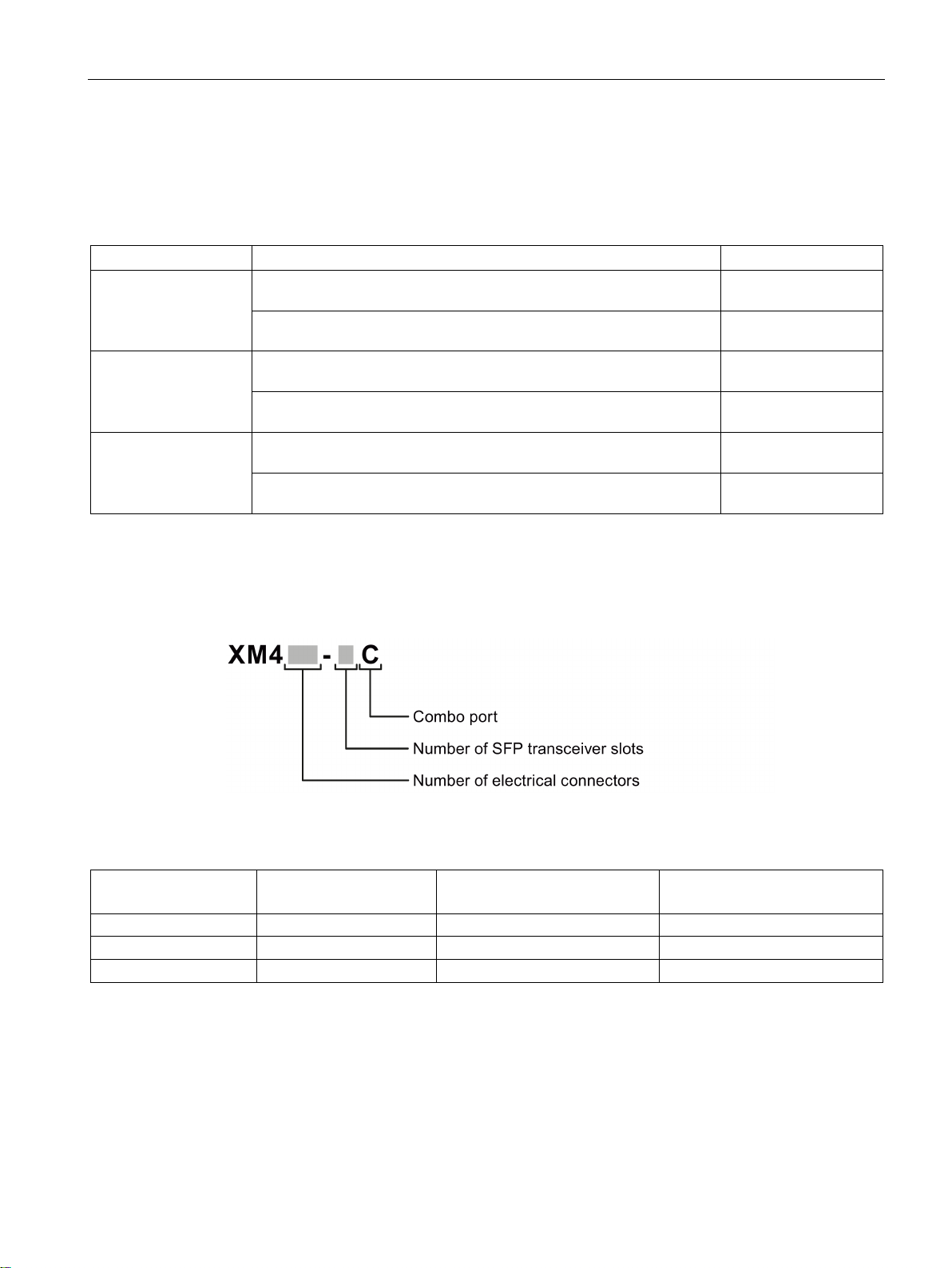
Type designation
Interfaces
Device
Number of electrical connectors
Number of combo ports
Number of slots for pluggable
transceivers
SCALANCE XM408-4C
8 4 4
SCALANCE XM416-4C
16 4 4
4.2 Product overview
SCALANCE XM408-4C 8 RJ-45 ports, 4 pluggable transceiver slots, up to 2 port extenders and
8 RJ-45 ports, 4 pluggable transceiver slots, up to 2 port extenders and
1 function extender, layer 3 integrated
SCALANCE XM408-8C 8 RJ-45 ports, 8 pluggable transceiver slots, up to 2 port extenders and
8 RJ-45 ports, 8 pluggable transceiver slots, up to 2 port extenders and
SCALANCE XM416-4C 16 RJ-45 ports, 4 pluggable transceiver slots, max. 1 port extender and
16 RJ-45 ports, 4 pluggable transceiver slots, max. 1 port extender and
The type designation of a SCALANCE XM-400 is made up of several parts that have the
following meaning:
6GK5 408-4GP00-
6GK5 408-4GQ002AM2
6GK5 408-8GS00-
6GK5 408-8GR00-
6GK5 416-4GS00-
6GK5 416-4GR00-
SCALANCE XM408-8C 8 8 8
SCALANCE XM-400
Operating Instructions, 09/2018, C79000-G8976-C306-08
21

Description of the device
Unpacking and checking
WARNING
Do not use any parts that show evidence of damage
Components of the product
4.2 Product overview
If you use damaged parts, there is no guarantee that the device will function according to
the specification.
If you use damaged parts, this can lead to the following problems:
• Injury to persons
• Loss of the approvals
• Violation of the EMC regulations
• Damage to the device and other components
Use only undamaged parts.
1. Make sure that the package is complete.
2. Check all the parts for transport damage.
The following components are supplied with a SCALANCE XM-400:
● One IE switch with exchangeable storage medium C-PLUG
● One product DVD with documentation and software
● Securing screw for mounting on an S7 standard rail
● A 4-pin terminal block for the power supply (spring-loaded terminal)
● A 2-pin terminal block for the signaling contact (spring-loaded terminal)
● A connecting cable for the serial interface with RJ-11 plug and 9-pin D-sub female
connector
● Covers for the pluggable transceiver slots
– SCALANCE XM408-8C: 8 covers
– SCALANCE XM416-4C: 4 covers
SCALANCE XM-400
22 Operating Instructions, 09/2018, C79000-G8976-C306-08

Description of the device
4.3
Accessories
KEY-PLUG
Type
Article number
KEY-PLUG XM400 Layer 3
6GK5 904-0PA00
C-PLUG
Component
Description
Article number
figuration data, 256 MB
SFP transceiver
Type
Properties
Article number
(multimode), up to max. 3 km
cable (multimode), up to max. 3 km, coated
(single mode) up to max. 26 km
(single mode) up to max. 26 km, varnished
(single mode) up to max. 70 km
(single mode) up to max. 200 km
cable (multimode), up to max. 750 m
cable (single mode) up to max. 10 km
cable (single mode) up to max. 10 km, varnished
cable (single mode) up to max. 40 km
4.3 Accessories
The following accessories are available for SCALANCE XM-400:
C-PLUG Configuration plug, exchangeable storage medium for con-
figuration data, 32 MB
Configuration plug, exchangeable storage medium for con-
SFP991-1 * 1 x 100 Mbps, LC port optical for glass FO cable
SFP991-1 (C) * 1 x 100 Mbps, LC port optical, for glass FO
SFP991-1LD * 1 x 100 Mbps LC port optical for glass FO cable
SFP991-1LD (C) * 1 x 100 Mbps LC port optical for glass FO cable
SFP991-1LH+ * 1 x 100 Mbps LC port optical for glass FO cable
SFP991-1ELH200 * 1 x 100 Mbps LC port optical for glass FO cable
SFP992-1 1 x 1000 Mbps, LC port optical for glass FO
6GK1 900-0AB00
6GK1 900-0AB10
6GK5 991-1AD00-8AA0
6GK5 991-1AD00-8FA0
6GK5 991-1AF00-8AA0
6GK5 991-1AF00-8FA0
6GK5 991-1AE00-8AA0
6GK5 991-1AE30-8AA0
6GK5 992-1AL00-8AA0
SFP992-1+ 1 x 1000 Mbps, LC port optical for glass FO
SFP992-1LD 1 x 1000 Mbps LC port optical for glass FO
SFP992-1LD (C) 1 x 1000 Mbps LC port optical for glass FO
SFP992-1LH 1 x 1000 Mbps LC port optical for glass FO
SCALANCE XM-400
Operating Instructions, 09/2018, C79000-G8976-C306-08
6GK5 992-1AG00-8AA0
cable (multimode), up to max. 2 km
6GK5 992-1AM00-8AA0
6GK5 992-1AM00-8FA0
6GK5 992-1AN00-8AA0
23

Description of the device
Type
Properties
Article number
cable (single mode) up to max. 70 km
* Cannot be operated in SFP+ slots.
Pluggable transceivers with the supplement (C) in the type name have varnished printed circuit boards
(conformal coating).
Note
Restriction for pluggable transceivers
The maximum ambient temperature changes if you use pluggable transceivers:
•
•
For the values of the ambient temperature without pluggable transceiver
section "
Bidirectional plug-in transceiver SFP
Type
Properties
Article number
nm, receives at 1310 nm
nm, receives at 1550 nm
Port extender
Type
Properties
Article number
PE408PoE
8 x 10/100/1000 Mbps, RJ-45 ports with PoE
6GK5 408-0PA00-8AP2
PE400-8SFP
8 x 100/1000 Mbps, SFP ports
6GK5 400-8AS00-8AP2
4.3 Accessories
SFP992-1LH+ 1 x 1000 Mbps LC port optical for glass FO
SFP992-1ELH 1 x 1000 Mbps LC port optical for glass FO
cable (single mode) up to max. 120 km
6GK5 992-1AP00-8AA0
6GK5 992-1AQ00-8AA0
If you use transceivers of the types multimode and LD, the maximum ambient
temperature is reduced to 60 °C.
If you use transceivers of the types LH, LH+, ELH or ELH200, the maximum ambient
temperature is reduced to 50 °C.
You can only use up to 4 pluggable transceivers of the types LH, LH+, ELH or ELH200 in
the basic device.
s, refer to the
Technical specifications (Page 67)".
Bidirectional plug-in transceivers feature only one fiber connection. They transmit and
receive on two different wavelengths. To establish a connection, you need two matching
bidirectional SFPs. The connected SFPs must respectively transmit on the wavelength at
which the connection partner receives.
SFP992-1BXMT 1 x 1000 Mbps LC port optical for glass FO
(multimode) with max. 500 m, transmits at 1550
SFP992-1BXMR 1 x 1000 Mbps LC port optical for glass FO
(multimode) with max. 500 m, transmits at 1310
PE408 8 x 10/100/1000 Mbps RJ-45 ports 6GK5 408-0GA00-8AP2
6GK5 992-1AL00-8TA0
6GK5 992-1AL00-8RA0
SCALANCE XM-400
24 Operating Instructions, 09/2018, C79000-G8976-C306-08

Description of the device
Function Extender BUS ANALYZER Agent XM-400
Device
Properties
Article number
function extender
PoE power supply
Type
Input voltage
Output voltage
Output current
Article number
SCALANCE PS924 PoE
24 VDC
54 VDC
1.6 A
6GK5 924-0PS00-1AA2
SCP / STP transceiver
Type
Properties
Article number
(multimode) up to max. 750 m
(single mode) up to max. 10 km
(multimode) up to max. 3 km
(single mode) up to max. 26 km
4.3 Accessories
BUS ANALYZER
Agent XM-400 as
SCALANCE PS9230
PoE
SCP992-1 1 x 1000 Mbps SC port optical for glass FO cable
SCP992-1LD 1 x 1000 Mbps SC port optical for glass FO cable
STP991-1 1 x 100 Mbps ST port optical for glass FO cable
STP991-1LD 1 x 100 Mbps ST port optical for glass FO cable
100/240 VAC
50/60 Hz
4 x internal monitor ports for port mirroring 9AE 4140-2AA00
54 VDC 1.6 A 6GK5 923-0PS00-3AA2
6GK5 992-1AJ00-8AA0
6GK5 992-1AK00-8AA0
6GK5 991-1AB00-8AA0
6GK5 991-1AC00-8AA0
Can only be operated in SCP and STP slots.
SCALANCE XM-400
Operating Instructions, 09/2018, C79000-G8976-C306-08
25

Description of the device
4.4
Spare parts
Component
Description
Article number
exchangeable storage medium for configuration data
pack of 5
pack of 5
pack of 5
pack of 5
pack of 1
4.4 Spare parts
The following spare parts are available for SCALANCE XM-400:
C-PLUG Configuration plug,
Spring-loaded terminal block, 4
terminals
Spring-loaded terminal block, 2
terminals
Screw terminal block, 4 terminals 4-terminal screw terminal block to connect the power supply
Screw terminal block, 2 terminals 2-terminal screw terminal block to connect the power supply
Securing screw Screw for mounting on an S7-1500 and S7-300 standard
4-terminal spring-loaded terminal block to connect the power supply (24 VDC),
for SCALANCE X/W/S/M,
pack of 5
2-terminal spring-loaded terminal block to connect the sig-
naling contact (24 VDC),
for SCALANCE X/W/S/M,
(24 VDC),
for SCALANCE X/W/S/M,
(24 VDC),
for SCALANCE X/W/S/M,
rail,
for SCALANCE X/W,
6GK1 900-0AB00
6GK5 980-1DB10-0AA5
6GK5 980-0BB10-0AA5
6GK5 980-1DB00-0AA5
6GK5 980-0BB00-0AA5
6GK5 980-4AA00-0AA5
Connecting cable (RJ-11/RS-
232)
Preassembled, serial cable with RJ-11 and RS-232 plug,
Length: 3 m
6GK5 980-3BB00-0AA5
SCALANCE XM-400
26 Operating Instructions, 09/2018, C79000-G8976-C306-08
Description of the device
4.5
Device views
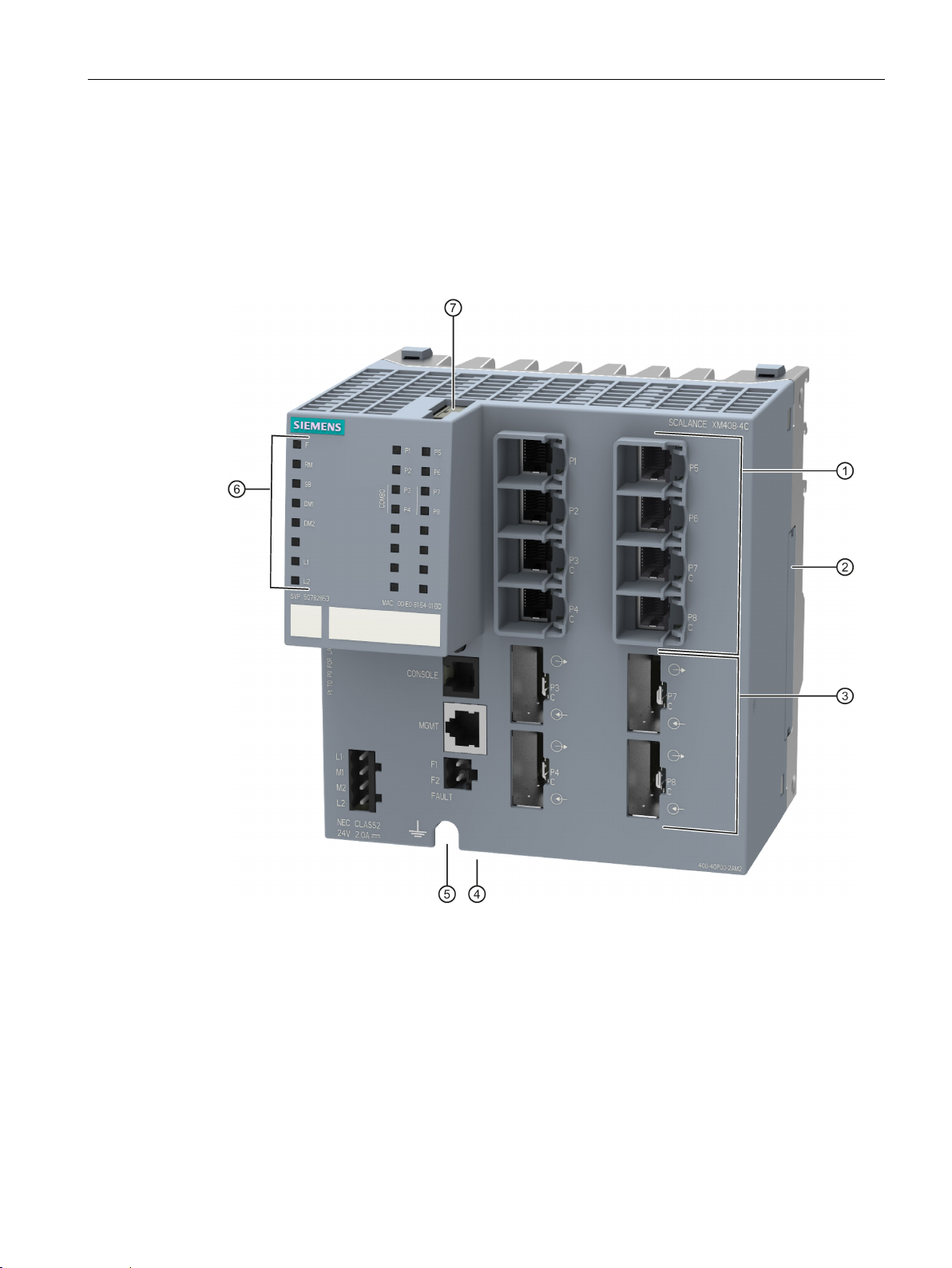
4.5.1
SCALANCE XM408-4C
①
Electrical ports
②
Expansion interface with cover
③
Slots for pluggable transceivers (STP and DCP)
④
Location for securing to an S7 standard rail (on the underside of the device, not in figure)
⑤
Grounding (on rear of device, not shown in figure)
⑥
LED display
⑦
Slot for C-PLUG / KEY-PLUG
4.5 Device views
The following figure shows an overview of the components of the SCALANCE XM408-4C.
SCALANCE XM-400
Operating Instructions, 09/2018, C79000-G8976-C306-08
27
 Loading...