

Siemens SIMATIC NET SCALANCE X-300EEC Compact Operating Instructions

SIMATIC NET
Industrial Ethernet switches
SCALANCE X-300EEC
Introduction
1
Compact Operating Instructions
Safety notes
Recommendations on
network security
Description of the device
Assembling
Connecting
Technical data
Dimension drawings
2
3
4
5
6
7
8
Approvals
9
11/2019
A5E02630809-14
Legal information
Warning notice system
This manual contains notices you have to observe in order to ensure your personal safety, as well as to prevent
damage to property. The notices referring to your personal safety are highlighted in the manual by a safety alert
symbol, notices referring only to property damage have no safety alert symbol. These notices shown below are
graded according to the degree of danger.
DANGER
indicates that death or severe personal injury will result if proper precautions are not taken.
WARNING
indicates that death or severe personal injury may result if proper precautions are not taken.
CAUTION
indicates that minor personal injury can result if proper precautions are not taken.
NOTICE
indicates that property damage can result if proper precautions are not taken.
If more than one degree of danger is present, the warning notice representing the highest degree of danger will be
used. A notice warning of injury to persons with a safety alert symbol may also include a warning relating to property
damage.
Qualified Personnel
The product/system described in this documentation may be operated only by personnel qualified for the specific
task in accordance with the relevant documentation, in particular its warning notices and safety instructions. Qualified
personnel are those who, based on their training and experience, are capable of identifying risks and avoiding
potential hazards when working with these products/systems.
Proper use of Siemens products
Note the following:
WARNING
Siemens products may only be used for the applications described in the catalog and in the relevant technical
documentation. If products and components from other manufacturers are used, these must be recommended or
approved by Siemens. Proper transport, storage, installation, assembly, commissioning, operation and
maintenance are required to ensure that the products operate safely and without any problems. The permissible
ambient conditions must be complied with. The information in the relevant documentation must be observed.
Trademarks
All names identified by ® are registered trademarks of Siemens AG. The remaining trademarks in this publication
may be trademarks whose use by third parties for their own purposes could violate the rights of the owner.
Disclaimer of Liability
We have reviewed the contents of this publication to ensure consistency with the hardware and software described.
Since variance cannot be precluded entirely, we cannot guarantee full consistency. However, the information in this
publication is reviewed regularly and any necessary corrections are included in subsequent editions.
Siemens AG
Digital Industries
Postfach 48 48
90026 NÜRNBERG
GERMANY
A5E02630809-14
Ⓟ 11/2019 Subject to change
Copyright © Siemens AG 2009 - 2019.
All rights reserved

Table of contents
1 Introduction...................................................................................................................................................5
2 Safety notes................................................................................................................................................11
3 Recommendations on network security......................................................................................................13
4 Description of the device ............................................................................................................................17
4.1 Product overview....................................................................................................................17
4.2 Product properties and device views .....................................................................................20
4.3 LED display ............................................................................................................................25
4.4 SET/SELECT button ..............................................................................................................28
4.5 C-PLUG..................................................................................................................................30
4.5.1 Area of application and function of the C-PLUG ....................................................................30
4.5.2 Removing and inserting the C-PLUG (compact housing) ......................................................30
5 Assembling .................................................................................................................................................33
5.1 Safety notices for installation .................................................................................................33
5.2 Installation ..............................................................................................................................35
5.3 Overview of the methods of installation .................................................................................36
5.4 Installation on a DIN rail .........................................................................................................36
5.5 Installation on a standard rail .................................................................................................37
5.6 Wall mounting ........................................................................................................................38
5.7 19" rack mounting ..................................................................................................................39
6 Connecting .................................................................................................................................................41
6.1 Safety when connecting up ....................................................................................................41
6.2 Notes on commissioning ........................................................................................................42
6.3 Wiring rules ............................................................................................................................42
6.4 Connecting the switch ............................................................................................................43
6.5 Connecting the grounding ......................................................................................................43
6.6 Signaling contact....................................................................................................................45
6.6.1 Signaling contact 24 to 48 V ..................................................................................................45
6.6.2 Signaling contact 100 to 240 VAC / 60 to 250 VDC...............................................................46
6.7 Power supply..........................................................................................................................48
6.7.1 Power supply for the X-300EEC / XR-300M EEC .................................................................48
6.7.2 Connecting devices with 24 VDC power supply.....................................................................49
6.7.2.1 Overview ................................................................................................................................50
6.7.2.2 Connecting the external 24 VDC power supply .....................................................................51
6.7.2.3 Redundant power supply .......................................................................................................52
SCALANCE X-300EEC
Compact Operating Instructions, 11/2019, A5E02630809-14 3

Table of contents
6.7.2.4 Connecting a redundant power supply to the X-300EEC.......................................................52
6.7.3 Connecting devices with 100 to 240 VAC power supply........................................................54
6.7.3.1 Overview ................................................................................................................................55
6.7.3.2 Connecting the 100 to 240 VAC power supply ......................................................................55
7 Technical data ............................................................................................................................................57
7.1 Construction, installation and environmental conditions ........................................................57
7.2 Connectors and electrical data...............................................................................................60
7.3 Cable lengths .........................................................................................................................62
7.4 Other properties .....................................................................................................................63
8 Dimension drawings ...................................................................................................................................65
9 Approvals....................................................................................................................................................73
9.1 Restriction: as of hardware version 3.....................................................................................80
9.2 Mechanical stability ................................................................................................................82
Index...........................................................................................................................................................83
SCALANCE X-300EEC
4 Compact Operating Instructions, 11/2019, A5E02630809-14

Introduction
Purpose of the compact operating instructions
These compact operating instructions support you when installing and connecting devices of
the SCALANCE X‑300EEC product group.
Validity of these compact operating instructions
These compact operating instructions are valid for the following devices:
● SCALANCE X302-7EEC
● SCALANCE X307-2EEC
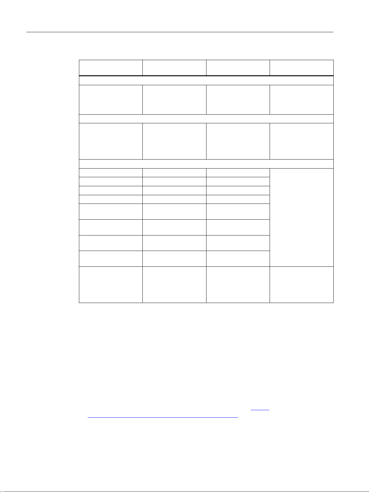
Designations used
Classification Description Designation / example
Product line For all devices and variants of all product groups within the SCALANCE
X-300 product line, the term "IE Switch X-300" is used.
Product group For all devices and variants of a product group, only the product group is
used.
Device For a device, only the device name is used. X302‑7EEC
Variant For a variant of the device, the device name has the appropriate variant
added to it in brackets.
IE Switches X-300
X-300EEC
X302-7EEC
(2 electrical ports,
7 optical ports)
1
Overview of technical documentation on the IE switches SCALANCE X‑300
You will find the technical documentation for the SCALANCE X‑300 product line in the following
documents:
● Configuration manual (PH), available as PDF document
The configuration manual describes the software for the two product lines SCALANCE
X‑300 and SCALANCE X‑400.
● Compact operating instructions (BAK), supplied with the device in printed form
The compact operating instructions describe devices within a product group.
● Operating instructions (BA), available as PDF document
The operating instructions describe all devices of the product line and provide generally
valid information on the devices.
SCALANCE X-300EEC
Compact Operating Instructions, 11/2019, A5E02630809-14 5
Introduction
Type of document Relevant for the follow‐
ing products
Configuration Manual
PH X300/X400 All devices of the SCA‐
LANCE X‑300 and SCA‐
LANCE X‑400 product
lines
Operating instructions
BA X-300 All devices of the SCA‐
LANCE X‑300 product
line
Compact operating instructions
BAK X-300 SCALANCE X-300 A5E00982643A Device description,
BAK X-300M SCALANCE X-300M A5E02630801A
BAK XR-300M SCALANCE XR-300M A5E02661171A
BAK X-300 EEC SCALANCE X-300EEC A5E02661176A
BAK XR-300M EEC SCALANCE XR-300M
EEC
BAK X-300M PoE SCALANCE X-300M
PoE
BAK XR-300M PoE SCALANCE XR-300M
PoE
BAK MM900 SCALANCE MM900
(media modules)
BAK SFP
Information sheet
SCALANCE SFP (plug-
in transceivers)
Document identification
number
C79000-G89000-C187 Configuration of the de‐
A5E01113043 Device description,
A5E02630809A
A5E02630810A
A5E02661178A
A5E02630805A
A5E02630804A
A5E02648904A
Contents
vice
technical specifications,
information on instal‐
ling, connecting and
commissioning
technical specifications,
information on instal‐
ling, connecting and
commissioning
Device description,
technical specifications,
information on instal‐
ling, connecting and
commissioning
Documentation on configuration
You will find detailed information on configuring the devices in the configuration manual:
● SIMATIC NET: Industrial Ethernet switches SCALANCE X-300 / X-400 Configuration
Manual
You will find the Configuration Manual here:
● On the data medium that ships with some products:
– Product CD / product DVD
– SIMATIC NET Manual Collection
● On the Internet pages of Siemens Industry Online Support (https://
support.industry.siemens.com/cs/ww/en/ps/15297/man).
SCALANCE X-300EEC
6 Compact Operating Instructions, 11/2019, A5E02630809-14

Additional documentation
The manual
Introduction
● "SIMATIC NET Industrial Ethernet Twisted Pair and Fiber Optic Networks (
support.industry.siemens.com/cs/ww/en/view/1172207)"
contains additional information on other SIMATIC NET products that you can operate along
with the devices of the SCALANCE X‑300 product line in an Industrial Ethernet network.
Integration in STEP 7 projects
The current GSDML file must be used for integration in STEP 7 V5.4 SP5 projects. This applies
to all products covered by these operating instructions.
You can obtain the relevant GSD file from the Internet under the following entry ID:
46183514 (https://support.industry.siemens.com/cs/ww/en/view/46183514)
You will find the file for the firmware update V3.3.1 for X-300 under entry ID "46183538".
Further documentation
In the system manuals "Industrial Ethernet / PROFINET Industrial Ethernet" and "Industrial
Ethernet / PROFINET passive network components", you will find information on other
SIMATIC NET products that you can operate along with the devices of this product line in an
Industrial Ethernet network.
There, you will find among other things optical performance data of the communications partner
that you require for the installation.
https://
You will find the system manuals here:
● On the data medium that ships with some products:
– Product CD / product DVD
– SIMATIC NET Manual Collection
● On the Internet pages of Siemens Industry Online Support:
– Industrial Ethernet / PROFINET Industrial Ethernet System Manual (https://
– Industrial Ethernet / PROFINET Passive Network Components System Manual (https://
SIMATIC NET manuals
You will find the SIMATIC NET manuals here:
● On the data medium that ships with some products:
– Product CD / product DVD
– SIMATIC NET Manual Collection
● On the Internet pages of Siemens Industry Online Support (https://
support.industry.siemens.com/cs/ww/en/ps/15247).
support.industry.siemens.com/cs/ww/en/view/27069465)
support.industry.siemens.com/cs/ww/en/view/84922825)
SCALANCE X-300EEC
Compact Operating Instructions, 11/2019, A5E02630809-14 7

Introduction
SIMATIC NET glossary
Explanations of many of the specialist terms used in this documentation can be found in the
SIMATIC NET glossary.
You will find the SIMATIC NET glossary here:
● SIMATIC NET Manual Collection or product DVD
The DVD ships with certain SIMATIC NET products.
● On the Internet under the following address:
50305045 (
Security information
Siemens provides products and solutions with industrial security functions that support the
secure operation of plants, systems, machines and networks.
In order to protect plants, systems, machines and networks against cyber threats, it is
necessary to implement – and continuously maintain – a holistic, state-of-the-art industrial
security concept. Siemens’ products and solutions constitute one element of such a concept.
Customers are responsible for preventing unauthorized access to their plants, systems,
machines and networks. Such systems, machines and components should only be connected
to an enterprise network or the internet if and to the extent such a connection is necessary and
only when appropriate security measures (e.g. firewalls and/or network segmentation) are in
place.
https://support.industry.siemens.com/cs/ww/en/view/50305045)
Catalogs
For additional information on industrial security measures that may be implemented, please
visit
https://www.siemens.com/industrialsecurity (https://www.siemens.com/industrialsecurity)
Siemens’ products and solutions undergo continuous development to make them more secure.
Siemens strongly recommends that product updates are applied as soon as they are available
and that the latest product versions are used. Use of product versions that are no longer
supported, and failure to apply the latest updates may increase customers’ exposure to cyber
threats.
To stay informed about product updates, subscribe to the Siemens Industrial Security RSS
Feed under
https://www.siemens.com/industrialsecurity (https://www.siemens.com/industrialsecurity)
You will find the article numbers for the Siemens products of relevance here in the following
catalogs:
● SIMATIC NET Industrial Communication / Industrial Identification, catalog IK PI
● SIMATIC Products for Totally Integrated Automation and Micro Automation, catalog ST 70
● Industry Mall - catalog and ordering system for automation and drive technology, Online
catalog (https://mall.industry.siemens.com/goos/WelcomePage.aspx?regionUrl=/
de&language=en)
You can request the catalogs and additional information from your Siemens representative.
SCALANCE X-300EEC
8 Compact Operating Instructions, 11/2019, A5E02630809-14

Device defective
If a fault develops, please send the device to your SIEMENS service center for repair. Repairs
on-site are not possible.
Recycling and disposal
The products are low in pollutants, can be recycled and meet the requirements of the WEEE
directive 2012/19/EU for the disposal of electrical and electronic equipment.
Do not dispose of the products at public disposal sites.
For environmentally friendly recycling and the disposal of your old device contact a certified
disposal company for electronic scrap or your Siemens contact (Product return (
support.industry.siemens.com/cs/ww/en/view/109479891)).
Note the different national regulations.
SIMATIC NET, SCALANCE, C-PLUG, OLM
Trademarks
Introduction
https://
The following and possibly other names not identified by the registered trademark sign ® are
registered trademarks of Siemens AG:
SCALANCE X-300EEC
Compact Operating Instructions, 11/2019, A5E02630809-14 9

Introduction
SCALANCE X-300EEC
10 Compact Operating Instructions, 11/2019, A5E02630809-14
Safety notes
Read the safety notices
Note the following safety notices. These relate to the entire working life of the device.
You should also read the safety notices relating to handling in the individual sections,
particularly in the sections "Installation" and "Connecting up".
CAUTION
To prevent injury, read the manual before use.
Safety notices on use in hazardous areas
General safety notices relating to protection against explosion
WARNING
EXPLOSION HAZARD
2
Do not open the device when the supply voltage is turned on.
Safety notices when using the device according to Hazardous Locations (HazLoc)
If you use the device under HazLoc conditions you must also keep to the following safety
notices in addition to the general safety notices for protection against explosion:
This equipment is suitable for use in Class I, Division 2, Groups A, B, C and D or non-hazardous
locations only.
This equipment is suitable for use in Class I, Zone 2, Group IIC or non-hazardous locations only.
SCALANCE X-300EEC
Compact Operating Instructions, 11/2019, A5E02630809-14 11

Safety notes
SCALANCE X-300EEC
12 Compact Operating Instructions, 11/2019, A5E02630809-14

Recommendations on network security
NOTICE
Information security
Connect to the device and change the standard passwords for the users "admin" and "user"
before you operate the device. To be able to change passwords you need to be logged in with
write access to the configuration data.
To prevent unauthorized access, note the following security recommendations.
General
● You should make regular checks to make sure that the device meets these
recommendations and/or other security guidelines.
● Evaluate your plant as a whole in terms of security. Use a cell protection concept with
suitable products (https://www.industry.siemens.com/topics/global/en/industrial-security/
pages/default.aspx).
● When the internal and external network are disconnected, an attacker cannot access
internal data from the outside. Therefore operate the device only within a protected network
area.
3
● For communication via non-secure networks use additional devices with VPN functionality
to encrypt and authenticate the communication.
● Terminate management connections correctly (WBM. Telnet, SSH etc.).
Physical access
● Restrict physical access to the device to qualified personnel because the plug-in data
medium can contain sensitive data.
● Lock unused physical interfaces on the device. Unused interfaces can be used to gain
access to the plant without permission.
Software (security functions)
● Keep the firmware up to date. Check regularly for security updates for the device. You can
find information on this at the Industrial Security (https://www.siemens.com/
industrialsecurity) website.
● Inform yourself regularly about security recommendations published by Siemens
ProductCERT (https://www.siemens.com/cert/en/cert-security-advisories.htm).
● Only activate protocols that you require to use the device.
● Restrict access to the management of the device with rules in an access control list (ACL).
SCALANCE X-300EEC
Compact Operating Instructions, 11/2019, A5E02630809-14 13

Recommendations on network security
● The option of VLAN structuring provides protection against DoS attacks and unauthorized
access. Check whether this is practical or useful in your environment.
● Use a central logging server to log changes and accesses. Operate your logging server
within the protected network area and check the logging information regularly.
Passwords
● Define rules for the assignment of passwords.
● Regularly change your passwords to increase security.
● Use passwords with a high password strength.
● Make sure that all passwords are protected and inaccessible to unauthorized persons.
● Do not use the same password for different users and systems.
Certificates and keys
● On the device there is a preset SSL certificate with key. Replace this certificate with a selfmade certificate with key. We recommend that you use a certificate signed either by a
reliable external or by an internal certification authority.
● Use a certification authority including key revocation and management to sign certificates.
● Make sure that user-defined private keys are protected and inaccessible to unauthorized
persons.
● It is recommended that you use password-protected certificates in the PKCS #12 format
● Verify certificates and fingerprints on the server and client to prevent "man in the middle"
attacks.
● It is recommended that you use certificates with a key length of at least 2048 bits.
● Change certificates and keys immediately, if there is a suspicion of compromise.
SCALANCE X-300EEC
14 Compact Operating Instructions, 11/2019, A5E02630809-14

Secure/non-secure protocols
● Avoid or disable non-secure protocols, for example Telnet and TFTP. For historical reasons,
these protocols are available, however not intended for secure applications. Use nonsecure protocols on the device with caution.
● Check whether use of the following protocols and services is necessary:
– Non authenticated and unencrypted ports
– MRP, HRP
– LLDP
– DHCP Options 66/67
The following protocols provide secure alternatives:
– HTTP → HTTPS
– TFTP → FTPS
– Telnet → SSH
– SNTP → NTP
– SNMPv1/v2c → SNMPv3
Check whether use of SNMPv1/v2c. is necessary. SNMPv1/v2c are classified as nonsecure. Use the option of preventing write access. The device provides you with suitable
setting options.
If SNMP is enabled, change the community names. If no unrestricted access is
necessary, restrict access with SNMP.
Use the authentication and encryption mechanisms of SNMPv3.
Recommendations on network security
Available protocols
● Use secure protocols when access to the device is not prevented by physical protection
measures.
● If you require non-secure protocols and services, operate the device only within a protected
network area.
● Restrict the services and protocols available to the outside to a minimum.
● For the DCP function, enable the "DCP read-only" mode after commissioning.
The following list provides you with an overview of the open protocol ports.
The table includes the following columns:
● Protocol
● Port number
● Port status
– Open
– Closed
● Factory setting
Indicates the state of the port on delivery or after reset to factory settings.
SCALANCE X-300EEC
Compact Operating Instructions, 11/2019, A5E02630809-14 15

Recommendations on network security
● Authentication
Specifies whether the communication partner is authenticated.
● Encryption
Specifies whether or not the transfer is encrypted.
Protocol Port number Port status Factory setting Authentication Encryption
FTP TCP/21 Open Open Yes No
SSH TCP/22 Open Open Yes Yes
TELNET TCP/23 Open
HTTP TCP/80 Open
PROFINET IO
Service
HTTPS TCP/443 Open Open Yes Yes
DHCP UDP/68 Open
SNTP UDP/123 Open
NTP (secure) Yes
SNMP UDP/161 Open
RADIUS UDP/1812,
PROFINET IO UDP/34964
TCP/84 Open Open No No
1813
UDP/49152,
49153 *
Open Yes Yes
(when config‐
ured)
Open Yes No
(when config‐
ured)
Open No No
(when config‐
ured)
Closed No No
(when config‐
ured)
Open Yes Yes
(when config‐
ured)
Open Open Yes No
Open
(when config‐
)
ured)
Open No No
(SNMPv3)
*) These ports are assigned dynamically and can differ from the values specified here.
SCALANCE X-300EEC
16 Compact Operating Instructions, 11/2019, A5E02630809-14

Description of the device
4.1 Product overview
Article numbers
Device / Ports Properties Article number
X302-7EEC
● 2 electrical ports
● 7 optical ports
X307-2EEC
● 7 electrical ports
● 2 optical ports
1 x power supply unit 24 to 48 V DC 6GK5302-7GD00-1EA3
1 x power supply unit 24 to 48 V DC
PCB coated
2 x power supply unit 24 to 48 V DC 6GK5302-7GD00-2EA3
2 x power supply unit 24 to 48 V DC
PCB coated
1 x power supply unit 100 to 240 V AC / 60 to 250 V DC 6GK5302-7GD00-3EA3
1 x power supply unit 100 to 240 V AC / 60 to 250 V DC
PCB coated
2 x power supply unit 100 to 240 V AC / 60 to 250 V DC 6GK5302-7GD00-4EA3
2 x power supply unit 100 to 240 V AC / 60 to 250 V DC
PCB coated
1 x power supply unit 24 to 48 V DC 6GK5307-2FD00-1EA3
1 x power supply unit 24 to 48 V DC
PCB coated
2 x power supply unit 24 to 48 V DC 6GK5307-2FD00-2EA3
2 x power supply unit 24 to 48 V DC
PCB coated
1 x power supply unit 100 to 240 V AC / 60 to 250 V DC 6GK5307-2FD00-3EA3
1 x power supply unit 100 to 240 V AC / 60 to 250 V DC
PCB coated
2 x power supply unit 100 to 240 V AC / 60 to 250 V DC 6GK5307-2FD00-4EA3
2 x power supply unit 100 to 240 V AC / 60 to 250 V DC
PCB coated
6GK5302-7GD00-1GA3
6GK5302-7GD00-2GA3
6GK5302-7GD00-3GA3
6GK5302-7GD00-4GA3
6GK5307-2FD00-1GA3
6GK5307-2FD00-2GA3
6GK5307-2FD00-3GA3
6GK5307-2FD00-4GA3
4
* See naming key below
SCALANCE X-300EEC
Compact Operating Instructions, 11/2019, A5E02630809-14 17
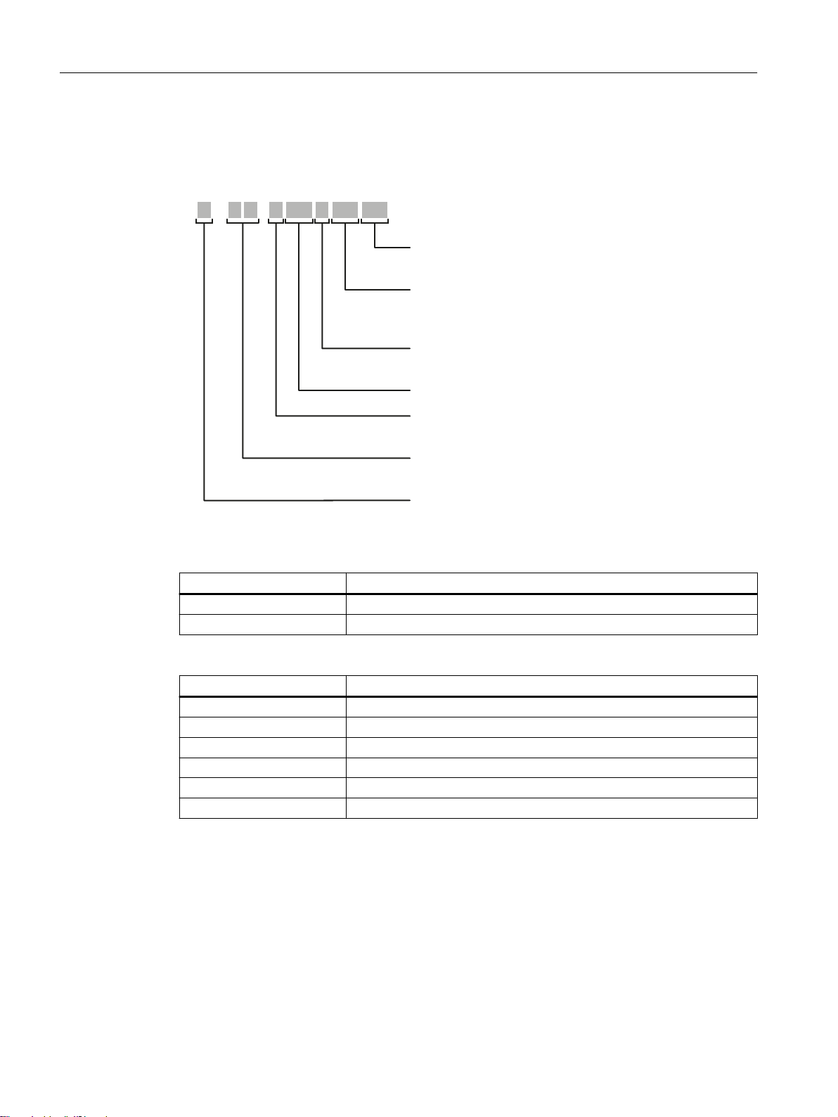
>@&RPSDFWKRXVLQJ
R5DFNGHYLFH
1XPEHURIHOHFWULFDOSRUWVRU
WRWDOQXPEHURISRUWVLQPRGXODUGHYLFHV
1XPEHURIRSWLFDOSRUWVRU
QXPEHURIPRGXOHVORWVLQPRGXODUGHYLFHV
>@6WDQGDUGYHUVLRQ
TS7UDQVSRUWDWLRQ6\VWHP
>@6WDQGDUGYHUVLRQ
EEC([SDQGHGWHPSHUDWXUHUDQJH
PoE3RZHURYHU(WKHUQHW
>@'HYLFHVZLWKRXWPRGXOHVORWV
M0RGXODUGHYLFH
,QWHUIDFH
X 3 -
Description of the device
4.1 Product overview
Structure of the type designation
The type designation of an IE Switch X-300 is made up of several parts that have the following
meaning:
Interfaces of devices without optical ports:
Interface Property
FE Electrical RJ-45 port for 10/100 Mbps.
[-] Electrical RJ-45 port for 10/100 Mbps or 10/100/1000 Mbps.
Interfaces of devices with optical ports:
Interface Property
FE SC port 100 Mbps multimode FO cable (up to max. 5 km).
LD FE SC port 100 Mbps single mode FO cable (up to max. 26 km).
[-] SC port 1000 Mbps multimode FO cable (up to max. 750 m).
LD SC port 1000 Mbps single mode FO cable (up to max. 10 km).
LH SC port 1000 Mbps single mode FO cable (up to max. 40 km).
LH+ SC port 1000 Mbps single mode FO cable (up to max. 70 km).
If information applies to all devices, the term "IE Switches X-300" is used. If information applies
to only a particular product group, the relevant names will be used without extra information on
18 Compact Operating Instructions, 11/2019, A5E02630809-14
SCALANCE X-300EEC
the type or number of interfaces. Examples: "X-300" stands for non-modular devices with a
compact housing, "XR-300" means all rack devices, "X-300M" means all modular devices etc.
Note
SCALANCE X320-3LD FE
The SCALANCE X320-3LD FE deviates from the type designation in that it has an SC port for
multimode fiber-optic cable up to a maximum of 5 km in length and two SC ports for single mode
fiber-optic cable up to a maximum of 26 km in length.
● Port 21: Multimode
● Port 22: LD (long distance, single mode)
● Port 23: LD (long distance, single mode)
Unpacking and checking
WARNING
Do not use any parts that show evidence of damage
Description of the device
4.1 Product overview
Scope of delivery
If you use damaged parts, there is no guarantee that the device will function according to the
specification.
If you use damaged parts, this can lead to the following problems:
● Injury to persons
● Loss of the approvals
● Violation of the EMC regulations
● Damage to the device and other components
Use only undamaged parts.
1. Make sure that the package is complete.
2. Check all the parts for transport damage.
The following components are supplied with a SCALANCE X-300EEC:
● 1 x device with 1 x C-PLUG exchangeable medium
● 1 x product CD with documentation and software
SCALANCE X-300EEC
Compact Operating Instructions, 11/2019, A5E02630809-14 19

Description of the device
4.2 Product properties and device views
Additional parts are listed in the following table according to the device version:
Table 4-1 Overview of the components shipped with the X‑300EEC product group
Device Plug-in terminal block
SCALANCE X302-7EEC
1 x power supply unit 24 V DC 1 x 2-pin 1 x 4-pin ‑
2 x power supply unit 24 V DC 2 x 2-pin 2 x 4-pin ‑
1 x power supply unit 100 to 240 V AC /
60 to 250 V DC
2 x power supply unit 100 to 240 V AC /
60 to 250 V AC
SCALANCE X307-2EEC
1 x power supply unit 24 V DC 1 x 2-pin 1 x 4-pin ‑
2 x power supply unit 24 V DC 2 x 2-pin 2 x 4-pin ‑
1 x power supply unit 100 to 240 V AC /
60 to 250 V DC
2 x power supply unit 100 to 240 V AC /
60 to 250 V AC
Signaling contact
with contact pins
1 x 3-pin ‑ 1 x 3-pin
2 x 3-pin ‑ 2 x 3-pin
1 x 3-pin ‑ 1 x 3-pin
2 x 3-pin ‑ 2 x 3-pin
24 to 48 V DC 100 to 240 V AC /
Power supply
60 to 250 V DC
4.2 Product properties and device views
Variants
The SCALANCE X‑300EEC is a 19"/2 device with 9 ports for the connection of end devices or
other network segments. There are 2 device types with the following ports:
● SCALANCE X302-7EEC
– 2 x RJ-45 jacks
– 7 x FO ports for multimode fiber, LC connector
● SCALANCE X307-2EEC
– 7 x RJ-45 jacks
– 2 x FO ports for multimode fiber, LC connector
SCALANCE X-300EEC
20 Compact Operating Instructions, 11/2019, A5E02630809-14
Device versions
Description of the device
4.2 Product properties and device views
The X‑300EEC is available in the following alternative versions:
● Power supply
– Power supply unit 24 to 48 VDC
– Multirange power supply unit 100 to 240 VAC / 60 to 250 VDC
● Power supply unit
– Single
– Redundant
● Printed board
– Varnished (suitable for aggressive environments)
– Unvarnished
This combination of versions results in the product variants listed in section Product overview
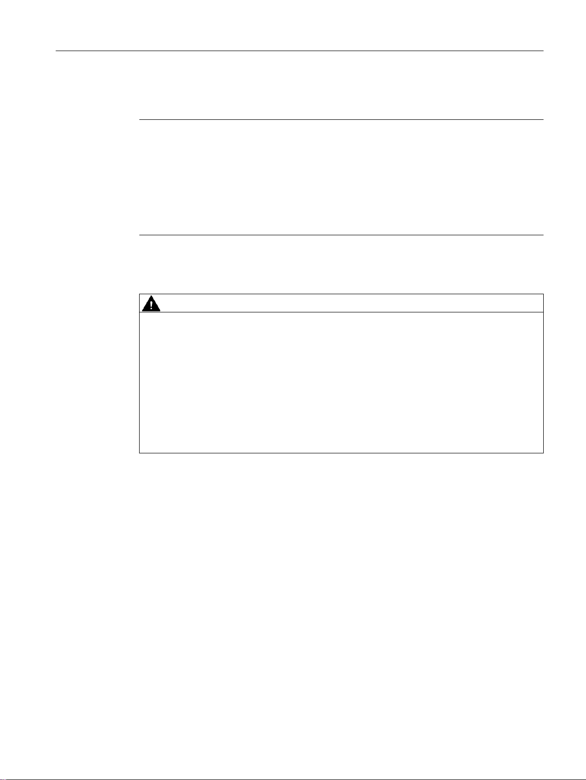
(Page 17).
Figure 4-1 SCALANCE X302‑7EEC (from below) with protective bracket and LC connector
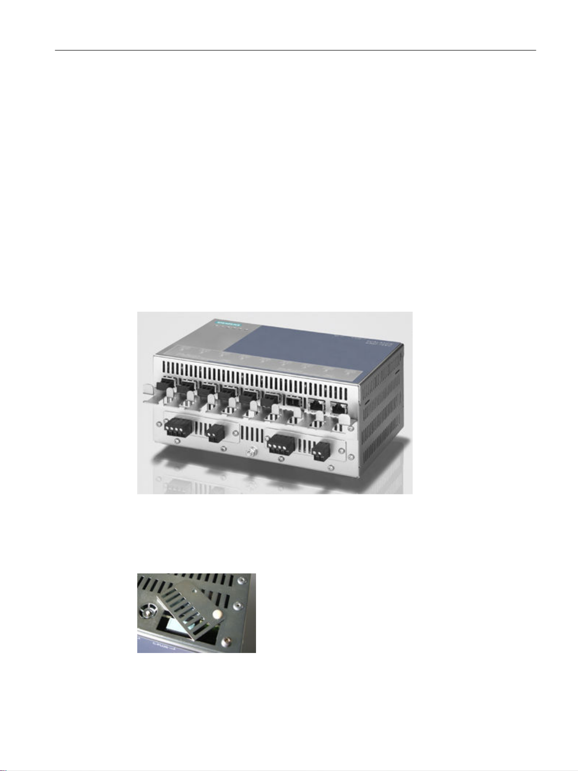
Replacing the C‑PLUG
In the X‑300EEC devices, the slot for the C-PLUG is on the top on the housing.
Figure 4-2 C-PLUG of the X‑300EEC
SCALANCE X-300EEC
Compact Operating Instructions, 11/2019, A5E02630809-14 21

Description of the device
4.2 Product properties and device views
NOTICE
The C-PLUG may only be removed or inserted when the power supply to the device is turned
off.
In a device with a varnished printed circuit board, you may only use a C-PLUG with a
varnished board.
To remove the C-PLUG, open the slider and close it again after inserting the C‑PLUG.
Terminal block for signaling contact and power supply
The terminal block of the X‑300EEC for connecting the signaling contact and power supply has
the following terminals:
● F1, F2: Signaling contact
The 2 signaling contacts on the device version with a redundant power supply are energized
in parallel.
● L1, M1: Power supply 1
RJ-45 interface
● L2, M2: Power supply 2 (redundant version)
The power supply units for the power supply are available in the following versions:
– 24 to 48 VDC
– As multirange power supply unit 100 to 240 VAC / 60 to 250 VDC
The RJ-45 ports of the IE Switch X‑300EEC are fitted with a securing bracket instead of a
securing collar.
To increase mechanical stability, secure the IE FC RJ-45 PLUGs to this securing bracket with
a cable binder.
SCALANCE X-300EEC
22 Compact Operating Instructions, 11/2019, A5E02630809-14
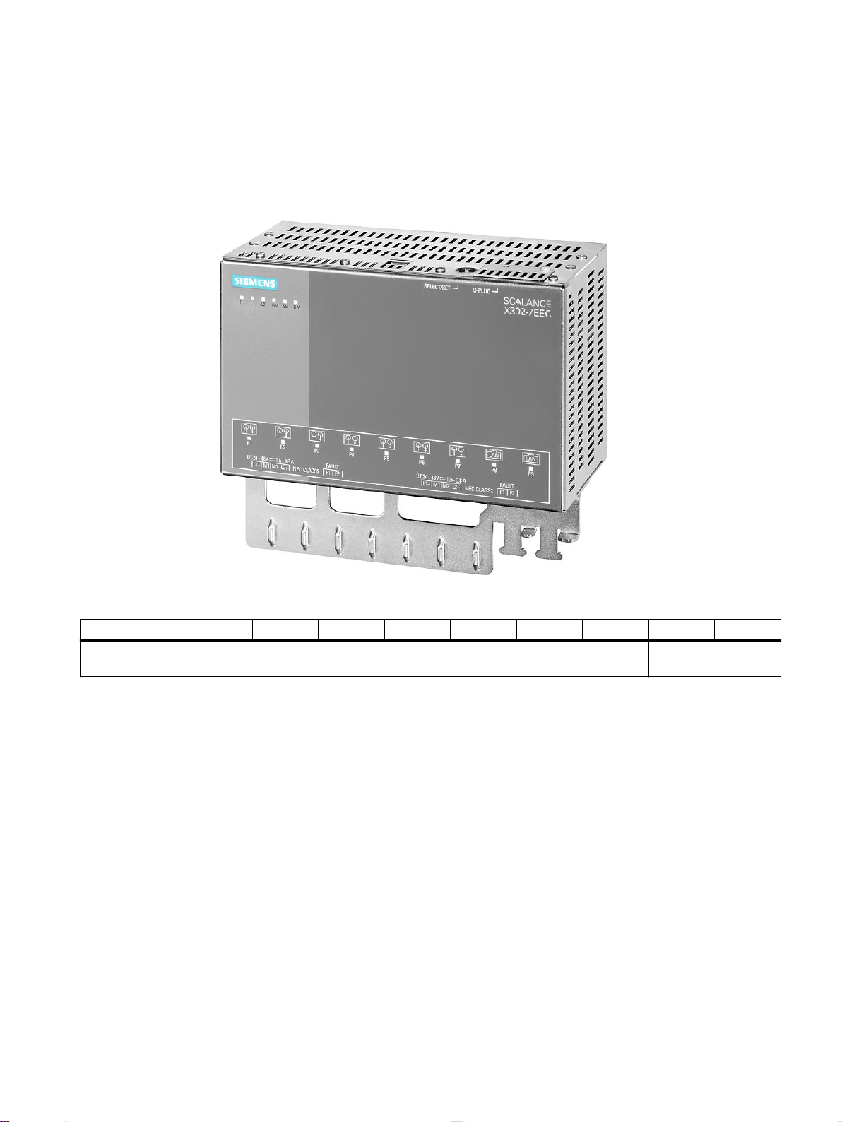
Ports of the X302-7EEC
The SCALANCE X302-7EEC has the following ports:
● 2 electrical gigabit ports (P8 to P9)
● 7 optical Fast Ethernet ports (P1 to P7)
Description of the device
4.2 Product properties and device views
Figure 4-3 SCALANCE X302-7EEC
Port number P1 P2 P3 P4 P5 P6 P7 P8 P9
Connection type Optical: Fast Ethernet Electrical: Gigabit
Ethernet
SCALANCE X-300EEC
Compact Operating Instructions, 11/2019, A5E02630809-14 23
Description of the device
4.2 Product properties and device views
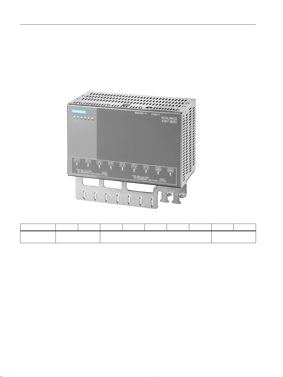
Ports of the X307-2EEC
The SCALANCE X307-2EEC has the following ports:
● 7 electrical ports (P3 to P9)
– 5 Fast Ethernet ports (P3 to P7)
– 2 gigabit ports (P8, P9)
● 2 optical Fast Ethernet ports (P1, P2)
Figure 4-4 SCALANCE X307-2EEC
Port number P1 P2 P3 P4 P5 P6 P7 P8 P9
Connection type Optical: Fast Ethernet Electrical: Fast Ethernet Electrical: Gigabit
Ethernet
SCALANCE X-300EEC
24 Compact Operating Instructions, 11/2019, A5E02630809-14

4.3 LED display
The "RM" LED for the "redundancy manager" function
The "RM" LED indicates whether or not the device is operating in the role of redundancy
manager and whether or not the ring is operating error-free.
LED color LED status Meaning
- off The device is not operating in the role of "redundancy manager".
green on The device is operating in the role of redundancy manager. The ring
is working without problems, monitoring is activated.
green flashes The device is operating in the role of redundancy manager. An in‐
terruption has been detected on the ring and the device has switched
through.
The "SB" LED for the standby function
This LED shows the status of the standby function.
Description of the device
4.3 LED display
LED color LED status Meaning
- off The standby function is disabled.
green on The standby function is enabled. The standby section is passive.
green flashes The standby function is enabled. The standby section is active.
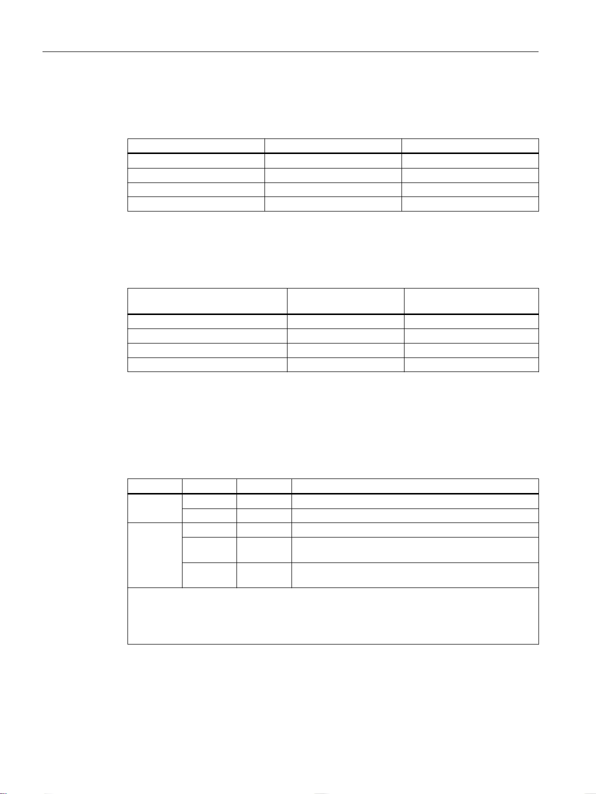
The "F" LED for the fault status
The "F" LED (fault) provides information on the error/fault status of the device. While the device
is starting up, this LED has the following meaning:
LED color LED status Meaning during the device startup
- off Device startup completed successfully.
red on Device startup not yet completed or a fault/error has occurred.
red flashes Bad firmware image.
During normal operation, the "F" LED provides the following information:
LED color LED status Meaning during operation
- off No operating problems.
red on The device has detected an error. The signaling contact opens.
SCALANCE X-300EEC
Compact Operating Instructions, 11/2019, A5E02630809-14 25
Description of the device
4.3 LED display
The "DM" LED for the display mode
The "DM" LED (Display Mode) indicates which of the four display modes A, B, C or D is
currently active. The meaning of the L1, L2 and P1, P2, ... LEDs depends on the display mode.
LED color LED status Meaning
- off Display mode A
green on Display mode B
orange on Display mode C
yellow/orange flashes Display mode D
Selecting the display mode
Press the SELECT/SET button to set the required display mode. If the SELECT/SET button is
not pressed for longer than a minute, the device automatically changes to display mode A.
Pressing the SELECT/SET button
starting at display mode A
- off Display mode A (default mode)
Press once lit green Display mode B
Press twice lit orange Display mode C
Press 3 times flashes yellow/orange Display mode D
The "L1" and "L2" or "L" LEDs for the power supply
Whereas on other devices, the "L1" and "L2" LEDs indicate information about the power, on the
SCALANCE X306-1LD FE, this is done by the "L" LED. A redundant power supply for this
device can be recognized by the color of the LED.
Meaning in display mode A, B or C
LED Color Status Meaning
L1 / L2 _ off Power supply L1 / L2 lower than 17 V *
green on Power supply L1 / L2 higher than 17 V *
L - off Power supplies L1 and L2 less than 17 V or not connected.
orange on Power supply L1 or L2 higher than 17 V
green on Power supplies L1 and L2 higher than 17 V
*) for the X‑300EEC the following applies:
● For devices with power supply unit 24 to 48 VDC: Limit voltage = 17 VDC
● For devices with a multiple range power supply unit 100 to 240 VAC / 60 to 250 VDC:
Limit voltage = 46.5 VDC or 80 VAC
Status of the "DM" LED Display mode
)
)
(no redundant supply).
(redundant supply).
SCALANCE X-300EEC
26 Compact Operating Instructions, 11/2019, A5E02630809-14
 Loading...