

Siemens SIMATIC NET SCALANCE X005, SIMATIC NET SCALANCE X-000, SIMATIC NET SCALANCE X005TS, SIMATIC NET SCALANCE X005EEC Operating Instructions Manual

SCALANCE X-000
___________________
___________________
___________________
___________________
___________________
___________________
___________________
___________________
___________________
SIMATIC NET
Industrial Ethernet switches
SCALANCE X-000
Operating Instructions
09/2016
C79000
-G8976-C344-02
Introduction
1
Network topologies
2
Description of the device
3
Mounting
4
Connecting up
5
Maintenance and
troubleshooting
6
Technical specifications
7
Approvals
8
Dimension drawings
9
Siemens AG
Division Process Industries and Drives
Postfach 48 48
90026 NÜRNBERG
GERMANY
C79000-G8976-C344-02
Ⓟ
09/2016 Subject to change
Copyright © Siemens AG 2010 - 2016.
All rights reserved
Legal information
Warning notice system
This manual contains notices you have to observe in order to ensure your personal safety, as well as to prevent
damage to property. The notices referring to your personal safety are highlighted in the manual by a safety alert
symbol, notices referring only to property damage have no safety alert symbol. These notices shown below are
graded according to the degree of danger.
DANGER
indicates that death or severe personal injury will result if proper precautions are not taken.
WARNING
indicates that death or severe personal injury may result if proper precautions are not taken.
CAUTION
indicates that minor personal injury can result if proper precautions are not taken.
NOTICE
indicates that property damage can result if proper precautions are not taken.
If more than one degree of danger is present, the warning notice representing the highest degree of danger will
be used. A notice warning of injury to persons with a safety alert symbol may also include a warning relating to
property damage.
Qualified Personnel
The product/system described in this documentation may be operated only by
personnel qualified
for the specific
task in accordance with the relevant documentation, in particular its warning notices and safety instructions.
Qualified personnel are those who, based on their training and experience, are capable of identifying risks and
avoiding potential hazards when working with these products/systems.
Proper use of Siemens products
Note the following:
WARNING
Siemens products may only be used for the applications described in the catalog and in the relevant technical
documentation. If products and components from other manufacturers are used, these must be recommended
or approved by Siemens. Proper transport, storage, installation, assembly, commissioning, operation and
maintenance are required to ensure that the products operate safely and without any problems. The permissible
ambient conditions must be complied with. The information in the relevant documentation must be observed.
Trademarks
All names identified by ® are registered trademarks of Siemens AG. The remaining trademarks in this publication
may be trademarks whose use by third parties for their own purposes could violate the rights of the owner.
Disclaimer of Liability
We have reviewed the contents of this publication to ensure consistency with the hardware and software
described. Since variance cannot be precluded entirely, we cannot guarantee full consistency. However, the
information in this publication is reviewed regularly and any necessary corrections are included in subsequent
editions.

SCALANCE X-000
Operating Instructions, 09/2016, C79000-G8976-C344-02
3
Table of contents
1 Introduction ............................................................................................................................................. 5
1.1 On the Operating Instructions ................................................................................................... 5
1.2 On the product .......................................................................................................................... 7
2 Network topologies ................................................................................................................................. 9
3 Description of the device ....................................................................................................................... 11
3.1 Overview SCALANCE X-000 .................................................................................................. 11
3.2 Product characteristics............................................................................................................ 12
3.3 TP ports (twisted pair) ............................................................................................................. 13
3.4 LEDs ....................................................................................................................................... 16
4 Mounting ............................................................................................................................................... 17
4.1 Safety notices for installation .................................................................................................. 17
4.2 Types of installation ................................................................................................................ 18
4.3 Installation on a DIN rail .......................................................................................................... 19
4.4 Installation on a standard rail .................................................................................................. 21
4.5 Wall mounting ......................................................................................................................... 22
5 Connecting up ....................................................................................................................................... 23
5.1 Safety when connecting up ..................................................................................................... 23
5.2 Wiring rules ............................................................................................................................. 25
5.3 Power supply .......................................................................................................................... 26
5.4 Grounding ............................................................................................................................... 27
5.5 IE FC RJ-45 Plug 180 ............................................................................................................. 28
6 Maintenance and troubleshooting .......................................................................................................... 31
7 Technical specifications ........................................................................................................................ 33
8 Approvals .............................................................................................................................................. 39
9 Dimension drawings .............................................................................................................................. 45
Index..................................................................................................................................................... 47

Table of contents
SCALANCE X-000
4 Operating Instructions, 09/2016, C79000-G8976-C344-02

SCALANCE X-000
Operating Instructions, 09/2016, C79000-G8976-C344-02
5
1
1.1
On the Operating Instructions
Purpose of the Operating Instructions
These operating instructions support you when commissioning the unmanaged Industrial
Ethernet entry level switches SCALANCE X-000.
Validity of the Operating Instructions
These operating instructions are valid for the following devices:
Device
Article number
SCALANCE X005 6GK5 005-0BA00-1AA3
6GK5 005-0BA10-1AA3
SCALANCE X005TS (Transportation
System)
6GK5 005-0BA00-1CA3
Further documentation
The "SIMATIC NET Industrial Ethernet Twisted Pair and Fiber Optic Networks" manual
contains additional information on other SIMATIC NET products that you can operate along
with the SCALANCE X-000 IE switches in an Industrial Ethernet network.
You can order the manual "SIMATIC NET Industrial Twisted Pair and Fiber Optic Networks",
release 05/2001, using the following order numbers:
6GK1970-1BA10-0AA0 German
6GK1970-1BA10-0AA1 English
6GK1970-1BA10-0AA2 French
6GK1970-1BA10-0AA4 Italian
You will also find this network manual on the Internet pages of Service & Support under the
following entry ID: 1172207 (http://support.automation.siemens.com/WW/view/en/1172207
).
You will find further information in the "System Manual Industrial Ethernet" in the Manual
Collection.
You will find further information on the SCALANCE system on the Internet at
www.siemens.com/scalance (www.siemens.com/scalance
).
Audience
These Operating Instructions are intended for persons who commission networks with the IE
switches of the SCALANCE X-000 product line.

Introduction
1.1 On the Operating Instructions
SCALANCE X-000
6 Operating Instructions, 09/2016, C79000-G8976-C344-02
SIMATIC NET glossary
Explanations of many of the specialist terms used in this documentation can be found in the
SIMATIC NET glossary.
You will find the SIMATIC NET glossary on the Internet at the following address:
50305045 (http://support.automation.siemens.com/WW/view/en/50305045
)
Security information
Siemens provides products and solutions with industrial security functions that support the
secure operation of plants, solutions, machines, equipment and/or networks. They are
important components in a holistic industrial security concept. With this in mind, Siemens’
products and solutions undergo continuous development. Siemens recommends strongly
that you regularly check for product updates.
For the secure operation of Siemens products and solutions, it is necessary to take suitable
preventive action (e.g. cell protection concept) and integrate each component into a holistic,
state-of-the-art industrial security concept. Third-party products that may be in use should
also be considered. You will find more information about Industrial Security in:
Industrial security (http://www.siemens.com/industrialsecurity
)
To stay informed about product updates as they occur, sign up for a product-specific
newsletter. You will find more information about this in
Product support (https://support.industry.siemens.com/cs/ww/en/ps/15247/pm
)

Introduction
1.2 On the product
SCALANCE X-000
Operating Instructions, 09/2016, C79000-G8976-C344-02
7
1.2
On the product
What is possible?
The SCALANCE X-000 IE switches allow the cost-effective installation of small Industrial
Ethernet linear bus or star structures with switching functionality. The devices are designed
for installation in a cabinet.
Note
It is not possible to use a SCALANCE
X-000 in a redundant ring because it does not support
redundancy.
Note
If devices are supplied over long 24 V power supply lines or
networks, measures are
necessary to prevent interference by strong electromagnetic pulses on the supply lines.
These can result, for example, due to lightning or switching of large inductive loads.
One of the tests used to attest the immunity of these dev
ices to electromagnetic interference
is the "surge immunity test" according to EN 61000
-4-5. This test requires overvoltage
protection for the power supply lines. A suitable device is, for example, the Dehn Blitzductor
BVT AVD 24 V type no. 918 422 or a co
mparable protective element.
Manufacturer:
DEHN+SÖHNE GmbH+Co.KG Hans Dehn Str.1 Postfach 1640 D
-92306 Neumarkt,
Germany
Components of the product
The following components are supplied with a SCALANCE X-000:
● IE switch SCALANCE X-000
● 2-terminal plug-in block (power supply)
● Product information
Accessories
Component
Packaging unit
Article number
IE FC Stripping Tool
1
6GK1 901-1GA00
IE FC blade cassettes
1
6GK1 901-1GB00
IE FC TP standard cable GP
1
6XV1 840 2AH10
IE FC TP trailing cable
1
6XV1 840-3AH10
IE FC TP marine cable
1
6XV1 840-4AH10
IE FC TP trailing cable GP
1
6XV1 870-2D
IE FC TP flexible cable GP
1
6XV1 870-2B
IE FC RJ-45 Plug 180
1
6GK1 901-1BB10-2AA0
Introduction
1.2 On the product
SCALANCE X-000
8 Operating Instructions, 09/2016, C79000-G8976-C344-02
Component
Packaging unit
Article number
IE FC RJ-45 Plug 180
10
6GK1 901-1BB10-2AB0
IE FC RJ-45 Plug 180 50 6GK1 901-1BB10-2AE0
Unpacking and checking
WARNING
Do not use any parts that show evidence of damage
If you use damaged parts, there is no guarantee that the device will function according to
the specification.
If you use damaged parts, this can lead to the following problems:
• Injury to persons
• Loss of the approvals
• Violation of the EMC regulations
• Damage to the device and other components
Use only undamaged parts.
1. Make sure that the package is complete.
2. Check all the parts for transport damage.
Warning triangle on the type plate.
This warning triangle on the type plate refers to the safety-relevant notes in the
documentation.
Read the operating instructions and note the safety-relevant information.
SCALANCE X-000
Operating Instructions, 09/2016, C79000-G8976-C344-02
9
2
Switching technology allows extensive networks to be set up with numerous nodes and
simplifies network expansion.
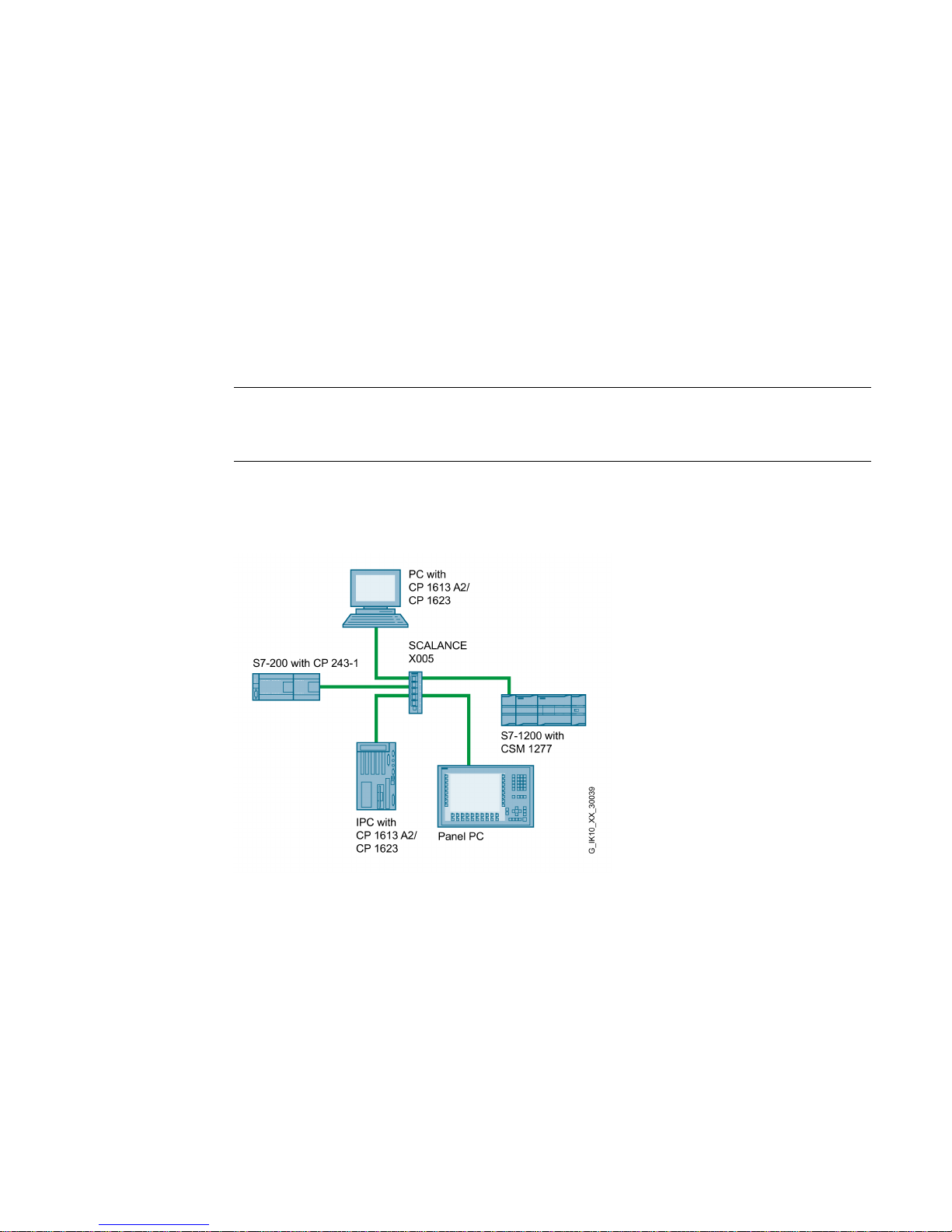
Which topologies can be implemented?
Using the SCALANCE X-000 IE switches, you can implement star topologies.
Note
Keep to the maximum permitted cable lengths of the devices you are using. You will find the
permitted cable lengths in the section "
Technical specifications (Page 33)".
Star topology
Figure 2-1 Example of a star topology with SCALANCE X-000

Network topologies
SCALANCE X-000
10 Operating Instructions, 09/2016, C79000-G8976-C344-02

SCALANCE X-000
Operating Instructions, 09/2016, C79000-G8976-C344-02
11
3
3.1
Overview SCALANCE X-000
Table 3- 1 Overview of the product characteristics
X005
X005TS
SIMATIC environment + +
Diagnostics LED
+
+
24 VDC + +
2 x 24 VDC - -
Compact housing
(securing collar, etc.)
+ +
Signaling contact + on-site operation
-
-
Diagnostics: Web, SNMP, PROFINET
-
-
C-PLUG - -
Ring redundancy with RM
-
-
Passive ring redundancy
-
-
Standby redundancy
-
-
IRT capability - -
Fast learning - -
Passive listening
-
-
Log table - -
SNTP + SICLOCK
-
-
Cut Through - -
Table 3- 2 Overview of the connection options
X005
X005TS
TP (RJ-45)
Fast Ethernet 10 / 100 Mbps
5 5
Description of the device
3.2 Product characteristics
SCALANCE X-000
12 Operating Instructions, 09/2016, C79000-G8976-C344-02
3.2
Product characteristics
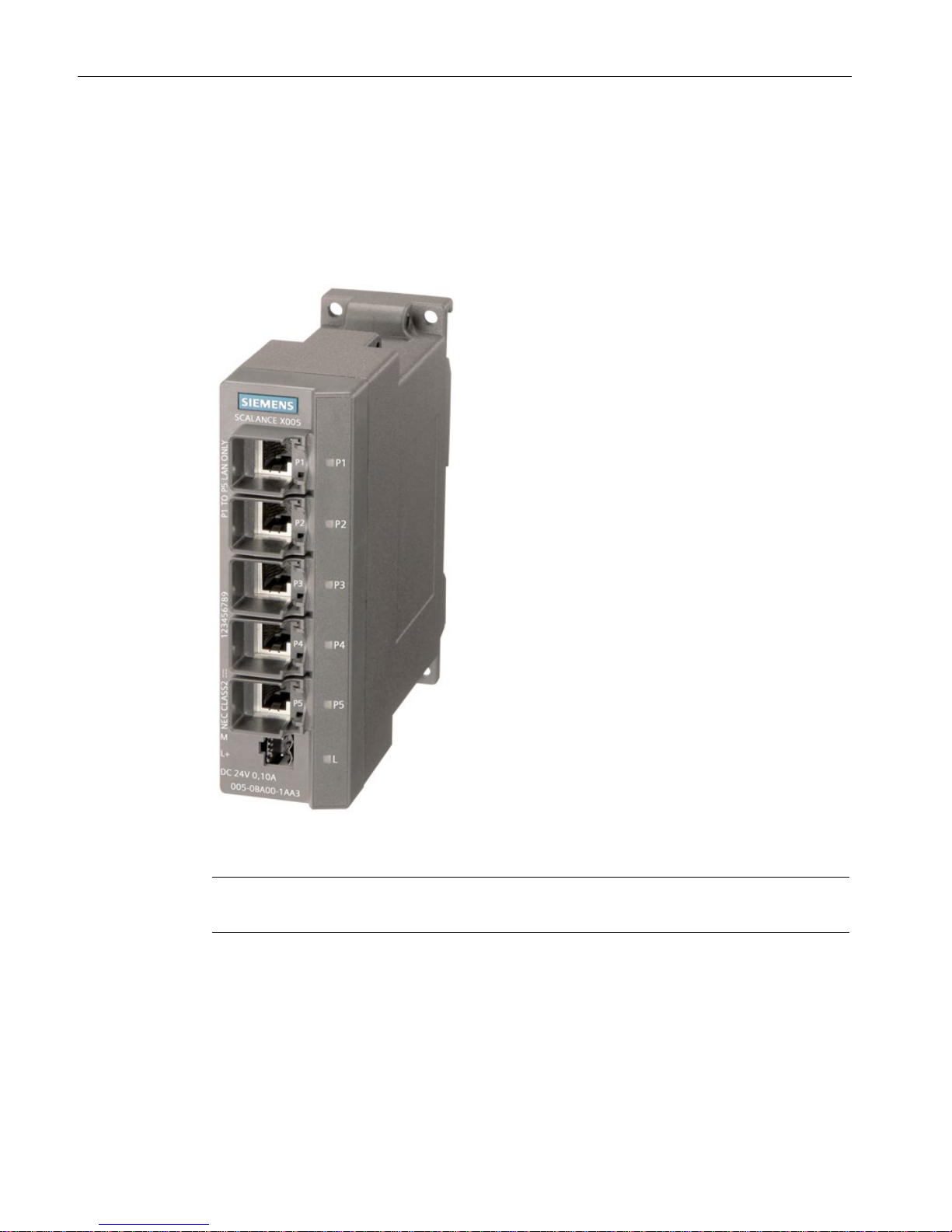
Possible attachments
The SCALANCE X-000 has five RJ-45 jacks for connection of end devices or other network
segments.
Figure 3-1 SCALANCE X005
Note
The SCALANCE X005 shown above has the same construction as the SCALANCE X005TS.
Description of the device
3.3 TP ports (twisted pair)
SCALANCE X-000
Operating Instructions, 09/2016, C79000-G8976-C344-02
13
3.3
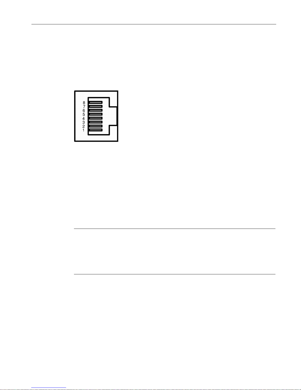
TP ports (twisted pair)
RJ-45 connector pinout
With SCALANCE X-000, the twisted-pair ports are designed as RJ-45 jacks with MDI-X pin
assignment (Medium Dependent Interface Autocrossover) of a network component.
Pin number
Assignment
Pin 8
n. c.
Pin 7
n. c.
Pin 6
TD-
Pin 5
n. c.
Pin 4
n. c.
Pin 3
TD+
Pin 2
RD-
Pin 1
RD+
Note
Permitted cable lengths
TP cords or TP
-XP cords with a maximum length of 10 m can be connected to the TP port
with RJ
-45 jacks.
With the IE FC cables and IE FC RJ
-45 plugs 180, an overall cable length of a maximum of
100 m is permitted between two devices depending on the cable
type.
Autonegotiation
With the autonegotiation mechanism, repeaters and end devices can automatically
determine the transmission speed and the transmission mode of the partner port. This
makes it possible to configure different devices automatically.

Description of the device
3.3 TP ports (twisted pair)
SCALANCE X-000
14 Operating Instructions, 09/2016, C79000-G8976-C344-02
Two components connected to a link segment can exchange information about the data
transfer and can adapt their settings to each other. The mode with the highest possible
speed is set.
Note
Setting ports with a fixed configuration
Devices not supporting autonegotiation must be set permanently to 100
Mbps half duplex or
10
Mbps half duplex.
Auto polarity exchange
If the pair of receiving cables is connected incorrectly (RD+ and RD- interchanged), the
polarity is adapted automatically.
Note
The SCALANCE
X-000 IE switches are plug-and-play devices that require no settings during
commissioning.
MDI / MDI-X autocrossover function
With the MPI/MDI-X autocrossover function, the send and receive contacts of an Ethernet
port are assigned automatically. The assignment depends on the cable with which the
communications partner is connected. This means that it does not matter whether the port is
connected using a patch cable or crossover cable. This prevents malfunctions resulting from
mismatching send and receive lines. This makes installation much easier for the user.
The SCALANCE X-000 devices support the MDI / MDI-X autocrossover function.
Insulation between the TP ports
NOTICE
Formation of loops
Note that the direct connection of two ports or accidental connection over several switches
causes an illegal loop that can cause network overload and failure.
Devices with port groups
On the following devices, the ports are divided into port groups.
● SCALANCE X005
6GK5 005-0BA00-1AA3
● SCALANCE X005TS
6GK5 005-0BA00-1CA3

Description of the device
3.3 TP ports (twisted pair)
SCALANCE X-000
Operating Instructions, 09/2016, C79000-G8976-C344-02
15
There are two TP port groups:
Group 1: P1
Group2: P2 to P5
Between ports of different port groups, an insulation voltage of 1.5 kV is adhered to
(corresponds to IEEE802.3, Chapter 33.4.1.1, Environment B), e.g. between P1 and P2.
The requirements for Environment A are met between ports of the same group, e.g. between
P2 and P5.
Devices without port groups
The following devices do not have port groups:
● SCALANCE X005
6GK5 005-0BA10-1AA3
The requirements for Environment A are met between all ports.
 Loading...