

Siemens SIMATIC NET SCALANCE W721-1, SIMATIC NET SCALANCE W761-1, SIMATIC NET SCALANCE W760, SIMATIC NET SCALANCE W720, SIMATIC NET SCALANCE W722-1 Configuration Manual

SCALANCE W760/W720 to IEEE
802.11n Web Based Management
___________________
___________________
___________________
___________________
___________________
___________________
___________________
___________________
___________________
___________________
___________________
SIMATIC NET
Industrial Wireless LAN
SCALANCE W760/W720 to IEEE
802.11n Web Based Management
Configuration Manual
11/2014
C79000
Introduction
1
Description
2
Technical basics
3
Assignment of an IP address
4
Configuring with Web Based
Management
5
Upkeep and maintenance
6
Troubleshooting/FAQ
7
Appendix A
A
Appendix B
B
Appendix C
C
Appendix D
D
-G8976-C350-03

Siemens AG
Division Digital Factory
Postfach 48 48
90026 NÜRNBERG
GERMANY
C79000-G8976-C350-03
Ⓟ
Copyright © Siemens AG 2013 - 2014.
All rights reserved
Legal information
Warning notice system
DANGER
indicates that death or severe personal injury will result if proper precautions are not taken.
WARNING
indicates that death or severe personal injury may result if proper precautions are not taken.
CAUTION
indicates that minor personal injury can result if proper precautions are not taken.
NOTICE
indicates that property damage can result if proper precautions are not taken.
Qualified Personnel
personnel qualified
Proper use of Siemens products
WARNING
Siemens products may only be used for the applications described in the catalog and in the relevant technical
maintenance are required to ensure that the products operate safely and without any problems. The permissible
ambient conditions must be complied with. The information in the relevant documentation must be observed.
Trademarks
Disclaimer of Liability
This manual contains notices you have to observe in order to ensure your personal safety, as well as to prevent
damage to property. The notices referring to your personal safety are highlighted in the manual by a safety alert
symbol, notices referring only to property damage have no safety alert symbol. These notices shown below are
graded according to the degree of danger.
If more than one degree of danger is present, the warning notice representing the highest degree of danger will
be used. A notice warning of injury to persons with a safety alert symbol may also include a warning relating to
property damage.
The product/system described in this documentation may be operated only by
task in accordance with the relevant documentation, in particular its warning notices and safety instructions.
Qualified personnel are those who, based on their training and experience, are capable of identifying risks and
avoiding potential hazards when working with these products/systems.
Note the following:
documentation. If products and components from other manufacturers are used, these must be recommended
or approved by Siemens. Proper transport, storage, installation, assembly, commissioning, operation and
All names identified by ® are registered trademarks of Siemens AG. The remaining trademarks in this publication
may be trademarks whose use by third parties for their own purposes could violate the rights of the owner.
We have reviewed the contents of this publication to ensure consistency with the hardware and software
described. Since variance cannot be precluded entirely, we cannot guarantee full consistency. However, the
information in this publication is reviewed regularly and any necessary corrections are included in subsequent
editions.
for the specific
12/2014 Subject to change

Table of contents
1 Introduction ............................................................................................................................................. 7
2 Description ............................................................................................................................................ 11
3 Technical basics ................................................................................................................................... 23
4 Assignment of an IP address ................................................................................................................. 33
5 Configuring with Web Based Management ............................................................................................ 37
1.1 Information on the Configuration Manual.................................................................................. 7
1.2 Security information .................................................................................................................. 9
1.3 Type designations ..................................................................................................................... 9
2.1 Network structures .................................................................................................................. 11
2.2 Possible applications of SCALANCE W700 devices .............................................................. 15
2.3 Product characteristics............................................................................................................ 16
2.4 IEEE 802.11n .......................................................................................................................... 18
2.5 Requirements for installation and operation ........................................................................... 21
3.1 VLAN ....................................................................................................................................... 23
3.2 MAC-based communication .................................................................................................... 23
3.3 iPCF / iPCF-MC ...................................................................................................................... 25
3.4 NAT/NAPT .............................................................................................................................. 27
3.5 SNMP ...................................................................................................................................... 28
3.6 Spanning Tree ........................................................................................................................ 30
3.6.1 RSTP, MSTP, CIST ................................................................................................................ 31
4.1 Structure of an IP address ...................................................................................................... 33
4.2 Initial assignment of an IP address ......................................................................................... 34
4.3 Address assignment with DHCP ............................................................................................. 34
4.4 Address assignment with the Primary Setup Tool .................................................................. 35
4.5 Address assignment with STEP 7 .......................................................................................... 36
5.1 Web Based Management ....................................................................................................... 37
5.2 Login ....................................................................................................................................... 38
5.3 "Wizard" menu ........................................................................................................................ 41
5.3.1 Basic Wizard ........................................................................................................................... 41
5.3.1.1 System Settings ...................................................................................................................... 42
5.3.1.2 Country Settings ..................................................................................................................... 44
5.3.1.3 IP Address Settings ................................................................................................................ 45
5.3.1.4 Management Interfaces .......................................................................................................... 46
SCALANCE W760/W720 to IEEE 802.11n Web Based Management
Configuration Manual, 11/2014, C79000-G8976-C350-03
3

Table of contents
5.3.1.5 Antenna Settings .................................................................................................................... 47
5.3.1.6 Radio Settings ........................................................................................................................ 48
5.3.1.7 Access Point Settings ............................................................................................................ 50
5.3.1.8 Client Settings ........................................................................................................................ 51
5.3.1.9 Client Allowed Channel Settings ............................................................................................ 53
5.3.1.10 Security Settings .................................................................................................................... 55
5.3.1.11 Dot1x Supplicant Settings ...................................................................................................... 57
5.3.1.12 Dot1x Radius Server Settings ................................................................................................ 58
5.3.1.13 Summary of Settings .............................................................................................................. 59
5.4 "Information" menu................................................................................................................. 60
5.4.1 I&M ......................................................................................................................................... 60
5.4.2 Start Page .............................................................................................................................. 61
5.4.3 Versions ................................................................................................................................. 66
5.4.4 ARP Table .............................................................................................................................. 67
5.4.5 Log Tables ............................................................................................................................. 68
5.4.5.1 Event Log ............................................................................................................................... 68
5.4.5.2 WLAN Authentication Log ...................................................................................................... 71
5.4.6 Faults ..................................................................................................................................... 72
5.4.7 Redundancy ........................................................................................................................... 73
5.4.8 Ethernet Statistics .................................................................................................................. 77
5.4.8.1 Interface statistics .................................................................................................................. 77
5.4.8.2 Packet Size ............................................................................................................................ 78
5.4.8.3 Packet Type ...........................................................................................................................
79
5.4.8.4 Packet Error ........................................................................................................................... 80
5.4.9 Learning Table ....................................................................................................................... 81
5.4.10 DHCP Server ......................................................................................................................... 82
5.4.11 WLAN ..................................................................................................................................... 84
5.4.11.1 Overview AP .......................................................................................................................... 84
5.4.11.2 Client List ............................................................................................................................... 86
5.4.11.3 WDS List ................................................................................................................................ 87
5.4.11.4 Overlap AP ............................................................................................................................. 89
5.4.11.5 Overview Client ...................................................................................................................... 90
5.4.11.6 Available AP ........................................................................................................................... 92
5.4.11.7 IP Mapping Table ................................................................................................................... 94
5.4.12 WLAN Statistics ..................................................................................................................... 96
5.4.12.1 Errors ..................................................................................................................................... 96
5.4.12.2 Management Sent .................................................................................................................. 98
5.4.12.3 Management Received ........................................................................................................ 100
5.4.12.4 Data Sent ............................................................................................................................. 102
5.4.12.5 Data Received...................................................................................................................... 104
5.5 "System" menu ..................................................................................................................... 106
5.5.1 Configuration ........................................................................................................................ 106
5.5.2 General ................................................................................................................................ 109
5.5.2.1 Device .................................................................................................................................. 109
5.5.2.2 Coordinates .......................................................................................................................... 110
5.5.3 Agent IP ............................................................................................................................... 112
5.5.4 DNS Client ........................................................................................................................... 114
5.5.5 Restart .................................................................................................................................. 116
5.5.6 Commit Control .................................................................................................................... 118
5.5.7 Load&Save ........................................................................................................................... 119
5.5.7.1 HTTP .................................................................................................................................... 121
SCALANCE W760/W720 to IEEE 802.11n Web Based Management
4 Configuration Manual, 11/2014, C79000-G8976-C350-03

Table of contents
5.5.7.2 TFTP ..................................................................................................................................... 123
5.5.7.3 Passwords ............................................................................................................................ 125
5.5.8 Events ................................................................................................................................... 127
5.5.8.1 Configuration ......................................................................................................................... 127
5.5.8.2 Severity ................................................................................................................................. 129
5.5.9 SMTP Client .......................................................................................................................... 130
5.5.10 DHCP .................................................................................................................................... 132
5.5.10.1 DHCP Client .......................................................................................................................... 132
5.5.10.2 DHCP server ......................................................................................................................... 134
5.5.10.3 DHCP Options ...................................................................................................................... 136
5.5.10.4 Static Leases ........................................................................................................................ 138
5.5.11 SNMP .................................................................................................................................... 139
5.5.11.1 General ................................................................................................................................. 139
5.5.11.2 Traps ..................................................................................................................................... 141
5.5.11.3 v3 Groups ............................................................................................................................. 142
5.5.11.4 v3 Users ................................................................................................................................ 145
5.5.12 System Time ......................................................................................................................... 147
5.5.12.1 Manual Setting ...................................................................................................................... 147
5.5.12.2 DST Overview ....................................................................................................................... 149
5.5.12.3 DST Configuration ................................................................................................................ 150
5.5.12.4 SNTP Client .......................................................................................................................... 154
5.5.12.5 NTP Client ............................................................................................................................. 157
5.5.12.6 SIMATIC Time Client ............................................................................................................ 159
5.5.13 Auto Logout ........................................................................................................................... 160
5.5.14 Syslog Client ......................................................................................................................... 160
5.5.15 Fault Monitoring .................................................................................................................... 162
5.5.15.1 Power Supply ........................................................................................................................ 162
5.5.15.2 Link Change .......................................................................................................................... 163
5.5.16 PNIO ..................................................................................................................................... 164
5.5.17 Ping ....................................................................................................................................... 166
5.6 "Interfaces" menu .................................................................................................................. 167
5.6.1 Ethernet ................................................................................................................................ 167
5.6.1.1 Ports Overview ...................................................................................................................... 167
5.6.1.2 Configuration ......................................................................................................................... 168
5.6.2 WLAN .................................................................................................................................... 170
5.6.2.1 Basic ..................................................................................................................................... 170
5.6.2.2 Advanced .............................................................................................................................. 174
5.6.2.3 Antennas ............................................................................................................................... 175
5.6.2.4 Allowed Channels ................................................................................................................. 178
5.6.2.5 802.11n ................................................................................................................................. 179
5.6.2.6 AP ......................................................................................................................................... 181
5.6.2.7 AP WDS ................................................................................................................................ 184
5.6.2.8 AP 802.11a/b/g Rates ........................................................................................................... 185
5.6.2.9 AP 802.11n Rates ................................................................................................................. 188
5.6.2.10 Client ..................................................................................................................................... 190
5.6.2.11 Signal Recorder .................................................................................................................... 193
5.7 "Layer 2" menu ..................................................................................................................... 198
5.7.1 VLAN ..................................................................................................................................... 198
5.7.1.1 General ................................................................................................................................. 198
5.7.1.2 Port Based ............................................................................................................................ 200
5.7.2 Dynamic MAC Aging ............................................................................................................. 202
SCALANCE W760/W720 to IEEE 802.11n Web Based Management
Configuration Manual, 11/2014, C79000-G8976-C350-03
5

Table of contents
6 Upkeep and maintenance .................................................................................................................... 235
7 Troubleshooting/FAQ ........................................................................................................................... 237
A Appendix A .......................................................................................................................................... 241
B Appendix B .......................................................................................................................................... 243
C Appendix C .......................................................................................................................................... 245
D Appendix D .......................................................................................................................................... 247
Index ................................................................................................................................................... 253
5.7.3 Spanning Tree...................................................................................................................... 203
5.7.3.1 General ................................................................................................................................ 203
5.7.3.2 CIST General ....................................................................................................................... 204
5.7.3.3 CIST Port ............................................................................................................................. 207
5.7.3.4 MST general ......................................................................................................................... 210
5.7.3.5 MST Port .............................................................................................................................. 212
5.7.4 DCP Forwarding................................................................................................................... 214
5.7.5 LLDP .................................................................................................................................... 215
5.8 "Layer 3" menu ..................................................................................................................... 216
5.8.1 NAT ...................................................................................................................................... 216
5.8.1.1 Basic .................................................................................................................................... 216
5.8.1.2 NAPT .................................................................................................................................... 218
5.9 "Security" menu .................................................................................................................... 220
5.9.1 Passwords ............................................................................................................................ 220
5.9.2 WLAN ................................................................................................................................... 221
5.9.2.1 Basic .................................................................................................................................... 221
5.9.2.2 AP Communication .............................................................................................................. 224
5.9.2.3 AP RADIUS Authenticator ................................................................................................... 225
5.9.2.4 Client RADIUS Supplicant ................................................................................................... 227
5.9.2.5 Keys ..................................................................................................................................... 228
5.9.3 Management ACL ................................................................................................................ 229
5.10 "iFeatures" menu .................................................................................................................. 232
5.10.1 iPCF ..................................................................................................................................... 232
5.10.2 iPCF-MC .............................................................................................................................. 233
6.1 Firmware update - via WBM ................................................................................................ 235
6.2 Restoring the default parameter settings ............................................................................. 236
7.1 Firmware update via WBM or CLI not possible ................................................................... 237
7.2 Disrupted data transmission due to the received power being too high .............................. 238
7.3 Compatibility with predecessor products ............................................................................. 239
7.4 Instructions for secure network design ................................................................................ 239
A.1 Supported MIB files .............................................................................................................. 241
B.1 Private MIB variables ........................................................................................................... 243
C.1 Underlying standards ........................................................................................................... 245
D.1 Messages in the event log ................................................................................................... 247
D.2 Messages in the WLAN authentication log .......................................................................... 251
SCALANCE W760/W720 to IEEE 802.11n Web Based Management
6 Configuration Manual, 11/2014, C79000-G8976-C350-03

1
1.1
Information on the Configuration Manual
Validity of the configuration manual
Purpose of the Configuration Manual
Orientation in the documentation
This Configuration Manual covers the following products:
● SCALANCE W721-1 RJ-45
● SCALANCE W722-1 RJ-45
● SCALANCE W761-1 RJ-45
This Configuration Manual applies to the following software version:
● SCALANCE W700 firmware as of Version V 5.00
This Configuration Manual is intended to provide you with the information you require to
commission and operate devices correctly. It explains how to configure the devices and how
to integrate them in a WLAN network.
The operating instructions for the corresponding device describe how to install and connect
up the devices correctly.
Apart from the Configuration Manual you are currently reading, the following documentation
is also available from SIMATIC NET on the topic of Industrial Wireless LANs:
● Configuration Manual: SCALANCE W760 / W720 Command Line Interface
This document contains the CLI commands that are supported by SCALANCE W700
devices.
● Performance data 802.11 abgn SCALANCE W760/W720
This document contains information about the frequency, modulation, transmit power and
receiver sensitivity.
● Operating Instructions SCALANCE W721-1 / W722-1 / W761-1
This document contains information on installing and connecting up the following
products and their approvals.
– SCALANCE W721-1 RJ-45
– SCALANCE W722-1 RJ-45
– SCALANCE W761-1 RJ-45
SCALANCE W760/W720 to IEEE 802.11n Web Based Management
Configuration Manual, 11/2014, C79000-G8976-C350-03
7

Introduction
SIMATIC NET manuals
1.1 Information on the Configuration Manual
● System Manual Structure of an Industrial Wireless LAN
Apart from the description of the physical basics and a presentation of the main IEEE
standards, this also contains information on data security and a description of the
industrial applications of wireless LAN.
You should read this manual if you want to set up WLAN networks with a more complex
structure (not simply a connection between two devices).
● System manual RCoax
This system manual contains both an explanation of the fundamental technical aspects
as well as a description of the individual RCoax components and their functionality.
Installation/commissioning and connection of RCoax components and their operating
principle are explained. The possible applications of the various SIMATIC NET
components are described.
● System manual - Passive Network Components IWLAN
This system manual explains the entire IWLAN cabling that you require for your IWLAN
application. For a flexible combination and installation of the individual IWLAN
components both indoors and outdoors, a wide ranging selection of compatible coaxial
accessories are available. The system manual also covers connecting cables as well as a
variety of plug-in connectors, lightning protectors, a power splitter and an attenuator.
You will find SIMATIC NET manuals on the Internet pages of Siemens Industry Online
Support:
● Using the search function:
support.automation.siemens.com
(
http://support.automation.siemens.com/WW/llisapi.dll?func=cslib.csinfo2&aktprim=99&la
ng=en)
Enter the entry ID of the relevant manual as the search item.
● In the navigation panel on the left-hand side in the area "Industrial Communication":
Industrial communication
(
http://support.automation.siemens.com/WW/llisapi.dll?func=cslib.csinfo&lang=de&siteid=
csius&aktprim=0&extranet=standard&viewreg=WW&objid=10805878&treeLang=en)
Go to the required product group and make the following settings:
tab "Entry list", Entry type "Manuals"
You will find the documentation for the SIMATIC NET products relevant here on the data
storage medium that ships with some products:
● Product CD / product DVD
● SIMATIC NET Manual Collection
● SIMATIC NET IWLAN CD
SCALANCE W760/W720 to IEEE 802.11n Web Based Management
8 Configuration Manual, 11/2014, C79000-G8976-C350-03

Introduction
Further documentation
1.2
Security information
1.3
Type designations
Abbreviations used
Product group
The designation . . .
stands for . . .
Product name
Access point
W761-1
SCALANCE W761-1 RJ-45
Client
W721-1
SCALANCE W721-1 RJ-45
Client with iFeatures
W722-1
SCALANCE W722-1 RJ-45
SCALANCE W722-1 RJ-45
1.2 Security information
The "SIMATIC NET Industrial Ethernet Network Manual" contains information on other
SIMATIC NET products that you can operate along with the devices of this product line in an
Industrial Ethernet network. There, you will find among other things optical performance data
of the communication partners that you require for the installation.
The "SIMATIC NET Industrial Ethernet Network Manual" can be found on the Internet pages
of Siemens Industry Online Support under the following entry ID:
)
27069465 (http://support.automation.siemens.com/WW/view/en/27069465
Siemens provides automation and drive products with industrial security functions that
support the secure operation of plants or machines. They are an important component in a
holistic industrial security concept. With this in mind, our products undergo continuous
development. We therefore recommend that you keep yourself informed with respect to our
product updates. Please find further information and newsletters on this subject at:
http://support.automation.siemens.com.
To ensure the secure operation of a plant or machine it is also necessary to take suitable
preventive action (e.g. cell protection concept) and to integrate the automation and drive
components into a state-of-the-art holistic industrial security concept for the entire plant or
machine. Any third-party products that may be in use must also be taken into account.
Please find further information at: http://www.siemens.com/industrialsecurity
The information in the manuals for the SCALANCE W700 product family often applies to
more than one product variant. In such situations, the designations of the products are
shortened to avoid having to list all the type designations. The following table shows how the
abbreviations relate to the product variants.
All SCALANCE W devices W700 SCALANCE W761-1 RJ-45
SCALANCE W721-1 RJ-45
SCALANCE W760/W720 to IEEE 802.11n Web Based Management
Configuration Manual, 11/2014, C79000-G8976-C350-03
9
Introduction
SIMATIC NET glossary
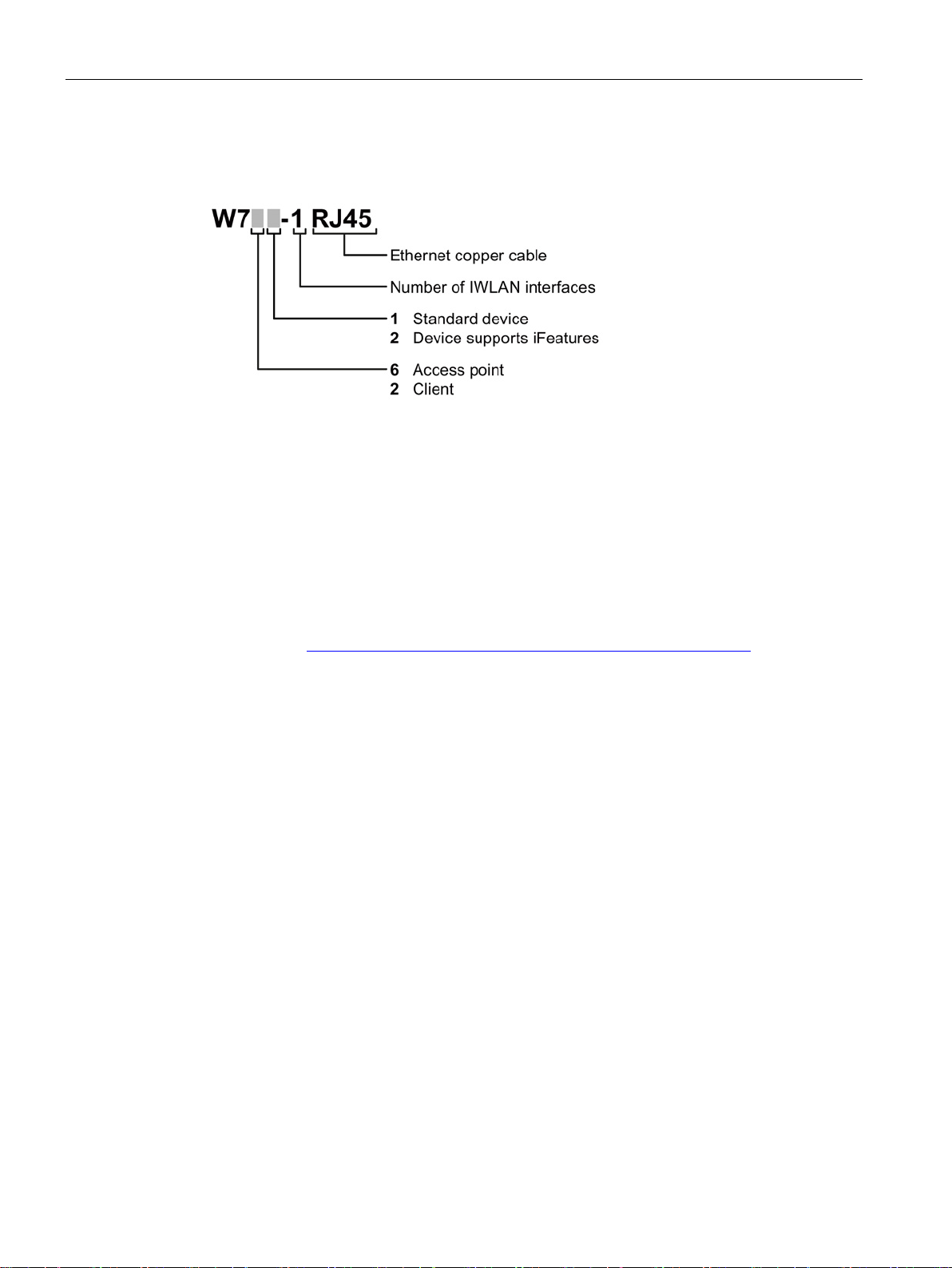
1.3 Type designations
The type designation of a SCALANCE W700 is made up of several parts that have the
following meaning:
Explanations of many of the specialist terms used in this documentation can be found in the
SIMATIC NET glossary.
You will find the SIMATIC NET glossary here:
● SIMATIC NET Manual Collection or product DVD
The DVD ships with certain SIMATIC NET products.
● On the Internet under the following entry ID:
50305045 (http://support.automation.siemens.com/WW/view/en/50305045
)
SCALANCE W760/W720 to IEEE 802.11n Web Based Management
10 Configuration Manual, 11/2014, C79000-G8976-C350-03
2
2.1
Network structures
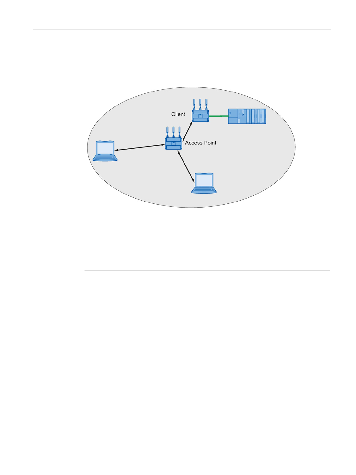
Standalone configuration with access point
The following article deals with the setting up of various network structures using access
points and clients. A client is also an access point in client mode.
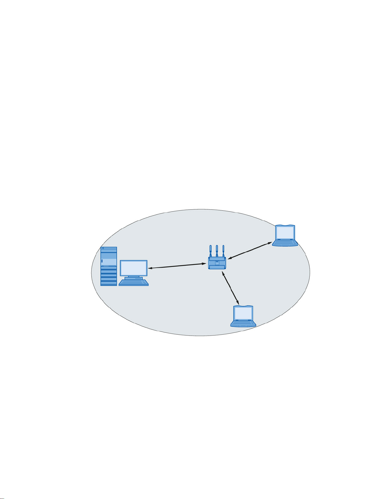
This configuration does not require a server and the access point does not have a
connection to a wired Ethernet. Within its transmission range, the access point forwards data
from one WLAN node to another.
The wireless network has a unique name. All the devices exchanging data within this
network must be configured with this name.
Figure 2-1 Standalone configuration of an access point. The gray area symbolizes the wireless
range of the access point.
SCALANCE W760/W720 to IEEE 802.11n Web Based Management
Configuration Manual, 11/2014, C79000-G8976-C350-03
11

Description
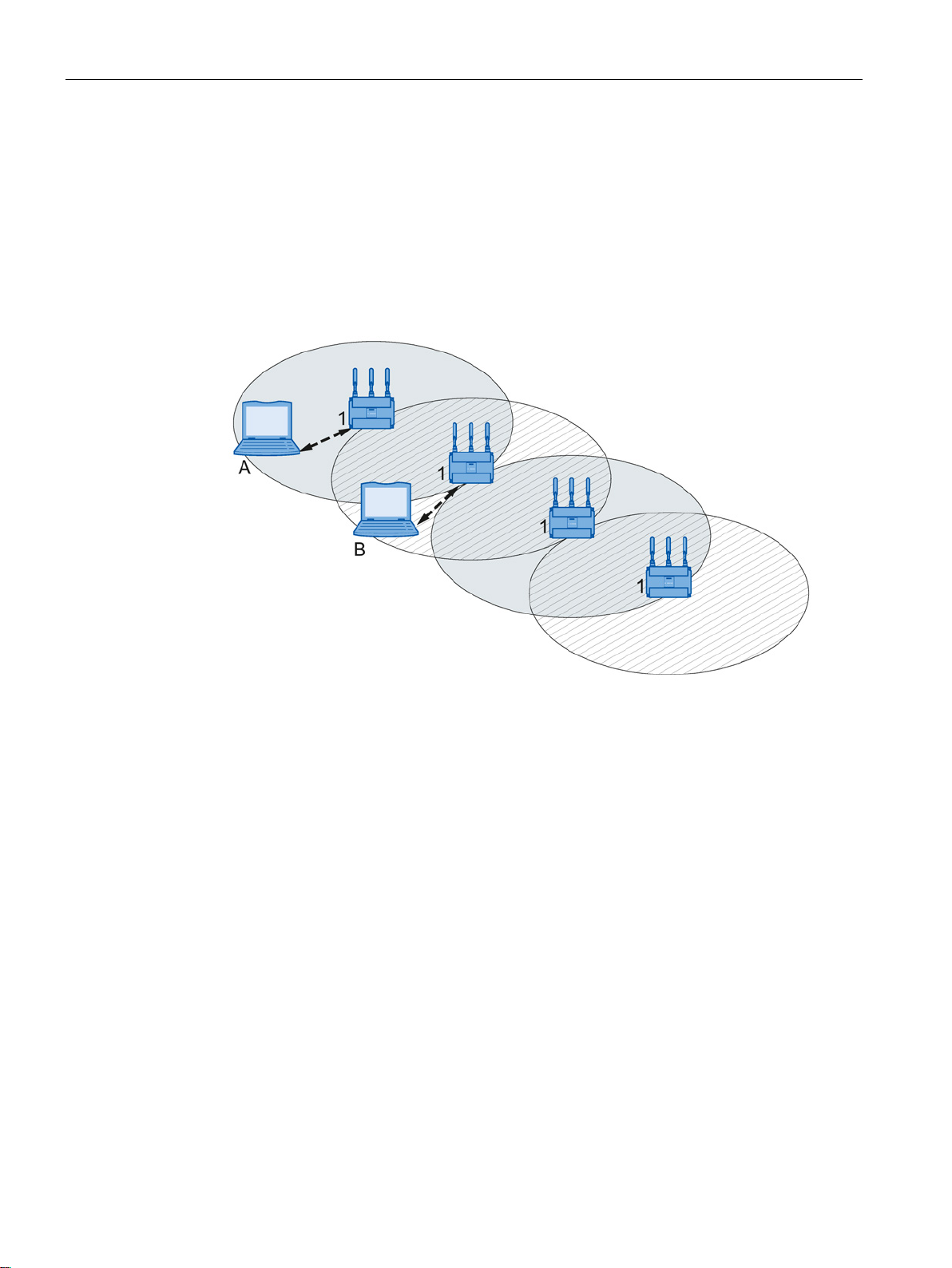
Wireless access to a wired Ethernet network
2.1 Network structures
If one (or more) access points have access to wired Ethernet, the following applications are
possible:
● A single device as gateway:
A wireless network can be connected to a wired network via an access point.
● Span of wireless coverage for the wireless network with several access points:
The access points are all configured with the same unique SSID (network name). All
nodes that want to communicate over this network must also be configured with this
SSID.
If a mobile station moves from the area covered by one access point to the area covered
by another access point, the wireless link is maintained (roaming).
Figure 2-2 Wireless connection of a mobile station over two cells (roaming)
SCALANCE W760/W720 to IEEE 802.11n Web Based Management
12 Configuration Manual, 11/2014, C79000-G8976-C350-03
Description
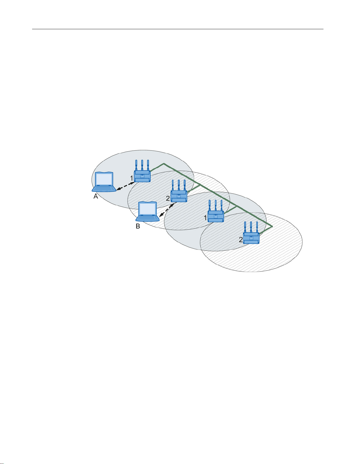
Multichannel configuration
2.1 Network structures
If neighboring access points use the same frequency channel, this can lead to longer
response times due to any collisions that may occur. If the configuration shown in the figure
is implemented as a single-channel system, computers A and B cannot communicate at the
same time with the access points in their wireless cells.
If neighboring access points are set up for different frequencies, this leads to a considerable
improvement in performance. As a result, neighboring wireless cells each have their own
medium available and the delays resulting from time-offset transmission no longer occur.
The channel spacing should be as large as possible; a practical value is 25 MHz. Even in a
multichannel configuration, all access points can be configured with the same network name.
Figure 2-3 Multichannel configuration on channels 1 and 2 with four access points
SCALANCE W760/W720 to IEEE 802.11n Web Based Management
Configuration Manual, 11/2014, C79000-G8976-C350-03
13
Description
Wireless Distribution System (WDS)
2.1 Network structures
WDS allows direct links between access points and or between access points and other
WDS-compliant devices. These are used to create a wireless backbone or to connect an
individual access point to a network that cannot be connected directly to the cable
infrastructure due to its location.
Two alternative configurations are possible. The WDS partner can be configured using the
WDS ID or using its MAC address.
Figure 2-4 Implementation of WDS with four access points
SCALANCE W760/W720 to IEEE 802.11n Web Based Management
14 Configuration Manual, 11/2014, C79000-G8976-C350-03
Description
Network access with a client or an access point in client mode
2.2
Possible applications of SCALANCE W700 devices
Note
The SIMATIC NET WLAN products use OpenSSL.
This is open source code with license conditions
Please refer to the current license conditions.
Since the driver includes encryption software, you should also adhere to the appropriate
regulations for your specific country.
Possible applications of the SCALANCE W761
2.2 Possible applications of SCALANCE W700 devices
The device can be used to integrate wired Ethernet devices (for example SIMATIC S7 PLC)
in a wireless network.
Figure 2-5 Connecting a SIMATIC S7 PLC to a wireless LAN.
The SCALANCE W761 is equipped with an Ethernet interface and a WLAN interface. This
makes the device suitable for the following applications:
(BSD).
● The SCALANCE W761 forwards data within its transmission range from one node to
another without a connection to wired Ethernet being necessary.
● The SCALANCE W761 can be used as a gateway from a wired to a wireless network.
● The SCALANCE W761 supports protection class IP20.
SCALANCE W760/W720 to IEEE 802.11n Web Based Management
Configuration Manual, 11/2014, C79000-G8976-C350-03
15

Description
Possible applications of the SCALANCE W722
Possible applications of the SCALANCE W721
2.3
Product characteristics
Properties of the SCALANCE W700 devices
2.3 Product characteristics
The SCALANCE W722 is equipped with an Ethernet interface and a WLAN interface. This
makes the device suitable for the following applications:
● The SCALANCE W722 can be used as a gateway from a wired to a wireless network.
● The SCALANCE W722 can be used with iPCF as a client.
● The SCALANCE W722 supports protection class IP20.
The SCALANCE W721 is equipped with two Ethernet interfaces and a WLAN interface. This
makes the device suitable for the following applications:
● The SCALANCE W721 can be used as a gateway from a wired to a wireless network.
● The SCALANCE W721 supports protection class IP20.
● The Ethernet interface supports the following:
– 10 Mbps and 100 Mbps both in full and half duplex
– Autocrossing
– Autopolarity
● Operating the WLAN interface in the frequency bands 2.4 GHz and 5 GHz.
● The WLAN interface is compatible with the standards IEEE 802.11a , IEEE 802.11b , and
IEEE 802.11g. In the 802.11a and 802.11g mode, the gross transmission rate is up to 54
Mbps.
● IEEE 802.11n
High-speed WLAN standard (wireless LAN) and can operate in the 2.4 GHz and in the 5
GHz range.
● IEEE 802.11h - Supplement to IEEE 802.11a
In the 802.11h mode, the methods "Transmit Power Control (TPC)" as well as "Dynamic
Frequency Selection (DFS)" are used in the range 5.25 - 5.35 and 5.47 - 5.75 GHz. In
some countries, this allows the frequency subband of 5.47 - 5.725 GHz to be used in the
outdoor area even with higher transmit powers.
TPC is a method of adapting the transmit power.
With DFS, the access point searches for primary users for 60 seconds before starting
communication on the selected channel. During this time the access point does not send
beacons. If signals are found on the channel, the channel is blocked for 30 minutes, the
access point changes channel and repeats the check. Primary users are also searched
for during operation.
SCALANCE W760/W720 to IEEE 802.11n Web Based Management
16 Configuration Manual, 11/2014, C79000-G8976-C350-03

Description
Note
The transmission standard IEEE 802.11n
supports only WPA2/WPA2
IWLAN channel
IEEE 802.11 b/g/n
WHART channel
IEEE 802.15.4
6
15 - 20
7
16 - 21
11
20 - 25
13
21 - 25
Note
All SCALANCE W700 access points can be reconfigured for client mode.
2.3 Product characteristics
● Support of the authentication standards WPA, WPA-PSK, WPA2, WPA2-PSK and
IEEE 802.1x and the encryption methods WEP, AES and TKIP.
with the setting "802.11n" or "802.11n only"
-PSK with AES in the security settings.
● For better transmission via WLAN, the function WMM (wireless multimedia) is enabled.
The frames are evaluated according to their priority and sent prioritized via the WLAN
interface.
● Suitable for inclusion of a RADIUS server for authentication.
● Device-related and application-related monitoring of the wireless connection.
● The interoperability of the devices with Wi-Fi devices of other vendors was tested
thoroughly.
● Before commissioning the SCALANCE W700, check the wireless conditions on site. If
you intend to use Industrial Wireless LAN systems and WirelessHART systems in the 2.4
GHz band, you will need to plan the use of the channels. At all costs, avoid parallel use of
overlapping frequency ranges. The following overlaps exist with Industrial Wireless LAN
and WirelessHART:
1 11 - 16
SCALANCE W760/W720 to IEEE 802.11n Web Based Management
Configuration Manual, 11/2014, C79000-G8976-C350-03
17

Description
Features of the SCALANCE W700
Type
Number of
WLAN
ports
Antennas
Number and
type of Ethernet
interface
Degree of
protection
Order no.
per)
per)
2.4
IEEE 802.11n
Overview
2.4 IEEE 802.11n
SCALANCE W761-1 RJ-45 1 external 1 x 10/100 Mbps
Ethernet (copper)
SCALANCE W722-1 RJ-45 1 external 1 x 10/100 Mbps
Ethernet (cop-
SCALANCE W721-1 RJ-45 1 external 1 x 10/100 Mbps
Ethernet (cop-
(1) US variant
The standard IEEE 802.11n is an expansion of the 802.11 standard and was approved in
2009.
Previous standards worked either in the 2.4 GHz frequency band (IEEE 802.11g /b) or in the
5 GHz frequency band (IEEE 802.11a). IEEE 802.11n can operate in both frequency band.
In the IEEE 802.11n standard, there are mechanisms implemented in PHY and MAC layers
that increase the data throughput and improve the wireless coverage.
IP20 6GK5761-1FC00-0AA0
6GK5761-1FC00-0AB0
IP20 6GK5722-1FC00-0AA0
6GK5722-1FC00-0AB0
IP20 6GK5721-1FC00-0AA0
6GK5721-1FC00-0AB0
(1)
(1)
(1)
SCALANCE W760/W720 to IEEE 802.11n Web Based Management
18 Configuration Manual, 11/2014, C79000-G8976-C350-03
● MIMO antenna technology
● Maximum ratio combining (MRC)
● Spatial multiplexing
● Channel bonding
● Frame aggregation
● Accelerated guard interval
● Modulation and coding scheme
● Data throughput rates up to 450 Mbps (gross)
This is not possible on all devices.
Description
MIMO antenna technology
Maximum ratio combining (MRC)
Spatial mutliplexing
2.4 IEEE 802.11n
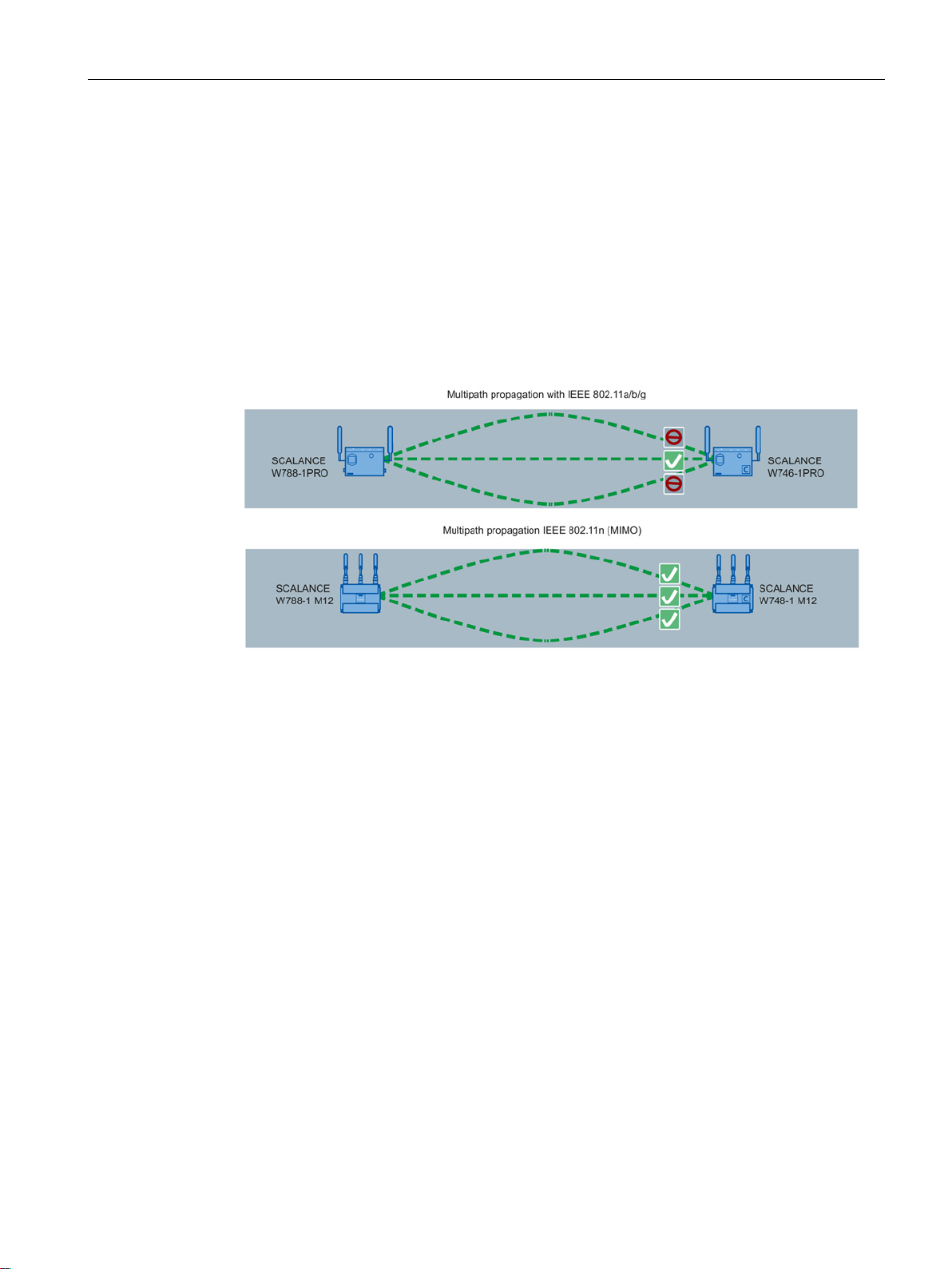
MIMO (Multiple Input - Multiple Output) is based on an intelligent multiple antenna system.
The transmitter and the receiver have several spatially separate antennas. The spatially
separate antennas transmit the data streams at the same time. Up to four data streams are
possible. The data streams are transmitted over spatially separate paths and return over
different paths due to diffraction, refraction, fading and reflection (multipath propagation).
The multipath propagation means that at the point of reception a complex, space- and timedependent pattern results as a total signal made up of the individual signals sent. MIMO
uses this unique pattern by detecting the spatial position of characteristic signals. Here, each
spatial position is different from the neighboring position. By characterizing the individual
senders, the recipient is capable of separating several signals from each other.
In a multiple antenna system, the wireless signals are received by the individual antennas
and combined to form one signal. The MRC method is used to combine the wireless signals.
The MRC method weights the wireless signals according to their signal-to-noise ratio and
combines the wireless signals to form one signal. The signal-to-noise ratio is improved and
the error rate is reduced.
With spatial multiplexing, different information is sent using the same frequency. The data
stream is distributed over n transmitting antennas; in other words, each antenna sends only
1/n of the data stream. The division of the data stream is restricted by the number of
antennas. At the receiver end, the signal is reconstructed.
Due to the spatial multiplexing, there is a higher signal-to-noise ratio and a higher data
throughput.
SCALANCE W760/W720 to IEEE 802.11n Web Based Management
Configuration Manual, 11/2014, C79000-G8976-C350-03
19
Description
Channel bonding
Frame aggregation
Accelerated guard interval
2.4 IEEE 802.11n
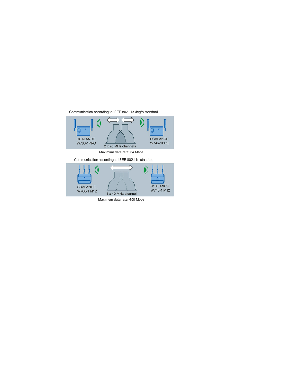
With IEEE 802.11n, data can be transferred via two directly neighboring channels. The two
20 MHz channels are put together to form one channel with 40 MHz. This allows the channel
bandwidth to be doubled and the data throughput to be increased.
To be able to use channel bonding, the recipient must support 40 MHz transmissions. If the
recipient does not support 40 MHz transmissions, the band is automatically reduced to 20
MHz. This means that IEEE 802.11n can also communicate with IEEE 802.11a/b/g devices.
The channel bonding is set on the "AP" WBM page with the "HT Channel Width [MHz]"
parameter.
With IEEE 802.11n, it is possible to group together individual data packets to form a single
larger packet; this is known as frame aggregation. There are two types of frame aggregation:
Aggregated MAC Protocol Data Unit (A-MPDU) and Aggregated MAC Service Data Unit (AMSDU).
The frame aggregation reduces the packet overheads. Frame aggregation can only be used
if the individual data packets are intended for the same receiving station (client).
The W700 devices support both types of frame aggregation. You specify the settings for the
A-MPDU data packet on the "AP 802.11n" WBM page.
The guard interval prevents different transmissions being mixed together. In
telecommunications, this mixing is also known as intersymbol interference (ISI).
When the send time has elapsed, a send pause (guard interval) must be kept to before the
next transmission begins.
The guard interval of IEEE 802.11a /b/g is 800 ns. IEEE 802.11n can use the reduced guard
interval of 400 ns. You specify the guard interval on the "AP 802.11n" WBM page.
SCALANCE W760/W720 to IEEE 802.11n Web Based Management
20 Configuration Manual, 11/2014, C79000-G8976-C350-03

Description
Modulation and coding schemes
2.5
Requirements for installation and operation
Requirements for installation and operation of SCALANCE W700 devices
2.5 Requirements for installation and operation
The IEEE 802.11n standard supports different data rates. The data rates are based on the
number of spatial streams, the modulation method and the channel coding. The various
combinations are described in modulation and coding schemes.
A PG/PC with a network connection must be available in order to configure
SCALANCE W700 devices. If no DHCP server is available, a PC on which the Primary
Setup Tool (PST) is installed is necessary for the initial assignment of an IP address to the
SCALANCE W700 devices. For the other configuration settings, a computer with Telnet or a
Web browser is necessary.
SCALANCE W760/W720 to IEEE 802.11n Web Based Management
Configuration Manual, 11/2014, C79000-G8976-C350-03
21

Description
2.5 Requirements for installation and operation
SCALANCE W760/W720 to IEEE 802.11n Web Based Management
22 Configuration Manual, 11/2014, C79000-G8976-C350-03

3
3.1
VLAN
Network definition regardless of the spatial location of the nodes
Options for the VLAN assignment
3.2
MAC-based communication
Adopt MAC automatically / Adopt MAC manually
VLAN (Virtual Local Area Network) divides a physical network into several logical networks
that are shielded from each other. Here, devices are grouped together to form logical groups.
Only nodes of the same VLAN can address each other. Since multicast and broadcast
frames are only forwarded within the particular VLAN, they are also known as broadcast
domains.
The particular advantage of VLANs is the reduced network load for the nodes and network
segments of other VLANs.
To identify which packet belongs to which VLAN, the frame is expanded by 4 bytes. This
expansion includes not only the VLAN ID but also priority information.
There are various options for the assignment to VLANs:
● Port-based VLAN
Each port of a device is assigned a VLAN ID. You configure port-based VLAN in "Layer 2
> VLAN (Page 200)".
● Protocol-based VLAN
Each port of a device is assigned a protocol group.
● Subnet-based VLAN
The IP address of the device is assigned a VLAN ID.
Frames in the direction from the client to the access point always have the MAC address of
the WLAN interface as the source MAC address. As a result, the "learning table" at the
access point end always has only the MAC address of the WLAN interface of the client. If the
MAC address of a device connected to the client is adopted, both the MAC-based and the
IP-based frames find their destination in precisely this device.
Communication at the MAC address level (ISO/OSI layer 2) can only be to a subscriber
downstream from the client. With IP Mapping, several subscribers downstream from a client
can be addressed based on the IP protocol.
SCALANCE W760/W720 to IEEE 802.11n Web Based Management
Configuration Manual, 11/2014, C79000-G8976-C350-03
23

Technical basics
Note
From the moment that the device adopts another MAC address (whether
automatically), the device no longer responds to queries of the Primary Setup Tool when
the query is received over the WLAN interface. Queries of the PST over the Ethernet
interface continue to be replied to.
Adopt Own MAC
Layer 2 Tunnel
3.2 MAC-based communication
The access point checks whether the destination MAC address matches the MAC addresses
of the connected clients. Since a client can only adopt one MAC address, the access point
does not find a match and discards the packets of several nodes.
Maximum possible number of nodes downstream from the client: 1
Notes on the "Automatic" setting:
● As long as there is no link on the Ethernet interface, the device uses the MAC address of
the Ethernet interface so that it can be reached in this status. In this status, the device
can be found using the Primary Setup Tool and configured with WBM or CLI.
● As soon as there is a link on the Ethernet interface, the device adopts the source MAC
address of the first received frame.
manually or
If IP-based frames need to be sent to a device connected downstream from the client, the
default setting "Own" can be retained. The client registers with the MAC address of its
Ethernet adapter. The IP packets are broken down according to an internal table and
forwarded to the connected devices (IP mapping).
Maximum possible number of nodes downstream from the client: 4
With a "Layer 2 Tunnel", the client provides information about the devices downstream from
it when it registers with an access point. This makes it possible to enter the MAC addresses
of these devices in the learning table of the access point. The access point can forward
MAC-based frames for the devices downstream from the client to the appropriate client.
In much the same way as with WDS, a separate port is created for the L2T client over which
the Ethernet frames are sent without changing the destination MAC address.
Maximum possible number of nodes downstream from the client: 4
SCALANCE W760/W720 to IEEE 802.11n Web Based Management
24 Configuration Manual, 11/2014, C79000-G8976-C350-03

Technical basics
3.3
iPCF / iPCF-MC
iPCF
iPCF-MC
iPCF / iPCF-MC - how it works
3.3 iPCF / iPCF-MC
The wireless range of an IWLAN system can be expanded by using multiple access points. If
a client moves from the area covered by one access point to the area covered by another
access point, the wireless link is maintained after a short interruption (roaming).
In an industrial environment, there are applications that require a deterministic response
when there are large numbers of nodes and when roaming to another cell require handover
times of less than 100 milliseconds.
●
(industrial Point Coordination Function)
iPCF ensures that the entire data traffic of a cell is ordered, controlled by the access
point. Even with large numbers of nodes, collisions can also be avoided. iPCF also allows
fast cell changes.
You configure iPCF in "iFeatures > iPCF (Page 232)".
●
iPCF-MC was developed to make the advantages of iPCF available to fully mobile nodes
that communicate without being dependent on RCoax cable or directional antennas. With
iPCF-MC, the client also searches for potentially suitable access points when it receives
iPCF queries from the access point and the existing connection to an access point is
working problem-free. This means that if a change to a different access point is
necessary, this is achieved extremely quickly. In contrast to iPCF, the handover times for
iPCF-MC are not dependent on the number of wireless channels being used.
(industrial Point Coordination Function - Management Channel)
You configure iPCF-MC in "iFeatures > iPCF-MC (Page 232)".
The access point checks all nodes in the wireless cell cyclically. At the same time, the scan
includes the downlink traffic for this node. In the reply, the node sends the uplink data. The
access point scans a new node at least every 5 ms.
The scan of a node is seen by all other nodes in the cell. This allows a client to detect the
quality of the wireless link to the access point even when it is not communicating with the
access point itself. If the client does not receive any frames from the access point for a
certain time, it starts to search for a new access point.
In iPCF mode, both the search for a new access point and the registration with this access
point have been optimized in terms of time. Handover times significantly below 50 ms are
achieved.
Stable PNIO communication is only possible when a WLAN client is in a cell with more than
60 % (-65 dBm) signal strength at all times. This can be checked by activating and
deactivating the various wireless cells.
This does not mean that the client needs to change when there is a signal strength < 60 %
(< -65 dBm). Make sure that access points are available with adequate signal strength.
SCALANCE W760/W720 to IEEE 802.11n Web Based Management
Configuration Manual, 11/2014, C79000-G8976-C350-03
25

Technical basics
①
Wireless cell of access point 1
②
Wireless cell of access point 2
③
Wireless cell of access point 3
④
Wireless cell of access point 4
⑤
Plant
3.3 iPCF / iPCF-MC
SCALANCE W760/W720 to IEEE 802.11n Web Based Management
26 Configuration Manual, 11/2014, C79000-G8976-C350-03
Figure 3-1 Configuration example of iPCF-MC

Technical basics
Restrictions
Requirements for iPCF-MC
See also
3.4
NAT/NAPT
Layer 3 possible only with SCALANCE W722-1 RJ-45
What is NAT?
3.4 NAT/NAPT
● iPCF and iPCF-MC are developments of Siemens AG and function only with nodes on
which iPCF / iPCF-MC is implemented.
● With an access point with several WLAN interfaces, it is possible to use both iPCF as well
as standard WLAN at the same time.
● Access points with a WLAN interface cannot take part in the iPCF-MC procedures, iPCF
is, however, possible.
iPCF-MC uses the two wireless interface of the access point in different ways: One interface
works as the management interface and sends a beacon every five milliseconds. The other
interface transfers the user data.
The following requirements must be met before you can use iPCF-MC:
● Only devices with two WLAN interfaces can be used as access points
● The data interface (WLAN1) and management interface (WLAN2) must be operated in
the same frequency band and must match in terms of their wireless coverage. iPCF-MC
will not work if the two wireless interfaces are equipped with directional antennas that
cover different areas.
● The management interfaces of all access points to which a client can change must use
the same channel. A client scans only this one channel to find accessible access points.
● Transmission based on IEEE 802.11h (DFS) cannot be used for the management
interface. 802.11h (DFS) is possible for the data interface.
● A client must support this feature on its WLAN interface.
iPCF-MC (Page 233)
The use of the layer 3 functions is possible only with the client SCALANCE W722-1 RJ-45.
With Network Address Translation (NAT), the IP address in a data packet is replaced by
another. NAT is normally used on a gateway between a private LAN and an external network
with globally valid IP addresses. A local IP address of the internal LAN is changed to an
external global IP address by a NAT device at the gateway.
SCALANCE W760/W720 to IEEE 802.11n Web Based Management
Configuration Manual, 11/2014, C79000-G8976-C350-03
27

Technical basics
What is NAPT?
Note
NAT/NAPT is possible only on layer 3 of the ISO/OSI reference model. To use the NAT
function, the networks must use the IP protocol.
When using the ISO protocol that operates at layer 2, it is not possible to use NAT.
3.5
SNMP
Introduction
3.5 SNMP
To translate the internal into the global IP address, the NAT device maintains a translation
list. The address assignment is automatic. You configure the address assignment in "Layer 3
> NAT > Basic".
In "Network Address Port Translation" (NAPT) or "Port Address Translation" (PAT), several
internal source IP addresses are translated into the same external source IP address. To
identify the individual source nodes, the port of the source device is also stored in the
translation list of the NAT gateway and translated for the external address.
If several local clients send a query to the same external destination IP address over the
NAT gateway, the gateway enters its own external source IP address in the header of these
forwarded frames. Since the forwarded frames have the same global source IP address, the
NAT gateway assigns the frames to the clients using different port number.
If a client from the global network wants to use a service in the internal network, the
translation list for the static address assignment needs to be configured. You configure the
translation list for NAPT in "Layer 3 > NAT > NAPT".
With the aid of the Simple Network Management Protocol (SNMP), you monitor and control
network elements from a central station, for example routers or switches. SNMP controls the
communication between the monitored devices and the monitoring station.
Tasks of SNMP:
● Monitoring of network components
● Remote control and remote parameter assignment of network components
● Error detection and error notification
In versions v1 and v2c, SNMP has no security mechanisms. Each user in the network can
access data and also change parameter assignments using suitable software.
For the simple control of access rights without security aspects, community strings are used.
The community string is transferred along with the query. If the community string is correct,
the SNMP agent responds and sends the requested data. If the community string is not
correct, the SNMP agent discards the query. Define different community strings for read and
write permissions. The community strings are transferred in plain text.
SCALANCE W760/W720 to IEEE 802.11n Web Based Management
28 Configuration Manual, 11/2014, C79000-G8976-C350-03

Technical basics
Note
Because the SNMP community strings are used f
standard values "public" or "private". Change these values following the initial
commissioning.
3.5 SNMP
Standard values of the community strings:
● public
has only read permissions
● private
has read and write permissions
or access protection, do not use the
Further simple protection mechanisms at the device level:
● Allowed Host
The IP addresses of the monitoring systems are known to the monitored system.
● Read Only
If you assign "Read Only" to a monitored device, monitoring stations can only read out
data but cannot modify it.
SNMP data packets are not encrypted and can easily be read by others.
The central station is also known as the management station. An SNMP agent is installed on
the devices to be monitored with which the management station exchanges data.
The management station sends data packets of the following type:
● GET
Request for a data record from the agent
● GETNEXT
Calls up the next data record.
● GETBULK (available as of SNMPv2)
Requests multiple data records at one time, for example several rows of a table.
● SET
Contains parameter assignment data for the relevant device.
The SNMP agent sends data packets of the following type:
● RESPONSE
The agent returns the data requested by the manager.
● TRAP
If a certain event occurs, the SNMP agent itself sends traps.
SNMPv1 and SNMPv2 and SNMPv3 use UDP (User Datagram Protocol). The data is
described in a Management Information Base (MIB).
SCALANCE W760/W720 to IEEE 802.11n Web Based Management
Configuration Manual, 11/2014, C79000-G8976-C350-03
29

Technical basics
SNMPv3
3.6
Spanning Tree
Avoiding loops
Root bridge and bridge priority
Response to changes in the network topology
Keeping configuration information up to date
3.6 Spanning Tree
Compared with the previous versions SNMPv1 and SNMPv2. SNMPv3 introduces an
extensive security concept.
SNMPv3 supports:
● Fully encrypted user authentication
● Encryption of the entire data traffic
● Access control of the MIB objects at the user/group level
The Spanning Tree algorithm detects redundant physical network structures and prevents
the formation of loops by disabling redundant paths. It evaluates the distance and
performance of a connection or bases the decisions on settings made by the user. Data is
then exchanged only over the remaining connection paths.
If the preferred data path fails, the Spanning Tree algorithm then searches for the most
efficient path possible with the remaining nodes.
The identification of the most efficient connection is always related to the root bridge, a
network component that can be considered as a root element of a tree-like network
structure. With the "Bridge Priority" parameter, you can influence the selection of the root
bridge. The computer with the lowest value set for this parameter automatically becomes the
root bridge. If two computers have the same priority value, the computer with the lower MAC
address becomes the root bridge.
If nodes are added to a network or drop out of the network, this may affect the optimum path
selection for data packets. To be able to respond to such changes, the root bridge sends
configuration messages (BPDUs) at regular intervals. You can set the interval between two
configuration messages with the "Hello Time" parameter.
With the "Max Age" parameter, you set the maximum age of configuration information. If a
bridge has information that is older than the time set in Max Age, it discards the message
and initiates recalculation of the paths.
New configuration data is not used immediately by a bridge but only after the period
specified in the "Forward Delay" parameter. This ensures that operation is started with the
new topology only after all the bridges have the required information.
SCALANCE W760/W720 to IEEE 802.11n Web Based Management
30 Configuration Manual, 11/2014, C79000-G8976-C350-03
 Loading...