

SCALANCE S615
___________________
___________________
___________________
___________________
___________________
___________________
SIMATIC NET
Industrial Ethernet Security
SCALANCE S615
Web Based Management
Configuration Manual
05/2015
C79000
Preface
Description
1
Technical basics
2
Security recommendation
3
Configuring with Web Based
Management
4
Service and maintenance
5
-G8976-C388-02

Siemens AG
Division Process Industries and Drives
Postfach 48 48
90026 NÜRNBERG
GERMANY
C79000-G8976-C388-01
Ⓟ
Copyright © Siemens AG 2015.
All rights reserved
Legal information
Warning notice system
DANGER
indicates that death or severe personal injury will result if proper precautions are not taken.
WARNING
indicates that death or severe personal injury may result if proper precautions are not taken.
CAUTION
indicates that minor personal injury can result if proper precautions are not taken.
NOTICE
indicates that property damage can result if proper precautions are not taken.
Qualified Personnel
personnel qualified
Proper use of Siemens products
WARNING
Siemens products may only be used for the applications described in the catalog and in the relevant technical
ambient conditions must be complied with. The information in the relevant documentation must be observed.
Trademarks
Disclaimer of Liability
This manual contains notices you have to observe in order to ensure your personal safety, as well as to prevent
damage to property. The notices referring to your personal safety are highlighted in the manual by a safety alert
symbol, notices referring only to property damage have no safety alert symbol. These notices shown below are
graded according to the degree of danger.
If more than one degree of danger is present, the warning notice representing the highest degree of danger will
be used. A notice warning of injury to persons with a safety alert symbol may also include a warning relating to
property damage.
The product/system described in this documentation may be operated only by
task in accordance with the relevant documentation, in particular its warning notices and safety instructions.
Qualified personnel are those who, based on their training and experience, are capable of identifying risks and
avoiding potential hazards when working with these products/systems.
Note the following:
documentation. If products and components from other manufacturers are used, these must be recommended
or approved by Siemens. Proper transport, storage, installation, assembly, commissioning, operation and
maintenance are required to ensure that the products operate safely and without any problems. The permissible
All names identified by ® are registered trademarks of Siemens AG. The remaining trademarks in this publication
may be trademarks whose use by third parties for their own purposes could violate the rights of the owner.
We have reviewed the contents of this publication to ensure consistency with the hardware and software
described. Since variance cannot be precluded entirely, we cannot guarantee full consistency. However, the
information in this publication is reviewed regularly and any necessary corrections are included in subsequent
editions.
for the specific
05/2015 Subject to change

Preface
Validity of the manual
Purpose of the Configuration Manual
Orientation in the documentation
This Configuration Manual covers the following product:
● SCALANCE S615
This Configuration Manual applies to the following software version:
● SCALANCE S615 firmware as of Version V04.00
This Configuration Manual is intended to provide you with the information you require to
install, commission and operate the device. It provides you with the information you require
to configure the devices.
Apart from the Configuration Manual you are currently reading, the following documentation
is also available from on the topic of Remote Network:
● Getting Started SCALANCE S615
Based on examples, this document explains the configuration of the SCALANCE S615.
● Operating Instructions SCALANCE S615
You will find this document on the Internet pages of Siemens Industry Online Support. It
contains information on installation, connecting up and approvals of the SCALANCE
S615.
● Operating Instructions SINEMA RC Server
You will find this document on the Internet pages of Siemens Industry Online Support. It
contains information on the installation, configuration and operation of the application
SINEMA Remote Connect Server.
SCALANCE S615 Web Based Management
Configuration Manual, 05/2015, C79000-G8976-C388-02
3

Preface
SIMATIC NET manuals
SIMATIC NET glossary
Security information
You will find SIMATIC NET manuals on the Internet pages of Siemens Industry Online
Support:
● Using the search function:
Link to Siemens Industry Online Support
(http://support.automation.siemens.com/WW/view/en)
Enter the entry ID of the relevant manual as the search item.
● In the navigation panel on the left-hand side in the area "Industrial Communication":
Link to the area "Industrial Communication"
(http://support.automation.siemens.com/WW/view/en/10805878/130000)
Go to the required product group and make the following settings:
tab "Entry list", Entry type "Manuals"
You will find the documentation for the SIMATIC NET products relevant here on the data
storage medium that ships with some products:
● Product CD / product DVD
● SIMATIC NET Manual Collection
Explanations of many of the specialist terms used in this documentation can be found in the
SIMATIC NET glossary.
You will find the SIMATIC NET glossary here:
● SIMATIC NET Manual Collection or product DVD
The DVD ships with certain SIMATIC NET products.
● On the Internet under the following entry ID:
50305045 (http://support.automation.siemens.com/WW/view/en/50305045)
Siemens provides products and solutions with industrial security functions that support the
secure operation of plants, solutions, machines, equipment and/or networks. They are
important components in a holistic industrial security concept. With this in mind, Siemens’
products and solutions undergo continuous development. Siemens recommends strongly
that you regularly check for product updates.
For the secure operation of Siemens products and solutions, it is necessary to take suitable
preventive action (e.g. cell protection concept) and integrate each component into a holistic,
state-of-the-art industrial security concept. Third-party products that may be in use should
also be considered. For more information about industrial security, visit
http://www.siemens.com/industrialsecurity.
To stay informed about product updates as they occur, sign up for a product-specific
newsletter. For more information, visit http://support.automation.siemens.com.
SCALANCE S615 Web Based Management
4 Configuration Manual, 05/2015, C79000-G8976-C388-02

Preface
Firmware
License conditions
Note
Open source software
Read the license conditions for open source software carefully before using the product.
The firmware is signed and encrypted. This ensures that only firmware created by Siemens
can be downloaded to the device.
You will find license conditions in the following documents on the supplied data medium:
● DOC_OSS-SCALANCE-M_74.pdf
● DC_LicenseSummaryScalanceS615_76.htm
SCALANCE S615 Web Based Management
Configuration Manual, 05/2015, C79000-G8976-C388-02
5

Preface
Trademarks
The following and possibly other names not identified by the registered trademark sign ® are
registered trademarks of Siemens AG:
SCALANCE
SCALANCE S615 Web Based Management
6 Configuration Manual, 05/2015, C79000-G8976-C388-02

Table of contents
Preface ................................................................................................................................................... 3
1 Description ............................................................................................................................................ 11
2 Technical basics ................................................................................................................................... 19
3 Security recommendation ...................................................................................................................... 33
4 Configuring with Web Based Management ............................................................................................ 37
1.1 Function .................................................................................................................................. 11
1.2 Requirements for operation .................................................................................................... 13
1.3 Configuration examples .......................................................................................................... 14
1.3.1 TeleControl with SINEMA RC ................................................................................................. 14
1.3.2 Secure access with S615 ....................................................................................................... 16
1.4 Digital input / output ................................................................................................................ 17
2.1 IPv4 address, subnet mask and address of the gateway ....................................................... 19
2.2 VLAN ....................................................................................................................................... 21
2.2.1 VLAN ....................................................................................................................................... 21
2.2.2 VLAN tagging .......................................................................................................................... 22
2.3 NAT ......................................................................................................................................... 24
2.4 SNMP ...................................................................................................................................... 26
2.5 Security functions .................................................................................................................... 28
2.5.1 Firewall .................................................................................................................................... 28
2.5.2 IPsecVPN ................................................................................................................................ 29
2.5.3 Certificates .............................................................................................................................. 32
4.1 Web Based Management ....................................................................................................... 37
4.2 Starting and logging in ............................................................................................................ 39
4.3 "Information" menu ................................................................................................................. 42
4.3.1 Start page ............................................................................................................................... 42
4.3.2 Versions .................................................................................................................................. 47
4.3.3 ARP Table ............................................................................................................................... 48
4.3.4 Log tables ............................................................................................................................... 49
4.3.4.1 Event log ................................................................................................................................. 49
4.3.4.2 Security log ............................................................................................................................. 51
4.3.4.3 Firewall log .............................................................................................................................. 53
4.3.5 Faults ...................................................................................................................................... 55
4.3.6 DHCP Server .......................................................................................................................... 56
4.3.7 LLDP ....................................................................................................................................... 57
4.3.8 Routing table ........................................................................................................................... 58
4.3.9 IPsec VPN ............................................................................................................................... 59
4.3.10 SINEMA RC ............................................................................................................................ 60
4.4 "System" menu ....................................................................................................................... 62
SCALANCE S615 Web Based Management
Configuration Manual, 05/2015, C79000-G8976-C388-02
7

Table of contents
4.4.1 Configuration .......................................................................................................................... 62
4.4.2 General .................................................................................................................................. 65
4.4.2.1 Device .................................................................................................................................... 65
4.4.2.2 Coordinates ............................................................................................................................ 67
4.4.3 Restart .................................................................................................................................... 68
4.4.4 Load and Save ....................................................................................................................... 70
4.4.4.1 HTTP ...................................................................................................................................... 70
4.4.4.2 TFTP ...................................................................................................................................... 73
4.4.4.3 Passwords .............................................................................................................................. 75
4.4.5 Events .................................................................................................................................... 76
4.4.5.1 Configuration .......................................................................................................................... 76
4.4.5.2 Severity filter .......................................................................................................................... 78
4.4.6 SMTP client ............................................................................................................................ 80
4.4.7 SNMP ..................................................................................................................................... 82
4.4.7.1 General .................................................................................................................................. 82
4.4.7.2 Traps ...................................................................................................................................... 83
4.4.7.3 Groups ................................................................................................................................... 85
4.4.7.4 Users ...................................................................................................................................... 87
4.4.8 System Time .......................................................................................................................... 89
4.4.8.1 Manual setting ........................................................................................................................ 89
4.4.8.2 SNTP client ............................................................................................................................ 91
4.4.8.3 NTP client ............................................................................................................................... 93
4.4.8.4 SIMATIC Time Client ............................................................................................................. 95
4.4.9 Auto logout ............................................................................................................................. 97
4.4.10 Syslog Client .......................................................................................................................... 98
4.4.11 Fault monitoring ..................................................................................................................... 99
4.4.12 PLUG ................................................................................................................................... 102
4.4.12.1 Configuration ........................................................................................................................ 102
4.4.12.2 License ................................................................................................................................. 105
4.4.13 Ping ...................................................................................................................................... 107
4.4.14 DNS ...................................................................................................................................... 108
4.4.14.1 DNS client ............................................................................................................................ 108
4.4.14.2 DNS proxy ............................................................................................................................ 109
4.4.14.3
DDNS client .......................................................................................................................... 110
4.4.15 DHCP ................................................................................................................................... 111
4.4.15.1 DHCP client .......................................................................................................................... 111
4.4.15.2 DHCP server ........................................................................................................................ 113
4.4.15.3 DHCP Options...................................................................................................................... 115
4.4.15.4 Static Leases ........................................................................................................................ 116
4.4.16 SRS ...................................................................................................................................... 118
4.4.17 Proxy server ......................................................................................................................... 119
4.4.18 SINEMA RC ......................................................................................................................... 121
4.5 "Interfaces" menu ................................................................................................................. 123
4.5.1 Ethernet ................................................................................................................................ 123
4.5.1.1 Overview .............................................................................................................................. 123
4.5.1.2 Configuration ........................................................................................................................ 124
4.6 "Layer 2" menu ..................................................................................................................... 127
4.6.1 Dynamic MAC Aging ............................................................................................................ 127
4.6.2 VLAN .................................................................................................................................... 128
4.6.2.1 General ................................................................................................................................ 128
4.6.2.2 Port Based VLAN ................................................................................................................. 130
SCALANCE S615 Web Based Management
8 Configuration Manual, 05/2015, C79000-G8976-C388-02

Table of contents
5 Service and maintenance .................................................................................................................... 169
Index................................................................................................................................................... 177
4.6.3 LLDP ..................................................................................................................................... 132
4.7 "Layer 3" menu ..................................................................................................................... 134
4.7.1 Routes ................................................................................................................................... 134
4.7.2 Subnets ................................................................................................................................. 135
4.7.2.1 Overview ............................................................................................................................... 135
4.7.2.2 Configuration ......................................................................................................................... 137
4.7.3 NAT ....................................................................................................................................... 138
4.7.3.1 Masquerading ....................................................................................................................... 138
4.7.3.2 NAPT..................................................................................................................................... 139
4.7.3.3 Source NAT .......................................................................................................................... 141
4.7.3.4 NETMAP ............................................................................................................................... 143
4.8 "Security" menu .................................................................................................................... 146
4.8.1 Password .............................................................................................................................. 146
4.8.2 Certificates ............................................................................................................................ 147
4.8.2.1 Overview ............................................................................................................................... 147
4.8.2.2 Certificates ............................................................................................................................ 149
4.8.3 Firewall .................................................................................................................................. 152
4.8.3.1 General ................................................................................................................................. 152
4.8.3.2 Predefined IPv4 .................................................................................................................... 153
4.8.3.3 IP Services ............................................................................................................................ 154
4.8.3.4 ICMP Services ...................................................................................................................... 156
4.8.3.5 IP Protocols ........................................................................................................................... 157
4.8.3.6 IP Rules ................................................................................................................................ 158
4.8.4 IPsec VPN ............................................................................................................................. 159
4.8.4.1 General ................................................................................................................................. 159
4.8.4.2 Remote End .......................................................................................................................... 160
4.8.4.3 Connections .......................................................................................................................... 162
4.8.4.4 Authentication ....................................................................................................................... 164
4.8.4.5 Phase 1 ................................................................................................................................. 165
4.8.4.6 Phase 2 ................................................................................................................................. 167
5.1 Firmware update using HTTP ............................................................................................... 169
5.1.1 Firmware update using HTTP ............................................................................................... 169
5.2 Firmware update - using TFTP ............................................................................................. 171
5.3 Firmware update using WBM not possible ........................................................................... 173
5.4 Firmware update using WBM not possible ........................................................................... 175
SCALANCE S615 Web Based Management
Configuration Manual, 05/2015, C79000-G8976-C388-02
9

Table of contents
SCALANCE S615 Web Based Management
10 Configuration Manual, 05/2015, C79000-G8976-C388-02

1
1.1
Function
Configuration
Security functions
Configuration of all parameters using the
● Web Based Management (WBM) via HTTP and HTTPS.
● Command Line Interface (CLI) via Telnet and SSH.
● Router with NAT function
– IP masquerading
– NAPT
– SourceNAT
– NETMAP
● Password protection
● Firewall function
– Port forwarding
– IP firewall with stateful packet inspection (layer 3 and 4)
– Global and user-defined firewall rules
● VPN functions
To establish a VPN (Virtual Private Network), the following functions are available
– IPsecVPN for up to 20 connections
● SINEMA RC client
● Proxy server
SCALANCE S615 Web Based Management
Configuration Manual, 05/2015, C79000-G8976-C388-02
11

Description
Monitoring / diagnostics / maintenance
Other functions
1.1 Function
● LEDs
Display of operating statuses via the LED display. You will find further information on this
in the Operating Instructions of the device.
● Logging
For monitoring have the events logged.
● SNMP
For monitoring and controlling network components such as routers or switches from a
central station.
● Time-of-day synchronization
– NTP
– SNTP
● DHCP
– DHCP server (local network)
– DHCP client
● Virtual networks (VLAN)
To structure Industrial Ethernet networks with a fast growing number of nodes, a physical
network can be divided into several virtual subnets
● Digital input/digital output
● Dynamic DNS client
● DNS client
● SMTP client
SCALANCE S615 Web Based Management
12 Configuration Manual, 05/2015, C79000-G8976-C388-02

Description
1.2
Requirements for operation
Power supply
Configuration
Default values set in the factory
ration
Subnet mask
255.255.255.0
"Restore Factory Defaults and Restart"
1.2 Requirements for operation
A power supply with a voltage between 12 VDC and 24 VDC that can provide sufficient
current.
You will find further information on this in the device-specific operating instructions.
In the factory settings, the SCALANCE S615 can be reached as follows for initial
configuration:
Ethernet interface for the configu-
IP address 192.168.1.1
User name admin (cannot be changed)
Password admin
P1 ... P4
The password needs to be changed after the first logon or after a
You will find more information in "Web Based Management (Page 37)" and in "Starting and
logging in (Page 39)".
SCALANCE S615 Web Based Management
Configuration Manual, 05/2015, C79000-G8976-C388-02
13
Description
1.3
Configuration examples
1.3.1
TeleControl with SINEMA RC
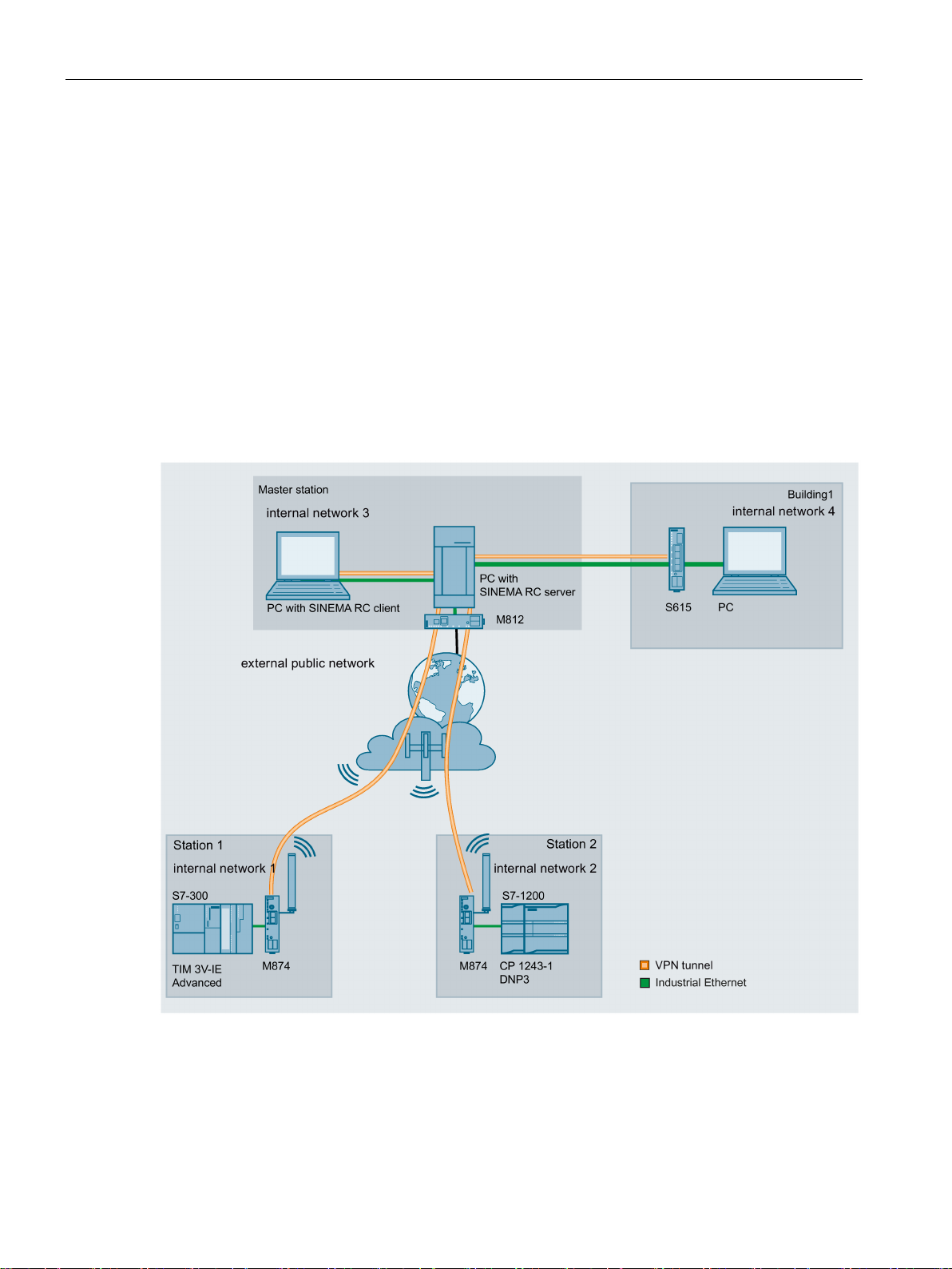
1.3 Configuration examples
In this configuration, the remote maintenance master station is a connected to the
Internet/intranet via the SINEMA Remote Connect Server. The stations communicate via
SCALANCE M874 or SCALANCE S615 that establish a VPN tunnel to the SINEMA RC
server. In the master station, the SINEMA RC client establishes a VPN tunnel to the
SINEMA RC server.
The devices must log on to the SINEMA RC server. The VPN tunnel between the device and
the SINEMA RC server is established only after successful authentication. Depending on the
configured communications relations and the security settings, the SINEMA RC server
connects the individual VPN tunnels.
SCALANCE S615 Web Based Management
14 Configuration Manual, 05/2015, C79000-G8976-C388-02

Description
Procedure
1.3 Configuration examples
To be able to access a plant via a remote maintenance master station, follow the steps
below:
1. Establish the Ethernet connection between the S615 and the connected Admin PC.
2. Create the devices and node groups on the SINEMA RC Server.
3. Configure the connection to the SINEMA RC server on the device, refer to the section
SINEMA RC (Page 121).
4. Set up the connected applications of the plant for data communication.
SCALANCE S615 Web Based Management
Configuration Manual, 05/2015, C79000-G8976-C388-02
15
Description
1.3.2
Secure access with S615
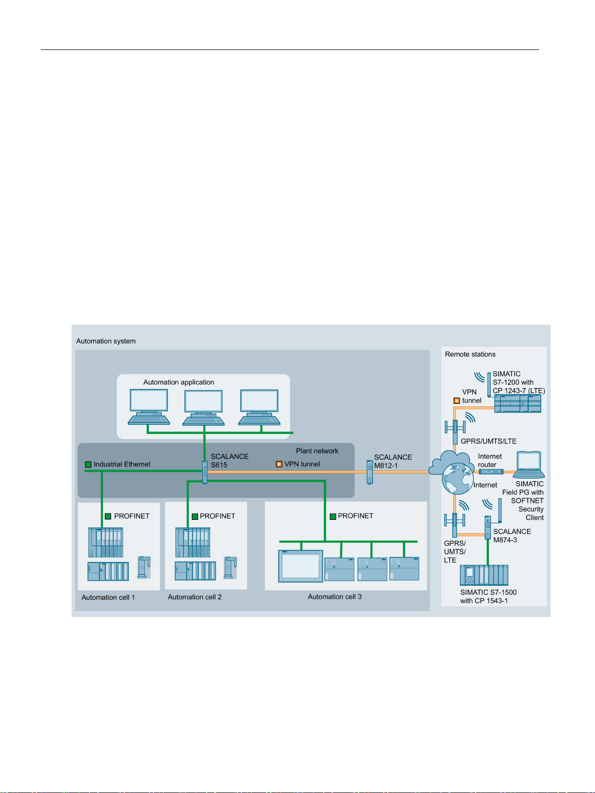
Secure remote access and network segmentation with SCALANCE S615
1.3 Configuration examples
A secure connection for data exchange between an automation plant and remote stations
will be established via the Internet and mobile wireless network. At the same time, a secure
connection will be established when necessary for service purposes. This connection is,
however, restricted to a specific plant section or a specific machine.
In the automation plant, a SCALANCE S615 is connected to the Internet via the ADSL+
router M812-1. The remote stations will be connected to the Internet via the LTE-CP 1243-7
or the HSPA+ router SCALANCE M874-3.
SCALANCE S615 via which data can be exchanged securely.
When necessary, the service technician connects to the Internet. With the SOFTNET
Security Client, he or she establishes a secure VPN connection to the S615. Various IP
subnets are connected to the S615 between which the integrated firewall checks
communication. This allows the communication of the service technician to be restricted to a
specific IP subnet.
The devices establish a VPN connection to the
SCALANCE S615 Web Based Management
16 Configuration Manual, 05/2015, C79000-G8976-C388-02

Description
1.4
Digital input / output
Introduction
Application example
Control of the digital output
Note
You can control the digital output directly via CLI or SNMP. In WBM and CLI, you can
configure the use of the digital output in "Events". Do not control the digital output direc
when you use this in the WBM and CLI.
Note
If the digital input changes the status, an entry is made in the event protocol table.
1.4 Digital input / output
The devices have a digital input/output.
The connection is made using two 2-pin terminal blocks. You will find information about the
pin assignment in the operating instructions of the devices.
● Digital input e.g. for establishing a VPN connection
● Digital output e.g. to signal existing VPN connections.
Using CLI and using the private MIB variable snMspsDigitalOutputLevel, you can control the
digital output (DO/1L).
tly
● OID of the private MIB variable snMspsDigitalOutputLevel:
iso(1).org(3).dod(6).internet(1).private(4).enterprises(1).siemens(4329).industria
lComProducts(20).iComPlatforms(1).simaticNet(1).snMsps(1).snMspsCommon(1).snMspsDi
gitalIO(39).snMspsDigitalIOObjects(1).snMspsDigitalOutputTable(3).snMspsDigitalOut
putEntry(1).snMspsDigitalOutputLevel(6)
● values of the MIB variable
– 1: Digital output is open (DO and 1L are interrupted).
– 2: Digital output is closed (DO and 1L are jumpered).
SCALANCE S615 Web Based Management
Configuration Manual, 05/2015, C79000-G8976-C388-02
17

Description
Digital input
Note
If the digital output changes status, an entry is made in the event protocol table.
MIB file
1.4 Digital input / output
Using the private MIB variable snMspsDigitalInputLevel, you can read out the status of the
digital input.
● OID of the private MIB variable snMspsDigitalInputLevel:
iso(1).org(3).dod(6).internet(1).private(4).enterprises(1).siemens(4329).industria
lComProducts(20).iComPlatforms(1).simaticNet(1).snMsps(1).snMspsCommon(1).snMspsDi
gitalIO(39).snMspsDigitalIOObjects(1).snMspsDigitalInputTable(2).snMspsDigitalInpu
tEntry(1).snMspsDigitalInputLevel(6)
● values of the MIB variable
– 1: Signal 0 at the digital input (DI)
– 2: Signal 1 at the digital input (DI)
The MIB variables can be found in the file "SN-MSPS-DIGITAL-IO-MIB" that is part of the
private MIB file "scalance_m_msps.mib".
SCALANCE S615 Web Based Management
18 Configuration Manual, 05/2015, C79000-G8976-C388-02

2
2.1
IPv4 address, subnet mask and address of the gateway
Range of values for IPv4 address
IPv4 address format - notation
Range of values for subnet mask
The IPv4 address consists of four decimal numbers with the range from 0 to 255, each
number separated by a period; example: 141.80.0.16
An IPv4 address consists of 4 bytes. Each byte is represented in decimal, with a dot
separating it from the previous one.
XXX.XXX.XXX.XXX
XXX stands for a number between 0 and 255
The IPv4 address consists of two parts:
● The address of the (sub) network
● The address of the node (generally also called end node, host or network node)
The subnet mask consists of four decimal numbers with the range from 0 to 255, each
number separated by a period; example: 255.255.0.0
The binary representation of the 4 subnet mask decimal numbers must contain a series of
consecutive 1s from the left and a series of consecutive 0s from the right.
The 1s specify the network number within the IPv4 address. The 0s specify the host address
within the IPv4 address.
Example:
Correct values:
255.255.0.0 D = 1111 1111.1111 1111.0000 0000.0000 0000 B
255.255.128.0 D = 1111 1111.1111 1111.1000 0000.0000 0000 B
255.254.0.0 D = 1111 1111.1111 1110.0000 0000.0000.0000 B
Incorrect value:
255.255.1.0 D = 1111 1111.1111 1111.0000 0001.0000 0000 B
SCALANCE S615 Web Based Management
Configuration Manual, 05/2015, C79000-G8976-C388-02
19

Technical basics
Relationship between the IPv4 address and subnet mask
First decimal number of the IPv4 address
Subnet mask
0 to 127
255.x.x.x
192 to 223
255.255.255.x
Classless Inter-Domain Routing (CIDR)
Example:
Value range for gateway address
Relationship between IPv4 address and gateway address
2.1 IPv4 address, subnet mask and address of the gateway
The first decimal number of the IPv4 address (from the left) determines the structure of the
subnet mask with regard to the number of "1" values (binary) as follows (where "x" is the
host address):
128 to 191 255.255.x.x
CIDR is a method that groups several IPv4 addresses into an address range by representing
an IPv4 address combined with its subnet mask. To do this, a suffix is appended to the IPv4
address that specifies the number of bits of the network mask set to 1. Using the CIDR
notation, routing tables can be reduced in size and the available address ranges put to better
use.
IPv4 address 192.168.0.0 with subnet mask 255.255.255.0
The network part of the address covers 3 x 8 bits in binary representation; in other words 24
bits.
This results in the CIDR notation 192.168.0.0/24.
The host part covers 1 x 8 bits in binary notation. This results in an address range of 2 to the
power 8, in other words 256 possible addresses.
The address consists of four decimal numbers taken from the range 0 to 255, each number
being separated by a period; example: 141.80.0.1
The only positions of the IPv4 address and gateway address that may differ are those in
which "0" appears in the subnet mask.
Example:
You have entered the following: 255.255.255.0 for the subnet mask; 141.30.0.5 for the IPv4
address and 141.30.128.0 for the gateway address. Only the fourth decimal number of the
IPv4 address and gateway address may be different. In the example, however, the 3rd
position is different.
You must, therefore, change one of the following in the example:
The subnet mask to: 255.255.0.0 or
the IPv4 address to: 141.30.128.1 or
the gateway address to: 141.30.0.1
SCALANCE S615 Web Based Management
20 Configuration Manual, 05/2015, C79000-G8976-C388-02

Technical basics
2.2
VLAN
2.2.1
VLAN
Network definition regardless of the spatial location of the nodes
Options for the VLAN assignment
VLAN assignment on the device
device
the device
2.2 VLAN
VLAN (Virtual Local Area Network) divides a physical network into several logical networks
that are shielded from each other. Here, devices are grouped together to form logical groups.
Only nodes of the same VLAN can address each other. Since multicast and broadcast
frames are only forwarded within the particular VLAN, they are also known as broadcast
domains.
The particular advantage of VLANs is the reduced network load for the nodes and network
segments of other VLANs.
To identify which packet belongs to which VLAN, the frame is expanded by 4 bytes, refer to
VLAN tagging (Page 22). This expansion includes not only the VLAN ID but also priority
information.
There are various options for the assignment to VLANs:
● Port-based VLAN
Each port of a device is assigned a VLAN ID. You configure port-based VLAN in "Layer 2
> VLAN > Port-based VLAN (Page 130)".
● Protocol-based VLAN
Each port of a device is assigned a protocol group.
● Subnet-based VLAN
The IP address of the device is assigned a VLAN ID.
In the factory settings, the following assignments are made on the SCALANCE S615:
P1 to P4 vlan1
P5 vlan2
You can change the assignment in "Layer 2 > VLAN > General (Page 128)".
For access from the local network (LAN) to the
For access from the external network (WAN) to
The VLANs are in different IP subnets. To allow these to communicate with each other, the
route and firewall rule must be configured on the device.
SCALANCE S615 Web Based Management
Configuration Manual, 05/2015, C79000-G8976-C388-02
21
Technical basics
2.2.2
VLAN tagging
Expansion of the Ethernet frames by four bytes
Note
The VLAN
With the IE switches, the standard frame size is at least 1536 bytes.
The end nodes on the networks must be checked to find out whether they can process this
length / this fram
sent to these nodes.
Tag protocol identifier (TPID)
2.2 VLAN
For CoS (Class of Service, frame priority) and VLAN (virtual network), the IEEE 802.1 Q
standard defined the expansion of Ethernet frames by adding the VLAN tag.
tag increases the permitted total length of the frame from 1518 to 1522 bytes.
e type. If this is not the case, only frames of the standard length may be
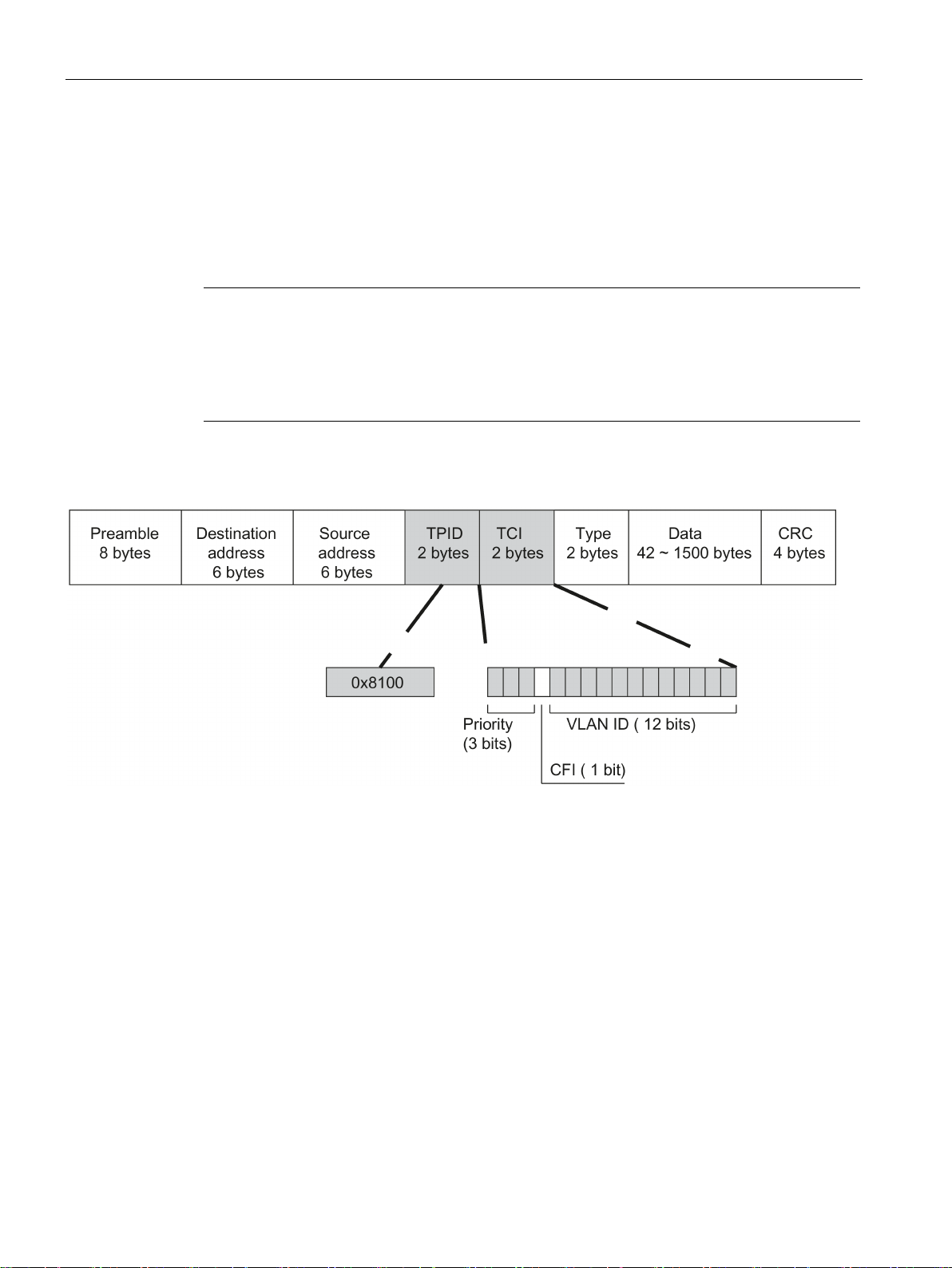
The additional 4 bytes are located in the header of the Ethernet frame between the source
address and the Ethernet type / length field:
Figure 2-1 Structure of the expanded Ethernet frame
The additional bytes contain the tag protocol identifier (TPID) and the tag control information
(TCI).
The first 2 bytes form the Tag Protocol Identifier (TPID) and always have the value 0x8100.
This value specifies that the data packet contains VLAN information or priority information.
SCALANCE S615 Web Based Management
22 Configuration Manual, 05/2015, C79000-G8976-C388-02

Technical basics
Tag Control Information (TCI)
CoS prioritization
CoS bits
Type of data
000
Non time-critical data traffic (less then best effort [basic setting])
010
Reserved (standard)
100
Data transfer with max. 100 ms delay
101
Guaranteed service, interactive multimedia
110
Guaranteed service, interactive voice transmission
111
Reserved
Canonical Format Identifier (CFI)
Value
Meaning
address, the least significant bit is transferred first. Standard-setting for Ethernet switches.
1
The format of the MAC address is not canonical.
VLAN ID
VLAN ID
Meaning
VLAN identifier.
ty information.
4095
Reserved
2.2 VLAN
The 2 bytes of the Tag Control Information (TCI) contain the following information:
The tagged frame has 3 bits for the priority that is also known as Class of Service (CoS). The
priority according to IEEE 802.1p is as follows:
001 Normal data traffic (best effort [background])
011 Reserved ( excellent effort )
The prioritization of the data packets is possible only if there is a queue in the components in
which they can buffer data packets with lower priority.
The device has multiple parallel queues in which the frames with different priorities can be
processed. First, the frames with the highest priority ("Strict Priority" method) are processed.
This method ensures that the frames with the highest priority are sent even if there is heavy
data traffic.
The CFI is required for compatibility between Ethernet and the token Ring.
The values have the following meaning:
0 The format of the MAC address is canonical. In the canonical representation of the MAC
In the 12-bit data field, up to 4096 VLAN IDs can be formed. The following conventions
apply:
0 The frame contains only priority information (priority tagged frames) and no valid
1 - 4094 Valid VLAN identifier, the frame is assigned to a VLAN and can also include priori-
SCALANCE S615 Web Based Management
Configuration Manual, 05/2015, C79000-G8976-C388-02
23

Technical basics
2.3
NAT
IP masquerading
NAPT
from
to
Response
port
translation.
a single port
a single port
The frames are translated to the port.
a port range
a single port
The frames from the port range are translated to the same port (n:1).
port range
port translation.
With individual connection, they are normally translated to the first port
used to translate to a free port in the target range.
robin method is used to translate to a free port in the target range.
2.3 NAT
NAT (Network Address Translation) is a method of translating IP addresses in data packets.
With this, two different networks (internal and external) can be connected together.
A distinction is made between source NAT in which the source IP address is translated and
destination NAT in which the destination IP address is translated.
IP masquerading is a simplified source NAT. With each outgoing data packet sent via this
interface, the source IP address is replaced by the IP address of the interface. The adapted
data packet is sent to the destination IP address. For the destination host it appears as if the
queries always came from the same sender. The internal nodes cannot be reached directly
from the external network. By using NAPT, the services of the internal nodes can be made
reachable via the external IP address of the device.
IP masquerading can be used if the internal IP addresses cannot or should not be forwarded
externally, for example because the internal network structure should remain hidden.
You configure masquerading in "Layer 3" > "NAT" > "IP Masquerading (Page 138)".
NAPT (Network Address and Port Translation) is a form of destination NAT and is often
called port forwarding. This allows the services of the internal nodes to be reached from
external that are hidden by IP masquerading or source NAT.
Incoming data packets are translated that come from the external network and are intended
for an external IP address of the device (destination IP address). The destination IP address
is replaced by the IP address of the internal node. In addition to address translation, port
translation is also possible.
The options are available for port translation:
a single port the same
a port range the same
a port range another port
range
If the ports are the same, the frames will be forwarded without port
If the port ranges are the same, the frames will be forwarded without
The frames are translated to any free port from the target range.
in the target range.
If there are connections at the same time, the round robin method is
a single port a port range The frames are translated to any free port from the target range. With
individual connection, they are normally translated to the first port in
the target range. If there are connections at the same time, the round
SCALANCE S615 Web Based Management
24 Configuration Manual, 05/2015, C79000-G8976-C388-02

Technical basics
Source NAT
NETMAP
See also
2.3 NAT
Port forwarding can be used to allow external nodes access to certain services of the internal
network e.g. FTP, WBM.
You configure NAPT in "Layer 3" > "NAT" > "NAPT (Page 139)".
As in masquerading, in source NAT the source address is translated. In addition to this, the
outgoing data packets can be restricted. These include limitation to certain IP addresses or
IP address ranges and limitation to certain interfaces. These rules can also be applied to
VPN connections.
Source NAT can be used if the internal IP addresses cannot or should not be forwarded
externally, for example because a private address range such as 192.168.x.x is used.
You configure source NAT in "Layer 3" > "NAT" > "Source NAT (Page 141)".
With NETMAP it is possible to translate complex subnets to a different subnet. In this
translation, the subnet part of the IP address is changed and the host part remains. For
translation with NETMAP only one rule is required. NETMAP can translate both the source
IP address and the destination IP address. To perform the translation with destination NAT
and source NAT, numerous rules would be necessary. NETMAP can also be applied to VPN
connections.
You configure 1:1 NAT in "Layer 3" > "NAT" > "NETMAP (Page 143)".
NAPT (Page 139)
SCALANCE S615 Web Based Management
Configuration Manual, 05/2015, C79000-G8976-C388-02
25

Technical basics
2.4
SNMP
Introduction
Note
Because the SNMP community strings are used for access protection, do not use the
standard values "public" or "private". Change these values following the initial
commissioning.
2.4 SNMP
With the aid of the Simple Network Management Protocol (SNMP), you monitor and control
network components from a central station, for example routers or switches. SNMP controls
the communication between the monitored devices and the monitoring station.
Tasks of SNMP:
● Monitoring of network components
● Remote control and remote parameter assignment of network components
● Error detection and error notification
In versions v1 and v2c, SNMP has no security mechanisms. Each user in the network can
access data and also change parameter assignments using suitable software.
For the simple control of access rights without security aspects, community strings are used.
The community string is transferred along with the query. If the community string is correct,
the SNMP agent responds and sends the requested data. If the community string is not
correct, the SNMP agent discards the query. Define different community strings for read and
write permissions. The community strings are transferred in plain text.
Standard values of the community strings:
● public
has only read permissions
● private
has read and write permissions
Further simple protection mechanisms at the device level:
● Allowed Host
The IP addresses of the monitoring systems are known to the monitored system.
● Read Only
If you assign "Read Only" to a monitored device, monitoring stations can only read out
data but cannot modify it.
SNMP data packets are not encrypted and can easily be read by others.
The central station is also known as the management station. An SNMP agent is installed on
the devices to be monitored with which the management station exchanges data.
SCALANCE S615 Web Based Management
26 Configuration Manual, 05/2015, C79000-G8976-C388-02

Technical basics
SNMPv3
2.4 SNMP
The management station sends data packets of the following type:
● GET
Request for a data record from the agent
● GETNEXT
Calls up the next data record.
● GETBULK (available as of SNMPv2)
Requests multiple data records at one time, for example several rows of a table.
● SET
Contains parameter assignment data for the relevant device.
The SNMP agent sends data packets of the following type:
● RESPONSE
The agent returns the data requested by the manager.
● TRAP
If a certain event occurs, the SNMP agent itself sends traps.
SNMPv1/v2/v3 use UDP (User Datagram Protocol) and use the UDP ports 161 and 162. The
data is described in a Management Information Base (MIB).
Compared with the previous versions SNMPv1 and SNMPv2. SNMPv3 introduces an
extensive security concept.
SNMPv3 supports:
● Fully encrypted user authentication
● Encryption of the entire data traffic
● Access control of the MIB objects at the user/group level
SCALANCE S615 Web Based Management
Configuration Manual, 05/2015, C79000-G8976-C388-02
27

Technical basics
2.5
Security functions
2.5.1
Firewall
Stateful inspection firewall
2.5 Security functions
The security functions of the device include a stateful inspection firewall. This is a method of
packet filtering or packet checking. The IP packets are checked based on firewall rules in
which the following is specified:
● The permitted protocols
● IP addresses and ports of the permitted sources
● IP addresses and ports of the permitted destinations
If an IP packet fits the specified parameters, it is allowed to pass through the firewall. The
rules also specify what is done with IP packets that are not allowed to pass through the
firewall.
Simple packet filter techniques require two firewall rules per connection.
● One rule for the query direction from the source to the destination.
● A second rule for the response direction from the destination to the source
With a stateful inspection firewall, on the other hand, you only need to specify one firewall
rule for the query direction from the source to the destination. The second rule is added
implicitly. The packet filter recognizes when, for example, computer "A" is communicating
with computer "B" and only then does it allow replies. A query by computer "B" is therefore
not possible without a prior request by computer "A".
You configure the firewall in "Security > Firewall (Page 152)".
SCALANCE S615 Web Based Management
28 Configuration Manual, 05/2015, C79000-G8976-C388-02

Technical basics
2.5.2
IPsecVPN
Roadwarrior mode
Standard mode
The IPsec method
AH
ESP
2.5 Security functions
The device is capable of establishing up to 20 IPsecVPN connections to a remote network.
You configure the IPsec connections in "Security" > " IPsec VPN (Page 159)".
With IPsecVPN, the frames are transferred in tunnel mode. To allow the device to establish a
VPN tunnel, the remote network must have a VPN gateway as the partner.
For the VPN connections, the device distinguishes two modes:
●
In this mode, the device can only operate as a VPN server. The device can only wait for
VPN connections but cannot establish a VPN tunnel as the active partner. The address of
the partner does not need to be known in this mode. This means that it is also possible to
use a dynamic IP address.
●
In standard mode, the address of the VPN gateway of the partner must be known so that
the VPN connection can be established. The device can either establish the connection
actively as a VPN client or wait passively for connection establishment by the partner.
The device uses the IPsec method in the tunnel mode for the VPN tunnel. Here, the frames
to be transferred are completely encrypted and provided with a new header before they are
sent to the VPN gateway of the partner. The frames received by the partner are decrypted
and forwarded to the recipient.
To provide security, the IPsec protocol suite uses various protocols:
● The IP Authentication Header (
source.
● The Encapsulation Security Payload (
) handles the authentication and identification of the
) encrypts the data.
SCALANCE S615 Web Based Management
Configuration Manual, 05/2015, C79000-G8976-C388-02
29

Technical basics
IKE
Authentication method
Local ID and remote ID
2.5 Security functions
● The Security Association (SA) contains the specifications negotiated between the partner,
e.g. about the lifetime of the key, the encryption algorithm, the period for new
authentication etc.
● Internet Key Exchange (
two phases:
– Phase 1
In this phase, no security services such as encryption, authentication and integrity
checks are available yet since the required keys and the IPsec SA still need to be
created. Phase 1 serves to establish a secure VPN tunnel for phase 2. To achieve
this, the communications partners negotiate an ISAKMP Security Association
(ISAKMP SA) that defines the required security services (algorithms, authentication
methods used). The subsequent messages and phase 2 are therefore secure.
– Phase 2
Phase 2 serves to negotiate the required IPsec SA. Similar to phase 1, exchanging
offers achieves agreement about the authentication methods, the algorithms and the
encryption method to protect the IP packets with IPsec AH and IPsec ESP.
The exchange of messages is protected by the ISAKMP SA negotiated in phase 1.
Due to the ISAKMP SA negotiated in phase 1, the identity of the nodes is known and
the method for the integrity check already exists.
) is a key exchange method. The key exchange takes place in
● CA certificate, device and partner certificate (digital signatures)
The use of certificates is an asymmetrical cryptographic system in which every node
(device) has a pair of keys. Each node has a secret, private key and a public key of the
partner. The private key allows the device to authenticate itself and to generate digital
signatures.
● Pre-shared key
The use of a pre-shared key is a symmetrical cryptographic system. Each node has only
one secret key for decryption and encryption of data packets. The authentication is via a
common password.
The local ID and the remote ID are used by IPsec to uniquely identify the partners (VPN end
point) during establishment of a VPN connection.
SCALANCE S615 Web Based Management
30 Configuration Manual, 05/2015, C79000-G8976-C388-02

Technical basics
Encryption methods
Requirements of the VPN partner
NAT-T
Dead peer detection
2.5 Security functions
The device also supports the following methods:
● 3DES-168
● AES-128
AES-128 is a commonly used method and is therefore set as default.
● AES-192
● AES-256
The VPN partner must support IPsec with the following configuration to be able to establish
an IPsec connection successfully:
● Authentication with partner certificate, CA certificates or pre-shared key
● IKEv1 or IKEv2
● Support of at least one of the following DH groups: Diffie-Hellman group 1, 2, 5 and 14 - 1
● 3DES or AES encryption
● MD5, SHA1 or SHA512
● Tunnel mode
If the VPN partner is downstream from a NAT router, the partner must support NAT-T. Or,
the NAT router must know the IPsec protocol (IPsec/VPN passthrough).
There may be a NAT router between the device and the VPN gateway of the remote
network. Not all NAT routers allow IPsec frames to pass through. This means that it may be
necessary to encapsulate the IPsec frames in UDP packets to be able to pass through the
NAT router.
This is only possible when the VPN partner supports DPD. DPD checks whether the
connection is still operating problem free or whether there has been an interruption on the
line. Without DPD and depending on the configuration, it may be necessary to wait until the
SA lifetime has expired or the connection must be reinitiated manually. To check whether the
IPsec connection is still problem-free, the device itself sends DPD queries to the partner
station. If the partner does not reply, the IPsec connection is considered to be interrupted
after a number of permitted failures.
SCALANCE S615 Web Based Management
Configuration Manual, 05/2015, C79000-G8976-C388-02
31

Technical basics
2.5.3
Certificates
Certificate types
Certificate
Is used in...
exchange of key files is necessary.
the validity date of the CA.
itself.
the device.
File types
File type
Description
*.crt
File that contains the certificate.
the local station, the signed certificate of the CA and the public key of the CA.
2.5 Security functions
The device uses different certificates to authenticate the various nodes.
CA certificate The CA certificate is a certificate issued by a Certificate Authority from
which the server, device and partner certificates are derived. To allow a
certificate to be derived, the CA certificate has a private key signed by the
certificate authority.
The key exchange between the device and the VPN gateway of the partner
takes place automatically when establishing the connection. No manual
Server certificate Server certificates are required to establish secure communication (e.g.
HTTPS, VPN...) between the device and another network node. The server
certificate is an encrypted SSL certificate. The server certificate is derived
from the oldest valid CA, even if this is "out of service". The crucial thing is
Device certificate Certificates with the private key (key file) with which the device identifies
Partner certificate Certificates with which the VPN gateway of the partner identifies itself with
*.p12 In the PKCS12 certificate file, the private key is stored with the corresponding certif-
icate and is password protected.
The CA creates a certificate file (PKCS12) for both ends of a VPN connection with
the file extension ".p12". This certificate file contains the public and private key of
IPsecVPN (Page 164)
SINEMA RC (Page 121)
IPsecVPN (Page 164)
IPsecVPN (Page 164)
*.pem Certificate and key as Base64-coded ASCII text.
SCALANCE S615 Web Based Management
32 Configuration Manual, 05/2015, C79000-G8976-C388-02

3
General
Physical access
Software (security functions)
Passwords
To prevent unauthorized access, note the following security recommendations.
● You should make regular checks to make sure that the device meets these
recommendations and/or other security guidelines.
● Evaluate your plant as a whole in terms of security. Use a cell protection concept with
suitable products.
● Limit physical access to the device to qualified personnel.
The memory card or the PLUG (C-PLUG, KEY-PLUG) contains sensitive data such as
certificates, keys etc. that can be read out and modified.
● Lock unused physical ports on the device. Unused ports can be used to gain forbidden
access to the plant.
● Keep the software up to date. Check regularly for security updates of the product.
You will find information on this at: Link to the area "Industrial Communication"
(http://support.automation.siemens.com/WW/view/en/10805878/133400)
● Only activate protocols that you really require to use the device.
● The option of VLAN structuring provides good protection against DoS attacks and
unauthorized access. Check whether this is practical or useful in your environment.
● Restrict access to the device by firewall, VPN (IPsec, OpenVPN) and NAT.
● Enable logging functions. Use the central logging function to log changes and access
attempts centrally. Check the logging information regularly.
● Configure a Syslog server to forward all logs to a central location.
● Define rules for the use of devices and assignment of passwords.
● Regularly update passwords and keys to increase security.
● Change all default passwords for users before you operate the device.
● Only use passwords with a high password strength. Avoid weak passwords for example
password1, 123456789, abcdefgh.
SCALANCE S615 Web Based Management
Configuration Manual, 05/2015, C79000-G8976-C388-02
33

Security recommendation
Keys and certificates
Secure/non-secure protocols
● Make sure that all passwords are protected and inaccessible to unauthorized personnel.
● Do not use the same password for different users and systems or after it has expired.
This section deals with the security keys and certificates you require to set up SSL, IPsec
and SINEMA RC.
● We strongly recommend that you create your own SSL certificates and make them
available.
There are preset certificates and keys on the device. The preset and automatically
created SSL certificates are self-signed. We recommend that you use SSL certificates
signed either by a reliable external or by an internal certification authority.
The device has an interface via which you can import the certificates and keys.
● We recommend that you use certificates with a key length of 2048 bits.
● Check whether use of SNMPv1 is necessary. SNMPv1 is classified as non-secure. Use
the option of preventing write access. The product provides you with suitable setting
options.
● For the DCP function, enable the "DCP read-only" mode after commissioning.
● If SNMP is enabled, change the community names. If no unrestricted access is
necessary, restrict access with SNMP.
● Use secure protocols when access to the device is not prevented by physical protection
measures.
The following protocols provide secure alternatives:
– SNMPv1 → SNMPv3
– HTTP → HTTPS
– Telnet → SSH
– SNTP → NTP (secure)
● Avoid or disable non-secure protocols, for example Telnet and TFTP. For historical
reasons, these protocols are still available, however not intended for secure applications.
Use non-secure protocols with caution.
● To prevent unauthorized access to the device or network, take suitable protective
measures against non-secure protocols.
SCALANCE S615 Web Based Management
34 Configuration Manual, 05/2015, C79000-G8976-C388-02

Security recommendation
Available protocols per port
Protocol
Port number
Port status
Note
With some protocols the port may be open although the corresponding protocol is
disabled, for example TFTP.
Default status of the port
Authentication
Protocol
Port number
Port status
Default status of
the port
Authentication
SSH
TCP/22
Open
Open
Yes
HTTP
TCP/80
Open
Open
Yes
HTTPS
TCP/443
Open
Open
Yes
SNTP
(when configured)
SNMP
(when configured)
SNMP trap
(when configured)
The following list provides you with an overview of the open ports on this device. Keep this in
mind when configuring a firewall.
The table includes the following columns:
●
All protocols that the device supports
●
Port number assigned to the protocol
●
– Open
– Open (when configured)
The port is always open and cannot be closed.
The port is open if it has been configured.
●
– Open
As default the port is open.
– Closed
As default the port is closed.
●
Specifies whether or not the protocol is authenticated during access.
UDP/123 Open
UDP/161 Open
UDP/162 Open
Closed No
Open Yes
Open Yes
SCALANCE S615 Web Based Management
Configuration Manual, 05/2015, C79000-G8976-C388-02
35

Security recommendation
SCALANCE S615 Web Based Management
36 Configuration Manual, 05/2015, C79000-G8976-C388-02

4
4.1
Web Based Management
How it works
Note
Secure connection
WBM also allows you to establish a secure connection via HTTPS.
Use HTTPS for protected data transmission. If you want to access WBM only via a secure
connection, under "System >
Requirements
WBM display
The device has an integrated HTTP server for Web Based Management (WBM). If a device
is addressed with a Web browser, it returns HTML pages to the Admin PC depending on the
user input.
The user enters the configuration data in the HTML pages sent by the device. The device
evaluates this information and generates reply pages dynamically.
Configuration" enable the option "HTTPS Server only".
● The device has an IP address.
● There is a connection between the device and the Admin PC. With the Windows ping
command, you can check whether or not a connection exists. If the device has the factory
settings, refer to "Requirements for operation (Page 13)".
● Access using HTTP or HTTPS is enabled.
● JavaScript is activated in the Web browser.
● The Web browser must not be set so that it reloads the page from the server each time
the page is accessed. The updating of the dynamic content of the page is ensured by
other mechanisms.
In the Internet Explorer, you can make the appropriate setting in the "Options > Internet
Options > General" menu in the section "Browsing history" with the "Settings" button.
Check whether "Automatically" is enabled for "Check for newer versions of stored pages".
SCALANCE S615 Web Based Management
Configuration Manual, 05/2015, C79000-G8976-C388-02
37

Configuring with Web Based Management
Note
Compatibility view
In Microsoft Internet Explorer, disable the compatibility view to ensure correct display
and to allow problem
4.1 Web Based Management
● If a firewall is used, the relevant ports must be opened.
– For access using HTTP: Port 80
– For access using HTTPS: Port 443
● The display of the WBM was tested with the following desktop Web browsers:
– MS IE 9
-free configuration using WBM.
– Mozilla Firefox ESR17
SCALANCE S615 Web Based Management
38 Configuration Manual, 05/2015, C79000-G8976-C388-02

Configuring with Web Based Management
4.2
Starting and logging in
Establishing a connection to a device
Logging in using the Internet browser
Selecting the language of the WBM
Note
Available languages
in this version, only English is available.
4.2 Starting and logging in
Follow the steps below to establish a connection to a device using an Internet browser:
1. There is a connection between the device and the Admin PC. With the ping command,
you can check whether or not a connection exists.
2. In the address box of the Internet browser, enter the IP address or the URL of the device.
If there is a problem-free connection to the device, the logon page of Web Based
Management (WBM)is displayed.
1. From the drop-down list at the top right, select the language version of the WBM pages.
2. Click the "Go" button to change to the selected language.
Other languages will follow in a later version.
SCALANCE S615 Web Based Management
Configuration Manual, 05/2015, C79000-G8976-C388-02
39

Configuring with Web Based Management
Logon with HTTP
Logon with HTTPS
4.2 Starting and logging in
There are two ways in which you can log on via HTTP. You either use the logon option in the
center of the browser window or the logon option in the upper left area of the browser
window.
1. Enter the user name "admin".
2. Enter the corresponding password.
When you log on the first time or following a "Restore Factory Defaults and Restart",
enter the default password "
3. Click the "Login" button or confirm your entry with "Enter".
When you log on for the first time or following a "Restore Factory Defaults and Restart",
you will be prompted to change the password. The new password should meet the
following password policies:
– Password length: at least 8 characters
– at least 1 uppercase letter
– at least 1 special character
– at least 1 number
admin".
Once you have logged in successfully, the start page appears.
Web Based Management also allows you to connect to the device over the secure
connection of the HTTPS protocol. Follow these steps:
1. Click on the link "Switch to secure HTTP" on the logon page or enter "https://" and the IP
2. Confirm the displayed certificate warning.
3. Enter the user name "admin". Enter the corresponding password. When you log on the
You need to repeat the password as confirmation. The password entries must match.
Click the "Set Values" to complete the action and activate the new password.
address of the device in the address box of the Internet browser.
The logon page of Web Based Management appears.
first time or following a "Restore Factory Defaults and Restart", enter the default
password "admin".
SCALANCE S615 Web Based Management
40 Configuration Manual, 05/2015, C79000-G8976-C388-02

Configuring with Web Based Management
4.2 Starting and logging in
4. Click the "Login" button or confirm your entry with "Enter".
When you log on for the first time or following a "Restore Factory Defaults and Restart",
you will be prompted to change the password. The new password should meet the
following password policies:
– Password length: at least 8 characters
– at least 1 uppercase letter
– at least 1 special character
– at least 1 number
You need to repeat the password as confirmation. The password entries must match.
Click the "Set Values" to complete the action and activate the new password.
Once you have logged in successfully, the start page appears.
SCALANCE S615 Web Based Management
Configuration Manual, 05/2015, C79000-G8976-C388-02
41

Configuring with Web Based Management
4.3
"Information" menu
4.3.1
Start page
View of the Start page
General layout of the WBM page
4.3 "Information" menu
When you enter the IP address of the device, the start page is displayed after a successful
login.
The following areas are available on every WBM page:
● Selection area (1): Top area
● Display area (2): Top area
● Navigation area (3): Left-hand area
● Content area (4): Middle area
SCALANCE S615 Web Based Management
42 Configuration Manual, 05/2015, C79000-G8976-C388-02

Configuring with Web Based Management
Selection area (1)
4.3 "Information" menu
The following is available in the selection area:
● Logo of Siemens AG
● Display of: "System Location/System Name".
– "System Location" contains the location of the device.
With the settings when the device ships, the IP address of the Ethernet interface is
displayed.
– "System Name" is the device name.
You can change the content of this display with "System" > "General" > "Device".
SCALANCE S615 Web Based Management
Configuration Manual, 05/2015, C79000-G8976-C388-02
43

Configuring with Web Based Management
Display area (2)
Printer
Help
LED simulation
Update on / Update off
Navigation area (3)
4.3 "Information" menu
● Drop-down list for language selection
● System time and date
You can change the content of this display in "System" > "System Time".
In the left-hand part of the display area, the full title of the currently selected menu item is
always displayed.
●
When you click this button, a pop-up window opens with a view of the page content
optimized for the printer.
●
When you click this button, the help page of the currently selected menu item is opened
in a new browser window.
●
Each component of a device has one or more LEDs that provide information on the
operating state of the device. Depending on its location, direct access to the device may
not always be possible. Web Based Management therefore displays simulated LEDs. The
meaning of the LED displays is described in the operating instructions.
If you click this button, you open the window for the LED simulation. You can show this
window during a change of menu and move it as necessary. To close the LED simulation,
click the close button in the LED simulation window.
●
WBM pages with overview lists can also have the additional "Update" button.
With this button, you can enable or disable updating of the content area. If updating is
turned on, the display is updated every 2 seconds. To disable the update, click "On".
Instead of "On", "Off" is displayed. As default, updating is always enabled on the WBM
page.
In the navigation area, you have various menus available. Click the individual menus to
display the submenus. The submenus contain pages on which information is available or
with which you can create configurations. These pages are always displayed in the content
area.
SCALANCE S615 Web Based Management
44 Configuration Manual, 05/2015, C79000-G8976-C388-02

Configuring with Web Based Management
Content area (4)
Buttons you require often
Refresh the display with "Refresh"
Note
If you click the "Refresh" button, before you have transferred your configuration changes
to the device using the "Set Values" button, your changes will be
previous configuration will be loaded from the device and displayed here.
4.3 "Information" menu
In the navigation area, click a menu to display the pages of the WBM in the content area.
Below the device image, the following entries are possible:
● System Name: System name of the device
● Device Type: The type of the device
● PLUG ConfigurationShows the status of the configuration data on the PLUG, refer to the
section "System > PLUG > Configuration".
● PLUG LicenseShows the status of the license on the PLUG, refer to the section "System
> PLUG > License".
● DDNS Status
If a dynamic DNS service is used, the hostname of the device is displayed, e.g.
example.no-ip.com. The status of the update is also displayed.
– update successful
Update successful
– update failed
Update unsuccessful
– status unkown
Status unknown
● Fault Status: Displays the error status of the device.
The WBM pages contain the following standard buttons:
●
WBM pages that display current parameters have a "Refresh" button at the lower edge of
the page. Click this button to request up-to-date information from the device for the
current page.
deleted and the
SCALANCE S615 Web Based Management
Configuration Manual, 05/2015, C79000-G8976-C388-02
45

Configuring with Web Based Management
Save entries with "Set Values"
Note
Changing configuration data is possible only with the "admin"
Note
The changes take immediate effect. But it takes some time for the changes in the
configuration to be stored.
Create entries with "Create"
Delete entries with "Delete"
Page down with "Next"
Page up with "Prev"
Logout
4.3 "Information" menu
●
WBM pages in which you can make configuration settings have a "Set Values" button at
the lower edge. The button only becomes active if you change at least one value on the
page. Click this button to save the configuration data you have entered on the device.
Once you have saved, the button becomes inactive again.
login.
●
WBM pages in which you can make new entries have a "Create" button at the lower
edge. Click this button to create a new entry.
●
WBM pages in which you can delete entries have a "Delete" button at the lower edge.
Click this button to delete the previously selected entries from the device memory.
Deleting also results in an update of the page in the WBM.
●
The number of data records that can be displayed on a WBM page is limited. Click the
"Next" button to page down through the data records.
●
The number of data records that can be displayed on a page is limited. Click the "Prev"
button to page up through the data records.
You can log out from any WBM page by clicking the "Logout" link.
SCALANCE S615 Web Based Management
46 Configuration Manual, 05/2015, C79000-G8976-C388-02

Configuring with Web Based Management
4.3.2
Versions
Description
Hardware
Name
Revision
Order ID
Software
Description
Version
Date
4.3 "Information" menu
This WBM page shows the versions of the hardware and software of the device.
Table 1 has the following columns:
●
– Basic Device
●
Shows the name of the device.
●
Shows the hardware version of the device.
●
Shows the order number of the device.
●
– Firmware
– Bootloader
– Firmware_Running
–
●
Shows the short description of the software.
Shows the basic device
Shows the current firmware version. If a new firmware file was loaded and the device
has not yet restarted, the firmware version of the loaded firmware file is displayed.
After the next restart, the loaded firmware is activated and used.
Shows the version of the boot software stored on the device.
Shows the firmware version currently being used on the device.
●
Shows the version number of the software.
●
Shows the date the software was created.
SCALANCE S615 Web Based Management
Configuration Manual, 05/2015, C79000-G8976-C388-02
47

Configuring with Web Based Management
4.3.3
ARP Table
Assignment of MAC address and IP address
Description
Interface
MAC Address
IP Address
Media Type
4.3 "Information" menu
With the Address Resolution Protocol (ARP), there is a unique assignment of MAC address
to IP address. This assignment is kept by each network node in its own separate ARP table.
The WBM page shows the ARP table of the device.
The table has the following columns:
●
Shows the interface via which the row entry was learnt.
●
Shows the MAC address of the target or source device.
●
Shows the IP address of the target device.
●
Shows the type of connection.
– Dynamic
– Static
The device recognized the address data automatically.
The addresses were entered as static addresses.
SCALANCE S615 Web Based Management
48 Configuration Manual, 05/2015, C79000-G8976-C388-02

Configuring with Web Based Management
4.3.4
Log tables
4.3.4.1
Event log
Logging events
Description
Severity Filters
4.3 "Information" menu
The WBM page shows the system events that have occurred in the form of a table. Some of
the system events can be configured in "System > Events", for example if the connection
status of a port has changed.
The content of the table is retained even when the device is turned off. The event log file can
be loaded using HTTP on TFTP.
●
You can filter the entries in the table according to severity. To display all the entries,
enable or disable all parameters.
– 2 - Critical
Critical
– 4 - Warning
Warnings
– 6- Info
Informative
SCALANCE S615 Web Based Management
Configuration Manual, 05/2015, C79000-G8976-C388-02
49

Configuring with Web Based Management
Restart
System Up Time
System time
Severity
Log Message
Description of the button
"Clear" button
Note
The number of entries in this table is restricted to 400 per degree of severity. When this
number is reached, the
memory.
"Show all" button
"Next" button
"Prev" button
Drop-down list for page change
4.3 "Information" menu
The table has the following columns:
●
Counts the number of restarts since you last reset to factory settings and shows the
device restart after which the corresponding event occurred.
●
Shows the time the device has been running since the last restart when the described
event occurred.
●
Shows the system time of the device. If no system time is set, the box displays "Date/time
not set".
●
Shows the severity of the event.
●
Displays a brief description of the event that has occurred.
Click this button to delete the content of the log file. The display is also cleared. The restart
counter is only reset after you have restored the device to the factory settings and restarted
the device.
oldest entries are overwritten. The table remains permanently in
Click this button to display all the entries on the WBM page. Note that displaying all
messages can take some time.
Click this button to go to the next page.
Click this button to go to the previous page.
From the drop-down list, select the page you want to go to.
SCALANCE S615 Web Based Management
50 Configuration Manual, 05/2015, C79000-G8976-C388-02

Configuring with Web Based Management
4.3.4.2
Security log
Description
Severity Filters
Restart
System Up Time
4.3 "Information" menu
The WBM page shows the events that occurred during communication via a secure VPN
tunnel in the form of the table.
●
You can filter the entries in the table according to severity. To display all messages,
enable or disable all parameters.
– 2 - Critical
Critical
– 4 - Warning
Warnings
– 6 - Info
Informative
The table has the following columns:
●
Counts the number of restarts since you last reset to factory settings and shows the
device restart after which the corresponding message occurred.
●
Shows the time the device has been running since the last restart when the event
occurred.
SCALANCE S615 Web Based Management
Configuration Manual, 05/2015, C79000-G8976-C388-02
51

Configuring with Web Based Management
System time
Severity
Log Message
Description of the button
"Clear" button
Note
The number of entries in this table is restricted to 400 per degree of severity. When this
number is reached, the oldest entries are overwritten. The table remains permanently in
memory.
"Show all" button
"Next" button
"Prev" button
Drop-down list for page change
4.3 "Information" menu
●
Shows the system time of the device. If no system time is set, the box displays "Date/time
not set".
●
Shows the severity of the event.
●
Displays a brief description of the event that has occurred.
If the system time is set, the time is also displayed at which the event occurred.
Click this button to delete the content of the log file. The display is also cleared. The restart
counter is only reset after you have restored the device to the factory settings and restarted
the device.
Click this button to display all the entries on the WBM page. Note that displaying all
messages can take some time.
Click this button to go to the next page.
Click this button to go to the previous page.
From the drop-down list, select the page you want to go to.
SCALANCE S615 Web Based Management
52 Configuration Manual, 05/2015, C79000-G8976-C388-02

Configuring with Web Based Management
4.3.4.3
Firewall log
Description
Severity Filters
Restart
System Up Time
System time
4.3 "Information" menu
The firewall log logs the events that occurred on the firewall. When you create firewall rules,
you can specify the event severity with which they are logged.
●
You can filter the entries in the table according to severity. To display all the entries,
enable or disable all parameters.
– 2 - Critical
Critical
– 4 - Warning
Warnings
– 6- Info
Informative
The table has the following columns:
●
Counts the number of restarts since you last reset to factory settings and shows the
device restart after which the corresponding event occurred.
●
Shows the time the device has been running since the last restart when the described
event occurred.
●
Shows the system time of the device. If no system time is set, the box displays "Date/time
not set".
SCALANCE S615 Web Based Management
Configuration Manual, 05/2015, C79000-G8976-C388-02
53

Configuring with Web Based Management
Severity
Log Message
Description of the button
"Clear" button
Note
The number of entries in this table is restricted to 400 per degree of severity. When this
number is reached, the oldest entries are overwritten. The table remains permanently in
memory.
"Show all" button
"Next" button
"Prev" button
Drop-down list for page change
4.3 "Information" menu
●
Shows the severity of the event.
●
Displays a brief description of the event that has occurred.
Click this button to delete the content of the log file. The display is also cleared. The restart
counter is only reset after you have restored the device to the factory settings and restarted
the device.
Click this button to display all the entries on the WBM page. Note that displaying all
messages can take some time.
Click this button to go to the next page.
Click this button to go to the previous page.
From the drop-down list, select the page you want to go to.
SCALANCE S615 Web Based Management
54 Configuration Manual, 05/2015, C79000-G8976-C388-02

Configuring with Web Based Management
4.3.5
Faults
Error status
Description
No. of Signaled Faults
Fault Time
Fault Description
Clear Fault State
4.3 "Information" menu
This page shows errors that occur that are configured in "Events" and "Fault Monitoring".
Errors of the "Cold/Warm Start" event can be deleted following confirmation.
If there are no more unanswered error/fault messages, the fault LED goes off.
The time calculation always begins after the last system start. When the system is restarted,
a new entry with the type of restart is created in the fault memory.
The "
last startup. Click the "Reset Counters" button to reset this value.
The table contains the following columns:
●
Shows the time the device has been running since the last restart when the described
fault occurred.
●
Displays a brief description of the error that has occurred.
●
To delete errors of the "Cold/Warm Start" event, click the Clear Fault State" button.
" box shows the number of faults that have occurred since the
SCALANCE S615 Web Based Management
Configuration Manual, 05/2015, C79000-G8976-C388-02
55

Configuring with Web Based Management
4.3.6
DHCP Server
Description
IP Address
Pool ID
HW Type
HW Address
Allocation Method
Binding State
Expire Time
4.3 "Information" menu
This page shows whether IPv4 addresses were assigned to the devices by the DHCP
server.
●
Shows the IPv4 address assigned to the device.
●
Shows the number of the IPv4 address band.
●
Shows that the DHCP server identifies the devices in the network based on the MAC
address.
●
Shows the MAC address of the DHCP client.
●
Show whether the IPv4 address was assigned statically or dynamically. You configure the
static entries in "System > DHCP > Static Leases".
●
Shows the status of the assignment.
– assigned
– not assigned
– probing
– unknown
The assignment is used.
The assignment is not used.
The assignment is being checked.
The status of the assignment is unknown.
●
Shows how long the assigned IPv4 address is still valid. Once this period has elapsed,
the device must either request a new IPv4 address or extend the lease time of the
existing IPv4 address.
SCALANCE S615 Web Based Management
56 Configuration Manual, 05/2015, C79000-G8976-C388-02

Configuring with Web Based Management
4.3.7
LLDP
Status of the neighborhood table
Description of the displayed values
System name
Device ID
Local Interface
Hold Time
Capability
4.3 "Information" menu
This page shows the current content of the neighborhood table. This table stores the
information that the LLDP agent has received from connected devices.
You set the interfaces via which the LLDP agent receives or sends information in the
following section: "Layer 2 > LLDP".
Figure 4-1 Information LLDP
This table contains the following columns:
●
System name of the connected device.
●
Device ID of the connected device.
●
Port at which the IE switch received the information.
●
An entry remains stored in the MIB for the time specified here. If the IE switch does not
receive any new information from the connected device during this time, the entry is
deleted.
●
Shows the properties of the connected device:
– Router
– Bridge
– Telephone
SCALANCE S615 Web Based Management
Configuration Manual, 05/2015, C79000-G8976-C388-02
57

Configuring with Web Based Management
Port ID
4.3.8
Routing table
Introduction
Description
Destination Network
Subnet Mask/Prefix
Gateway
Interface
4.3 "Information" menu
– DOCSIS Cable Device
– WLAN Access Point
– Repeater
– Station
– Other
●
Port of the device with which the IE switch is connected.
This page shows the routing table of the device.
The table has the following columns:
●
Shows the destination address of this route.
●
Shows the subnet mask (IPv4) or the prefix length (IPv6) of this route.
●
Shows the gateway for this route.
●
Shows the interface for this route.
SCALANCE S615 Web Based Management
58 Configuration Manual, 05/2015, C79000-G8976-C388-02

Configuring with Web Based Management
Metric
Routing Protocol
4.3.9
IPsec VPN
Description
Name
Local Host
Local DN
Local Subnet
Remote Host
Remote DN
Remote Subnet
4.3 "Information" menu
●
Shows the metric of the route. The higher the value, the longer packets require to their
destination.
●
Shows the routing protocol from which the entry in the routing table originates. The
following entries are possible:
– Connected: Connected routes
– Static: Static routes
The WBM page shows the status of the activated VPN connections.
This table contains the following columns:
●
Shows the name of the VPN connection.
●
Shows the IP address of the device.
●
Shows the Distinguished Name (DN) of the device that was signaled to the remote station
during connection establishment. The entry is adopted from the "Local ID" box, the device
certificate or the IP address of the device.
●
Shows the local subnet.
●
Shows the IP address or the hostname of the remote device.
●
Shows the Distinguished Name (DN) signaled by the remote device during connection
establishment.
●
Shows the remote subnet.
SCALANCE S615 Web Based Management
Configuration Manual, 05/2015, C79000-G8976-C388-02
59

Configuring with Web Based Management
Rekey Time
Status
4.3.10
SINEMA RC
Note
This function can only be used with a KEY
Description
Status
Remote Address
4.3 "Information" menu
●
Shows when the validity of the key elapses.
●
Shows the status of the VPN connection.
Shows information on SINEMA RC Server.
-PLUG.
●
Shows the status of the SINEMA RC Server connection.
●
Shows the IP address of the SINEMA RC Server.
SCALANCE S615 Web Based Management
60 Configuration Manual, 05/2015, C79000-G8976-C388-02

Configuring with Web Based Management
Tunnel Interface Address
Connected Local Subnet(s)
Connected Remote Subnet(s)
Fingerprint
4.3 "Information" menu
●
Shows the IP address of the virtual tunnel interface.
●
Shows the IP address of the local subnet. Is only displayed when the option "Connected
local subnets" is enabled on the SINEMA RC Server. You will find further information on
this in the Operating Instructions of the SINEMA RC Server.
●
Shows the subnets of the SINEMA RC Server.
●
Displays the fingerprint of the server certificate. Is only displayed when the fingerprint is
used for verification.
SCALANCE S615 Web Based Management
Configuration Manual, 05/2015, C79000-G8976-C388-02
61

Configuring with Web Based Management
4.4
"System" menu
4.4.1
Configuration
System configuration
Description
"Telnet Server" check box
"SSH Server" check box
"HTTPS Server only" check box
"SMTP Client" check box
4.4 "System" menu
The WBM page contains the configuration overview of the access options of the device.
Specify the services that access the device. With some services, there are further
configuration pages on which more detailed settings can be made.
The page contains the following boxes:
●
Enable or disable the "Telnet Server" service for unencrypted access to the CLI.
●
Enable or disable the "SSH Server" service for encrypted access to the CLI.
●
When this function is enabled, you can only access the device using HTTPS.
●
Enable or disable the SMTP client. You can configure other settings in "System > SMTP
Client".
SCALANCE S615 Web Based Management
62 Configuration Manual, 05/2015, C79000-G8976-C388-02

Configuring with Web Based Management
"Syslog Client"
"DCP Server"
"Time"
"SNMP" drop-down list:
"SNMPv1/v2 Read-Only"
4.4 "System" menu
●
check box
Enable or disable the Syslog client. You can configure other settings in "System > Syslog
Client".
●
drop-down list
Specify whether or not the device can be accessed with DCP (Discovery and
Configuration Protocol):
– "-" (disabled)
DCP is disabled. Device parameters can neither be read nor modified.
– Read/Write
With DCP, device parameters can be both read and modified.
– Read-Only
With DCP, device parameters can be read but cannot be modified.
●
drop-down list
Select the setting from the drop-down list. The following settings are possible:
– Manual
The system time is set manually. You can configure other settings in "System >
System Time > Manual Setting".
– SNTP Client
The system time is set via an SNTP server. You can configure other settings in
"System > System Time > SNTP Client".
– NTP Client
The system time is set via an NTP server. You can configure other settings in "System
> System Time > NTP Client".
– SIMATIC Time
The system time is set using a SIMATIC time transmitter. You can configure other
settings in "System > System Time > SIMATIC Time Client".
●
Select the protocol from the drop-down list. The following settings are possible:
– "-" (SNMP disabled)
Access to device parameters via SNMP is not possible.
– SNMPv1/v2c/v3
Access to device parameters is possible with SNMP versions 1, 2c or 3. You can
configure other settings in "System > SNMP > General".
– SNMPv3
Access to device parameters is possible only with SNMP version 3. You can configure
other settings in "System > SNMP > General".
●
Enable or disable write access to SNMP variables with SNMPv1/v2c.
SCALANCE S615 Web Based Management
Configuration Manual, 05/2015, C79000-G8976-C388-02
check box
63

Configuring with Web Based Management
"SNMPv1 Traps"
"Configuration Mode" drop-down list:
Procedure
4.4 "System" menu
●
Enable or disable the sending of traps (alarm frames). You can configure other settings in
"System > SNMP > Traps".
check box
●
Select the mode from the drop-down list. The following modes are possible:
– Automatic Save
Automatic save mode. Approximately 1 minute after the last parameter change or
when you restart the device, the configuration is automatically saved.
– Trial
Trial mode. In Trial mode, although changes are adopted, they are not saved in the
configuration file (startup configuration).
To save changes in the configuration file, use the "Write Startup Config" button. The
"Write Startup Config" button is displayed when you set trial mode. The message
"Trial Mode Active – Press "Write Startup Config" button to make your settings
persistent" is also displayed in the display area as soon as there are unsaved
changes. This message can be seen on every WBM page until the changes made
have either been saved or the device has been restarted.
1. To use the required function, select the corresponding check box.
2. Select the options you require from the drop-down lists.
3. Click the "Set Values" button.
SCALANCE S615 Web Based Management
64 Configuration Manual, 05/2015, C79000-G8976-C388-02

Configuring with Web Based Management
4.4.2
General
4.4.2.1
Device
Description
Current System Time
System Up Time
Device Type
"System Name" input box
4.4 "System" menu
This WBM page contains the general device information.
The WBM page contains the following boxes:
●
Shows the current system time. The system time is either set by the user or by a time-ofday frame: either SINEC H1 time-of-day frame, NTP or SNTP.
●
Shows the operating time of the device since the last restart.
●
Shows the type designation of the device.
●
You can enter the name of the device. The name is displayed in the selection area. A
maximum of 255 characters are possible.
SCALANCE S615 Web Based Management
Configuration Manual, 05/2015, C79000-G8976-C388-02
65

Configuring with Web Based Management
"System Contact" input box
"System Location" input box
Note
Permitted characters
The following printable ASCII characters (0x20 to 0x7) are permitted in the input fields:
•
•
•
Procedure
4.4 "System" menu
●
You can enter the name of a contact person responsible for managing the device. A
maximum of 255 characters are possible.
●
You can enter the location where the device is installed. The location is displayed in the
selection area. A maximum of 255 characters are possible.
0123456789
A...Z a...z
!"#$%&'()*+,-./:;<=>?@ [\]_{|}~¦^`
1. Enter the contact person responsible for the device in the "System Contact" input box.
2. Enter the identifier for the location at which the device is installed in the "System
Location" input box.
3. Enter the name of the device in the "System Name" input box.
4. Click the "Set Values" button.
Note: Steps 1 to 3 can also be performed with the SNMP Management Tool.
SCALANCE S615 Web Based Management
66 Configuration Manual, 05/2015, C79000-G8976-C388-02

Configuring with Web Based Management
4.4.2.2
Coordinates
Information on geographic coordinates
Getting the coordinates
Description
"Latitude" input box
"Longitude" input box
4.4 "System" menu
In the "Geographic Coordinates" window, you can enter information on the geographic
coordinates. The parameters of the geographic coordinates (latitude, longitude and the
height above the ellipsoid according to WGS84) are entered directly in the input boxes of the
"Geographic Coordinates" window.
Use suitable maps for obtaining the geographic coordinates of the device.
The geographic coordinates can also be obtained using a GPS receiver. The geographic
coordinates of these devices are normally displayed directly and only need to be entered in
the input boxes of this page.
The page contains the following boxes. These are purely information boxes with a maximum
length of 32 characters.
●
Geographical latitude: Here, enter the value for the northerly or southerly latitude of the
location of the device.
For example, the value +49° 1´31.67" means that the device is located at 49 degrees, 1
arc minute and 31.67 arc seconds northerly latitude.
A southerly latitude is shown by a preceding minus character.
You can also append the letters N (northerly latitude) or S (southerly latitude) to the
numeric information (49° 1´31.67" N).
●
Geographical longitude: Here, you enter the value of the eastern or western longitude of
the location of the device.
The value +8° 20´58.73" means that the device is located at 8 degrees, 20 minutes and
58.73 seconds east.
A western longitude is indicated by a preceding minus sign.
You can also add the letter E (easterly longitude) or W (westerly longitude) to the numeric
information (8° 20´58.73" E).
SCALANCE S615 Web Based Management
Configuration Manual, 05/2015, C79000-G8976-C388-02
67

Configuring with Web Based Management
Input box: "Height"
Procedure
4.4.3
Restart
Resetting to the defaults
4.4 "System" menu
●
Geographical height: Here, you enter the value of the geographic height above sea level
in meters.
For example, 158 m means that the device is located at a height of 158 m above sea
level.
Heights below sea level (for example the Dead Sea) are indicated by a preceding minus
sign.
1. Enter the latitude in the "Latitude" input box.
2. Enter the longitude in the "Longitude" input box.
3. Enter the height in the "Height" input box.
4. Click the "Set Values" button.
In this menu, there is a button with which you can restart the device and various options for
resetting to the device defaults.
SCALANCE S615 Web Based Management
68 Configuration Manual, 05/2015, C79000-G8976-C388-02

Configuring with Web Based Management
Note
Note the following points about restarting a device:
•
•
•
Description of the displayed boxes
"Restart System" button
"Restore Memory Defaults and Restart" button
"Restore Factory Defaults and Restart" button
Note
By resetting to the factory configuration settings, the device loses its configured IP
address and is
re
4.4 "System" menu
You can only restart the device with administrator privileges.
A device should only be restarted with the buttons of this menu and not by a power cycle
on the device.
Any modifications you have made only become active on the device after clicking the "Set
Values" button on the relevant WBM page. If the device is in "Trial Mode", configuration
modifications must be saved manually before a restart. In "Autosave mode", the last
changes are saved automatically before a restart.
To restart the device, you have the following options:
●
Click this button to restart the system. You must confirm the restart in a dialog box.
During a restart, the device is reinitialized, the internal firmware is reloaded, and the
device runs a self-test. The learned entries in the address table are deleted. You can
leave the browser window open while the device restarts. You then need to log in again.
●
Click this button to restore the factory configuration settings with the exception of the
following parameters and to restart:
– IP addresses
– Subnet mask
– IP address of the default gateway
– DHCP client ID
– DHCP
– System name
– System location
– System contact
– User names and passwords
●
Click on this button to restore the factory configuration settings. The protected defaults
are also reset.
An automatic restart is triggered.
achable again with the IP address 192.168.1.1 set in the factory.
SCALANCE S615 Web Based Management
Configuration Manual, 05/2015, C79000-G8976-C388-02
69

Configuring with Web Based Management
4.4.4
Load and Save
4.4.4.1
HTTP
Loading and saving data using HTTP
Note
Configuration files and trial mode/Automatic Save mode
In Automatic Save mode, the data is saved automatically before the configuration files
(ConfigPack and Config) are transferred.
In Trial, although the changes are adopted, they are not saved in the
(ConfigPack and Config). Use the "Write Startup Config" button on the "System >
Configuration" WBM page to save changes in the configuration files.
Description
Type
Description
4.4 "System" menu
The WBM allows you to store device data in an external file on your client PC or to load such
data from an external file from the PC to the devices. This means, for example, that you can
also load new firmware from a file located on your Admin PC. On this page, the certificates
required to establish a secure VPN connection can also be loaded.
configuration files
The table has the following columns:
●
Shows the file type.
●
SCALANCE S615 Web Based Management
70 Configuration Manual, 05/2015, C79000-G8976-C388-02
Shows the short description of the file type.

Configuring with Web Based Management
Load
Save
Delete
Note
Following a firmware update, empty the cache of the Web browser.
Procedure
Loading files using HTTP
Note
Files whose access is password protected
To be able to load these files on the device successfully, you need to enter the password
specified for the
Saving files using HTTP
Deleting files using HTTP
4.4 "System" menu
●
With this button, you can load files on the device. The button can be enabled, if this
function is supported by the file type.
●
With this button, you can save files from the device. The button can only be enabled if
this function is supported by the file type and the file exists on the device.
●
With this button, you can delete files from the device. The button can only be enabled if
this function is supported by the file type and the file exists on the device.
1. Start the load function by clicking the one of the "Load" buttons.
The dialog for loading a file is opened.
file in "System" > "Load & Save" > "Password".
2. Go to the required file
3. Click the "Open" button in the dialog.
The file is now loaded.
4. If a restart is necessary, a message to this effect will be output.
1. Start the save function by clicking the one of the "Save" buttons.
2. You will be prompted to select a storage location and a name for the file. Or you accept
the proposed file name. To make the selection, use the dialog in your browser. After
making your selection, click the "Save" button.
1. Start the delete function by clicking the one of the "Delete" buttons.
The file will be deleted.
SCALANCE S615 Web Based Management
Configuration Manual, 05/2015, C79000-G8976-C388-02
71

Configuring with Web Based Management
Reusing configuration data
4.4 "System" menu
If several devices are to receive the same configuration and the IP addresses are assigned
using DHCP, the effort for configuration can be reduced by saving and reading in the
configuration data.
Follow the steps below to reuse configuration data:
1. Save the configuration data of a configured device on your PC.
2. Load this configuration file on all other devices you want to configure.
3. If individual settings are necessary for specific devices, these must be made online on the
relevant device.
Note that the configuration data is coded when it is saved. This means that you cannot edit
the files with a text editor.
SCALANCE S615 Web Based Management
72 Configuration Manual, 05/2015, C79000-G8976-C388-02

Configuring with Web Based Management
4.4.4.2
TFTP
Loading and saving data using a TFTP server
Note
Configuration files and trial mode/Automatic Save mode
In Automatic Save mode, the data is saved automatically before the configuration files
(ConfigPack and Config)
In Trial, although the changes are adopted, they are not saved in the configuration files
(ConfigPack and Config). Use the "Write Startup Config" button on the "System >
Configuration" WBM page to save changes in the configuration files.
Description
"TFTP Server IP Address" input box
"TFTP Server IP Port" input box
4.4 "System" menu
On this page, you can configure the TFTP server and the file names. The WBM also allows
you to store device data in an external file on your client PC or to load such data from an
external file from the PC to the devices. This means, for example, that you can also load new
firmware from a file located on your Admin PC.
On this page, the certificates required to establish a secure VPN connection can also be
loaded.
are transferred.
The page contains the following boxes:
●
Enter the IP address of the TFTP server with which you exchange data.
●
Enter the port of the TFTP server over which data exchange will be handled. If
necessary, you can change the default value 69 to your own requirements.
SCALANCE S615 Web Based Management
Configuration Manual, 05/2015, C79000-G8976-C388-02
73

Configuring with Web Based Management
Type
Description
"Filename" input box
"Actions" drop-down list
Save file
Load file
Procedure
Loading files using TFTP
Note
Files whose access is password protected
To be able to load these files on the device successfully, you need to enter the password
specifi
Reusing configuration data
4.4 "System" menu
The table has the following columns:
●
Shows the file type.
●
Shows the short description of the file type.
●
Enter a file name.
●
Select the required action. The selection depends on the selected file type, for example
the log file can only be saved.
The following actions are possible:
–
With this selection, you save a file on the TFTP server.
–
With this selection, you load a file from the TFTP server.
1. Enter the IP address of the TFTP server in the "TFTP Server IP Address" input box.
2. Enter the server port to be used in the in the "TFTP Server Port" input box.
3. Enter the file name in the "Filename" input box.
ed for the file in "System" > "Load & Save" > "Password".
4. Select the Load file action from the "Actions"drop-down list.
5. Click the "Set Values" button to start loading.
6. If a restart is necessary, a message to this effect will be output.
If several devices are to receive the same configuration and the IP addresses are assigned
using DHCP, the effort for configuration can be reduced by saving and reading in the
configuration data.
Follow the steps below to reuse configuration data:
1. Save the configuration data of a configured device on your PC.
2. Load this configuration file on all other devices you want to configure.
3. If individual settings are necessary for specific devices, these must be made online on the
relevant device.
Note that the configuration data is coded when it is saved. This means that you cannot edit
the files with a text editor.
SCALANCE S615 Web Based Management
74 Configuration Manual, 05/2015, C79000-G8976-C388-02

Configuring with Web Based Management
4.4.4.3
Passwords
Description
Type
Description
Enabled
Password
Password Confirmation
Status
Procedure
4.4 "System" menu
There are files to which access is password protected. To load the file on the device, enter
the password specified for the file on the WBM page.
The table has the following columns:
●
Shows the file type.
●
Shows the short description of the file type.
●
When selected, the password is used. Can only be enabled if the password is configured.
●
Enter the password for the file.
●
Confirm the password.
●
Shows whether the current settings for the file match the device.
– valid
– invalid
– '-'
1. Enter the password in "Password".
2. To confirm the password, enter the password again in "Password Confirmation".
3. Select the "Enabled" option.
The settings are valid.
The settings are invalid.
Status cannot be evaluated.
4. Click the "Set Values" button.
SCALANCE S615 Web Based Management
Configuration Manual, 05/2015, C79000-G8976-C388-02
75

Configuring with Web Based Management
4.4.5
Events
4.4.5.1
Configuration
Selecting system events
Description
Event
E-Mail / Trap / Log Table / Syslog / Fault / Digital Out / VPN Tunnel
Copy to Table
4.4 "System" menu
On this WBM page, you specify which system events are logged and how.
The following messages are always entered in the event log table and cannot be deselected:
● Changing the admin password
● Starting the device
● Operational status of the device, e.g. whether or not a PLUG is inserted.
● Status of errors not yet dealt with
To send messages additionally to a syslog server, enable the "Syslog" setting.
Table 1 has the following columns:
●
Shows that the settings are valid for all events of table 2.
●
Enable or disable the required type of notification for all events. If "No Change" is
selected, the entries of the corresponding column in Table 2 remain unchanged.
●
If you click the button, the setting is adopted for all events of table 2.
SCALANCE S615 Web Based Management
76 Configuration Manual, 05/2015, C79000-G8976-C388-02

Configuring with Web Based Management
Event
E-Mail
Trap
Log Table
4.4 "System" menu
Table 2 has the following columns:
●
The "Event" column contains the following:
– Cold/Warm Start
The device was turned on or restarted by the user.
– Link Change
This event occurs only when the port status is monitored and has changed, see
"System > Fault Monitoring > Link Change".
– Authentication Failure
This event occurs when attempting access with a bad password.
– Fault State Change
The fault status has changed. The fault status can relate to the activated port
monitoring, the response of the signaling contact or the power supply monitoring.
– IPSec VPN Logs
An entry is made in the security log if the IPsec method for VPN was used.
– Firewall Logs
Each time individual firewall rules are applied, this is recorded in the firewall log. To do
this, the LOG function must be enabled for the various firewall functions.
– DDNS Client Logs
The event occurs when the DDNS client synchronizes the assigned IP address with
the hostname registered at the DDNS provider.
– System Connection Status
The connection status has changed.
– System General Logs
Connection establishment, change to the configuration.
– Digital In
The event occurs when the status of the digital input has changed.
– VPN-Tunnel
The event occurs when the status of VPN (IPsec, OpenVPN, SRC) has changed.
The device sends an e-mail. This is only possible if the SMTP server is set up and the
"SMTP client" function is enabled.
●
The device sends an SNMP trap. This is only possible if "System > Configuration"
SNMPv1 Traps" is enabled.
●
The device writes an entry in the event log table, see "Information > Log Table"
SCALANCE S615 Web Based Management
Configuration Manual, 05/2015, C79000-G8976-C388-02
77

Configuring with Web Based Management
Syslog
Fault
Digital Output
VPN Tunnel
Steps in configuration
4.4.5.2
Severity filter
4.4 "System" menu
●
The device writes an entry to the system log server. This is only possible if the system log
server is set up and the "Syslog client" function is enabled.
●
The error LED lights up on the device.
●
Controls the digital output or signals the status change with the "DO" LED.
●
Controls the VPN connection (establishment/termination).
1. Select the check box in the row of the required event. Select the event in the column
under the following actions:
– E-Mail
– Trap
– Log Table
– Syslog
– Fault
– Digital Output
– VPN Tunnel
2. Click the "Set Values" button.
On this page, you configure the severity for the sending of system event notifications.
SCALANCE S615 Web Based Management
78 Configuration Manual, 05/2015, C79000-G8976-C388-02

Configuring with Web Based Management
Description
Client Type
E-Mail
Log Table
Syslog
Severity
Info
Warning
Critical
4.4 "System" menu
The table has the following columns:
●
Select the client type for which you want to make settings:
–
Sending messages by e-mail.
–
Entry of messages in the log table.
–
Entry of messages in the Syslog file
●
Select the required level. The following settings are possible:
–
The messages of all levels are sent or logged.
–
The message of this level and the "critical" level are sent or logged.
–
Only the messages of this level are sent or logged.
SCALANCE S615 Web Based Management
Configuration Manual, 05/2015, C79000-G8976-C388-02
79

Configuring with Web Based Management
4.4.6
SMTP client
Network monitoring with e-mails
Description
SMTP Client
Sender Email Address
Send Test Mail
4.4 "System" menu
The device provides the option of automatically sending an e-mail if an alarm event occurs
(for example to the network administrator). The e-mail contains the identification of the
sending device, a description of the cause of the alarm in plain language, and a time stamp.
This allows centralized network monitoring to be set up for networks with few nodes based
on an e-mail system. When an e-mail error message is received, the WBM can be started by
the Internet browser using the identification of the sender to read out further diagnostics
information.
On this page, you can configure up to three SMTP servers and the corresponding e-mail
addresses.
The page contains the following boxes:
●
Enable or disable the SMTP client.
●
Enter the name of the sender to be included in the e-mail, for example the device name.
This setting applies to all configured SMTP servers.
●
Send a test e-mail to check your configuration.
SCALANCE S615 Web Based Management
80 Configuration Manual, 05/2015, C79000-G8976-C388-02

Configuring with Web Based Management
SMTP Port
SMTP Server Address
Select
SMTP Server Address
Receiver Email Address
Procedure
Note
Depending on the properties and configuration of the SMTP server, it may be necessary
to adapt the "Sender Email Address” box for the e
the SMTP server.
4.4 "System" menu
●
Enter the port via which your SMTP server can be reached.
Factory settings: 25
This setting applies to all configured SMTP servers.
●
Enter the IP address or the FQDN name of the SMTP server.
This table contains the following columns:
●
Enable the check box in a row to be deleted.
●
Shows the IP address or the FQDN name of the SMTP server.
●
Enter the e-mail address to which the device sends an e-mail if a fault occurs.
1. Enable the "SMTP Client" option.
2. Enter the IP address of the SMTP server or the FQDN name in the "SMTP Server
Address" input box.
3. Click the "Create" button. A new entry is generated in the table.
4. In the "Receiver Email Address" input box, enter the e-mail address to which the device is
to send an e-mail if a fault occurs.
5. Click the "Set Values" button.
-mails. Check with the administrator of
SCALANCE S615 Web Based Management
Configuration Manual, 05/2015, C79000-G8976-C388-02
81

Configuring with Web Based Management
4.4.7
SNMP
4.4.7.1
General
Configuration of SNMP
Description
"SNMPv1/v2c/v3" drop-down list
"SNMPv1/v2c Read Only" check box
Note
Community String
For security reasons, do not use the standard values "public" or
community strings following the initial installation.
"SNMPv1/v2c Read Community String" input box
4.4 "System" menu
On this page, you make the basic settings for SNMP. Enable the check boxes according to
the function you want to use.
The page contains the following boxes:
●
Select the SNMP protocol from the drop-down list. The following settings are possible:
– "-" (disabled)
SNMP is disabled.
– SNMPv1/v2c/v3
SNMPv1/v2c/v3 is supported.
– SNMPv3
Only SNMPv3 is supported.
●
If you enable this option, SNMPv1/v2c can only read the SNMP variables.
●
Enter the community string for read access of the SNMP protocol.
"private". Change the
SCALANCE S615 Web Based Management
82 Configuration Manual, 05/2015, C79000-G8976-C388-02

Configuring with Web Based Management
"SNMPv1/v2c Read/Write Community String" input box
"SNMPv1 Traps"
"SNMPv1/v2c Trap Community String" input box
Procedure
4.4.7.2
Traps
SNMP traps for alarm events
Note
Traps are sent only when the "SNMPv1 Traps" option was selected in the "General" or
"System > Confguration" tab.
4.4 "System" menu
●
Enter the community string for read and write access of the SNMP protocol.
●
check box
Enable or disable the sending of traps (alarm frames). On the "Trap" tab, specify the IP
addresses of the devices to which SNMP traps will be sent.
●
Enter the community string for sending SNMPv1/v2 messages.
1. Select the required option from the "SNMP" drop-down list:
– "-" (disabled)
– SNMPv1/v2c/v3
– SNMPv3
2. Enable the "SNMPv1/v2c Read only" check box if you only want read access to SNMP
variables with SNMPv1/v2c.
3. Enter the required character string in the "SNMPv1/v2c Read Community String" input
box.
4. Enter the required character string in the "SNMPv1/v2c Read/Write Community String"
input box.
5. Click the "Set Values" button.
If an alarm event occurs, a device can send SNMP traps (alarm frames) to up to ten different
management stations at the same time. Traps are only sent if the events specified in the
"Events" menu occur.
SCALANCE S615 Web Based Management
Configuration Manual, 05/2015, C79000-G8976-C388-02
83

Configuring with Web Based Management
Description
IP Address
Select
IP Address
Trap
Procedure
Creating a trap entry
Deleting a trap entry
4.4 "System" menu
●
Enter the IP address or the FQDN name of the station to which the device sends SNMP
traps. You can specify up to ten different recipients servers.
The table has the following columns:
●
Select the row you want to delete.
●
If necessary, change the IP addresses or the FQDN names of the stations.
●
Enable or disable the sending of traps. Stations that are entered but not selected do not
receive SNMP traps.
1. In "IP Address", enter the IP address or the FQDN name of the station to which the
device sends traps.
2. Click the "Create" button to create a new trap entry.
3. Select the check box in the required row "Trap".
4. Click the "Set Values" button.
1. Enable "Select" in the row to be deleted.
2. Click the "Delete" button. The entry is deleted.
SCALANCE S615 Web Based Management
84 Configuration Manual, 05/2015, C79000-G8976-C388-02

Configuring with Web Based Management
4.4.7.3
Groups
Security settings and assigning permissions
Description
Group Name
Security Level
Select
Group Name
Security Level
Read
4.4 "System" menu
SNMP version 3 allows permissions to be assigned, authentication, and encryption at
protocol level. The security levels and read/write permissions are assigned according to
groups. The settings automatically apply to every member of a group.
The page contains the following boxes:
●
Enter the name of the group. The maximum length is 32 characters.
●
Select the security level (authentication, encryption) valid for
the selected group. In the security levels, the following options:
– No Auth/no Priv
No authentication enabled, no encryption enabled.
– Auth/no Priv
Authentication enabled / no encryption enabled.
– Auth/Priv
Authentication enabled / encryption enabled.
The table has the following columns:
●
Select the row you want to delete.
●
Shows the defined group names.
●
Shows the configured security level.
●
Enable or disable read access for the required group.
SCALANCE S615 Web Based Management
Configuration Manual, 05/2015, C79000-G8976-C388-02
85

Configuring with Web Based Management
Write
Note
For write access to work, you also need to enable read access.
Persistence
Procedure
Creating a new group
Modifying a group
Note
Once a group name and the security level have been specified, they can no longer be
modified after the group is created. If you want to change the group name or the security
level , you will need to delet
name.
Deleting a group
4.4 "System" menu
●
Enable or disable wite access for the required group.
●
Shows whether or not the group is assigned to an SNMPv3 user. If the group is not
assigned to an SNMPv3 user, no automatic saving is triggered and the configured group
disappears again after restarting the device.
– Yes
The group is assigned to an SNMPV3 user.
– No
The group is not assigned to an SNMPV3 user.
1. Enter the required group name in "Group Name".
2. Select the required security level from the "Security Level" drop-down list.
3. Click the "Create" button to create a new entry.
4. Specify the required read rights for the group in " Read".
5. Specify the required write rights for the group in " Write".
6. Click the "Set Values" button.
1. Specify the required read rights for the group in " Read".
2. Specify the required write rights for the group in " Write".
3. Click the "Set Values" button.
e the group and recreate it and reconfigure it with the new
1. Enable "Select" in the row to be deleted.
Repeat this for all groups you want to delete.
2. Click the "Delete" button. The entries are deleted.
SCALANCE S615 Web Based Management
86 Configuration Manual, 05/2015, C79000-G8976-C388-02

Configuring with Web Based Management
4.4.7.4
Users
User-specific security settings
Description
User Name
Select
User Name
Group Name
Authentication Protocol
4.4 "System" menu
On the WBM page, you can create new SNMPv3 users and modify or delete existing users.
The user-based security model works with the concept of the user name; in other words, a
user ID is added to every frame. This user name and the applicable security settings are
checked by both the sender and recipient.
The page contains the following boxes:
●
Enter a freely selectable user name. After you have entered the data, you can no longer
modify the name.
The table has the following columns:
●
Select the row you want to delete.
●
Shows the created users.
●
Select the group to which the user will be assigned.
●
Specify the authentication protocol. Can only be enabled, if this group supports the
function.
The following settings are available:
– none
– MD5
– SHA
SCALANCE S615 Web Based Management
Configuration Manual, 05/2015, C79000-G8976-C388-02
87

Configuring with Web Based Management
Privacy Protocol
Authentication Password
Authentication Password Confirmation
Privacy Password
Privacy Password Confirmation
Persistence
Procedure
Create a new user
4.4 "System" menu
●
Specify whether or not the user uses the DES algorithm. Can only be enabled, if the
group supports this function.
●
Enter the authentication password in the first input box. This password must have at least
6 characters, the maximum length is 32 characters.
●
Confirm the password by repeating the entry.
●
Enter your encryption password. This password must have at least 6 characters, the
maximum length is 32 characters.
●
Confirm the encryption password by repeating the entry.
●
Shows whether or not the user is assigned to an SNMPv3 group. If the user is not
assigned to an SNMPv3 group, no automatic saving is triggered and the configured user
disappears again after restarting the device.
– Yes
The user is assigned to an SNMPv3 group.
– No
The user is not assigned to an SNMPv3 group.
1. Enter the name of the new user in the "User Name" input box.
2. Click the "Create" button. A new entry is generated in the table.
3. In "Groups", select the group to which the new user will belong.
If the group has not yet been created, change to the "v3 Groups" page and make the
settings for this group.
4. If an authentication is necessary for the selected group, select the authentication
algorithm in "Authentification Protocol".
In the relevant input boxes, enter the authentication password and its confirmation.
5. If encryption was specified for the group, select the algorithm from the "Privacy Protocol"
drop-down list. In the relevant input boxes, enter the encryption password and the
confirmation.
6. Click the "Set Values" button.
SCALANCE S615 Web Based Management
88 Configuration Manual, 05/2015, C79000-G8976-C388-02

Configuring with Web Based Management
Delete user
Note
If you click a different button prior to this step (for
delete action is canceled. The data of the selected rows is retained. The selections are
removed. If you want to repeat the action, you will need to reselect the data records to be
deleted.
4.4.8
System Time
4.4.8.1
Manual setting
Manual setting of the system time
4.4 "System" menu
1. Enable "Select" in the row to be deleted.
Repeat this for all users you want to delete.
2. Click the "Delete" button. The entry is deleted.
There are different methods that can be used to set the system time of the device. Only one
method can be active at any one time.
If one method is activated, the previously activated method is automatically deactivated.
example the "Refresh" button), the
On this page, you set the date and time of the system yourself. For this setting to be used,
enable "Time Manually".
SCALANCE S615 Web Based Management
Configuration Manual, 05/2015, C79000-G8976-C388-02
89

Configuring with Web Based Management
Description
Time Manually
System Time
Use PC Time
Last Synchronization Time
Last Synchronization Mechanism
Procedure
4.4 "System" menu
The page contains the following boxes:
●
Enable or disable manual setting of the time. If you enable the option, the "System Time"
input box can be edited.
●
Enter the date and time in the format "MM/DD/YYYY HH:MM:SS".
After a restart, the time of day begins at 01/01/2000 00:00:00
●
Click the button to use the time setting of the PC.
●
This box is read-only and shows when the last time-of-day synchronization took place. If
no time-of-day synchronization was possible, the box displays "Date/time not set".
●
This box displays how the last time-of-day synchronization was performed.
– Not set
The system time was not set.
– Manual
Manual time setting
– SNTP
Automatic time-of-day synchronization with SNTP
– NTP
Automatic time-of-day synchronization with NTP
– SIMATIC
Automatic time-of-day synchronization using the SIMATIC time frame
– PTP
Automatic time-of-day synchronization with PTP
1. Enable the "Time Manually" option.
2. Click in the "System Time" input box.
3. In the "System Time" input box, enter the date and time in the format "MM/DD/YYYY
HH:MM:SS".
4. Click the "Set Values" button.
The date and time are adopted and "Manual" is entered in the "Last Synchronization
Mechanism" box.
SCALANCE S615 Web Based Management
90 Configuration Manual, 05/2015, C79000-G8976-C388-02

Configuring with Web Based Management
4.4.8.2
SNTP client
Time-of-day synchronization in the network
Simple Network Time Protocol
Description
SNTP Client
Current System Time
Last Synchronization Time
Last Synchronization Mechanism
4.4 "System" menu
SNTP (
appropriate frames are sent by an SNTP server in the network.
) is used for synchronizing the time in the network. The
The page contains the following boxes:
●
Enable or disable automatic time-of-day synchronization using SNTP.
●
Shows the values currently set in the system for date and time.
●
This box is read-only and shows when the last time-of-day synchronization took place.
●
This box displays how the last time-of-day synchronization was performed. The following
methods are possible:
– Not set
The system time was not set.
– Manual
Manual time setting
– SNTP
Automatic time-of-day synchronization with SNTP
SCALANCE S615 Web Based Management
Configuration Manual, 05/2015, C79000-G8976-C388-02
91

Configuring with Web Based Management
Time Zone
SNTP Mode
SNTP Server IP Address
SNTP Server Port
Poll Interval(s)
Procedure
4.4 "System" menu
– NTP
Automatic time-of-day synchronization with NTP
– SIMATIC
Automatic time-of-day synchronization using the SIMATIC time frame
– PTP
Automatic time-of-day synchronization with PTP
●
Enter the time zone you are using in the format "+/- HH:MM". The time zone relates to
UTC standard world time. Settings for daylight-saving and standard time are taken into
account in this box by specifying the time offset.
●
Select the synchronization mode from the drop-down list. The following types of
synchronization are possible:
– Poll
If you select this protocol type, the input boxes "SNTP Server IP Address", "SNTP
Server Port" and "Poll Interval(s)" are displayed for further configuration. With this type
of synchronization, the device is active and sends a time query to the SNTP server.
– Listen
With this type of synchronization, the device is passive and "listens" for SNTP frames
that deliver the time of day.
●
Enter the IP address of the SNTP server.
●
Enter the port of the SNTP server.
The following ports are possible:
– 123 (standard port)
– 1025 to 36564
●
Enter the interval between two-time queries. In this box, you enter the query interval in
seconds. Possible values are 16 to 16284 seconds.
1. Click the "SNTP Client" check box to enable the automatic time setting.
2. In the "Time Zone" input box, enter the local time difference to world time (UTC). The
input format is "+/-HH:MM" (for example +02:00 for CEST), because the SNTP server
always sends the UTC time. This time is then recalculated and displayed as the local time
based on the specified time zone. On the device itself, there is no changeover from the
daylight saving to standard time. You also need to take this into account when completing
the "Time Zone" input box.
SCALANCE S615 Web Based Management
92 Configuration Manual, 05/2015, C79000-G8976-C388-02

Configuring with Web Based Management
4.4.8.3
NTP client
Automatic time-of-day setting with NTP
4.4 "System" menu
3. Select one of the following options from the "SNTP Mode" drop-down list:
– Poll
For this mode, you need to configure the following:
- time zone difference (step 2)
- time server (step 4)
- Port (step 5)
- query interval (step 6)
- complete the configuration with step 7.
– Listen
For this mode, you need to configure the following:
- time difference to the time sent by the server (step 2)
- complete the configuration with step 7.
4. In the "SNTP Server IP Address" input box, enter the IP address of the SNTP server
whose frames will be used to synchronize the time of day.
5. In the "SNTP Server Port" input box, enter the port via which the SNTP server is
available. The port can only be modified if the IP address of the SNTP server is entered.
6. In the "Poll Interval(s)" input box, enter the time in seconds after which a new time query
is sent to the time server.
7. Click the "Set Values" button to transfer your changes to the device.
If you require time-of-day synchronization using NTP, you can make the relevant settings
here.
SCALANCE S615 Web Based Management
Configuration Manual, 05/2015, C79000-G8976-C388-02
93

Configuring with Web Based Management
Description
NTP Client
Current System Time
Last Synchronization Time
Last Synchronization Mechanism
Time Zone
NTP Server IP Address
NTP Server Port
Poll Interval(s)
4.4 "System" menu
The page contains the following boxes:
●
Select this check box to enable automatic time-of-day synchronization with NTP.
●
This box displays the current system time.
●
This box is read-only and shows when the last time-of-day synchronization took place.
●
This box displays how the last time-of-day synchronization was performed. The following
methods are possible:
– Not set
The system time was not set.
– Manual
Manual time setting
– SNTP
Automatic time-of-day synchronization with SNTP
– NTP
Automatic time-of-day synchronization with NTP
– SIMATIC
Automatic time-of-day synchronization using the SIMATIC time frame
– PTP
Automatic time-of-day synchronization with PTP
●
In this box, enter the time zone you are using in the format "+/- HH:MM". The time zone
relates to UTC standard world time. Settings for daylight-saving and standard time are
taken into account in this box by specifying the time offset.
●
Enter the IP address of the NTP server.
●
Enter the port of the NTP server.
The following ports are possible:
– 123 (standard port)
– 1025 to 36564
●
Here, enter the interval between two time queries. In this box, you enter the query interval
in seconds. Possible values are 64 to 1024 seconds.
SCALANCE S615 Web Based Management
94 Configuration Manual, 05/2015, C79000-G8976-C388-02

Configuring with Web Based Management
Procedure
4.4.8.4
SIMATIC Time Client
Time setting via SIMATIC time client
Description
SIMATIC Time Client
Current System Time
4.4 "System" menu
1. Click the "NTP Client" check box to enable the automatic time setting using NTP.
2. Enter the necessary values in the following boxes:
– Time zone
– NTP server IP address
– NTP server port
– Query interval
3. Click the "Set Values" button.
The page contains the following boxes:
●
Select this check box to enable the device as a SIMATIC time client.
●
This box displays the current system time.
SCALANCE S615 Web Based Management
Configuration Manual, 05/2015, C79000-G8976-C388-02
95

Configuring with Web Based Management
Last Synchronization Time
Last Synchronization Mechanism
Procedure
4.4 "System" menu
●
This box is read-only and shows when the last time-of-day synchronization took place.
●
This box displays how the last time-of-day synchronization was performed. The following
methods are possible:
– Not set
The system time was not set.
– Manual
Manual time setting
– SNTP
Automatic time-of-day synchronization with SNTP
– NTP
Automatic time-of-day synchronization with NTP
– SIMATIC
Automatic time-of-day synchronization using the SIMATIC time frame
– PTP
Automatic time-of-day synchronization with PTP
1. Click the "SIMATIC Time Client" check box to enable the SIMATIC Time Client.
2. Click the "Set Values" button.
SCALANCE S615 Web Based Management
96 Configuration Manual, 05/2015, C79000-G8976-C388-02

Configuring with Web Based Management
4.4.9
Auto logout
Setting the automatic logout
Note
No automatic logout from the CLI
If the connection is not terminated after the set time, check the setting of the "keepalive"
function on the Telnet client. If the set time interval is less than the configured time, the lower
value applies. For example, you have set 300 seconds for the au
seconds is set for the "keepalive" function. In this case, a packet is sent every 120 seconds
that keeps the connection up.
Procedure
4.4 "System" menu
On this page, set the times after which there is an automatic logout from WBM or the CLI
following user in activity.
If you have been logged out automatically, you will need to log in again.
tomatic logout and 120
1. Enter a value of 60-3600 seconds in the "Web Base Management (s)" input box. If you
enter the value 0, the automatic logout is disabled.
2. Enter a value of 60-600 seconds in the "CLI (TELNET, SSH) (s)" input box. If you enter
the value 0, the automatic logout is disabled.
3. Click the "Set Values" button.
SCALANCE S615 Web Based Management
Configuration Manual, 05/2015, C79000-G8976-C388-02
97

Configuring with Web Based Management
4.4.10
Syslog Client
System event agent
Requirements for sending log entries:
Description
Syslog Client
Server IP Address
Select
Server Address
Server Port
4.4 "System" menu
Syslog according to RFC 3164 is used for transferring short, unencrypted text messages
over UDP in the IP network. This requires a Syslog server.
● The Syslog function is enabled on the device.
● The Syslog function is enabled for the relevant event.
● There is a Syslog server in your network that receives the log entries. (Since this is a
UDP connection, there is no acknowledgment to the sender)
● The IP address or the FQDN name of the Syslog server is entered on the device.
The page contains the following boxes:
●
Enable or disable the Syslog function.
●
Enter the IP address or the FQDN name of the Syslog server.
This table contains the following columns
●
Select the row you want to delete.
●
Shows the IP address or the FQDN name of the Syslog server.
●
Enter the port of the Syslog server being used.
SCALANCE S615 Web Based Management
98 Configuration Manual, 05/2015, C79000-G8976-C388-02

Configuring with Web Based Management
Procedure
Enabling function
Creating a new entry
Note
The default setting of the server port is 514.
Changing the entry
Deleting an entry
4.4.11
Fault monitoring
Configuration of fault monitoring of status changes on connections
4.4 "System" menu
1. Select the "Syslog Client" check box.
2. Click the "Set Values" button.
1. In the "Server IP Address" input box, enter the IP address or the FQDN name of the
Syslog server on which the log entries will be saved.
2. Click the "Create" button. A new row is inserted in the table.
3. In the "Server Port" input box, enter the number of the UDP port of the server.
4. Click the "Set Values" button.
1. Delete the entry.
2. Create a new entry.
1. Select the check box in the row to be deleted.
2. Click the "Delete" button. All selected entries are deleted and the display is refreshed.
On this page, you configure whether or not an error message is triggered if there is a status
change on a network connection.
If connection monitoring is enabled, an error is signaled
● when there should be a link on a port and this is missing.
● or when there should not be a link on a port and a link is detected.
A fault causes the fault LED on the device to light up and, depending on the configuration,
can trigger a trap, an e-mail, or an entry in the event log table.
SCALANCE S615 Web Based Management
Configuration Manual, 05/2015, C79000-G8976-C388-02
99

Configuring with Web Based Management
Description
1st column
Setting
Copy to Table
4.4 "System" menu
Table 1 has the following columns:
●
Shows that the settings are valid for all ports.
●
Select the setting from the drop-down list. You have the following setting options:
– "-" (disabled)
– Up
– Down
– No Change: The setting in table 2 remains unchanged.
●
If you click the button, the setting is adopted for all ports of table 2.
SCALANCE S615 Web Based Management
100 Configuration Manual, 05/2015, C79000-G8976-C388-02
 Loading...