

Siemens SIMATIC NET S7-400,SIMATIC NET CP 443-1 RNA User Manual

___________________
___________________
___________________
___________________
___________________
___________________
___________________
___________________
___________________
___________________
___________________
___________________
SIMATIC NET
S7-400 - Industrial Ethernet
CP 443-1 RNA
Manual
Manual Part B
03/2019
C79000
Preface
Application and functions
1
Performance data
2
Requirements for use
3
LEDs
4
Installation, connecting up,
commissioning
5
Configuration and operation
6
Upkeep and maintenance
7
Technical specifications
8
Approvals
9
PRP-compatible devices
A
Documentation references
B
-G8976-C299-04

Siemens AG
Division Process Industries and Drives
Postfach 48 48
90026 NÜRNBERG
GERMANY
C79000-G8976-C299-04
Ⓟ
Copyright © Siemens AG 2013 - 2019.
All rights reserved
Legal information
Warning notice system
DANGER
indicates that death or severe personal injury will result if proper precautions are not taken.
WARNING
indicates that death or severe personal injury may result if proper precautions are not taken.
CAUTION
indicates that minor personal injury can result if proper precautions are not taken.
NOTICE
indicates that property damage can result if proper precautions are not taken.
Qualified Personnel
personnel qualified
Proper use of Siemens products
WARNING
Siemens products may only be used for the applications described in the catalog and in the relevant technical
ambient conditions must be complied with. The information in the relevant documentation must be observed.
Trademarks
Disclaimer of Liability
This manual contains notices you have to observe in order to ensure your personal safety, as well as to prevent
damage to property. The notices referring to your personal safety are highlighted in the manual by a safety alert
symbol, notices referring only to property damage have no safety alert symbol. These notices shown below are
graded according to the degree of danger.
If more than one degree of danger is present, the warning notice representing the highest degree of danger will
be used. A notice warning of injury to persons with a safety alert symbol may also include a warning relating to
property damage.
The product/system described in this documentation may be operated only by
task in accordance with the relevant documentation, in particular its warning notices and safety instructions.
Qualified personnel are those who, based on their training and experience, are capable of identifying risks and
avoiding potential hazards when working with these products/systems.
Note the following:
documentation. If products and components from other manufacturers are used, these must be recommended
or approved by Siemens. Proper transport, storage, installation, assembly, commissioning, operation and
maintenance are required to ensure that the products operate safely and without any problems. The permissible
All names identified by ® are registered trademarks of Siemens AG. The remaining trademarks in this publication
may be trademarks whose use by third parties for their own purposes could violate the rights of the owner.
We have reviewed the contents of this publication to ensure consistency with the hardware and software
described. Since variance cannot be precluded entirely, we cannot guarantee full consistency. However, the
information in this publication is reviewed regularly and any necessary corrections are included in subsequent
editions.
for the specific
03/2019 Subject to change
Preface
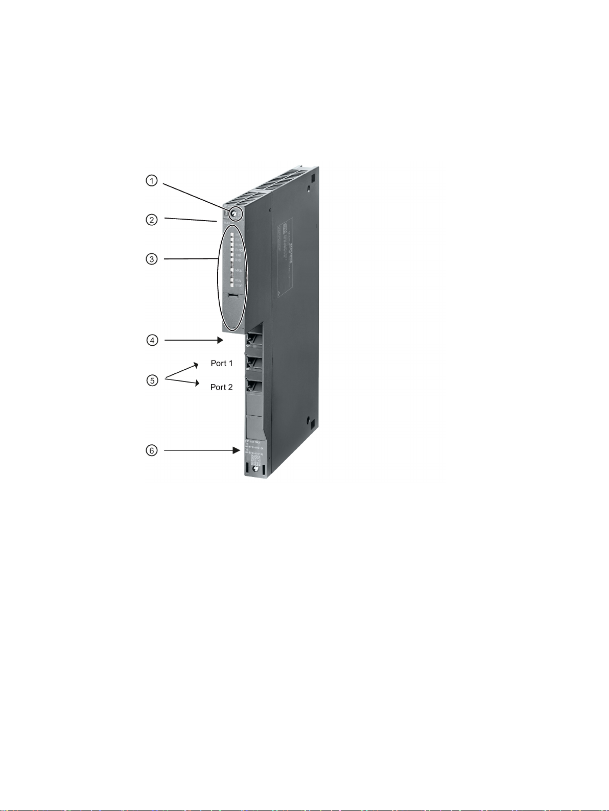
Legend:
①
X = placeholder for hardware product version
②
Firmware version
③
LEDs
④
Ethernet interface: Interface X1P1 with 1 x 8-pin RJ-45 jack
⑤
Designed for a redundant subnet
⑥
Label with MAC addresses
Validity and product names
RNA interface: Ports X2P1 / X2P2 with 2 x 8-pin RJ-45 jacks
Figure 1 CP 443-1 RNA
This description contains information on the following product
CP 443-1 RNA
Order number 6GK7 443-1RX00-0XE0
Hardware product version 1
CP 443-1 RNA
Manual, 03/2019, C79000-G8976-C299-04
3

Preface
Note
Names
•
•
New in this release
Replaced manual issue
Structure of the documentation
Current version of the manual and Information on the Internet
Firmware version V1.4.1
Communications processor for SIMATIC S7-400 / S7-400H
In this document, the term "CP" is used instead of the full product name.
The name STEP 7 is used for the configuration tool instead of the names STEP 7 V5.5
and STEP 7 Professional.
● New ATEX/IECEx approval
● Editorial revision
Replaced manual edition 7/2017
The documentation for this device consists of the following parts:
● Manual Part A: Configuration manual "Configuring and Commissioning S7CPs for
Industrial Ethernet", see references /1/ (Page 67).
● Manual Part B: Manual "CP 443-1 RNA" (this manual)
● Program blocks for SIMATIC NET S7 CPs - programming manual, see references /4/
(Page 68)
Contains the detailed description of the program blocks for the following services:
– Open communications services
– Access coordination with FETCH/WRITE
– Connection and system diagnostics
You will find the current version of this document and further information (e.g. FAQs) on
using the CP on the Internet at the following address:
Link: (https://support.industry.siemens.com/cs/ww/en/ps/15355)
Select the appropriate entry type in the filter settings.
CP 443-1 RNA
4 Manual, 03/2019, C79000-G8976-C299-04

Preface
CP documentation in the Manual Collection (order no. A5E00069051)
Compatibility with other modules - service and maintenance
Note
Read the information regarding extended functions and restrictions in section
modules used with CP 443
Address label: Unique MAC address preset for the CP
License conditions
Note
Open source software
Read the license conditions for open source software carefully before using the product. The
acceptance of the disclaimers of liability and warranty it contains is a clear precondition of
the use of open source software.
You will find the license condition
following file name:
OSS_CP44x1RNA_86.pdf
Firmware
The "SIMATIC NET Manual Collection" DVD contains the device manuals and descriptions
of all SIMATIC NET products current at the time it was created. It is updated at regular
intervals.
Replacing the
-1 RNA (Page 52) of this manual!
The CP is supplied with a total of 2 default MAC addresses with the following assignment:
● Ethernet interface
● RNA interface
The two MAC addresses of the Ethernet interface and the RNA interface are printed on the
housing.
If you configure a MAC address (ISO transport connections), we recommend that you use
the MAC address of the relevant interface printed on the module for module configuration!
● This ensures that you assign a unique MAC address in the subnet!
● If you replace a module, the MAC address of the predecessor is adopted when you load
the configuration data; configured ISO transport connections remain operable.
s on the same data medium as this manual under the
CP 443-1 RNA
Manual, 03/2019, C79000-G8976-C299-04
The firmware is signed and encrypted. This ensures that only firmware created by Siemens
can be downloaded to the device.
5

Preface
Security information
Recycling and disposal
SIMATIC NET glossary
Training, Service & Support
Siemens provides products and solutions with industrial security functions that support the
secure operation of plants, systems, machines and networks.
In order to protect plants, systems, machines and networks against cyber threats, it is
necessary to implement – and continuously maintain – a holistic, state-of-the-art industrial
security concept. Siemens’ products and solutions only form one element of such a concept.
Customer is responsible to prevent unauthorized access to its plants, systems, machines
and networks. Systems, machines and components should only be connected to the
enterprise network or the internet if and to the extent necessary and with appropriate security
measures (e.g. use of firewalls and network segmentation) in place.
Additionally, Siemens’ guidance on appropriate security measures should be taken into
account. For more information about industrial security, please visit
Link: (http://www.siemens.com/industrialsecurity)
Siemens’ products and solutions undergo continuous development to make them more
secure. Siemens strongly recommends to apply product updates as soon as available and to
always use the latest product versions. Use of product versions that are no longer supported,
and failure to apply latest updates may increase customer’s exposure to cyber threats.
To stay informed about product updates, subscribe to the Siemens Industrial Security RSS
Feed under
Link: (http://www.siemens.com/industrialsecurity).
The product is low in pollutants, can be recycled and meets the requirements of the WEEE
directive 2012/19/EU "Waste Electrical and Electronic Equipment".
Do not dispose of the product at public disposal sites. For environmentally friendly recycling
and the disposal of your old device contact a certified disposal company for electronic scrap
or your Siemens contact.
Keep to the local regulations.
You will find information on returning the product on the Internet pages of Siemens Industry
Online Support:
Link: (https://support.industry.siemens.com/cs/ww/en/view/109479891)
Explanations of many of the specialist terms used in this documentation can be found in the
SIMATIC NET glossary.
You will find the SIMATIC NET glossary on the Internet at the following address:
Link: (https://support.industry.siemens.com/cs/ww/en/view/50305045)
You will find information on training, service and support in the multilanguage document
"DC_support_99.pdf" on the Internet pages of Siemens Industry Online Support:
Link: (https://support.industry.siemens.com/cs/ww/en/view/38652101)
CP 443-1 RNA
6 Manual, 03/2019, C79000-G8976-C299-04

Table of contents
Preface ................................................................................................................................................... 3
1 Application and functions ........................................................................................................................ 9
2 Performance data ................................................................................................................................. 17
3 Requirements for use ............................................................................................................................ 23
4 LEDs..................................................................................................................................................... 27
5 Installation, connecting up, commissioning ............................................................................................ 31
6 Configuration and operation .................................................................................................................. 37
1.1 Properties of the CP .................................................................................................................. 9
1.2 Communication services ......................................................................................................... 10
1.3 Network topology with redundancy (PRP) .............................................................................. 11
1.4 Further services and characteristics of the CP ....................................................................... 15
2.1 General characteristic data ..................................................................................................... 17
2.2 Characteristics of S7 communication ..................................................................................... 17
2.3 SEND/RECEIVE interface ...................................................................................................... 18
2.3.1 Characteristic data .................................................................................................................. 18
2.3.2 Number of simultaneous SEND/RECEIVE calls ..................................................................... 19
2.4 Characteristics of open TCP/IP communication ..................................................................... 21
2.5 Characteristic data of TCP connections for HTTP .................................................................. 21
3.1 Configuration limits ................................................................................................................. 23
3.2 System environment ............................................................................................................... 23
3.3 Project engineering ................................................................................................................. 25
3.4 Programming .......................................................................................................................... 25
5.1 Important notes on using the device ....................................................................................... 31
5.1.1 Notices on use in hazardous areas ........................................................................................ 31
5.1.2 Notices on use in hazardous areas according to ATEX / IECEx ............................................ 32
5.1.3 Notices on use in hazardous areas according to UL HazLoc ................................................. 33
5.2 Installation - procedure ........................................................................................................... 33
5.3 Commissioning - procedure .................................................................................................... 34
5.4 Replacing a module without a programming device ............................................................... 35
5.5 Controlling the mode ............................................................................................................... 36
6.1 Security recommendations ..................................................................................................... 37
6.2 Switching over interfaces ........................................................................................................ 40
6.3 Memory reset / reset to factory defaults ................................................................................. 40
CP 443-1 RNA
Manual, 03/2019, C79000-G8976-C299-04
7

Table of contents
7 Upkeep and maintenance ..................................................................................................................... 51
8 Technical specifications ........................................................................................................................ 55
9 Approvals ............................................................................................................................................. 57
A PRP-compatible devices ....................................................................................................................... 63
B Documentation references .................................................................................................................... 67
Index .................................................................................................................................................... 71
6.4 Network settings..................................................................................................................... 42
6.4.1 Reserved MAC address ......................................................................................................... 42
6.4.2 Transmission properties of the Ethernet and RNA interfaces ............................................... 42
6.5 IP configuration ...................................................................................................................... 44
6.5.1 Setting the IP address ............................................................................................................ 44
6.5.2 Detecting duplicate IP addressing in the network .................................................................. 44
6.6 Time-of-day synchronization .................................................................................................. 45
6.7 Recommendation for use with a high communications load ................................................. 45
6.8 SNMP agent ........................................................................................................................... 46
6.9 Interface in the user program ................................................................................................. 48
6.9.1 Call interface for open communications services SEND/RECV ............................................ 48
6.9.2 Open TCP/IP communication ................................................................................................ 49
6.10 Ping: Permitted length of ICMP packets ................................................................................ 50
6.11 Communication in PRP mode ................................................................................................ 50
7.1 Loading new firmware ............................................................................................................ 51
7.2 Replacing the modules used with CP 443-1 RNA ................................................................. 52
B.1 Introduction to the documentation.......................................................................................... 67
B.2 On configuring, commissioning and using the CP ................................................................. 67
B.2.1 /1/ ........................................................................................................................................... 67
B.3 For configuration with STEP 7 / NCM S7 .............................................................................. 68
B.3.1 /2/ ........................................................................................................................................... 68
B.3.2 /3/ ........................................................................................................................................... 68
B.4 On programming (S7 CPs / OPC).......................................................................................... 68
B.4.1 /4/ ........................................................................................................................................... 68
B.4.2 /5/ ........................................................................................................................................... 68
B.4.3 /6/ ........................................................................................................................................... 69
B.4.4 /7/ ........................................................................................................................................... 69
B.4.5 /8/ ........................................................................................................................................... 69
B.4.6 /9/ ........................................................................................................................................... 69
B.5 S7 CPs On installing and commissioning the CP .................................................................. 70
B.5.1 /10/ ......................................................................................................................................... 70
B.6 On setting up and operating an Industrial Ethernet network ................................................. 70
B.6.1 /11/ ......................................................................................................................................... 70
CP 443-1 RNA
8 Manual, 03/2019, C79000-G8976-C299-04

1
1.1
Properties of the CP
Application
The CP has the following interfaces:
Note
Interfaces can only operated as alternatives
The Ethernet interface or the RNA interface can only be enabled as alternatives (one or the
other). Simultaneous use of both interfaces is not possible. These are activated during
configuration with STEP 7. Note further information in the section
(Page
The CP is intended for use in an S7400 or S7400H (faulttolerant) automation system. It
allows the S7400 / S7400H to be connected to Industrial Ethernet.
● Ethernet interface
The CP has a 100 Mbps Ethernet interface. The Ethernet interface can be used as an
alternative to the RNA interface. The Ethernet interface can, for example, be used to
connect to a PG/PC or to a higherlevel company network.
For special situations, each port can be set to a fixed mode manually using STEP 7, for
example 10 or 100 Mbps half duplex / full duplex.
● RNA interface
The RNA interface has 2 ports. These two ports are used as follows:
– PRP mode with both ports as a redundancy solution
– Port 1 as the only used port of the RNA interface with 100 Mbps full duplex (port 2 is
disabled)
The RNA interface only supports the "automatic setting" mode with 100 Mbps full duplex.
The communications partner must use the same settings.
Each port supports autocrossing and autonegotiation and is equipped with a combined
RXD/TXD / LINK dual LED for simple diagnostics.
Switching over interfaces
40)
CP 443-1 RNA
Manual, 03/2019, C79000-G8976-C299-04
9

Application and functions
①
Connection to port X1P1 of the Ethernet interface (ISO transport)
②
Connection of the RNA interface to a PRP network
③
Connection to port X2P1 of the RNA interface (ISO transport / ISO-on-TCP / TCP)
1.2
Communication services
S7 communication with the following functions:
Open communication services with the following functions:
1.1 Properties of the CP
Figure 1-1 CP 443-1 RNA - connection variants
Depending on the interface being used, the CP supports the following communications
services:
●
– PG functions;
– Operator monitoring and control functions;
– Data exchange over S7 connections.
●
– SEND/RECEIVE interface over ISO transport connections;
– SEND/RECEIVE interface over TCP connections, ISOonTCP and UDP connections;
With the SEND/RECEIVE interface via TCP connections, the CP supports the socket
interface to TCP/IP available on practically every end system.
UDP frame buffering on the CP can be disabled during configuration. When
necessary, this allows you to achieve a shorter reaction time between the arrival of a
UDP frame and its evaluation on the CPU.
– Multicast over UDP connection
The multicast mode is made possible by selecting a suitable IP address when
configuring connections.
– FETCH/WRITE services (server services; corresponding to S5 protocol) via ISO
transport connections, ISOonTCP connections and TCP connections;
Here, the SIMATIC S7400 with the CP is always the server (passive connection
establishment) while the fetch or write access (client function with active connection
CP 443-1 RNA
10 Manual, 03/2019, C79000-G8976-C299-04

Application and functions
Open TCP/IP communication
Interfaces used and communications services
Communications service
Ethernet interface
RNA interface
functions (ISO)
x x
- x
Data exchange over S7 connections (ISO)
x
x
Data exchange over S7 connections (TCP)
-
x
ISO transport connections
x
x
tions
- x
Multicast over UDP connection
-
x
FETCH/WRITE services (ISO)
x
x
FETCH/WRITE services (RFC, TCP)
-
x
nication
- x
Time of day
NTP mode and SIMATIC mode
-
x
via ISO x x
via TCP - x
1.3
Network topology with redundancy (PRP)
Redundant Network Access (RNA)
1.3 Network topology with redundancy (PRP)
establishment) is always initiated by a SIMATIC S5 or a device from another range /
PC.
– LOCK/UNLOCK with FETCH/WRITE services (CPUdependent; see section
Requirements for use (Page 23));
●
Open TCP/IP communication provides a program interface for the transfer of connectionoriented and connectionless services. The establishment and termination of connections
is initiated here only via the "dynamic" program interface.
STEP 7 provides a UDT for the connection parameter assignment as well as four FBs for
high-speed data exchange.
The CP supports communication via ISO-on-TCP connections for this interface.
The following table provides an overview of the services available at the interfaces.
S7 communication PG functions; operator control and monitoring
PG functions; operator control and monitoring
functions (ISO-on-TCP)
Open communications
services using
SEND/RECEIVE interface
Open TCP/IP commu-
H connections
TCP connections, ISOonTCP and UDP connec-
In Siemens Industry, Redundant Network Access (RNA) stands for devices and software that
support the redundancy protocol "Parallel Redundancy Protocol" (PRP). RNA allows the
connection of devices to redundant Ethernet network structures.
The product names of the RNA devices end with "RNA".
CP 443-1 RNA
Manual, 03/2019, C79000-G8976-C299-04
11

Application and functions
Parallel Redundancy Protocol (PRP)
Communication with PRP
1.3 Network topology with redundancy (PRP)
Some devices of the SCALANCE X-200RNA product line also support the redundancy
protocol "High-availability Seamless Redundancy" (HSR).
The Parallel Redundancy Protocol (PRP) is a redundancy protocol for Ethernet networks. It
is specified in IEC 62439-3.
The areas of application of PRP are distributed applications with high reliability demands that
depend on the high availability of the network. Compared with classic fault-tolerant networks,
bumpless path redundancy is possible with PRP.
PRP has the advantage that it uses parallel, separate networks made up of standard
network components. End devices that use this method are connected to both networks via
two ports of an interface of the device or via a SCALANCE X-200RNA or a RUGGEDCOM
RS950G. This means that data of the end device can be transferred at the same time via
both networks. If a transmission path is interrupted, the data reaches the communications
partner via the second parallel path.
If a network is interrupted, communication can be maintained with PRP via the second
network without any interruption. Reconfiguration times required with the other redundancy
protocols (e.g. MRP) do not therefore apply.
An end device with PRP capability can be connected to redundant networks by using the
PRP protocol. An end device that does not have PRP capability can be connected to a
redundant network via a SCALANCE X-200RNA or RUGGEDCOM RS950G that does have
PRP capability. This means that PRP can also be used by end devices without PRP
capability.
Devices with PRP capability are located in two independent networks with the same MAC
and IP address.
PRP is only possible when two end devices are connected via two independent networks
(LAN A and LAN B).
Each end device is represented in both networks LAN A and LAN B with the same MAC and
IP address.
CP 443-1 RNA
12 Manual, 03/2019, C79000-G8976-C299-04

Application and functions
Send
Received
Connecting up and cabling
Note
Cabling
Make sure that all the PRP ports of the nodes and the SCALANCE X204RNA /
RUGGEDCOM RS950G on LAN A and LAN B are connected correctly. A frame with the
identifier "LAN A" must be received at the corresponding port.
How is a redundant PRP network set up?
1.3 Network topology with redundancy (PRP)
PRP communication is handled using the following mechanisms:
●
An end device with PRP capability duplicates each frame to be sent on the PRP
interface. The two duplicates are sent via the 2 ports of the PRP interface via the two
separate networks LAN A and LAN B to the communications partner.
If the end device does not have PRP capability, the frame to be sent is duplicated by an
X-200RNA to which the end device is connected and sent via LAN A and LAN B to the
communications partner.
●
The two duplicates are received by an end device with PRP capability via LAN A and
LAN B on the two ports of the PRP interface.
If the end device does not have PRP capability, the receiving end device must be
preceded by an X-200RNA. The X-200RNA forwards the first frame to arrive to the
addressee. The second frame is discarded ((N-1) redundancy).
Each frame duplicate sent using the PRP mechanisms is given in identifier that specifies
whether it is sent via LAN A or LAN B.
The PRP ports of SIMATIC NET devices have the following identifiers. The CP ports are the
ports of the interface with PRP capability.
● Ports for connection to LAN A
– CPs: X2/P1
– SCALANCE X204RNA: PRP A
● Ports for connection to LAN B
– CPs: X2/P2
– SCALANCE X204RNA: PRP B
A network topology in which the Parallel Redundancy Protocol is used (PRP network)
consists of two separate Ethernet subnets. The structure of the two subnets does not need
to be identical.
CP 443-1 RNA
Manual, 03/2019, C79000-G8976-C299-04
13
Application and functions
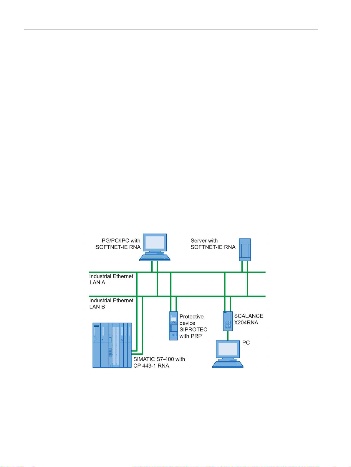
Example of a configuration for a PRP network
1.3 Network topology with redundancy (PRP)
A PRP network can be set up both with end devices with PRP capability as well as with
standard components. The following devices can be used:
● End devices with PRP capability (Double Attached Nodes PRP, Double Attached Node
implementing PRP, DANP), for example:
– CP 443-1 RNA
– PC with SOFTNET-IE RNA
– SIPROTEC protective devices with PRP capability
● Standard components (Singly Attached Nodes, SAN)
Standard components without PRP functionality, for example, can be connected to a PRP
network via SCALANCE X-200RNA or RuggedCom RS950G.
SANs can, however, also be connected to a PRP network without supporting the PRP
functionality.
All devices that are intended to use the PRP function in redundant networks must be able to
process frames with length of up to 1532 bytes (oversize frames). If this function is not
supported, data may be lost.
The following figure shows the options for connecting devices in a network topology in which
the Parallel Redundancy Protocol (PRP) is used.
Figure 1-2 Example of the configuration of a network topology with PRP
CP 443-1 RNA
14 Manual, 03/2019, C79000-G8976-C299-04

Application and functions
1.4
Further services and characteristics of the CP
Timeofday synchronization over the RNA interface using the following configurable
modes:
Addressable with the factoryset MAC address
SNMP agent on the RNA interface
Module access protection
IP access protection on the RNA interface (IPACL)
Web diagnostics on the RNA interface
Diagnostics buffer extract request
1.4 Further services and characteristics of the CP
●
– SIMATIC mode
or
– NTP mode (NTP: Network Time Protocol)
●
To assign the IP address to a new CP (direct from the factory), it can be accessed using
the preset MAC address on port X2P1 of the RNA interface. Online address assignment
is made in STEP 7.
The CP receives MMS timeofday messages and synchronizes its local time.
You can choose whether or not the time of day is forwarded. You can also decide on
the direction in which it is forwarded.
The CP sends timeofday queries at regular intervals to an NTP server and
synchronizes its local time of day.
The time can also be forwarded automatically to the CPU modules in the S7 station
allowing the time to be synchronized in the entire S7 station.
●
The CP supports data queries over SNMP in version V1 (Simple Network Management
Protocol). It delivers the content of certain MIB objects according to the MIB II standard
(RFC 1213), PRP-MIB IEC62439 (IEC-62439-3-MIB) and Automation MIB.
●
To protect the module from accidental or unauthorized access, protection can be
configured at various levels.
●
Using IP access protection gives you the opportunity of restricting communication over
the CP of the local S7 station to partners with specific IP addresses.
●
With the aid of Web diagnostics, you can read out the diagnostics data from a station
connected via the CP to a PG/PC with a Web browser.
The Web pages contain the following information:
– Module and status information
●
With the aid of a Web browser, the CP supports the option of obtaining an extract of the
diagnostics buffer containing the most recent diagnostics events of the CPUs and CPs
located in the same S7 station as the CP.
CP 443-1 RNA
Manual, 03/2019, C79000-G8976-C299-04
15

Application and functions
Connection diagnostics with the AG_CNTEX program block
S5/S7 addressing mode
Detecting IP double addressing in the network on the RNA interface
Support in the fault-tolerant system (H system)
1.4 Further services and characteristics of the CP
●
With the AG_CNTEX program block, you can diagnose connections.
– When necessary, you can activate or deactivate connections or initiate
reestablishment of a connection.
– You can check the reachability of the connection partners using the PING function (on
the RNA interface).
– You can find out which connection types are set up on the RNA interface for the
SEND / RECEIVE function.
●
The addressing mode can be configured for FETCH/WRITE access as the S7 or S5
addressing mode (S7 addressing mode only for data blocks / DBs).
●
To save you timeconsuming troubleshooting in the network, the CP detects double
addressing in the network.
For more detailed information, see section Detecting duplicate IP addressing in the
network (Page 44)
●
S7 communication is supported in the H system with the following protocols:
– Ethernet interface
ISO transport
– RNA interface
ISO transport and ISO-on-TCP (RFC1006)
CP 443-1 RNA
16 Manual, 03/2019, C79000-G8976-C299-04

2
2.1
General characteristic data
Characteristic
Explanation / values
Example
2.2
Characteristics of S7 communication
Characteristic
Explanation / values
of those max. 62 H connections
Total number of connections on Industrial Ethernet 128
The value applies to the total number of connections of the
following types:
• S7 connections
• SEND/RECEIVE connections
You can, for example, operate the following combination of connections:
● 62 S7 connections or 62 H connections
● 30 ISO-on-TCP connections
● 10 TCP connections
● 10 UDP connections
● 8 ISO transport connections
S7 communication provides data transfer via the ISO Transport or ISO-on-TCP protocols.
Total number of S7 connections on Industrial
Ethernet
LAN interface - data field length generated by CP
per protocol data unit
• sending
• receiving
• Number of PG connections
• Number of OP connections
128 max.,
480 bytes / PDU
480 bytes / PDU
2 max.
30 max.
CP 443-1 RNA
Manual, 03/2019, C79000-G8976-C299-04
17

Performance data
Note
Effects of connections in the SPEED SEND/RECV mode
Note the effects of connections on the SEND/RECEIVE interface that are used in the
SPEED SEND/RECEIVE mode.
The maximum configuration limits of S7 communic
connection using the SPEED SEND/RECV mode.
2.3
SEND/RECEIVE interface
2.3.1
Characteristic data
The following characteristics are important:
Characteristic
Explanation / values
cannot
by the sender (approximately 150200 messages per second).
program blocks.
2.3 SEND/RECEIVE interface
ation are reduced by each configured
The SEND/RECEIVE interface provides access to communication over TCP, ISOonTCP,
ISO transport and UDP connections.
Number of SEND/RECEIVE connections
Number of SEND/RECV connections in
SPEED SEND/RECV mode
Maximum data length for AG_SEND and
AG_RECV program blocks
• TCP connections: 1...64
• ISO-on-TCP connections: 1...64
• ISO transport connections: 1...64
• Total number of UDP connections (specified and free) that can be
• Max. number of connections in total:
Refer to the example in section 5.1 (Page 17)
Notes:
•
The number depends on the CPU type being used.
• Per CPU 412/414 maximum 30
• Per CPU 416/417 maximum 62
AG_SEND and AG_RECV were shipped with other CPs of the S7-400
family and allowed the transfer of user data with a length of 1 to 240
bytes. The version of the CP described here continues to support these
1)
configured: 1 to 64 (of those up to 48 in multicast mode)
(ISO transport and ISOonTCP
+ TCP + UDP) <= 64
1)
Avoid overload at receiving end
The flow control on TCP connections
load of the recipient. You should therefore make sure that the processing capabilities of a receiving CP are not permanently exceeded
control permanent over-
CP 443-1 RNA
18 Manual, 03/2019, C79000-G8976-C299-04

Performance data
Characteristic
Explanation / values
2. UDP: 1 to 1452 bytes
Restrictions for UDP
2.3.2
Number of simultaneous SEND/RECEIVE calls
2.3 SEND/RECEIVE interface
Maximum data length for AG_LSEND and
AG_LRECV program blocks
Maximum data length for
AG_SSEND and AG_SRECV program blocks
LAN interface max. data field length generated by CP per protocol data unit
● Transfer is not acknowledged.
AG_LSEND and AG_LRECV allow the transfer of user data with the following lengths:
1. ISO-on-TCP, TCP, ISO transport: 1 to 8192 bytes
2. UDP: 1 to 2048 bytes
AG_SSEND and AG_SRECV allow the transfer of user data with the
following lengths:
1. ISO-on-TCP, TCP, ISO transport: 1 to 1452 bytes
• sending
ISO transport, ISOonTCP, TCP:
– 400 bytes / TPDU with AG_SEND / AG_LSEND
– 1452 bytes / TPDU with AG_SSEND
• receiving
– ISO transport: 512 bytes / TPDU
– ISO-on-TCP: 1452 bytes / TPDU
– TCP: 1452 bytes / TPDU
The transmission of UDP frames is unconfirmed, in other words the loss of messages is
not detected or displayed by the send blocks (AG_SEND or AG_LSEND).
● No receipt of UDP broadcast
To avoid overload due to high broadcast load, the CP does not allow reception of UDP
broadcasts.
As an alternative, use the multicast function over a UDP connection. This allows you to
register the CP as a node in a multicast group.
● UDP frame buffering
Length of the frame buffer with buffering enabled:
2 KB
Note:
Following a buffer overflow, newly arriving frames are discarded.
The number of SEND/RECEIVE calls that can be used at the same time is limited both by
the CPU and by the CP.
If the maximum number of simultaneous SEND/RECEIVE calls is exceeded, the value
8302H (no receive resources) is indicated in the STATUS of the surplus SEND functions.
This can, for example, happen when too many SEND/RECEIVE calls are sent at the same
time in OB1.
CP 443-1 RNA
Manual, 03/2019, C79000-G8976-C299-04
19

Performance data
Limitation by the CPU
Limitation by the CP
Number of simultaneous
SEND calls
0 1 2
3, 4 5 6 7
8, 9 10
11
12
ous FC60s per CPU 412/414
2.3 SEND/RECEIVE interface
In productive operation, the number of SEND/RECEIVE calls that can be used at one time
depends on the CPU resources being used. Note the information on the available CPU
resources in section System environment (Page 23).
The following CPU resources are required:
● Per SEND job short (AG_SEND) or long (AG_LSEND): 1 resource
● Per RECEIVE job short (AG_RECV): 1 resource
● Per RECEIVE job long (AG_LRECV): 2 resources
● Per SPEED SEND/RECV job (AG_SSEND, AG_SRECV): 0 resources
A maximum of 64 SEND/RECEIVE connections can be operated by the CP.
At an assignment of 1 CP per CPU, the maximum number of SEND/RECEIVE calls that can
be used at one time is limited as follows:
*)
● SEND calls short (AG_SEND) or long (AG_LSEND): max. 32
*)
● RECEIVE calls short (AG_RECV): max. 64
● RECEIVE calls long (AG_LRECV): variable
*)
The higher values apply to the CPU 416 and CPU 417.
**)
The lower values apply to the CPU 412 and CPU 414.
***)
The number of AG_LRECV program blocks that can be used at the same time depends
/ 24
***)
**)
per CPU
on the number of SEND calls active at the same time (see tables below).
/ 12
**)
per CPU
Table 2- 1 Dependency of the maximum number of RECEIVE calls long (AG_LRECV FC60) used at the same time on
the number of SEND calls (CPU 412/414)
Max. number of simultane-
CP 443-1 RNA
20 Manual, 03/2019, C79000-G8976-C299-04
19 18 17 16 15 14 13 12 11 10 9

Performance data
Number of simultaneous
SEND calls
0 1 2
3, 4 5 6 7
8, 9 10
11
12
13,
14
15
16
CPU 416/417/41x-H
Number of simultaneous
SEND calls
17 18,
19
20 21 22 23,
24
25 26 27 28,
29
30 31 32
CPU 416/417/41x-H
2.4
Characteristics of open TCP/IP communication
Characteristic
Explanation / values
trial Ethernet
Max. data length
1452 bytes
2.5
Characteristic data of TCP connections for HTTP
Characteristic data of TCP connections for HTTP
2.4 Characteristics of open TCP/IP communication
Table 2- 2 Dependency of the maximum number of RECEIVE calls long (AG_LRECV FC60) used at the same time on
the number of SEND calls (CPU 416/417)
Max. number of simultaneous FC60s per
Max. number of simultaneous FC60s per
51 50 49 48 47 46 45 44 43 42 41 40 39 38
37 36 35 34 33 32 31 30 29 28 27 26 25
The maximum number of SPEED SEND/RECEIVE calls that can be used simultaneously
(FC53, FC63) depends only on the CPU (see above).
Open TCP/IP communication provides a program interface for the transfer of connectionoriented and connectionless services. The establishment and termination of connections is
initiated here only via the "dynamic" program interface.
The CP supports communication via ISO-on-TCP connections for this interface.
Table 2- 3 Open TCP/IP communication
Number of dynamically generated connections over Indus-
For HTTP access, up to 4 CP-internal TCP connections are available. When necessary,
these TCP connections are used by one or more Web browsers to display data of the CP.
CP-internal TCP connections do not affect the configuration limits of the configured TCP
connection resources.
• ISO-on-TCP connections: 1...64
CP 443-1 RNA
Manual, 03/2019, C79000-G8976-C299-04
21

Performance data
2.5 Characteristic data of TCP connections for HTTP
CP 443-1 RNA
22 Manual, 03/2019, C79000-G8976-C299-04
 Loading...