

SIMATIC NET S7-1200,SIMATIC NET CP 1243-1 DNP3,SIMATIC NET CP 1243-1 IEC
Table of contents
 Loading...
Siemens SIMATIC NET S7-1200,SIMATIC NET CP 1243-1 DNP3,SIMATIC NET CP 1243-1 IEC Operating Instructions Manual

CP 1243-1 DNP3, CP 1243-1 IEC
___________________
___________________
___________________
___________________
___________________
___________________
___________________
___________________
___________________
___________________
___________________
SIMATIC NET
S7-1200 - Telecontrol
CP 1243-1 DNP3,
CP 1243-1 IEC
Operating Instructions
02/2014
C79000
Preface
Application and properties
1
Requirements for use
2
LEDs and connectors
3
Installation, connecting up,
commissioning
4
Configuration and operation
5
Diagnostics and upkeep
6
Technical specifications
7
Approvals
A
Dimension drawings
B
Documentation references
C
-G8976-C312-02

Siemens AG
Industry Sector
Postfach 48 48
90026 NÜRNBERG
GERMANY
C79000-G8976-C312-02
Ⓟ
Copyright © Siemens AG 2013 - 2014.
All rights reserved
Warning notice system
DANGER
indicates that death or severe personal injury will result if proper precautions are not taken.
WARNING
indicates that death or severe personal injury may result if proper precautions are not taken.
CAUTION
indicates that minor personal injury can result if proper precautions are not taken.
NOTICE
indicates that property damage can result if proper precautions are not taken.
Qualified Personnel
personnel qualified
Proper use of Siemens products
WARNING
Siemens products may only be used for the applications described in the catalog and in the relevant technical
maintenance are required to ensure that the products operate safely and without any problems. The permissible
ambient conditions must be complied with. The information in the relevant documentation must be observed.
Trademarks
Disclaimer of Liability
Legal information
This manual contains notices you have to observe in order to ensure your personal safety, as well as to prevent
damage to property. The notices referring to your personal safety are highlighted in the manual by a safety alert
symbol, notices referring only to property damage have no safety alert symbol. These notices shown below are
graded according to the degree of danger.
If more than one degree of danger is present, the warning notice representing the highest degree of danger will
be used. A notice warning of injury to persons with a safety alert symbol may also include a warning relating to
property damage.
The product/system described in this documentation may be operated only by
task in accordance with the relevant documentation, in particular its warning notices and safety instructions.
Qualified personnel are those who, based on their training and experience, are capable of identifying risks and
avoiding potential hazards when working with these products/systems.
for the specific
Note the following:
documentation. If products and components from other manufacturers are used, these must be recommended
or approved by Siemens. Proper transport, storage, installation, assembly, commissioning, operation and
All names identified by ® are registered trademarks of Siemens AG. The remaining trademarks in this publication
may be trademarks whose use by third parties for their own purposes could violate the rights of the owner.
We have reviewed the contents of this publication to ensure consistency with the hardware and software
described. Since variance cannot be precluded entirely, we cannot guarantee full consistency. However, the
information in this publication is reviewed regularly and any necessary corrections are included in subsequent
editions.
02/2014 Technical data subject to change
Preface
Validity of this manual
CP 1243-1 DNP3
CP 1243-1 IEC
This document contains information on the following telecontrol products:
●
Article number6GK7 243-1JX30-0XE0
Hardware product version 1
Firmware version V1.1
The CP 1243-1 DNP3 is the communications processor for connecting SIMATIC S7-1200
to control centers using the DNP3 protocol.
●
Article number6GK7 243-1PX30-0XE0
Hardware product version 1
Firmware version V1.1
The CP 1243-1 IEC is the communications processor for connecting SIMATIC S7-1200 to
control centers using the IEC 60870-5 protocol.
CP 1243-1 DNP3, CP 1243-1 IEC
Operating Instructions, 02/2014, C79000-G8976-C312-02
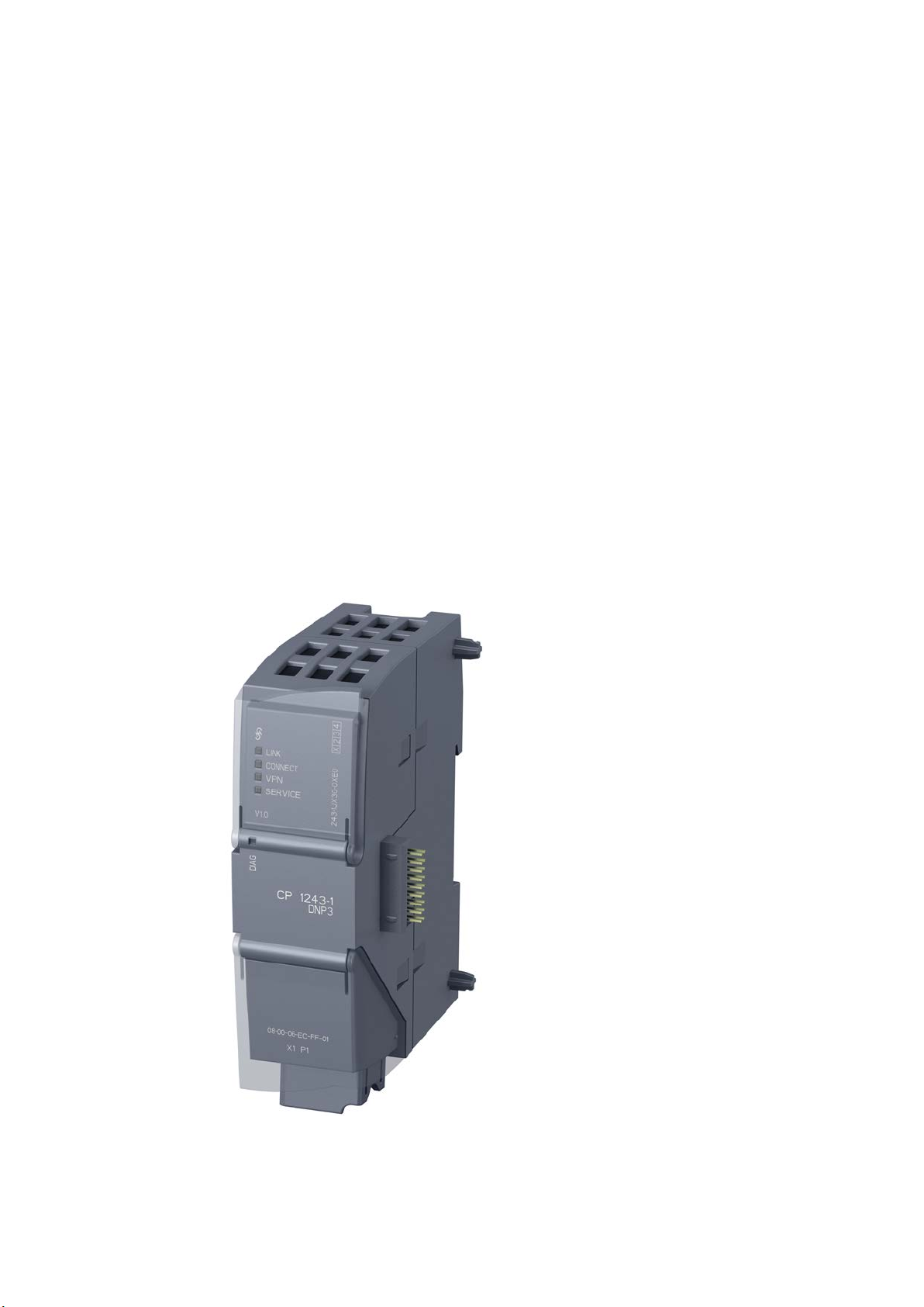
Figure 1 CP 1243-1 DNP3
3

Preface
Product names and abbreviations
CP
DNP3-CP
IEC-CP
Purpose of the manual
New in this issue
The CP 1243-1 IEC has the same outer design as the CP 1243-1 DNP3 apart from the
inscriptions for the product name, article number, firmware version and possibly hardware
product version.
At the top right behind the hinged cover of the module housing, you will see the hardware
product version printed as a placeholder "X" after the article number. If the printed text is, for
example, "X 2 3 4", "X" would be the placeholder for hardware product version 1.
In this document, you will find the following designations used for the product being
described here:
●
Simplified naming of the two following products:
– CP 1243-1 DNP3
– CP 1243-1 IEC
This short form is used in this manual if the property being described in the particular
context applies to both modules.
●
Short form for the CP 1243-1 DNP3 (6GK7 243-1JX30-0XE0)
●
Short form for the CP 1243-1 IEC (6GK7 243-1PX30-0XE0)
This manual describes the properties of both these modules and supports you when
installing and commissioning them.
The required configuration steps are described as an overview and there are explanations of
the relationship between firmware functions and configuration.
You will also find information about the diagnostics options of the device.
● Inclusion of the CP 1243-1 IEC
● New firmware version of the DNP3 CP with bugs fixed
Make sure that the DNP3 CP with firmware version V1.0 or V1.1 is compatible with the
firmware of the CPU, refer to the section Hardware requirements (Page 17).
● Editorial revision
As a supplement to the STEP 7 information system, note the information on the functions
and parameters in the section Notes on configuring individual functions (Page 42).
CP 1243-1 DNP3, CP 1243-1 IEC
4 Operating Instructions, 02/2014, C79000-G8976-C312-02

Preface
Replaced documentation
Current manual release on the Internet
Required experience
Requirements for use of the module
Sources of information and other documentation
SIMATIC NET glossary
This manual replaces the manual release 07/2013.
You will also find the current version of this manual on the Internet pages of Siemens
Industry Online Support in the directory of the relevant CP. This is located below the
directory with the following entry ID:
16514597 (http://support.automation.siemens.com/WW/view/en/16514597)
To install, commission and operate the CP, you require experience in the following areas:
● Automation engineering
● Setting up the SIMATIC S7-1200
● SIMATIC STEP 7 Basic / Professional
● DNP3 protocol or protocol according to IEC 60870-5
You will find the requirements for using the module in the section Hardware requirements
(Page 17).
You will find an overview of further reading and references in the Appendix of this manual.
Explanations of many of the specialist terms used in this documentation can be found in the
SIMATIC NET glossary.
You will find the SIMATIC NET glossary here:
● SIMATIC NET Manual Collection or product DVD
The DVD ships with certain SIMATIC NET products.
● On the Internet under the following entry ID:
50305045 (http://support.automation.siemens.com/WW/view/en/50305045)
CP 1243-1 DNP3, CP 1243-1 IEC
Operating Instructions, 02/2014, C79000-G8976-C312-02
5

Preface
License conditions
Note
Open source software
Read the license conditions for open source software carefu
acceptance of the disclaimers of liability and warranty it contains is a clear precondition of
the use of open source software.
Security information
Training, Service & Support
lly before using the product. The
You will find license conditions in the following documents on the supplied data medium:
● DOC_OSS-S7CMCP_74.pdf
● DOC_OSS-CP1243-1DNP3-IEC_76.pdf
Siemens provides automation and drive products with industrial security functions that
support the secure operation of plants or machines. They are an important component in a
holistic industrial security concept. With this in mind, our products undergo continuous
development. We therefore recommend that you keep yourself informed with respect to our
product updates. Please find further information and newsletters on this subject at:
http://support.automation.siemens.com.
To ensure the secure operation of a plant or machine it is also necessary to take suitable
preventive action (e.g. cell protection concept) and to integrate the automation and drive
components into a state-of-the-art holistic industrial security concept for the entire plant or
machine. Any third-party products that may be in use must also be taken into account.
Please find further information at: http://www.siemens.com/industrialsecurity
You will find information on Training, Service & Support in the multi--language document
"DC_support_99.pdf" on the data medium supplied with the documentation.
CP 1243-1 DNP3, CP 1243-1 IEC
6 Operating Instructions, 02/2014, C79000-G8976-C312-02

Table of contents
Preface ................................................................................................................................................... 3
1 Application and properties ....................................................................................................................... 9
2 Requirements for use ............................................................................................................................ 17
3 LEDs and connectors ............................................................................................................................ 19
4 Installation, connecting up, commissioning ............................................................................................ 25
5 Configuration and operation .................................................................................................................. 31
1.1 Communications services .............................................................................................................. 9
1.2 Other services and properties ...................................................................................................... 10
1.3 Configuration limits and performance data .................................................................................. 12
1.4 DNP3 device profile ..................................................................................................................... 13
1.5 Configuration examples ............................................................................................................... 14
1.5.1 Configuration with 1 subnet ......................................................................................................... 14
1.5.2 Configuration with connections over the Internet ......................................................................... 14
1.5.3 Configuration with a redundant control center ............................................................................. 16
2.1 Hardware requirements ............................................................................................................... 17
2.2 Software requirements ................................................................................................................. 18
3.1 Opening the covers of the housing .............................................................................................. 19
3.2 LEDs ............................................................................................................................................ 20
3.3 Electrical connections .................................................................................................................. 23
3.3.1 Power supply ................................................................................................................................ 23
3.3.2 Ethernet interface X1P1 ............................................................................................................... 23
4.1 Important notes on using the device ............................................................................................ 25
4.1.1 Notices on use in hazardous areas.............................................................................................. 25
4.1.2 Notices regarding use in hazardous areas according to ATEX ................................................... 26
4.1.3 Notices regarding use in hazardous areas according to UL HazLoc ........................................... 27
4.2 Installation .................................................................................................................................... 27
4.3 Installing, connecting up and commissioning .............................................................................. 29
5.1 Note on operation ........................................................................................................................ 31
5.2 Addressing and network configuration ......................................................................................... 31
5.3 Configuration in STEP 7 .............................................................................................................. 32
5.4 Configuring datapoints and messages (e-mails) ......................................................................... 33
5.5 Datapoint types ............................................................................................................................ 35
5.6 CPU scan cycle ............................................................................................................................ 38
5.7 Types of transmission, event classes, triggers ............................................................................ 39
CP 1243-1 DNP3, CP 1243-1 IEC
Operating Instructions, 02/2014, C79000-G8976-C312-02
7

Table of contents
6 Diagnostics and upkeep ........................................................................................................................ 59
7 Technical specifications ........................................................................................................................ 63
A Approvals ............................................................................................................................................. 65
B Dimension drawings .............................................................................................................................. 69
C Documentation references .................................................................................................................... 71
Index .................................................................................................................................................... 73
5.8 Notes on configuring individual functions .................................................................................... 42
5.8.1 Communication types and SNMP ............................................................................................... 42
5.8.2 Ethernet interface (X1) > Advanced options ............................................................................... 43
5.8.3 Partner stations ........................................................................................................................... 46
5.8.4 Partner stations > Security options (DNP3) ................................................................................ 48
5.8.5 Communication with the CPU ..................................................................................................... 49
5.8.6 Data point configuration .............................................................................................................. 50
5.8.6.1 "General" parameter group ......................................................................................................... 50
5.8.6.2 Threshold value trigger and Analog value preprocessing ........................................................... 50
5.8.6.3 "Analog value preprocessing" parameter group ......................................................................... 51
5.8.6.4 Analog value preprocessing ........................................................................................................ 51
5.8.6.5 Threshold value trigger ............................................................................................................... 54
5.8.7 Configuring messages ................................................................................................................ 55
6.1 Diagnostics options ..................................................................................................................... 59
6.2 Downloading firmware ................................................................................................................. 59
6.3 Module replacement .................................................................................................................... 62
CP 1243-1 DNP3, CP 1243-1 IEC
8 Operating Instructions, 02/2014, C79000-G8976-C312-02

1
1.1
Communications services
Communications services
DNP3-CP
DNP3 protocol
S7 communication and PG/OP communication with the following functions:
IEC-CP
Protocol IEC 60870-5
S7 communication and PG/OP communication with the following functions:
Status IDs of data points
The following communications services are supported:
●
Communication is based on the DNP3 SPECIFICATION Version 2.x (2007/2009).
The CP is a communications processor of the SIMATIC S7-1200 for system connection to
control centers using the DNP3 protocol for telecontrol applications.
An S7-1200 with CP 1243-1 DNP3 operates as a DNP3 station (Outstation).
The CP supports the implementation level 1 - 4 (DNP3 Application Layer protocol Level).
You will find a description of the other functions in the section Partner stations (Page 46).
●
– PUT/GET as client and server for data exchange with remote stations (S7-
300/400/1200/1500)
– PG functions
– Operator control and monitoring functions (HMI)
●
Communication is based on the specification IEC 60870-5 Part 1 - 5 (1990 - 1995) and
part 104 (2000).
The CP is a communications processor of the SIMATIC S7-1200 for system connection to
control centers using the IEC 60870-5 protocol for telecontrol applications.
An S7-1200 with CP 1243-1 IEC operates as a substation (slave).
●
– PUT/GET as client and server for data exchange with remote stations (S7-
300/400/1200/1500)
– PG functions
– Operator control and monitoring functions (HMI)
The status IDs listed in the following tables are transferred for each data point in each frame
in 1 byte.
The meaning relates to the bit status in the last row of each table.
CP 1243-1 DNP3, CP 1243-1 IEC
Operating Instructions, 02/2014, C79000-G8976-C312-02
9

Application and properties
Bit
7 6 5 4 3 2 1
0
Flag name
FORCED
NUITY
RANGE
Meaning
value
Bit status
(always 0)
(always 0)
(always 0)
1 1 1 1 1
Bit
7 6 5 4 3 2 1
0
Flag name
substituted
carry
overflow
not topical
invalid
Meaning
value
Bit status
(always 0)
(always 0)
1
(always 0)
1 1 1
0
1.2
Other services and properties
Other services and properties
Data point configuration
Security functions (DNP3 only)
1.2 Other services and properties
Table 1- 1 DNP3: Byte assignment of the status byte for DNP3 data points
- - - LOCAL_-
- - - Local
operator
control
Table 1- 2 IEC: Byte assignment of the status byte for IEC data points
- - SB
- - Substitute
value
- CY
- Counted
DISCONTI-
Counted
value
overflow
before
reading the
value
overflow
before
reading the
OVER_-
Value
range
exceeded,
analog
value
OV
Value
range
exceeded,
analog
value
RESTART ONLINE
Value not
updated
after start
NT
Value not
updated
Value is
invalid
IV
Value is
invalid
●
Due to the data point configuration in STEP 7, programming program blocks in order to
transfer the process data is unnecessary. The individual data points are processed oneto-one in the control system.
●
The DNP3 CP can use the security functions specified in the DNP3 protocol and
therefore secure communication in the DNP3 network, including the following:
– Secure authentication (SA) of the communications partner
The DNP3 CP checks whether the communications partner has the right to access the
DNP3 CP.
Formation of the Message Authentication Code (MAC) using symmetrical (pre-shared
key, PSK) or asymmetrical cryptography (public/private keys)
Use of IPsec for transferring the key
– Logging of security events: Successful and failed authentication, key exchange,
statistical counters
You enable the security functions in the STEP 7 configuration with the required options.
CP 1243-1 DNP3, CP 1243-1 IEC
10 Operating Instructions, 02/2014, C79000-G8976-C312-02

Application and properties
IP configuration - IPv4 and IPv6
Time-of-day synchronization over Industrial Ethernet
Redundancy
Storage of events
Data transfer is on request or triggered
Messages / e-mail
Analog value processing
1.2 Other services and properties
●
The essential features of IP configuration for the CP:
– The CP supports IP addresses according to IPv4 and IPv6.
– An IPv6 address can be used in addition to an IPv4 address.
– Address assignment:
The IP address, the subnet mask and the address of a gateway can be set manually
in the configuration.
As an alternative, the IP address can be obtained from a DHCP server or by other
means outside the configuration.
●
The CP can the have its local time of day synchronized by the partner (master) as UTC
time.
The time of day can be read from the CPU. The mechanisms are described in the STEP
7 information system.
For information on the format of the time stamp, refer to the section Datapoint types
(Page 35).
●
The CP can communicate with a redundant control system (master).
●
The CP can store events of different classes and transfer them together to the master.
●
The sending of data to the master can be triggered in two ways:
– At the request of the master
– Triggered by various selectable criteria
●
With configured events in the process image of the CPU, the CP can send messages as
e-mails. The data of the events to be sent by e-mail are configured using PLC tags.
●
Analog values can be preprocessed on the CP according to various methods.
CP 1243-1 DNP3, CP 1243-1 IEC
Operating Instructions, 02/2014, C79000-G8976-C312-02
11

Application and properties
Online functions
SNMP
1.3
Configuration limits and performance data
Number of CMs/CPs per station
Connection resources
TCP connections to masters (DNP3 or IEC)
Online functions / TeleService
S7 connections
PG/OP connections
1.3 Configuration limits and performance data
●
From an engineering station (ES) on which STEP 7 is installed, you can use the online
functions of STEP 7 via the CP to access the S7-1200 CPU if the station is located in the
same IP subnet. The following online functions are available:
– Downloading project or program data from the STEP 7 project to the station
– Querying diagnostics data on the station
– Downloading firmware files to the CP
For a remote station located in a different IP subnet or that can be reached via the
Internet, these functions can only be used if the ES is connected to the station via a VPN
tunnel (for example via a SCALANCE S).
●
As an SNMP agent, the CP supports data queries using SNMP (Simple Network
Management Protocol) in version V1.
For more detailed information, refer to section Communication types and SNMP
(Page 42).
In each S7-1200 station, up to three CMs/CPs can be plugged in and configured; this means
a maximum of three identical CP 1243-1 DNP3 or three identical CP 1243-1 IEC modules.
●
The CP can establish connections to up to 4 masters. These can be single or redundant
masters.
In the case of 4 redundant masters, this would be 8 physical devices addressed using
different IP addresses.
●
1 connection resource is reserved for online functions / TeleService.
●
8 connection resources for S7 connections (PUT/GET)
●
– 1 connection resource for PG connections
– 3 connection resources for OP connections
CP 1243-1 DNP3, CP 1243-1 IEC
12 Operating Instructions, 02/2014, C79000-G8976-C312-02

Application and properties
Number of data points for the data point configuration
User data
Frame memory (send buffer)
Messages / e-mail
1.4
DNP3 device profile
Detailed information on DNP3 attributes in the DNP3 device profile
1.4 DNP3 device profile
The maximum number of configurable data points is 200.
The data to be transferred by the CP is assigned to various data points in the STEP 7
configuration. The size of the user data per data point depends on the data type of the
relevant data point.
With the DNP3 CP, contiguous memory areas can be transferred up to a size of 64 bytes
using data point types of the object groups 110 (Octet String) and 111 (Octet String Event).
You will find details in the information system of STEP 7 and in the section Datapoint types
(Page 35).
The CP has a frame memory (send buffer) for data points configured as an event.
The send buffer has a maximum size of 64000 events divided into equal parts for all
configured communications partners. The size of the frame memory can be set in STEP 7,
refer to the section Communication with the CPU (Page 49).
You will find details of how the send buffer works (storing and sending events) as well as the
options for transferring data in the section Types of transmission, event classes, triggers
(Page 39).
Up to 10 messages can be configured in STEP 7 and sent as e-mails.
You will find a detailed overview of the attributes and properties specified in the DNP3
protocol and supported by the CP in the DNP3 device profile.
You will find the DNP3 device profile of the CP 1243-1 DNP3 on the Internet pages of
Siemens Industry Online Support under the following entry ID:
82856876 (http://support.automation.siemens.com/WW/view/en/82856876)
CP 1243-1 DNP3, CP 1243-1 IEC
Operating Instructions, 02/2014, C79000-G8976-C312-02
13
Application and properties
1.5
Configuration examples
1.5.1
Configuration with 1 subnet
Configuration example with a non-redundant control center
1.5.2
Configuration with connections over the Internet
Configuration example with connections over the Internet
1.5 Configuration examples
The following example describes a configuration with a non-redundant control center in
which all nodes are located in 1 IP subnet.
In this example, the DNP3 protocol is used; in other words, the stations are equipped with a
CP 1243-1 DNP3.
A configuration in which the IEC protocol is used would have the same setup apart from the
CP type (here CP 1243-1 IEC).
Figure 1-1 Configuration example with a non-redundant control center and stations in one IP subnet
The S7-1200 stations are connected to the Internet via the CP and connected to the control
center.
When using the DNP3 protocol, for example, SIMATIC PCS 7 TeleControl or the system of a
third-party provider can be used as the control center. If you use SIMATIC PCS 7
TeleControl as the DPN3 master in the control center, you require the necessary DPN3
driver.
The following example contains a configuration with a non-redundant control center.
In this example, the DNP3 protocol is used; in other words, the stations are equipped with a
CP 1243-1 DNP3.
CP 1243-1 DNP3, CP 1243-1 IEC
14 Operating Instructions, 02/2014, C79000-G8976-C312-02
Application and properties
Options of the Internet connection
1.5 Configuration examples
A configuration in which the IEC protocol is used would have the same setup apart from the
CP type (here CP 1243-1 IEC).
The S7-1200 stations are connected to the Internet via the CP and connected to the control
center.
When using the DNP3 protocol, for example, SIMATIC PCS 7 TeleControl or the system of a
third-party provider can be used as the control center. If you use SIMATIC PCS 7
TeleControl as the DPN3 master in the control center, you require the necessary DPN3
driver.
Figure 1-2 Configuration example with connections over the Internet
There are various ways of configuring the Internet connection:
● DSL modem + SCALANCE S
This is the configuration of the example shown in the figure.
In this case, use a standard DSL modem. With the security module SCALANCE S, you
establish the VPN connection.
● DSL router with VPN capability
In such a configuration, use a DSL router with VPN capability.
● Mobile wireless router
If the station needs to be connected to the Internet using mobile wireless (GSM network /
GPRS), the SIMATIC NET router SCALANCE M87x is used.
CP 1243-1 DNP3, CP 1243-1 IEC
Operating Instructions, 02/2014, C79000-G8976-C312-02
15
Application and properties
Addressing
1.5.3
Configuration with a redundant control center
Configuration example with a redundant control center
Addressing of the redundant DNP3 master
1.5 Configuration examples
Refer to the information in the section Addressing and network configuration (Page 31).
The following example contains a configuration with a redundant control center and
connections via the Internet.
In this example, the DNP3 protocol is used; in other words, the stations are equipped with a
CP 1243-1 DNP3.
A configuration in which the IEC protocol is used would have the same setup apart from the
CP type (here CP 1243-1 IEC).
Figure 1-3 Configuration example with a redundant DNP3 master station
The two devices of the redundant DNP3 master in the control center are addressed by the
DNP3 CP using one DNP3 address but two different IP addresses.
CP 1243-1 DNP3, CP 1243-1 IEC
16 Operating Instructions, 02/2014, C79000-G8976-C312-02

2
2.1
Hardware requirements
Application example: Project with 1 subnet
In the S7-1200 station:
DNP3
IEC
In the master station:
Application example: Distributed project connections over the Internet
In the remote S7-1200 station:
DNP3
The following setups do not take into account rails, housing, cabling and other accessories.
Depending on the configuration of your plant, you require the following devices and firmware
versions.
The following setup assumes that the master and stations are located in 1 IP subnet, see
also the section Configuration with 1 subnet (Page 14).
●
– When using a DNP3 CP with firmware version V1.0: A CPU with firmware version
V3.0.
– When using a DNP3 CP with firmware version V1.1: A CPU with firmware version
V3.0 or V4.0.
●
– IEC CP
– CPU with firmware version V3.0 or V4.0
● PC for compatible DNP3 or IEC master
With redundantly designed master stations, the hardware needs to be doubled.
● When using online functions: Engineering station with STEP 7 (see following section)
The following set up assumes that the master and stations communicate via the Internet, see
also the section Configuration with connections over the Internet (Page 14).
●
– When using a DNP3 CP with firmware version V1.0: A CPU with firmware version
V3.0.
– When using a DNP3 CP with firmware version V1.1: A CPU with firmware version
V3.0 or V4.0.
– DSL router + SCALANCE S
See also the reference in the section "Notes on the DSL router" below.
CP 1243-1 DNP3, CP 1243-1 IEC
Operating Instructions, 02/2014, C79000-G8976-C312-02
17

Requirements for use
IEC
In the master station:
Notes on the DSL router
2.2
Software requirements
Configuration software
Software for online functions
2.2 Software requirements
●
– IEC CP
– CPU with firmware version V3.0 or V4.0
– DSL router + SCALANCE S
See also the reference in the section "Notes on the DSL router" below.
● Compatible DNP3 or IEC master
● DSL router + SCALANCE S
See also the reference in the section "Notes on the DSL router" below.
● When using online functions: Engineering station with STEP 7 (see following section)
You will find the requirements for communication and the configuration options in the section
Configuration with connections over the Internet (Page 14).
To configure the modules, the following configuration tool is required:
● DNP3 CP with firmware version V1.0:
STEP 7 Basic ab V12.0 SP1
● DNP3 CP with firmware version V1.1:
STEP 7 Basic V13.0
● IEC CP with firmware version V1.1:
STEP 7 Basic V13.0
STEP 7 in the version specified above
CP 1243-1 DNP3, CP 1243-1 IEC
18 Operating Instructions, 02/2014, C79000-G8976-C312-02
3
3.1
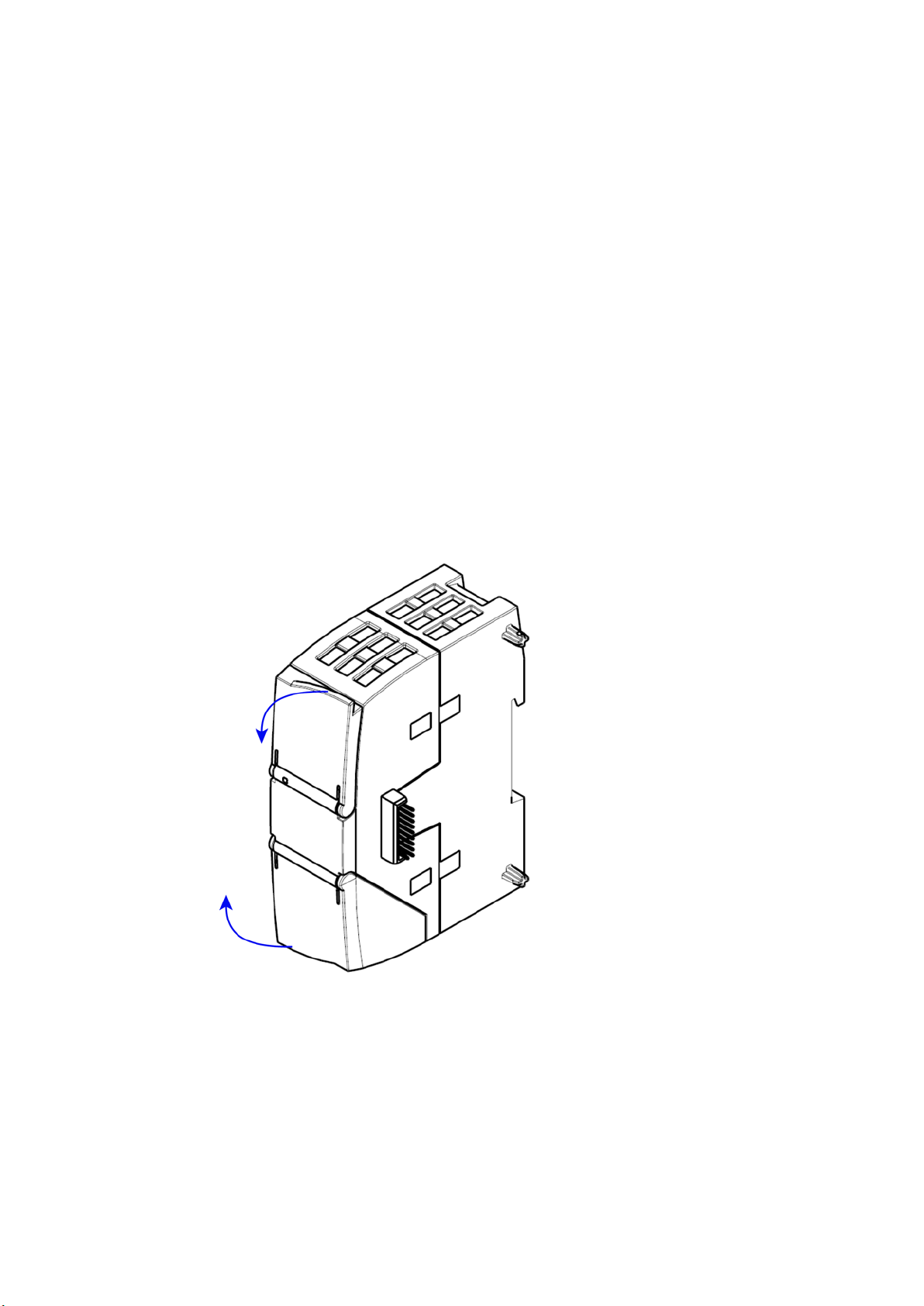
Opening the covers of the housing
Location of the display elements and the electrical connectors
Opening the covers of the housing
The LEDs for the detailed display of the module statuses are located behind the upper cover
of the module housing.
The Ethernet connector is located behind the lower hinged cover of the module.
Open the upper or lower cover of the housing by pulling it down or up as shown by the
arrows in the illustration. The covers extend beyond the housing to give you a grip.
Figure 3-1 Opening the covers of the housing
CP 1243-1 DNP3, CP 1243-1 IEC
Operating Instructions, 02/2014, C79000-G8976-C312-02
19
LEDs and connectors
3.2
LEDs
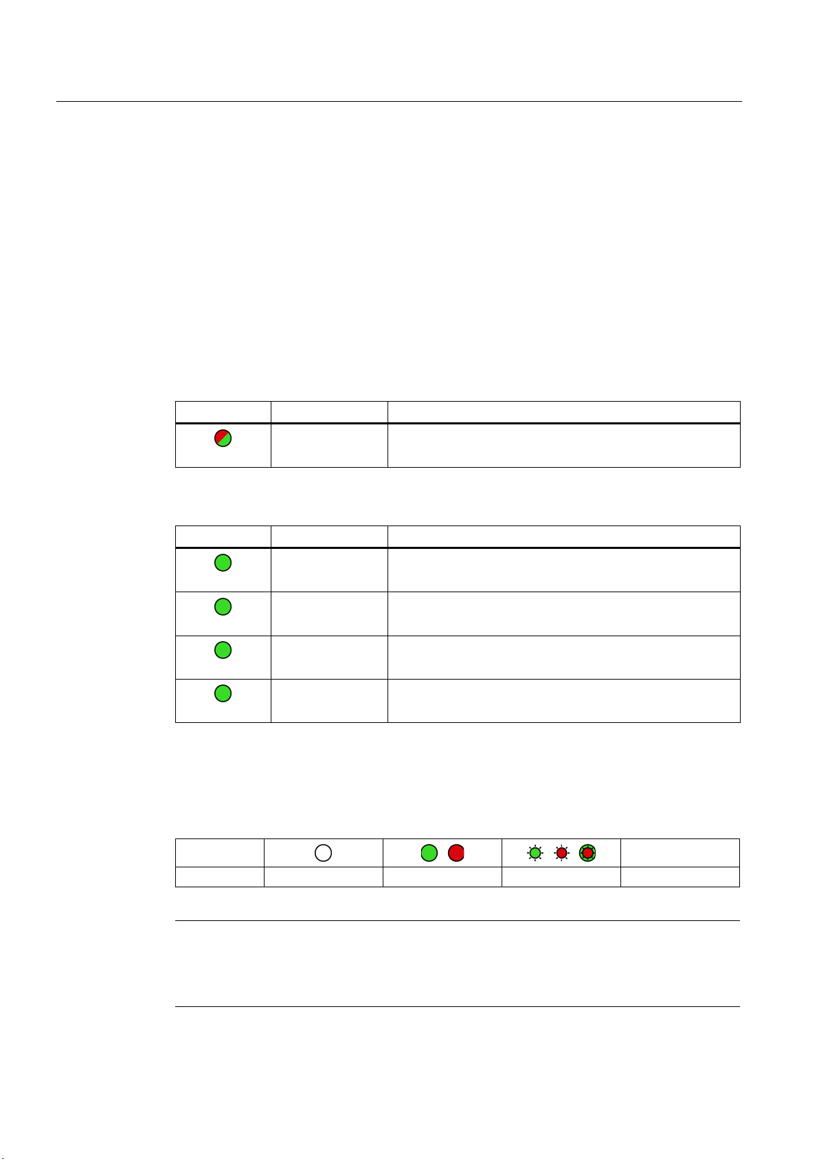
LEDs of the module
LED on the front panel
LEDs below the upper cover of the housing
LED on the front panel
LED / colors
Name
Meaning
(red / green)
DIAG
LEDs below the upper cover of the housing
LED (color)
Name
Meaning
(green)
LINK
(green)
CONNECT
(green)
VPN
(green)
SERVICE
LED colors and illustration of the LED statuses
Meaning of the LED symbols
Symbol
LED status
OFF
ON (steady light)
Flashing
Not relevant
Note
LED colors when the module starts up
When
color mixture. At this point in time, the color of the LEDs is not clear.
3.2 LEDs
The module has various LEDs for displaying the status:
●
The "DIAG" LED that is always visible shows the basic statuses of the module.
●
The LEDs below the upper cover provide more detailed information on the module status.
Table 3- 1
Table 3- 2
Basic status of the module
Status of the connection to Industrial Ethernet
Status of the connections to masters
Status of a connection for online functions
- inactive -
The LED symbols in the following tables have the following significance:
Table 3- 3
the module starts up, all its LEDs are lit for a short time. Multicolored LEDs display a
CP 1243-1 DNP3, CP 1243-1 IEC
20 Operating Instructions, 02/2014, C79000-G8976-C312-02
-
LEDs and connectors
Display of the basic statuses of the CP ("DIAG" LED)
DIAG
(red / green)
Meaning
(if more than one point listed: alternative meaning)
Basic statuses of the CP
green
flashing red-green
Display of the operating and communications statuses
DIAG
-
LINK
CONNECT
VPN
SERVICE
Meaning
(if more than one point listed: alternative
meaning)
Module startup (STOP → RUN)
Error/fault states
flashing red
green
red
3.2 LEDs
Table 3- 4 Display of the basic statuses of the CP
flashing green
flashing red
• Power OFF
• Incorrect startup
Running (RUN) without serious error
• Partner not connected
• Firmware loaded successfully
• Starting up
• Module fault
• Invalid STEP 7 project data
Error loading firmware
The LEDs indicate the operating and communications status of the module according to the
following scheme:
Table 3- 5 Display of the operating and communications statuses
(red / green)
•
•
red
CP 1243-1 DNP3, CP 1243-1 IEC
Operating Instructions, 02/2014, C79000-G8976-C312-02
(green)
-
- - - - Running (RUN) without serious error
-
(green)
(green)
- - Invalid STEP 7 project data
(green)
Power OFF
Startup - phase 1
Startup - phase 2
Incorrect startup
21
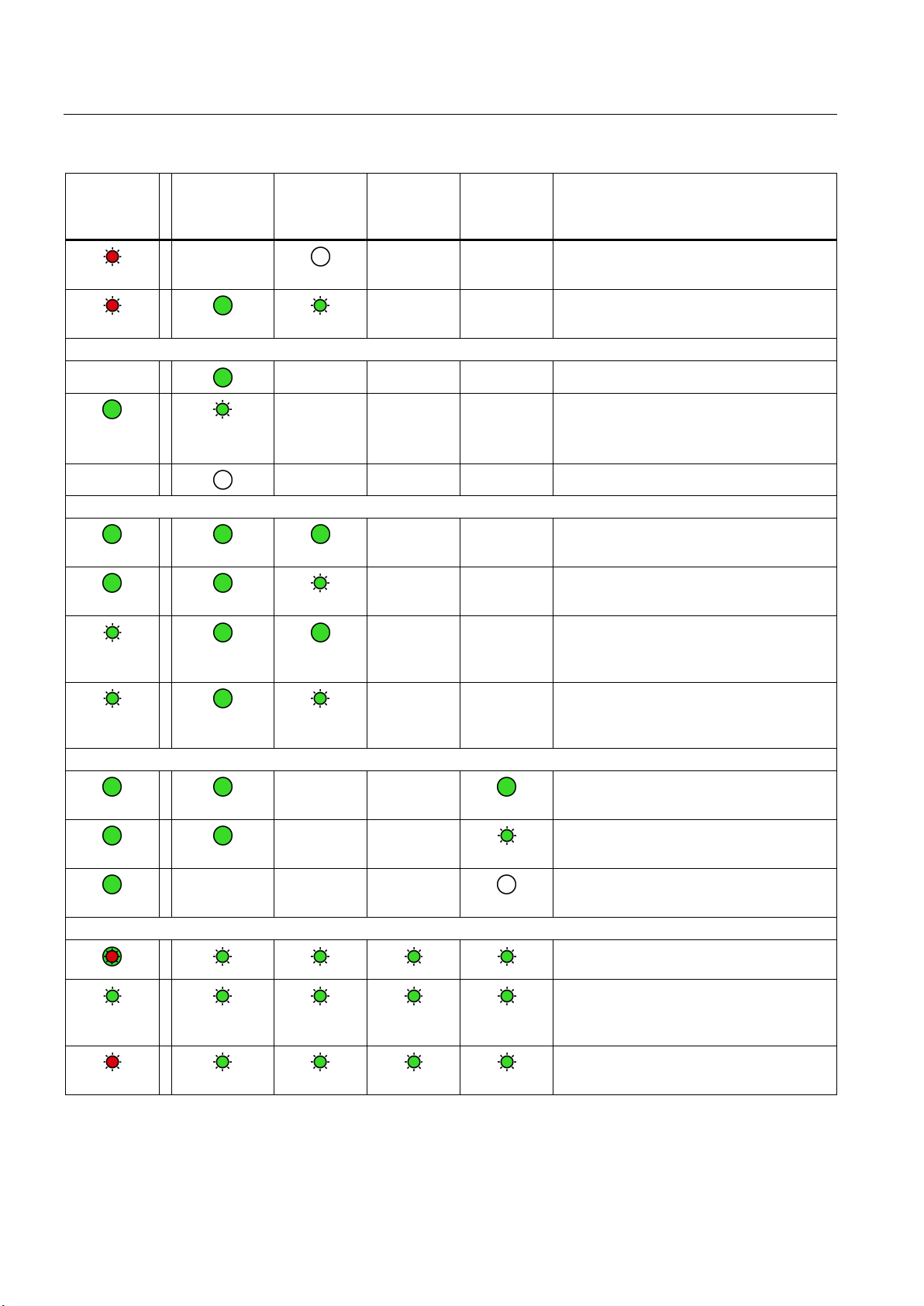
LEDs and connectors
DIAG
-
LINK
CONNECT
VPN
SERVICE
Meaning
(if more than one point listed: alternative
meaning)
flashing red
flashing red
Connection to Industrial Ethernet
Connection to communications partners
green
green
green
green
Connection for online functions
green
green
green
Loading firmware
alternating red and green.
green
flashing red
3.3 Electrical connections
(red / green)
-
green
-
flashing
(green)
-
(green)
- - - Connection to Industrial Ethernet exists
- - -
- - - No connection to Industrial Ethernet
(green)
- - Missing STEP 7 project data
- - Backplane bus error
- - Connection established to at least one
- - Partner reachable, CPU in STOP mode
- - Partner not reachable, CPU in RUN mode
(green)
• Connection to Industrial Ethernet being
established.
• IP address being obtained.
partner
flashing
flashing
- - -
- -
- -
- - Partner not reachable, CPU in STOP mode
Connection for online functions established
Attempt to establish connection for online
functions
No connection to engineering station
Loading firmware. The DIAG LED flashes
Firmware was successfully loaded.
Error loading firmware
CP 1243-1 DNP3, CP 1243-1 IEC
22 Operating Instructions, 02/2014, C79000-G8976-C312-02

LEDs and connectors
3.3
Electrical connections
3.3.1
Power supply
Power supply
3.3.2
Ethernet interface X1P1
Ethernet interface
3.3 Electrical connections
The CM is supplied with power from the backplane bus. It does not require a separate power
supply.
The Ethernet connector is located behind the lower hinged cover of the module. The
interface is an RJ-45 jack according to IEEE 802.3.
The pin assignment and other data relating to the Ethernet interface can be found in the
section Technical specifications (Page 63).
CP 1243-1 DNP3, CP 1243-1 IEC
Operating Instructions, 02/2014, C79000-G8976-C312-02
23
Loading...