

Siemens RUGGEDCOM RX1510, RUGGEDCOM RX1512, RUGGEDCOM RX1511, SIMATIC NET RUGGEDCOM RX1501, SIMATIC NET RUGGEDCOM RX1500 Installation Manual
Installation Manual
SIMATIC NET
Rugged Multi Service Platforms
RUGGEDCOM RX1510
Edition 12/2019
https://www.siemens.com
Preface
SIMATIC NET
Rugged Multi Service Platforms
RUGGEDCOM RX1510
Installation Manual
Introduction
Installing the Device
Device Management
Modules
Technical Specifications
Certification
1
2
3
4
5
6
12/2019
C79000-G8976-1055-16
Legal Information
Warning Notice System
This manual contains notices you have to observe in order to ensure your personal safety, as well as to prevent
damage to property. The notices referring to your personal safety are highlighted in the manual by a safety
alert symbol, notices referring only to property damage have no safety alert symbol. These notices shown below are graded according to the degree of danger.
DANGER
indicates that death or severe personal injury will result if proper precautions are not taken.
WARNING
indicates that death or severe personal injury may result if proper precautions are not taken.
CAUTION
indicates that minor personal injury can result if proper precautions are not taken.
NOTICE
indicates that property damage can result if proper precautions are not taken.
If more than one degree of danger is present, the warning notice representing the highest degree of danger
will be used. A notice warning of injury to persons with a safety alert symbol may also include a warning relating to property damage.
Qualified Personnel
The product/system described in this documentation may be operated only by personnel qualified for the
specific task in accordance with the relevant documentation, in particular its warning notices and safety instructions. Qualified personnel are those who, based on their training and experience, are capable of identifying risks and avoiding potential hazards when working with these products/systems.
Proper Use of Siemens Products
Note the following:
WARNING
Siemens products may only be used for the applications described in the catalog and in the relevant technical
documentation. If products and components from other manufacturers are used, these must be recommended or approved by Siemens. Proper transport, storage, installation, assembly, commissioning, operation and
maintenance are required to ensure that the products operate safely and without any problems. The permissible ambient conditions must be complied with. The information in the relevant documentation must be observed.
Trademarks
All names identified by ® are registered trademarks of Siemens AG. The remaining trademarks in this publication may be trademarks whose use by third parties for their own purposes could violate the rights of the owner.
Disclaimer of Liability
We have reviewed the contents of this publication to ensure consistency with the hardware and software described. Since variance cannot be precluded entirely, we cannot guarantee full consistency. However, the information in this publication is reviewed regularly and any necessary corrections are included in subsequent
editions.
Siemens AG
Digital Industry
Process Automation
Postfach 48 48
90026 NÜRNBERG
GERMANY
© 12/2019 Subject to Change Copyright © Siemens 2019
All rights reserved

Table of Contents
Preface ............................................................................................................................................ v
Related Documents ................................................................................................................. v
Accessing Documentation ....................................................................................................... v
Disclaimer of Liability .............................................................................................................. v
Registered Trademarks ........................................................................................................... vi
Training .................................................................................................................................. vi
Customer Support .................................................................................................................. vi
Contacting Siemens ............................................................................................................... vii
1 Introduction ........................................................................................................................... 1
1.1 Feature Highlights ................................................................................................. 1
1.2 Description ............................................................................................................ 1
1.3 Required Tools and Materials ................................................................................. 3
1.4 Decommissioning and Disposal ............................................................................. 3
1.5 Cabling Recommendations .................................................................................... 4
1.5.1 Protection On Twisted-Pair Data Ports .................................................................... 4
1.5.2 Gigabit Ethernet 1000Base-TX Cabling Recommendations ...................................... 4
2 Installing the Device ............................................................................................................. 5
2.1 General Procedure ................................................................................................. 6
2.2 Unpacking the Device ........................................................................................... 6
2.3 Mounting the Device ............................................................................................. 7
2.3.1 Mounting the Device on a DIN Rail ........................................................................ 7
2.3.2 Mounting the Device to a Panel ............................................................................ 8
2.4 Connecting the Failsafe Alarm Relay ...................................................................... 8
2.5 Connecting Power ................................................................................................. 9
2.5.1 Connecting High AC/DC Power ............................................................................ 10
2.5.2 Connecting Low DC Power .................................................................................. 13
3 Device Management ........................................................................................................... 19
3.1 Connecting to the Device .................................................................................... 19
3.2 Configuring the Device ........................................................................................ 20
3.3 Accessing the CompactFlash Card ........................................................................ 20
4 Modules ............................................................................................................................... 25
4.1 Available Modules ............................................................................................... 26
4.2 Installing/Removing Line Modules ........................................................................ 37
4.3 Installing/Removing Power Modules .................................................................... 39
5 Technical Specifications ...................................................................................................... 43
RUGGEDCOM RX1510
Installation Manual, 12/2019, C79000-G8976-1055-16
iii

Table of Contents
5.1 Power Supply Specifications ................................................................................ 43
5.2 Failsafe Relay Specifications ................................................................................ 43
5.3 Operating Environment ....................................................................................... 44
5.4 Mechanical Specifications .................................................................................... 44
5.5 Dimension Drawings ........................................................................................... 44
6 Certification ......................................................................................................................... 47
6.1 Approvals ............................................................................................................ 47
6.1.1 TÜV SÜD ............................................................................................................. 47
6.1.2 European Union (EU) .......................................................................................... 47
6.1.3 FCC ..................................................................................................................... 49
6.1.4 FDA/CDRH ........................................................................................................... 49
6.1.5 ISED .................................................................................................................... 49
6.1.6 RoHS ................................................................................................................... 49
6.1.7 Other Approvals .................................................................................................. 50
6.2 EMC and Environmental Type Tests ..................................................................... 50
iv
Installation Manual, 12/2019, C79000-G8976-1055-16
RUGGEDCOM RX1510

Preface
This guide describes the RUGGEDCOM RX1510. It describes the major features of the
device, installation, commissioning and important technical specifications.
It is intended for use by network technical support personnel who are responsible
for the installation, commissioning and maintenance of the device. It is also recommended for use by network and system planners, system programmers, and line
technicians.
Related Documents
Other documents that may be of interest include:
• RUGGEDCOM RX1510 CLI User Guide [https://support.industry.siemens.com/cs/-
ww/en/view/109481699]
• RUGGEDCOM RX1510 Web Interface User Guide [https://support.indus-
try.siemens.com/cs/ww/en/view/109481700]
• RUGGEDCOM RX1510 Modules Catalog [https://support.industry.siemen-
s.com/cs/ww/en/view/109747072]
Accessing Documentation
The latest user documentation for RUGGEDCOM RX1510 is available online at
https://support.industry.siemens.com. To request or inquire about a user document,
contact Siemens Customer Support.
Disclaimer of Liability
Siemens has verified the contents of this document against the hardware and/or software described. However, deviations between the product and the documentation
may exist.
Siemens shall not be liable for any errors or omissions contained herein or for consequential damages in connection with the furnishing, performance, or use of this material.
The information given in this document is reviewed regularly and any necessary corrections will be included in subsequent editions. We appreciate any suggested improvements. We reserve the right to make technical improvements without notice.
RUGGEDCOM RX1510
Installation Manual, 12/2019, C79000-G8976-1055-16
v
Preface
Registered Trademarks
Registered Trademarks
RUGGEDCOM™ and ROS™ are trademarks of Siemens AG.
Linux® is the registered trademark of Linus Torvalds in the United States and other
countries.
The registered trademark Linux® is used pursuant to a sublicense from LMI, the ex-
clusive licensee of Linus Torvalds, owner of the mark on a world-wide basis.
Other designations in this manual might be trademarks whose use by third parties
for their own purposes would infringe the rights of the owner.
Training
Siemens offers a wide range of educational services ranging from in-house training
of standard courses on networking, Ethernet switches and routers, to on-site customized courses tailored to the customer's needs, experience and application.
Siemens' Educational Services team thrives on providing our customers with the essential practical skills to make sure users have the right knowledge and expertise to
understand the various technologies associated with critical communications network infrastructure technologies.
Siemens' unique mix of IT/Telecommunications expertise combined with domain
knowledge in the utility, transportation and industrial markets, allows Siemens to
provide training specific to the customer's application.
For more information about training services and course availability, visit https://-
www.siemens.com or contact a Siemens Sales representative.
Customer Support
Customer support is available 24 hours, 7 days a week for all Siemens customers.
For technical support or general information, contact Siemens Customer Support
through any of the following methods:
Online
Visit http://www.siemens.com/automation/support-request to submit a
Support Request (SR) or check on the status of an existing SR.
Telephone
vi
Call a local hotline center to submit a Support Request (SR). To locate a local hotline center, visit https://w3.siemens.com/aspa_app/?lang=en.
Mobile App
Install the Industry Online Support app by Siemens AG on any Android,
Apple iOS or Windows mobile device and be able to:
• Access Siemens' extensive library of support documentation, including FAQs and manuals
Installation Manual, 12/2019, C79000-G8976-1055-16
RUGGEDCOM RX1510
Contacting Siemens
Address Siemens AG
Telephone Toll-free: 1 888 264 0006
E-Mail ruggedcom.info.i-ia@siemens.com
Web https://www.siemens.com
Preface
Contacting Siemens
• Submit SRs or check on the status of an existing SR
• Contact a local Siemens representative from Sales, Technical Support,
Training, etc.
• Ask questions or share knowledge with fellow Siemens customers
and the support community
Industry Sector
300 Applewood Crescent
Concord, Ontario
Canada, L4K 5C7
Tel: +1 905 856 5288
Fax: +1 905 856 1995
RUGGEDCOM RX1510
Installation Manual, 12/2019, C79000-G8976-1055-16
vii

Preface
Contacting Siemens
viii
Installation Manual, 12/2019, C79000-G8976-1055-16
RUGGEDCOM RX1510

Introduction
The RUGGEDCOM RX1510 is a cost-efficient, rugged Layer 3 switch and router. The
RUGGEDCOM RX1510’s modular and field replaceable platform can be equipped with
WAN, serial, and Ethernet options, making it ideally suited for electric power utilities,
the industrial plant floor, and traffic control systems. The appliance’s compact form
factor makes it ideal for pole mount applications or installation in restricted spaces.
The RUGGEDCOM RX1510 is designed to provide a high level of immunity to electromagnetic interference (EMI) and heavy electrical surges typical of the harsh environments found in many industrial applications. An operating temperature range of -40
to 85 °C (-40 to 185 °F) allows the RUGGEDCOM RX1510 to be placed in almost any
location.
1.1 Feature Highlights
1
Reliability in Harsh Environments
• Immunity to EMI and high voltage
electrical transients
• -40 to 85 °C (-40 to 185 °F) operating temperature (no fans)
• Failsafe output relay for critical failure or error alarming
Universal Power Supply Options
• Dual redundant, modular, hot-swappable power supplies
• Fully integrated power supplies (no
external adapters)
• Input voltage ranges: 13-36 VDC
and 37-72 VDC or 85-264 VAC and
88-300 VDC for worldwide operability
• CSA/UL 60950-1 safety approved to
85 °C (185 °F)
Physical Ports
• Field replaceable line modules
• Up to 24 100Base-FX ports
• Up to 24 10/100Base-TX ports
• Up to 12 10Base-FL/100Base-SX
ports
• Up to 8 Gigabit Ethernet ports
• Up to 24 serial ports
• Up to 4 T1/E1 RJ48C ports or 2 E1
BNC ports
• Up to 2 DDS (Digital Data Services)
ports
• Up to 8 active cellular data interfaces
1.2 Description
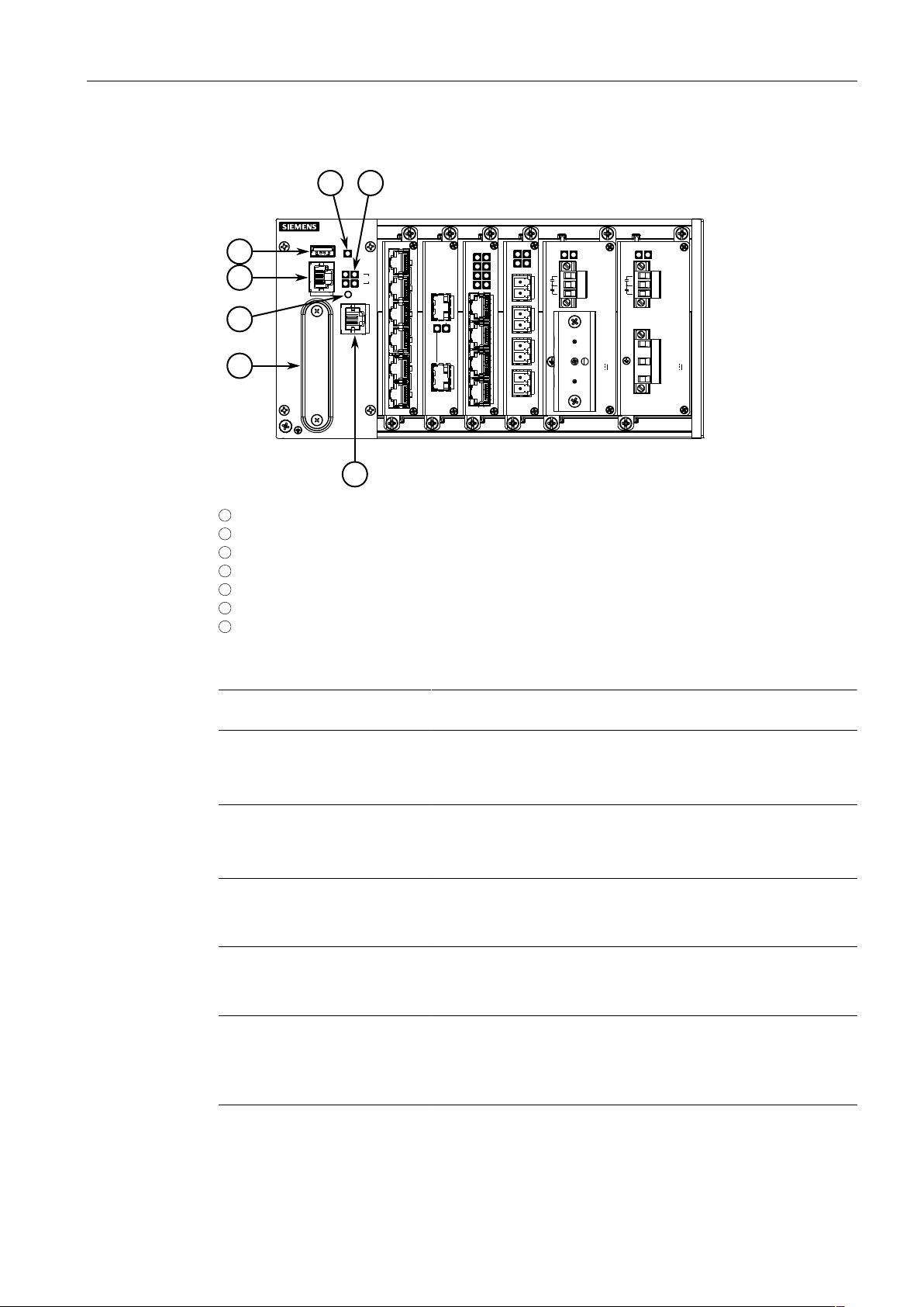
The RUGGEDCOM RX1510 features various ports, controls and indicator LEDs on the
front panel for connecting, configuring and troubleshooting the device.
RUGGEDCOM RX1510
Installation Manual, 12/2019, C79000-G8976-1055-16
1
Introduction
4
2
1
3
5 6
7
1.2Description
1
Utility USB Port
2
RS232 Serial Console Port (RJ45)
3
Lamp Test/Alarm Cut-Off (LT/ACO) Button
4
Compact Flash Card Port
5
Alarm Indicator LED
6
Port Status LEDs
7
Management Port
Figure1.1 RUGGEDCOM RX1510
Management Port This 10/100Base-T Ethernet port is used for system management
that is out-of-band from the switch fabric.
RS-232 Serial Console Port The serial console port is for interfacing directly with the device and
accessing initial management functions. For information about connecting to the device via the serial console port, refer to "Connect-
ing to the Device (Page 19)".
Utility USB Port Use the USB port to upgrade the RUGGEDCOM RX1510 software
or install files, such as configuration files and feature key files. For
more information, refer to the RUGGEDCOM RX1510 User Guide
for the RUGGEDCOM RX1510.
Lamp Test/Alarm Cut-Off (LT/
ACO) Button
This button performs two functions:
• Press and hold this button to test all indicator LEDs
• Press and release this button to acknowledge an active alarm
Power Status LEDs Indicates the status of the power modules.
• Green = Power is on
• Off = Power is off
Port Status LEDs Indicates when ports are active.
• Green = OK
• Orange = Warning alert
• Red = Configuration error
Alarm Indicator LED Indicates when an alarm condition exists.
• Green = Alarms cleared/acknowledged
2
Installation Manual, 12/2019, C79000-G8976-1055-16
RUGGEDCOM RX1510
• Red = Alarm
Compact Flash Card Port Houses the CompactFlash (CF) card that contains active and back-
up installations of RUGGEDCOM RUGGEDCOM RX1510, along with
the configuration database and other system data. For more information, refer to "Accessing the CompactFlash Card (Page 20)".
1.3 Required Tools and Materials
The following tools and materials are required to install the RUGGEDCOM RX1510:
Tools/Materials Purpose
AC/DC power cord (16 AWG) For connecting power to the device.
Lightning protector For protecting the device from harmful electrical
Shielded coaxial cables For connecting the device to antennas and an Eth-
SIM Card(s) provided by the network carrier For accessing a network carrier's cellular net-
Flathead screwdriver For mounting the device to a DIN rail.
Phillips screwdriver For mounting the device to a panel.
4 x #6-32 screws For mounting the device to a panel.
Braided or equivalent ground wire For grounding the device to safety Earth.
Introduction
1.3Required Tools and Materials
strikes.
ernet network.
work. Required only if a cellular modem module is
equipped.
1.4 Decommissioning and Disposal
Proper decommissioning and disposal of this device is important to prevent malicious
users from obtaining proprietary information and to protect the environment.
Decommissioning
This device may include sensitive, proprietary data. Before taking the device out of
service, either permanently or for maintenance by a third-party, make sure it has
been fully decommissioned.
For more information, refer to the associated User Guide.
Recycling and Disposal
For environmentally friendly recycling and disposal of this device and related accessories, contact a facility certified to dispose of waste electrical and electronic equipment. Recycling and disposal must be done in accordance with local regulations.
RUGGEDCOM RX1510
Installation Manual, 12/2019, C79000-G8976-1055-16
3
Introduction
1.5Cabling Recommendations
1.5 Cabling Recommendations
Siemens recommends using SIMATIC NET industrial Ethernet shielded cables for all
Ethernet ports.
1.5.1 Protection On Twisted-Pair Data Ports
All copper Ethernet ports on RUGGEDCOM products include transient suppression
circuitry to protect against damage from electrical transients and conform with IEC
61850-3 and IEEE 1613 Class 1 standards. This means that during a transient electrical event, communications errors or interruptions may occur, but recovery is automatic.
Siemens also does not recommend using copper Ethernet ports to interface with devices in the field across distances that could produce high levels of ground potential
rise (i.e. greater than 2500 V), during line-to-ground fault conditions.
1.5.2 Gigabit Ethernet 1000Base-TX Cabling Recommendations
The IEEE 802.3ab Gigabit Ethernet standard defines 1000 Mbit/s Ethernet communications over distances of up to 100 m (328 ft) using all 4 pairs in category 5 (or
higher) balanced, unshielded twisted-pair cabling. For wiring guidelines, system designers and integrators should refer to the Telecommunications Industry Association
(TIA) TIA/EIA-568-A wiring standard that characterizes minimum cabling performance
specifications required for proper Gigabit Ethernet operation. For reliable, error-free
data communication, new and pre-existing communication paths should be verified
for TIA/EIA-568-A compliance.
The following table summarizes the relevant cabling standards:
Cabling
Category
< 5 No New wiring infrastructure required.
5 Yes Verify TIA/EIA-568-A compliance.
5e Yes
6 Yes No action required.
> 6 Yes Connector and wiring standards to be determined.
Follow these recommendations for copper data cabling in high electrical noise environments:
1000Base-
TX Compliant
Required Action
No action required. New installations should be designed with Category 5e or higher.
• Data cable lengths should be as short as possible, preferably 3 m (10 ft) in
length. Copper data cables should not be used for inter-building communications.
• Power and data cables should not be run in parallel for long distances, and
should be installed in separate conduits. Power and data cables should intersect
at 90° angles when necessary to reduce inductive coupling.
4
Installation Manual, 12/2019, C79000-G8976-1055-16
RUGGEDCOM RX1510
Installing the Device
This chapter describes how to install the device, including mounting the device, connecting power, and connecting the device to the network.
DANGER
Electrocution hazard – risk of serious personal injury and/or damage to equipment.
Before performing any maintenance tasks, make sure all power to the device has
been disconnected and wait approximately two minutes for any remaining energy
to dissipate.
WARNING
Radiation hazard – risk of serious personal injury.
This product contains a laser system and is classified as a CLASS 1 LASER PRODUCT.
Use of controls or adjustments or performance of procedures other than those specified herein may result in hazardous radiation exposure.
2
WARNING
Radiation hazard – risk of Radio Frequency (RF) exposure.
This device is compliant with the requirements set forth in FCC 47 CFR, section
1.1307, addressing Radio Frequency (RF) exposure from radio frequency base stations, as defined in FCC OET Bulletin 65 [http://transition.fcc.gov/Bureaus/Engi-
neering_Technology/Documents/bulletins/oet65/oet65.pdf]. The emitted radiation
should be as little as possible. To achieve minimum RF exposure, install the device
when it is configured not to transmit and set it to operational mode remotely, rather
than having a technician enable transmission on-site. For maintenance of the base
station, or other operations which require RF exposure, the exposure should be minimized in time and according to the regulations set forth by the country of installation or the Federal Communications Commission (FCC).
NOTICE
This product contains no user-serviceable parts. Attempted service by unauthorized
personnel shall render all warranties null and void.
Changes or modifications not expressly approved by Siemens AG could invalidate
specifications, test results, and agency approvals, and void the user's authority to
operate the equipment.
RUGGEDCOM RX1510
Installation Manual, 12/2019, C79000-G8976-1055-16
5
Installing the Device
2.1General Procedure
NOTICE
This product should be installed in a restricted access location where access can only
be gained by authorized personnel who have been informed of the restrictions and
any precautions that must be taken. Access must only be possible through the use of
a tool, lock and key, or other means of security, and controlled by the authority responsible for the location.
2.1 General Procedure
The general procedure for installing the device is as follows:
NOTICE
The user is responsible for the operating environment of the device, including maintaining the integrity of all protective conductor connections and checking equipment ratings. Make sure to review all operating and installation instructions before
commissioning or performing maintenance on the device.
1. Review the relevant certification information for any regulatory requirements.
For more information, refer to "Approvals (Page 47)".
2. Review the RUGGEDCOM RX1500 Series Modules Catalog for special installation
or regulatory requirements related to the modules installed in the device. In the
case of cellular modem line modules, this includes antenna installation and regulatory requirements.
3. Mount the device.
4. Connect the failsafe alarm relay.
5. Connect power to the device and ground the device to safety Earth.
6. Connect the device to the network.
7. Configure the device.
2.2 Unpacking the Device
When unpacking the device, do the following:
1. Inspect the package for damage before opening it.
2. Visually inspect each item in the package for any physical damage.
3. Verify all items are included.
NOTICE
If any item is missing or damaged, contact Siemens for assistance.
6
Installation Manual, 12/2019, C79000-G8976-1055-16
RUGGEDCOM RX1510
2.3 Mounting the Device
1
2
3
2
1
The RUGGEDCOM RX1510 is designed for maximum mounting and display flexibility.
It can be equipped with connectors that allow it to be installed in a 35 mm (1.4 in)
DIN rail, or directly on a panel.
NOTICE
Heat generated by the device is channeled outwards from the enclosure. As such, it
is recommended that 2.5 cm (1 in) of space be maintained on all open sides of the
device to allow for some convectional airflow.
Forced airflow is not required. However, any increase in airflow will result in a reduction of ambient temperature and improve the long-term reliability of all equipment
mounted in the rack space.
Note
For detailed dimensions of the device with either DIN rail or panel hardware installed,
refer to "Dimension Drawings (Page 44)".
Installing the Device
2.3Mounting the Device
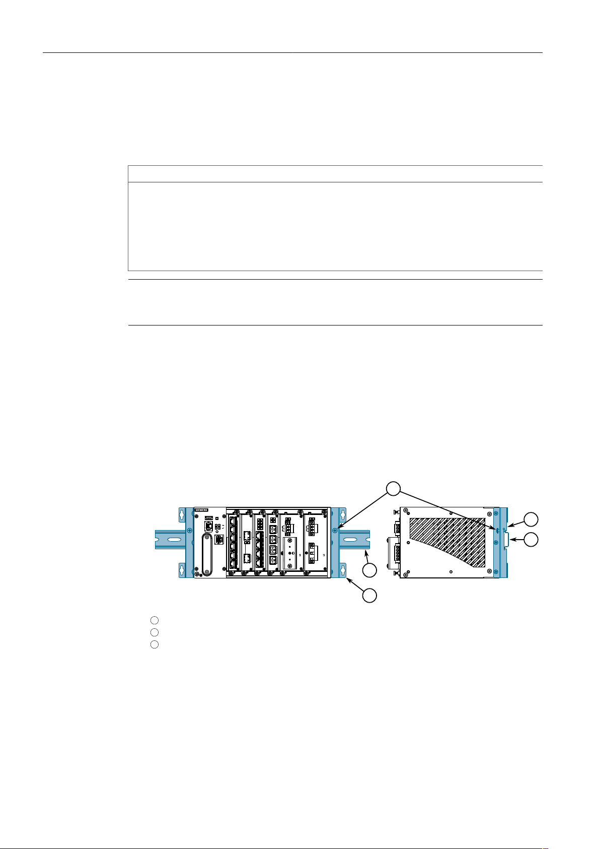
2.3.1 Mounting the Device on a DIN Rail
For DIN rail installations, the RUGGEDCOM RX1510 can be equipped with panel/DIN
rail adapters pre-installed on each side of the chassis. The adapters allow the device
to be slid onto a standard 35 mm (1.4 in) DIN rail.
To mount the device to a DIN rail, do the following:
1. Align the adapters with the DIN rails and slide the device into place.
1
Panel/DIN Rail Adapter
2
DIN Rail
3
Screw
Figure2.1 DIN Rail Mounting
2. Install one of the supplied screws on either side of the device to secure the
adapters to the DIN rails.
RUGGEDCOM RX1510
Installation Manual, 12/2019, C79000-G8976-1055-16
7
Installing the Device
1
2
1
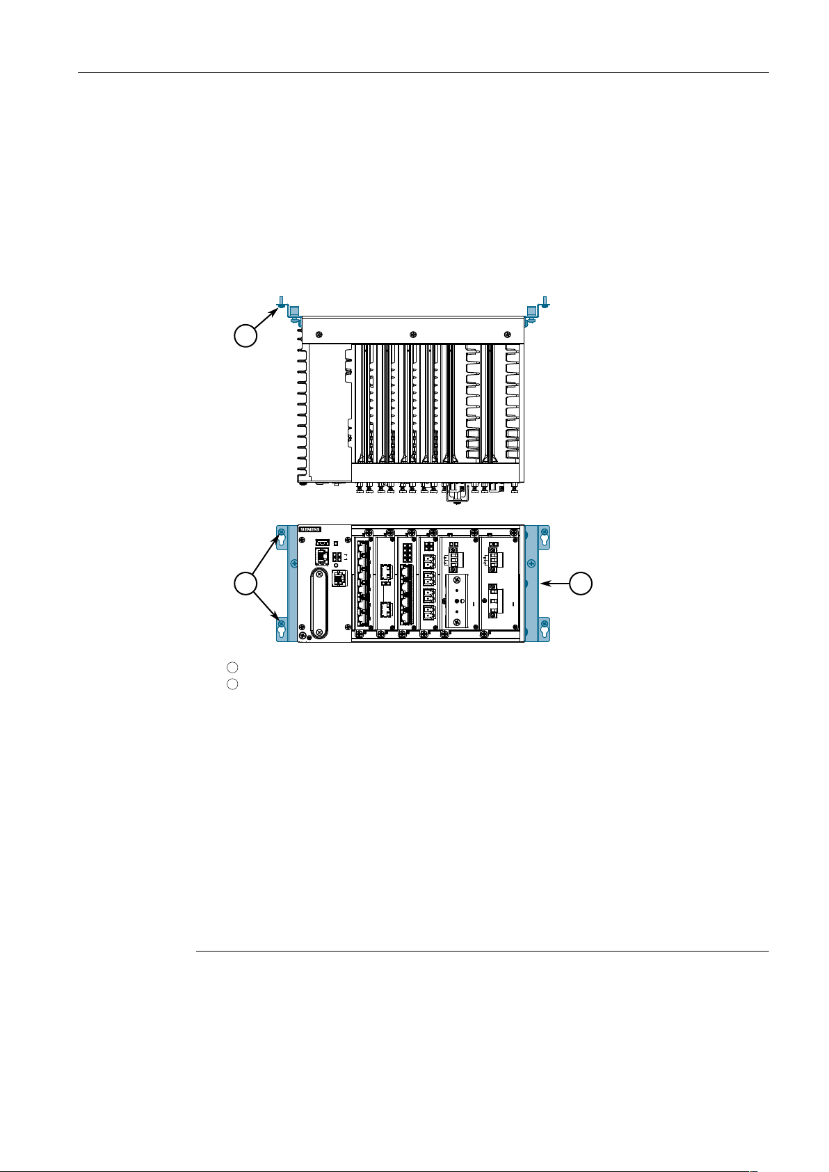
2.3.2Mounting the Device to a Panel
2.3.2 Mounting the Device to a Panel
For panel installations, the RUGGEDCOM RX1510 can be equipped with panel/DIN rail
adapters pre-installed on each side of the chassis. The adapters allow the device to
be attached to a panel using screws.
To mount the device to a panel, do the following:
1. Place the device against the panel and mark the mounting holes on the panel.
1
Screw
2
Panel/DIN Rail Adapter
Figure2.2 Panel Mounting
2. Prepare the mounting holes
3. Align the device with the mounting holes and secure it to the panel.
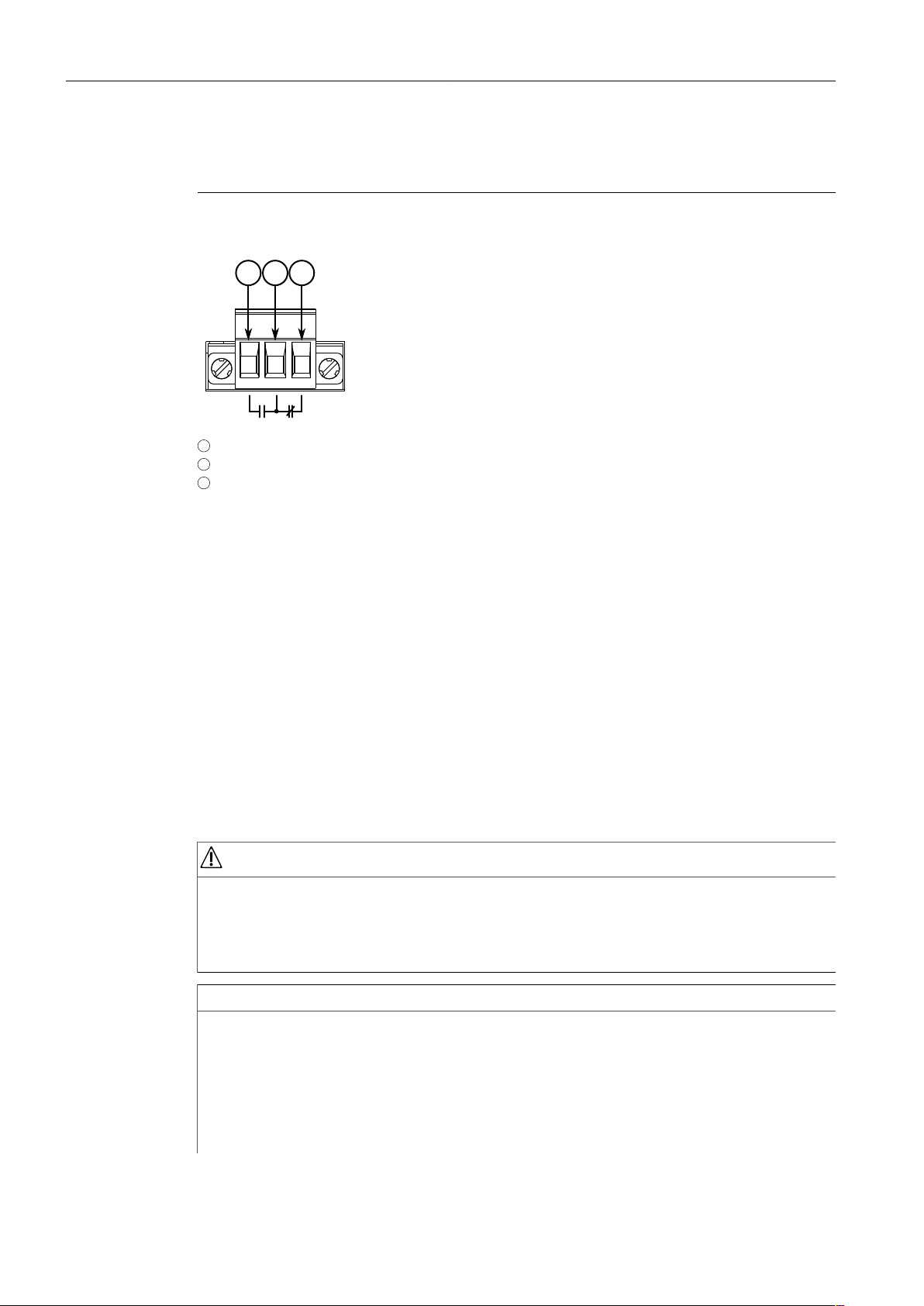
2.4 Connecting the Failsafe Alarm Relay
The failsafe relay can be configured to latch based on alarm conditions. The NO
(Normally Open) contact is closed when the unit is powered and there are no active alarms. If the device is not powered or if an active alarm is configured, the relay
opens the NO contact and closes the NC (Normally Closed) contact.
Note
Control of the failsafe relay output is configurable through RUGGEDCOM RX1510.
One common application for this relay is to signal an alarm if a power failure oc-
8
Installation Manual, 12/2019, C79000-G8976-1055-16
RUGGEDCOM RX1510
Installing the Device
2 31
2.5Connecting Power
curs. For more information, refer to the RUGGEDCOM RX1510 User Guide for the
RUGGEDCOM RX1510.
The following shows the proper relay connections.
1
Normally Open
2
Common
3
Normally Closed
Figure2.3 Failsafe Alarm Relay Wiring
2.5 Connecting Power
The RUGGEDCOM RX1510 supports dual redundant high AC, high DC and/or low DC
power modules that can be installed in any combination. The use of two power modules is recommended to provide redundancy and load balancing.
Power modules can be equipped with either a screw or European-style (Euroblock)
terminal block. The screw terminal block is installed using Phillips screws and compression plates, allowing either bare wire connections or crimped terminal lugs. Use
#6 size ring lugs for secure, reliable connections under severe shock or vibration.
For information about installing or removing a power module, refer to "Installing/Re-
moving Power Modules (Page 39)".
DANGER
Electrocution hazard – risk of serious personal injury or death
The device may have two power modules equipped, which may be connected to
separate power sources. Make sure all power sources are off before servicing the
power module terminals.
NOTICE
• In a high AC/DC and low DC (24/48 V) power module arrangement, the placement of the AC and DC power supplies is not slot-dependent. Either power module slot can be used for AC or DC power.
• For maximum redundancy in a dual power module configuration, use two independent power sources.
RUGGEDCOM RX1510
Installation Manual, 12/2019, C79000-G8976-1055-16
• Use minimum #16 gage copper wiring when connecting terminal blocks.
9
Installing the Device
2.5.1Connecting High AC/DC Power
• The maximum wire length between the terminal block and power source must
not exceed 6 m (20 ft) for 24 V power supplies or 18 m (60 ft) for 48 V power
supplies.
• For 125/230 VAC rated equipment, an appropriately rated AC circuit breaker
must be installed.
• For 125/250 VDC rated equipment, an appropriately rated DC circuit breaker
must be installed.
• It is recommended to provide a 20 A circuit breaker for the power module.
• Equipment must be installed according to applicable local wiring codes and
standards.
2.5.1 Connecting High AC/DC Power
To connect a high AC/DC power supply to the device, do the following:
DANGER
Electrocution hazard – risk of death, serious personal injury and/or damage to
the device
Make sure the supplied cover is always installed over high voltage screw terminal
blocks.
CAUTION
Electrical hazard – risk of damage to equipment
Do not connect AC power cables to a 12, 24 or 48 VDC power supply terminal block.
Damage to the power supply may occur.
Note
The screw terminal block is installed using Phillips screws and compression plates, allowing either bare wire connections or crimped terminal lugs. Use #6 size ring lugs
for secure, reliable connections.
10
Installation Manual, 12/2019, C79000-G8976-1055-16
RUGGEDCOM RX1510
 Loading...