

Siemens SIMATIC NET PROFIBUS OBT User Manual

Contents
0
SIMATIC NET
PROFIBUS Optical Bus Terminal (OBT)
Manual
Introduction
The SIMATIC NET PROFIBUS
OBT Product
Functional Description
Network Topology
Installation and Startup
Troubleshooting
Technical Specifications
Notes on the CE Label
References
1
2
3
4
5
6
7
8
9
C79000-G8976-C122-03
Release 2
Abbreviations
1

Safety Guidelines
This manual contains notices which you should observe to ensure your own personal safety, as well as to
protect the product and connected equipment. These notices are highlighted in the manual by a warning
triangle and are marked as follows according to the level of danger:
Danger
!
indicates that death, severe personal injury or substantial property damage will result if proper
precautions are not taken.
Warning
!
indicates that death, severe personal injury or substantial property damage can result if proper
precautions are not taken.
Caution
!
indicates that minor personal injury or property damage can result if proper precautions are not taken.
Note
draws your attention to particularly important information on the product, handling the product, or to a
particular part of the documentation.
Qualified Personnel
Only qualified personnel should be allowed to install and work on this equipment Qualified persons are
defined as persons who are authorized to commission, to ground, and to tag circuits, equipment, and systems in accordance with established safety practices and standards.
Correct Usage
Note the following:
Warning
!
Trademarks
This device and its components may only be used for the applications described in the catalog or the
technical description, and only in connection with devices or components from other manufacturers which
have been approved or recommended by Siemens.
This product can only function correctly and safely if it is transported, stored, set up, and installed correctly, and operated and maintained as recommended.
SIMATIC, SIMATIC HMI and SIMATIC NET are registered trademarks of SIEMENS AG.
Third parties using for their own purposes any other names in this document which refer to trademarks
might infringe upon the rights of the trademark owners.
Disclaimer of LiabilityCopyright Siemens AG 1998 All rights reserved
The reproduction, transmission or use of this document or its contents is not
permitted without express written authority. Offenders will be liable for
damages. All rights, including rights created by patent grant or registration of
a utility model or design, are reserved.
Siemens AG
Bereich Automatisierungstechnik
Geschäftsgebiet Industrie-Automatisierung
Postfach 4848, D-90327 Nürnberg
Index-2
Siemens Aktiengesellschaft Order no. C79000-G8976-C122
We have checked the contents of this manual for agreement with the hardware and software described. Since deviations cannot be precluded entirely,
we cannot guarantee full agreement. However, the data in this manual are
reviewed regularly and any necessary corrections included in subsequent
editions. Suggestions for improvement are welcomed.
Siemens AG 1998
Subject to technical change.
PROFIBUS Optical Bus Terminal (OBT)
C79000-G8976-C122-03

C
ontents
Contents
1 Introduction 1-1. . . . . . . . . . . . . . . . . . . . . . . . . . . . . . . . . . . . . . . . . . . . . . . . . . . . . . . . . . . .
2 The SIMATIC NET PROFIBUS OBT Product 2-1. . . . . . . . . . . . . . . . . . . . . . . . . . . . . . .
3 Functional Description 3-1. . . . . . . . . . . . . . . . . . . . . . . . . . . . . . . . . . . . . . . . . . . . . . . . . .
3.1 Interfaces 3-1. . . . . . . . . . . . . . . . . . . . . . . . . . . . . . . . . . . . . . . . . . . . . . . . . . . . . .
3.2 Optoelectric Signal Conversion and Signal Regeneration 3-1. . . . . . . . . . . . .
3.3 Automatic Transmission Rate Detection 3-2. . . . . . . . . . . . . . . . . . . . . . . . . . . .
3.4 Supported FO Fiber Types 3-2. . . . . . . . . . . . . . . . . . . . . . . . . . . . . . . . . . . . . . .
3.5 Displays 3-2. . . . . . . . . . . . . . . . . . . . . . . . . . . . . . . . . . . . . . . . . . . . . . . . . . . . . . .
3.6 Operator Controls 3-4. . . . . . . . . . . . . . . . . . . . . . . . . . . . . . . . . . . . . . . . . . . . . . .
4 Network Topology 4-1. . . . . . . . . . . . . . . . . . . . . . . . . . . . . . . . . . . . . . . . . . . . . . . . . . . . . .
4.1 Optical Bus 4-1. . . . . . . . . . . . . . . . . . . . . . . . . . . . . . . . . . . . . . . . . . . . . . . . . . . . .
4.2 Using Long Fiber Optic Sections 4-2. . . . . . . . . . . . . . . . . . . . . . . . . . . . . . . . . .
4.3 Attaching RS-485 Segments 4-3. . . . . . . . . . . . . . . . . . . . . . . . . . . . . . . . . . . . . .
5 Installation and Startup 5-1. . . . . . . . . . . . . . . . . . . . . . . . . . . . . . . . . . . . . . . . . . . . . . . . .
5.1 Precedure for Installation 5-2. . . . . . . . . . . . . . . . . . . . . . . . . . . . . . . . . . . . . . . . .
5.2 Installation 5-3. . . . . . . . . . . . . . . . . . . . . . . . . . . . . . . . . . . . . . . . . . . . . . . . . . . . .
6 Troubleshooting 6-1. . . . . . . . . . . . . . . . . . . . . . . . . . . . . . . . . . . . . . . . . . . . . . . . . . . . . . . .
7 Technical Specifications 7-1. . . . . . . . . . . . . . . . . . . . . . . . . . . . . . . . . . . . . . . . . . . . . . . .
8 Notes on the CE Label 8-1. . . . . . . . . . . . . . . . . . . . . . . . . . . . . . . . . . . . . . . . . . . . . . . . . .
9 References 9-1. . . . . . . . . . . . . . . . . . . . . . . . . . . . . . . . . . . . . . . . . . . . . . . . . . . . . . . . . . . . .
10 Abbreviations 10-1. . . . . . . . . . . . . . . . . . . . . . . . . . . . . . . . . . . . . . . . . . . . . . . . . . . . . . . . . .
PROFIBUS Optical Bus Terminal (OBT)
C79000-G8976-C122-03
i

Contents
C
ontents
ii
PROFIBUS Optical Bus Terminal (OBT)
C79000-G8976-C122-03
Introduction
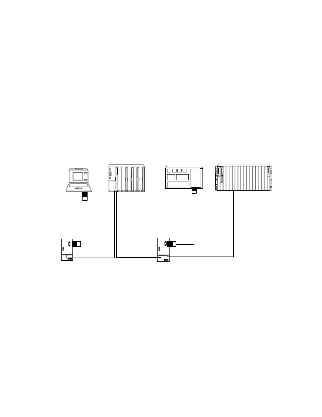
The PROFIBUS OBT (Optical Bus Terminal) is a network component for use in
optical PROFIBUS DP fieldbus networks. It allows the attachment of a single
device without an integrated optical interface to the optical PROFIBUS DP. The
following figure illustrates a typical configuration.
1
PC
Programming Device
Operator Panel
À
1)
OBT
À
À
Terminating resistor activted
1) PROFIBUS cable (terminated at both ends)
2) Plastic FO cable or PCF FO cable with two fibers
Figure 1-1 Example of an Optical PROFIBUS DP Configuration
ET 200M with
FO interface
2)
2)
DP node without
FO interface
OBT
À
SIMATIC S7-400
with IM 467 FO
À
1)
2)
PROFIBUS Optical Bus Terminal (OBT)
C79000-G8976-C122-03
1-1

Introduction
Connections
The connection between the individual nodes takes the form of an optical bus with
two-fiber plastic FO cables (plastic fiber-optic cables are also known as POF,
Polymer Optical Fiber) or PCF FO cables (PCF = Polymer Cladded Fiber,
corresponds to HCS 1) fiber-optic cable). Since fiber-optic cables are
completely insensitive to electromagnetic disturbance, no grounding concept
whatsoever is necessary. For the same reason, equipotential bonding is also not
necessary. The optoelectronic conversion provides automatic isolation so that
differences in potential as can occur in extensive systems have no effect.
1)
Company and stands for “Hard Polymer Cladded Silica Fiber”.
Sensitivity
Just as fiber-optic cable is insensitive to electromagnetic noise, a fiber-optic cable
emits no electromagnetic noise into the environment. Sensitive electronic devices
close to the fiber-optic cable therefore need no additional protection or noise
suppression.
HCS is a registered trademark of Ensign-Bickford Optics
Power Supply
The OBT requires an operating power supply of 24 V direct voltage that is
connected via two terminal screws.
Operating Mode
LEDs signal the current mode and any problems in operation.
Mechanical Design
The optical bus terminal consists of a compact plastic casing which can be
installed either on a standard rail or on any flat surface.
1-2
PROFIBUS Optical Bus Terminal (OBT)
C79000-G8976-C122-03

The SIMATIC NET PROFIBUS OBT Product
Supplied
1 x PROFIBUS OBT
1 x order form for the PROFIBUS OBT operating instructions
Not supplied
Plastic fiber-optic cable, can be purchased by the meter
Tools for connectoring fiber-optic cables
PROFIBUS OBT operating instructions
Fiber-optic cable connectors
2
PROFIBUS Optical Bus Terminal (OBT)
C79000-G8976-C122-03
2-1

The SIMATIC NET PROFIBUS OBT Product
2-2
PROFIBUS Optical Bus Terminal (OBT)
C79000-G8976-C122-03

Functional Description
The OBT is a repeater with 3 channels.
3.1 Interfaces
The OBT has the following interfaces for attachment to PROFIBUS DP segments:
Channel 1 (CH1) is an electrical RS-485 interface. This is implemented as a
9-pin D SUB female connector. A single PROFIBUS DP node can be connected
via this channel or a PC, PG or OP can be connected to the OBT. The
maximum permitted segment length is 100 m. The copper segment should,
however, be kept as short as possible since disturbances can be coupled into
the optical PROFIBUS DP from this segment.
Channel 2 (CH2) and channel 3 (CH3) are optical interfaces. They are designed
as duplex sockets. The end of a two-fiber plastic or PCF fiber-optic cable with
two simplex connectors is connected to each of these duplex sockets.
The OBT also has a block with three terminals for connecting the 24 V power
supply and, if necessary, a grounding conductor.
3
3.2 Optoelectric Signal Conversion and Signal Regeneration
The OBT converts the RS-485 level signal received at channel 1 into an optical
signal level that is then output via channel 2 and channel 3.
Signals received in channel 2 or 3 are converted to electrical signals and
output on channel 1 as an electrical signal
changed back to an optical signal and then output again on the other optical
channel.
The receive channels have no echo, in other words received signals are not sent
back on the same channel.
The OBT regenerates the signals in amplitude and time. This allows up to 126
modules to be cascaded in an optical bus. The cascading depth is limited solely by
the monitoring times of the attached devices.
The propagation delay per OBT is 6 bit times.
PROFIBUS Optical Bus Terminal (OBT)
C79000-G8976-C122-03
3-1

Functional Description
3.3 Automatic Transmission Rate Detection
The OBT supports all PROFIBUS transmission rates (12 Mbps , 6 Mbps, 3 Mbps,
1.5 Mbps, 500 Kbps and 187.5 Kbps, 93.75 Kbps, 45.45 Kbps, 19.2 Kbps, 9.6
Kbps).
The transmission rate is detected automatically. No settings are necessary.
3.4 Supported FO Fiber Types
The OBT supports the fiber types listed in the table below:
Table 3-1 Distance Covered by Fiber-optic Cable between Two Devices on the Optical
PROFIBUS DP
Fiber Type Distance Between Two Devices
Plastic FO 980/1000 µm with 2 fibers
and max. 200 dB/km cable attenuation
PCF FO 200/230 µm with 2 fibers and
max. 10 dB/km cable attenuation
0.1 m to 50 m
0 m to 300 m
The specified distances between the devices assume that the partner devices use
the same optical components as the OBT. This is, for example, the case with the
IM 153-2 FO, IM 467 FO and OLM 12M.
The transmission rate is independent of the type of fiber used and the cable length.
It can be up to 12 Mbps.
The following accessories are available:
Plastic FO cable (sold in meters), connectors, polishing set and tools for
connectoring plastic FO cables
The plastic fiber-optic cables are supplied with connectors. The plastic simplex
connectors can be fitted with the available tools on site.
PCF FO cable (with connectors)
PCF cables in fixed lengths are available with 4 simplex connectors already
fitted.
3.5 Displays
The OBT has 4 LEDs for displaying the various states.
3-2
PROFIBUS Optical Bus Terminal (OBT)
C79000-G8976-C122-03
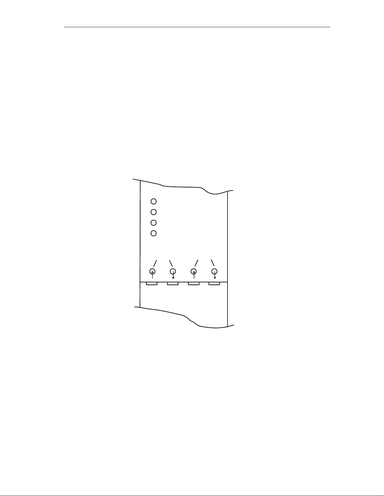
L+ 24V (green)
Unlit: No power supply or internal power supply is
defective or short-circuited
Flashes: Power supply present; Transmission rate
not yet set
Lit green: Transmission rate set, power supply
O.K.
CH1, CH2 , CH3 (channel 1 to 3, yellow)
Unlit: No data being received
Lit yellow: Data being received
L + 24V
CH1
CH2
Functional Description
CH3
CH2 CH3
Figure 3-1 LED Displays on the Front Panel
PROFIBUS Optical Bus Terminal (OBT)
C79000-G8976-C122-03
3-3

Functional Description
3.6 Operator Controls
The OBT itself does not have operator controls. Care must simply be taken that
the PROFIBUS connecting cable (not supplied) attached to Channel 1 is
terminated at both ends.
3-4
PROFIBUS Optical Bus Terminal (OBT)
C79000-G8976-C122-03
 Loading...