

Page 1

Preface, Contents
Introduction
1
Inserting the SIM card
2
Connecting the device and
switching on the device
3
MODEM MD720 in Terminal
Mode
4
MODEM MD720 in OPC Mode
5
Service function
6
Technical Data
7
Glossary
Release 07/2013
SIMATIC NET
GPRS/GSM-Modem
MODEM MD720
System manual
DRAFT
Page 2

Safety Guidelines
This manual contains notices you have to observe in order to ensure your personal safety, as well as to prevent
damage to property. The notices referring to your personal safety are highlighted in the manual by a safety alert
symbol, notices referring only to property damage have no safety alert symbol. These notices shown below are
graded according to the degree of danger.
!
Danger
indicates that death or severe personal injury will result if proper precautions are not taken.
!
Warning
indicates that death or severe personal injury may result if proper precautions are not taken.
!
Caution
with a safety alert symbol, indicates that minor personal injury can result if proper precautions are not taken.
Caution
without a safety alert symbol, indicates that property damage can result if proper precautions are not taken.
Notice
indicates that an unintended result or situation can occur if the corresponding information is not taken into
account.
If more than one degree of danger is present, the warning notice representing the highest degree of danger will
be used. A notice warning of injury to persons with a safety alert symbol may also include a warning relating to
property damage.
Qualified Personnel
The device/system may only be set up and used in conjunction with this documentation. Commissioning and
operation of a device/system may only be performed by qualified personnel. Within the context of the safety notes
in this documentation qualified persons are defined as persons who are authorized to commission, ground and
label devices, systems and circuits in accordance with established safety practices and standards.
Prescribed Usage
Note the following:
!
Warning
This device may only be used for the applications described in the catalog or the technical description and only in
connection with devices or components from other manufacturers which have been approved or recommended by
Siemens. Correct, reliable operation of the product requires proper transport, storage, positioning and assembly
as well as careful operation and maintenance.
Trademarks
All names identified by ® are registered trademarks of the Siemens AG. The remaining trademarks in this
publication may be trademarks whose use by third parties for their own purposes could violate the rights of the
owner.
Disclaimer of Liability
We have reviewed the contents of this publication to ensure consistency with the hardware and software
described. Since variance cannot be precluded entirely, we cannot guarantee full consistency. However, the
information in this publication is reviewed regularly and any necessary corrections are included in subsequent
editions.
Siemens AG
Postfach 48 48
90437 NÜRNBERG
DEUTSCHLAND
Release 05/2006
Copyright © Siemens AG 2013
Technical data subject to change
2
Page 3

!
Warning
The power supply unit to supply the MODEM MD720 must comply with NEC Class 2
circuits as outlined in the National Electrical Code (ANSI/NFPA 70) only.
General
The product MODEM MD720 complies with European standard EN60950-1 Safety of
Information Technology Equipment.
Read the installation instructions carefully before using the device.
Keep the device away from children, especially small children.
The device must not be installed or operated outdoors or at damp locations.
Do not operate the device if the connecting leads or the device itself are damaged.
External power supply
Use only an external power supply which also complies with EN60950-1. The output
voltage of the external power supply must not exceed 30VDC. The output of the
external power supply must be short-circuit proof.
When connecting to a battery or accumulator, make sure that an all-pole circuitbreaker (main battery switch) with sufficient selectivity and a fuse with sufficient
selectivity (e.g 32 V, 3A) are provided between the device and the battery or
accumulator.
Please pay regard to section 7 Technical Data of the system manual, as well as the
installation and utilization regulations of the respective manufacturers of the power
supply, the battery or the accumulator.
Handling cables
Never pull a cable connector out of a socket by its cable, but pull on the connector
itself. Cable connectors with screw fasteners (D-Sub) must always be screwed on
tightly. Do not lay the cable over sharp corners and edges without edge protection. If
necessary, provide sufficient strain relief for the cables.
For safety reasons, make sure that the bending radius of the cables is observed.
Failure to observe the bending radius of the antenna cable results in the deterioration
of the system's transmission and reception properties. The minimum bending radius
static must not fall below 5 times the cable diameter and dynamic below 15 times the
cable diameter.
Fehler! Verweisquelle konnte nicht gefunden werden. 3
Page 4

!
Warning
Never use the device in places where the operation of radio devices is prohibited. The
device contains a radio transmitter which could in certain circumstances impair the
functionality of electronic medical devices such as hearing aids or pacemakers. You
can obtain advice from your physician or the manufacturer of such devices. To prevent
data carriers from being demagnetized, do not keep disks, credit cards or other
magnetic data carriers near the device.
!
Warning
The emission limits as recommended by the Commission on Radiological Protection
(13/14 September 2001) must be observed.
Caution
The use of an outdoor antenna without adequate additional protection circuits is not
allowed. Installation must be done by a qualified person and in accordance to nationa
regulations.
Radio device
Installing antennas
Installing an external antenna
FCC Part 15
This equipment has been tested and found to comply with the limits for a Class A
digital device, pursuant to Part 15 of the FCC Rules. These limits are designed to
provide reasonable protection against harmful interference in a residential installation.
This equipment generates, uses and can radiate radio frequency energy and, if not
installed and used in accordance with the instructions, may cause harmful interference
to radio communications. However, there is no guarantee that interference will not
occur in a particular installation. If this equipment does cause harmful interference to
radio or television reception, which can be determined by turning the equipment off
and on, the user is encouraged to try to correct the interference by one or more of the
following measures:
Reorient or relocate the receiving antenna.
Increase the separation between the equipment and receiver.
Connect the equipment into an outlet on a circuit different from that to which
the receiver is connected.
Consult the dealer / installer or an experienced radio/TV technician for help.
4 Fehler! Verweisquelle konnte nicht gefunden werden.
Page 5

Caution
Typically, the antenna connected to the transmitter is an omni-directional antenna with
0dB gain. Using this antenna the total composite power in PCS mode is smaller than 1
watt ERP.
The internal / external antennas used for this mobile transmitter must provide a
separation distance of at least 20 cm from all persons and must not be co-located
or operating in conjunction with any other antenna or transmitter."
Caution
This is a class B equipment. This equipment can disturb other electric equipment in
living areas; in this case the operator can be demanded to carry out appropriate
measures.
FCC Part 15.19
This device complies with Part 15 of the FCC Rules. Operation is subject to the
following two conditions:
1. this device may not cause harmful interference, and
2. this device must accept any interference received, including interference that
may cause undesired operation.
FCC Part 15.21
Modifications not expressly approved by this company could void the user's authority
to operate the equipment.
Installation by qualified personnel only
You may only use the MODEM MD720 with an antenna of the MODEM MD720
accessory program.
The installation of the MODEM MD720 and the antenna as well as servicing is to be
performed by qualified technical personnel only. When servicing the antenna, or
working at distances closer than those listed below, ensure the transmitter has been
disabled.
RF Exposure mobile
Fehler! Verweisquelle konnte nicht gefunden werden. 5
Page 6

Caution
Please note that data packets exchanged for setting up connections, reconnecting,
connect attempts (e.g. Server switched off, wrong destination address, etc.) as well as
keeping the connection alive are also subject to charge.
6 Fehler! Verweisquelle konnte nicht gefunden werden.
Page 7

Preface
Purpose of this documentation
This documentation will support you on your way to successful application of
MODEM MD720. It will introduce you to the topic in clear and
straightforward steps and provide you with an overview of the hardware of
the MODEM MD720 GSM/GPRS modem. This documentation will help you
during installation and commissioning of SINAUT GSM/GPRS modem and
explains the diagnostics and service options available.
Validity of the documentation
This manual relates to the following product versions
GPRS/GSM modem MD720 hardware release 1.x
SIMATIC Technical Support
You can contact Technical Support for all A&D products
Phone: +49 (0) 180 5050 222
Fax: +49 (0) 180 5050 223
You will find further information on our Technical Support on the Web at
http://www.siemens.com/automation/service
Service & Support on the Internet
In addition to our documentation services, you can also make use of all our
knowledge on the Internet:
http://www.siemens.com/automation/service&support
Here, you will find:
Up-to-date product information (Updates), FAQs (Frequently Asked
Questions), Downloads, Tips and Tricks.
The Newsletter keeps you constantly up to date with the latest
information on the products you use.
The Knowledge Manager will find the documents you need.
In the Forum, users and specialists exchange information and
experience.
You can find your local contact for Automation & Drives in our contacts
database.
You will find information on local service, repairs, spares and much more
under the rubric "Service".
You will find the latest version of this documentation under the entry ID
22549543.
Fehler! Verweisquelle konnte nicht gefunden werden. 7
Page 8

Preface
Do you still have questions relating to the use of the products described in
the manual? If so, then please talk to your local Siemens contact.
You will find the addresses in the following sources:
On the Internet at: http://www.siemens.com/automation/partner
On the Internet at http://www.siemens.com/simatic-net specifically for
SIMATIC NET products
In the catalog CA 01
In the catalog IK PI specifically for SIMATIC NET products
SIMATIC training center
To familiarize you with the systems and products, we offer a range of
courses. Please contact your regional training center or the central training
center in
D-90327 Nuernberg.
Phone: +49 (911) 895-3200
http://www.sitrain.com
SIMATIC NET training center
For courses specifically on products from SIMATIC NET, please contact:
SIEMENS AG
Siemens AG, A&D Informations- und Trainings-Center
Dynamostr. 4
D-68165 Mannheim
Phone: +49 (621) 4 56-23 77
Fax: +49 (621) 4 56-32 68
8 Fehler! Verweisquelle konnte nicht gefunden werden.
Page 9

Contents
Preface .......................................................................................................................................... 7
1 Introduction ................................................................................................................... 11
2 Inserting the SIM card .................................................................................................. 13
3 Connecting the device and switching on the device ................................................ 14
4 MODEM MD720 in Terminal Mode ............................................................................. 19
4.1 Terminal mode activation................................................................................... 19
4.2 Operating requirements in Terminal Mode: GPRS subscriber contract ............ 20
4.3 Functions of the LEDs in Terminal Mode .......................................................... 20
4.4 Terminal mode operation ................................................................................... 21
4.5 Entering AT commands ..................................................................................... 22
4.6 Use AT commands ............................................................................................ 24
4.7 Supported AT commands in Terminal Mode ..................................................... 26
5 MODEM MD720 in OPC Mode ..................................................................................... 53
5.1 OPC Mode activation ......................................................................................... 54
5.2 Operating requirements in OPC Mode: GPRS subscriber contract .................. 54
5.3 Functions of the LEDs in OPC Mode ................................................................. 55
5.4 PIN in OPC-Mode .............................................................................................. 56
5.5 Log in to SINAUT MICRO SC ............................................................................ 58
6 Service functions .......................................................................................................... 59
6.1 Switching between Terminal mode and OPC Mode .......................................... 59
6.2 Getting the current settings and values ............................................................. 61
6.3 Load factory defaults ......................................................................................... 62
7 Technical Data .............................................................................................................. 63
Glossary ..................................................................................................................................... 67
Fehler! Verweisquelle konnte nicht gefunden werden. 9
Page 10

Contents
10 Fehler! Verweisquelle konnte nicht gefunden werden.
Page 11

1
Notice
You will find further information about the Terminal Mode and its use in
combination with TIM devices of the SINAUT ST7 system in the system manual of
the SINAUT ST7.
The MODEM MD720 has two different operation modes:
Terminal Mode
OPC Mode
The functional range and the functionality of the device are different in both modes.
The change between OPC Mode and Terminal Mode (refer to page 19 or page 54)
forces a restart of the device.
Terminal mode
The MODEM MD720 establishes radio data connections via a GSM network
(Global System for Mobile Communication).
using modem connections via CSD (Circuit Switched Data),
by sending SMS (Short Message Service).
Fehler! Verweisquelle konnte nicht gefunden werden. 11
Page 12

Introduction
Notice
You will find information about the OPC Mode in the system manual of the SINAUT
MICRO SC.
OPC-Modus
The MODEM MD720 transmits data over via a GSM radio network (Global System
for Mobile Communication).
using GPRS (General Packet Radio Service) between S7-200 devices and an
using SMS from a S7-200-device to any remote station, which can receive
Therefore the MODEM MD720 will be configured by program building blocks of the
connected PLC. The MODEM MD720 establishes autonomous the radio data
connection via GPRS between a S7-200 device and the OPC server SINAUT
MICRO SC.
OPC server SINAUT MICRO SC,
SMS.
12 Fehler! Verweisquelle konnte nicht gefunden werden.
Page 13
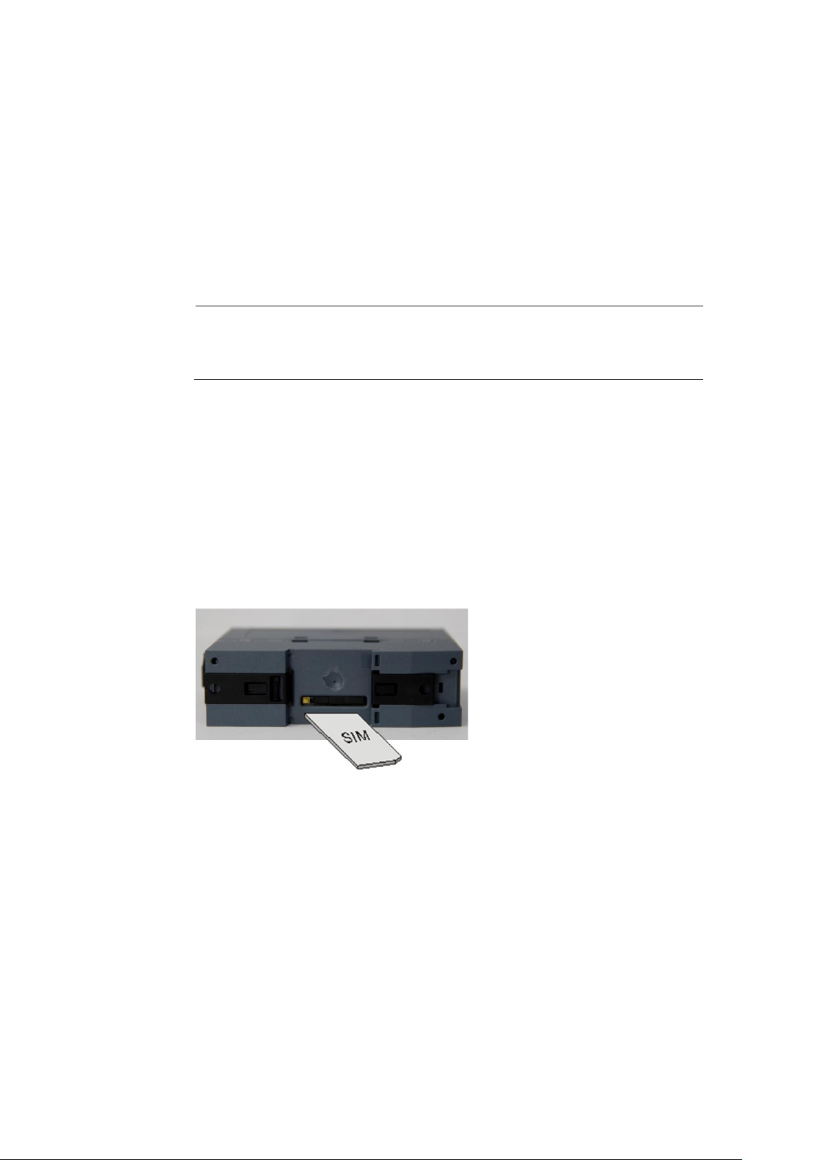
2
Notice
The device must be switched off when you insert or change the SIM card.
A plug-in SIM card (ID-000) is used.
Changing the SIM card
If you change the SIM card, please do not forget to update also the PIN number in
your application.
If you use a lot of SIM cards it can be helpful to set all PINs to the same PIN
number. You can do this i.e. by using a mobile phone. Please observe the security
requirements of your organization.
To insert the SIM card proceed as follows:
1. Make sure that the device is disconnected from the supply voltage.
Fehler! Verweisquelle konnte nicht gefunden werden. 13
Page 14
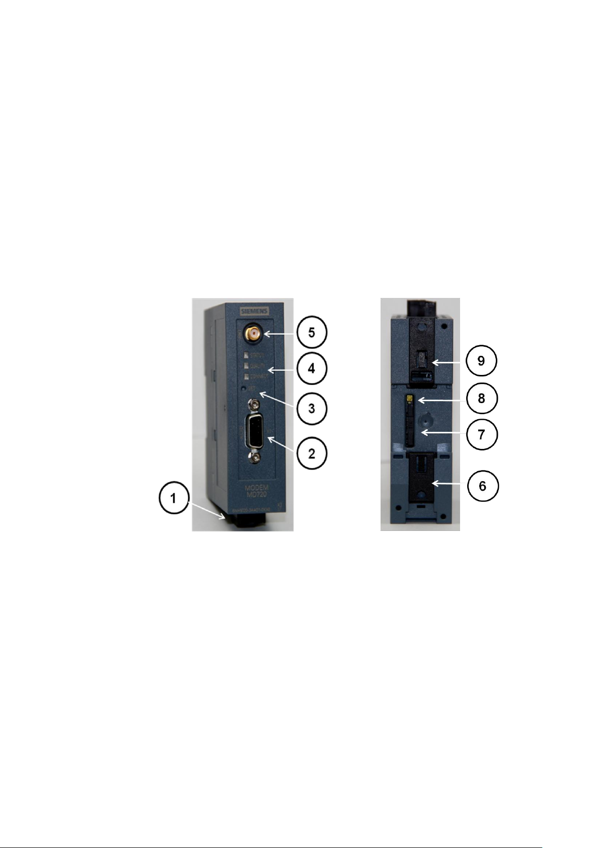
the device
3
1
Connector for supply voltage DC 24 V
2
Interface X1 (RS232) for the application or a service PC
3
SET button
4
LEDs: S (Status), Q (Quality), C (Connect)
5
Antenna connector
6, 9
Fixation for top rail mounting
7
SIM card holder tray
8
Button to access the SIM card
Connectors and LEDs
Fehler! Verweisquelle konnte nicht gefunden werden. 14
Page 15

Antenna
The antenna connector – SMA socket - is situated on the upper part of the front.
Impedance: approx. 50 Ohm
Caution
Please use only antennas of the MODEM MD720 accessory program. Other
antennas may disturb the product characteristics and may even cause defects.
Connectors for current supply
The screw terminals on the top of the device are for connecting the current supply:
24 V DC voltage (nominal), Ityp. 165mA at 24V. (Please also refer to chapter 7
Technical Data.) Both screw terminals on the left (24V) are internally connected,
see Fehler! Verweisquelle konnte nicht gefunden werden.. Both screw
terminals on the right (0V) are internally connected.
Connecting the device and switching on the device
.
Switching on
The devices switch on as soon as the operating voltage is supplied.
Functions of the LEDs
The MODEM MD720 has three LEDs, which are used to indicate the device
status. The function of the LEDs is different in terminal and OPC Mode. You will
find the explanation of the function
● in Terminal Mode in chapter 4.3 Functions of the LEDs in Terminal Mode and
● in OPC Mode in chapter 5.3 Functions of the LEDs in OPC Mode.
Serial interface X1
For data transmission:
Connect the application (e.g. machine, vending machine, sensor, computer) with
the interface X1 of the MODEM MD720. To connect, use a RS-232 cable.
If the application has a different interface, e.g. CAN, PPI cable or a different
industry bus, a commercially available interface converter can be connected
between it and the MODEM MD720.
OR
Fehler! Verweisquelle konnte nicht gefunden werden. 15
Page 16

Connecting the device and switching on the device
For configuration and service:
Connect the service PC via its serial interface (COM port). To connect, use a RS232 cable.
16 Fehler! Verweisquelle konnte nicht gefunden werden.
Page 17

The SET button
Pushing the SET button
LED Status
Function
during operation for less
than 2 seconds
The LED „S“ (Status)
begins to light
Dump of current
settings and values
issued via the RS232
interface
during operation for 2-4
seconds
The LED „Q“ (Quality)
begins to light
Service mode to
download a new
firmware
during operation for more
than 4 seconds
Die LED „C“
(Connect) begins to
light
Load factory settings
By pushing the SET button for a certain period of time, you can configure the
device or activate different service modes.
Connecting the device and switching on the device
Top-hat rail mounting
The MODEM MD720 is suitable for top-hat rail mounting on DIN EN 50022 rails. A
corresponding bracket can be found at the rear of the device.
Fehler! Verweisquelle konnte nicht gefunden werden. 17
Page 18

Connecting the device and switching on the device
18 Fehler! Verweisquelle konnte nicht gefunden werden.
Page 19

4
In the Terminal Mode the MODEM MD720 operates like a GSM modem, which is
controlled by AT commands.
Supported are
incoming and outgoing GSM data connections with 9600 bps with modems
being connected to the GSM network, the ISDN or the analogue telephone
network,
sending of SMS (Short Message Service).
4.1 Terminal mode activation
Terminal mode is the factory default setting
The MODEM MD720 supports two fundamental operation modes:
Terminal Mode,
OPC Mode.
The MODEM MD720 is delivered by the factory with activated Terminal Mode.
Switching from OPC Mode into the Terminal Mode
If it is necessary to switch a manually the MODEM MD720 from OPC Mode into
the Terminal Mode, you will find the instructions for this in the chapter Switching
between Terminal mode and OPC Mode.
Fehler! Verweisquelle konnte nicht gefunden werden. 19
Page 20

MODEM MD720 in Terminal Mode
LED
Status
Meaning
S, Q, C
combined
Fast lighting in sequence
Boot procedure
Synchronous slow blinking
Service mode
Slow lighting in sequence
Update
Synchronous fast blinking
Error
S (Status)
Blinks slowly
Device waiting for PIN input
Blinks fast
PIN error / SIM error
Q (Quality)
Blinks slowly
Booking into GSM network
1x intermittent blinking
Field strength not sufficient
2x intermittent blinking
Field strength sufficient
3x intermittent blinking
Field strength medium
ON permanently
Field strength high
OFF
Waiting for PIN input
C (Connect)
Blinks
Terminal mode active
4.2 Operating requirements in Terminal Mode: GPRS
subscriber contract
To use the MODEM MD720 in Terminal Mode it is required:
SIM card of a GSM network operator including CSD data service 9600 Bit/s
and an extra telephone number for data calls,
Availability of a GSM network.
4.3 Functions of the LEDs in Terminal Mode
The device has 3 LEDs, which indicates the current operation status:
S (Status) Q (Quality) C (Connect)
20 Fehler! Verweisquelle konnte nicht gefunden werden.
Blinks slowly: 1 time each second
Blinks fast: 4 times each second
Page 21

4.4 Terminal mode operation
To operate the device the PIN (PIN = Personnel Identification Number) of the
inserted SIM card must be known. In the Terminal Mode the PIN is not stored in
the MODEM MD720. The PIN must be set again every time the device is turnedon.
● The PIN is set by AT commands.
If you use a PIN-less SIM card the PIN request is skipped.
Control by the application
Usually the application or the application software, which you execute on a
connected computer, will control the MODEM MD720. So wits, the commands to
establish or to disconnect a data connection via the GSM network, are given by the
application to the device. For this purpose the application and the device
communicates using AT commands, like other types of modems. The sending of
SMS is handled in the same way.
MODEM MD720 in Terminal Mode
Direct control using AT command
You can also enter manually AT commands to control the MODEM MD720. In this
case use any terminal program (Refer to Working with a terminal program.)
Or you write your own communication program which is adapted especially to your
purposes.
Enter the PIN first
Please enter the PIN first before any other AT commands. Until a PIN has been
entered most AT commands will be answered with ERROR.
Fehler! Verweisquelle konnte nicht gefunden werden. 21
Page 22

MODEM MD720 in Terminal Mode
4.5 Entering AT commands
The MODEM MD720 is controlled by AT commands, which are entered either by
the connected application or manually by terminal program.
Working with a terminal program
To be able to control the device directly via AT commands, use a terminal program,
e.g. HyperTerminal.
Note the following settings:
Make the connection: COM port to which the device is connected
Speed: 19200 Bit/s
Data bits: 8
Parity: No
Stop bits: 1
Duplex: Full
PIN in Terminal-Mode
Enter the PIN
If the LED S blinks slowly (1 time each second), the MODEM MD720 waits for a
PIN entry.
In Terminal-Mode the PIN need to be entered using the AT command AT+CPIN.
Example:
The number of permitted trial to enter the PIN is limited by the SIM card.
Command: at+cpin="0000“ // Input incl. “ “
Response: OK
Normally three attempts are allowed, i.e. you may enter two times back-to-back a
wrong PIN, at the third attempt the right PIN must be entered, otherwise the SIM
will be blocked. In this case the SIM card can only be unblocked by entering the
PUK.
22 Fehler! Verweisquelle konnte nicht gefunden werden.
Page 23

The LED S (status) blinks fast
If the modem blinks fast (4 times each second), either the SIM card was not
detected correctly or the SIM card is PUK-blocked, because a wrong PIN has been
entered too often.
Please check, if the SIM card is inserted correctly (see chapter 2 Inserting the SIM
card).
Please check, if the SIM card is PUK-blocked. Insert the SIM card into a common
mobile phone. The mobile phone will display, if the SIM card is PUK-blocked. If the
SIM card is PUK-blocked, please enter the PUK and then a PIN. You can use a
common mobile phone to do this.
Before you enter again the SIM card into the MODEM MD720, please investigate
why the SIM card has been PUK-blocked: Which PIN have you entered or which
PIN has your application sent to the MODEM MD720?
Changing the SIM card
MODEM MD720 in Terminal Mode
If you change the SIM card, please do not forget to update also the PIN number in
your application.
If you use a lot of SIM cards it can be helpful to set all PINs to the same PIN
number. You can do this i.e. by using a mobile phone. Please observe the security
requirements of your organization.
PIN-less SIM cards
The device operates also with SIM cards, which PIN check is deactivated. In this
case the PIN check is skipped and the device will immediately try to attach the
GSM network.
Fehler! Verweisquelle konnte nicht gefunden werden. 23
Page 24

MODEM MD720 in Terminal Mode
4.6 Use AT commands
Syntax
The AT command language is a standard for controlling modems. It is lineorientated. Each command line begins with AT (for ATtention), followed by the
actual command, and ends with (Enter key).
Example: ATD444444¬
means: dial (D for Dial) 444444
There are only two exceptions to this rule:
The command +++ to switch to Command Phase (see below) and the command
A/ with which the last command line is repeated.
Command phase, Transparent phase
The device accepts AT commands only when it is in Command Phase.
It is in Command Phase,
when there is no active connection,
when the sequence Pause +++ has been entered during a connection.
The device does not accept AT commands when it is in Transparent Phase.
It is in Transparent Phase,
when there is an active connection,
when the device has been switched to Command Mode during an active
connection with +++ and then switched back to Transparent Mode with ATO.
Enabling/disabling local echo
To see your entries on the screen, you may have to enable the local data echo. To do
so, enter the following command: ATE1
To disable the local data echo, enter the following command: ATE0
24 Fehler! Verweisquelle konnte nicht gefunden werden.
Page 25

Enter the PIN
Command: at+cpin="0000“
Response: OK
Network-Status request
Command: at+creg?
Response: +CREG: 0,1
Firmware Version request
Command: ati3
Response: SIE3171 MODEM MD720 V.1.7.00 19.05.2006
MODEM MD720 in Terminal Mode
CSD call outgoing:
Command: atd0123456789
Response: CONNECT
CSD call incoming:
Response: RING
Command: ata
Response: CONNECT
Sending SMS:
Command: at+cmgf=1
Response: OK
Command: at+cmgs="phonenumber",145
Command: >Text of the SMS max. 160 characters; End and sending with Strg-
Z
Response: +CMGS: 251 // value is an example
OK
Fehler! Verweisquelle konnte nicht gefunden werden. 25
Page 26
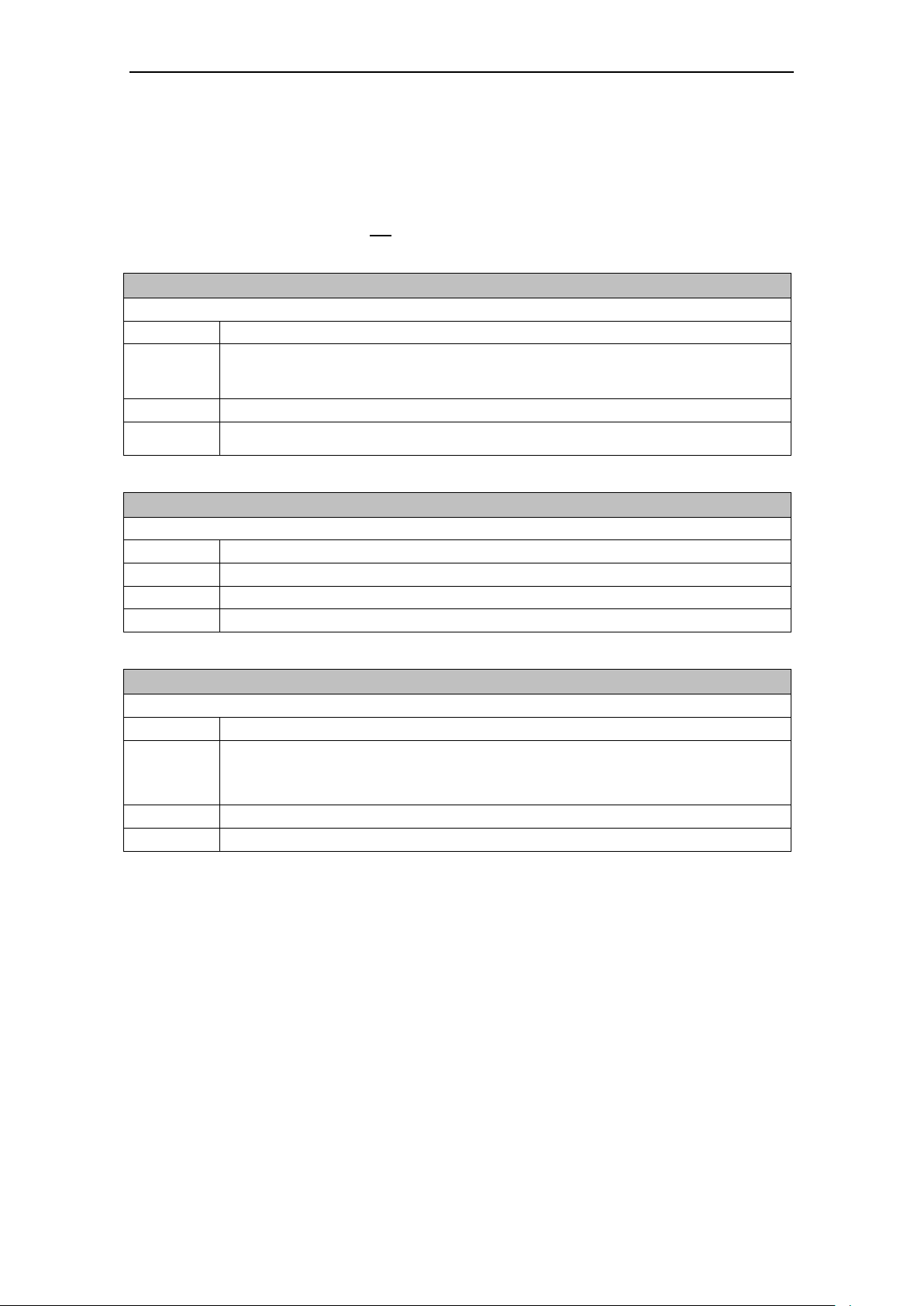
MODEM MD720 in Terminal Mode
+++
Switch from data mode to command mode
Execute command
Command:
+++
Response:
This command is only available during data calls. The +++ characters sequence causes
to cancel de data flow over the AT interface and switch to command mode. This allows to
enter AT commands while maintaining the data connection to the remote device.
Parameter:
-
Notice:
To return to data mode, use the ATO command
Line does not need to end with terminating character, i.e. <CR><LF>
A/
Repeat previous command line
Executive command
Command:
A/
Response:
Depend on the previous command
Parameter:
-
Notice:
Line does not need to end with terminating character, i.e. <CR><LF>
ATA
Answer a call
Executive command
Command:
ATA
Response:
CONNECT[<text>] Data connection established
OK Voice connection established or if cancellation of the
command
NO CARRIER Response if no connection
Parameter:
-
Notice:
See ATX for setup of the CONNECT message.
4.7 Supported AT commands in Terminal Mode
All AT commands being not listed below will be answered with OK by the device,
but the command will not be executed.
26 Fehler! Verweisquelle konnte nicht gefunden werden.
Page 27
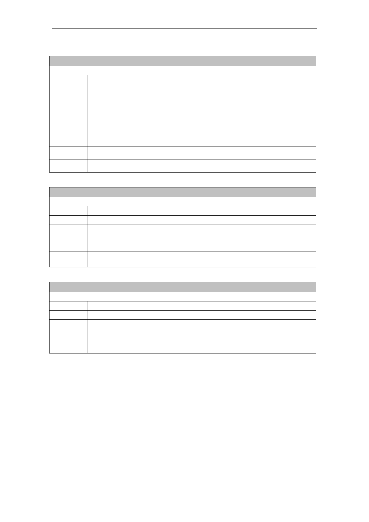
MODEM MD720 in Terminal Mode
ATD
Mobile originated Call to dial a number
Executive command
Command:
ATD[<n>]
Response:
The connection cannot be established:
NO DIALTONE
BUSY
NO CARRIER
NO ANSWER
Data connection successfully connected:
CONNECT[<text>]
Parameter:
<n>:
String of dialing digits and optionally V.25ter modifiers (dialing digits): 0-9, * , #, +, A, B, C
Notice:
-
ATE
Local Echo On/Off
Executive command
Command:
ATE[<value>]
Response:
OK
Parameter:
<value>:
0 Local Echo off
1 Local Echo on <Default>
Notice:
This setting determines whether or not the device echoes characters received from
application during command state
ATH
Disconnect existing connection
Executive command
Command:
ATH
Response:
OK
Parameter:
-
Notice:
On this command, all calls in progress are ended.
If a call is in progress, it is necessary to switch into the command phase by +++ before
entering commands.
Fehler! Verweisquelle konnte nicht gefunden werden. 27
Page 28
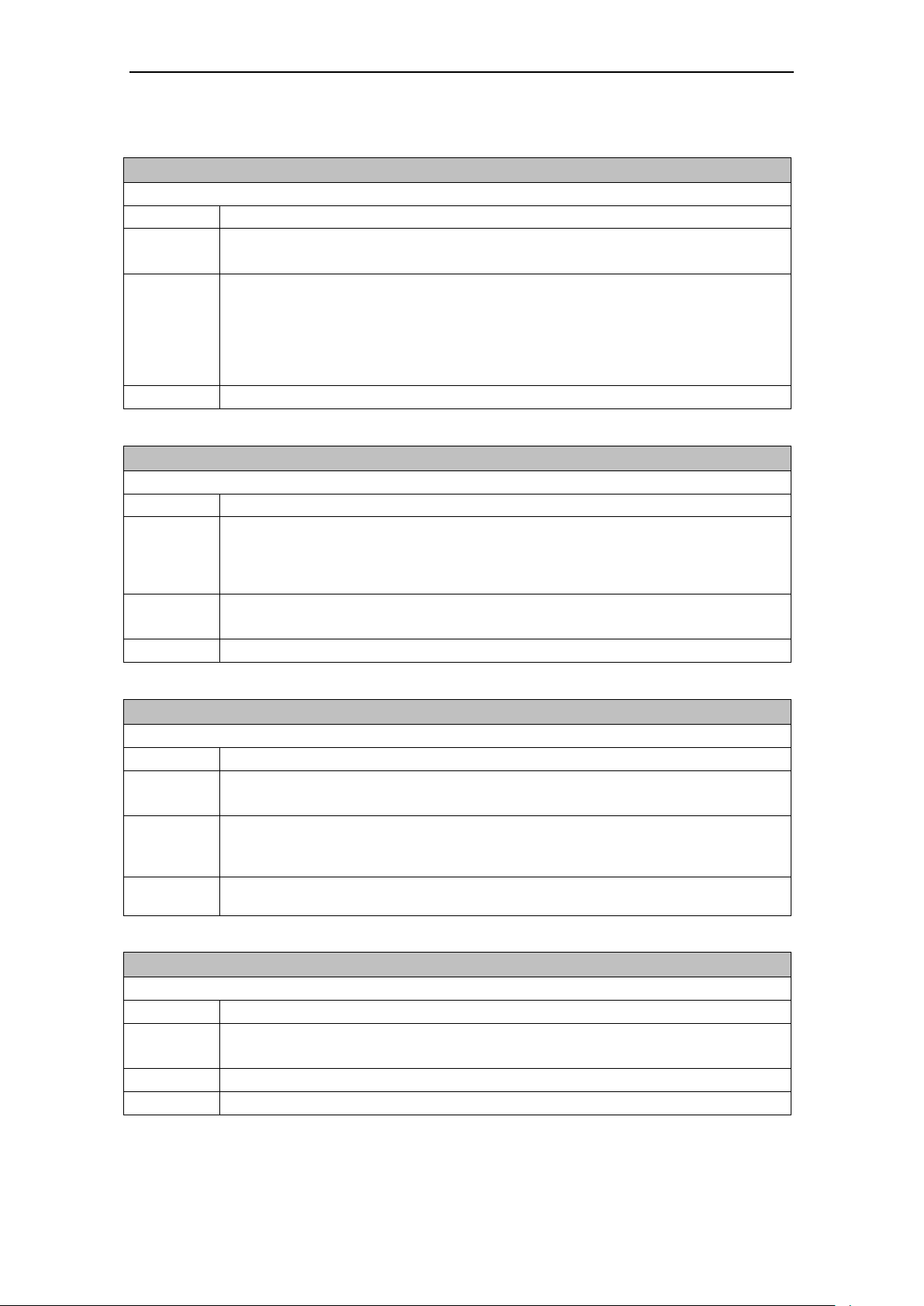
MODEM MD720 in Terminal Mode
ATI
Request identification information
Read command
Command:
ATI[<value>]
Response:
<text> (depends on <value>)
OK
Parameter:
<value>:
none: Product name and Firmware Version
0: Product name and Firmware Version
1: Product name, Interface, Mode
3: Product name and Firmware Version
Notice:
<text> may take more than one line
ATO
Switch from command mode to data mode
Executive command
Command:
ATO[n]
Response:
Device returns to data mode from command mode:
CONNECT <text>
If connection is not successfully resumed
NO CARRIER
Parameter:
<n>:
0 switch from command mode to data mode
Notice:
ATO corresponds to the +++ escape sequence.
ATQ
Set result code presentation mode
Executive command
Command:
ATQ[<n>]
Response:
OK (if <n> = 0)
Nothing (if <n> = 1)
Parameter:
<n>:
0: result codes transmitted by the device <Default>
1: no result code transmitted by the device
Notice:
Specifies whether or not the device transmits any result code to the application.
Information text transmitted in response is not affected by this setting.
ATS0?
Shows Automatic answering settings
Read command
Command:
ATS0?
Response:
<n>
OK
Parameter:
See ATS0=<n>
Notice:
-
28 Fehler! Verweisquelle konnte nicht gefunden werden.
Page 29

MODEM MD720 in Terminal Mode
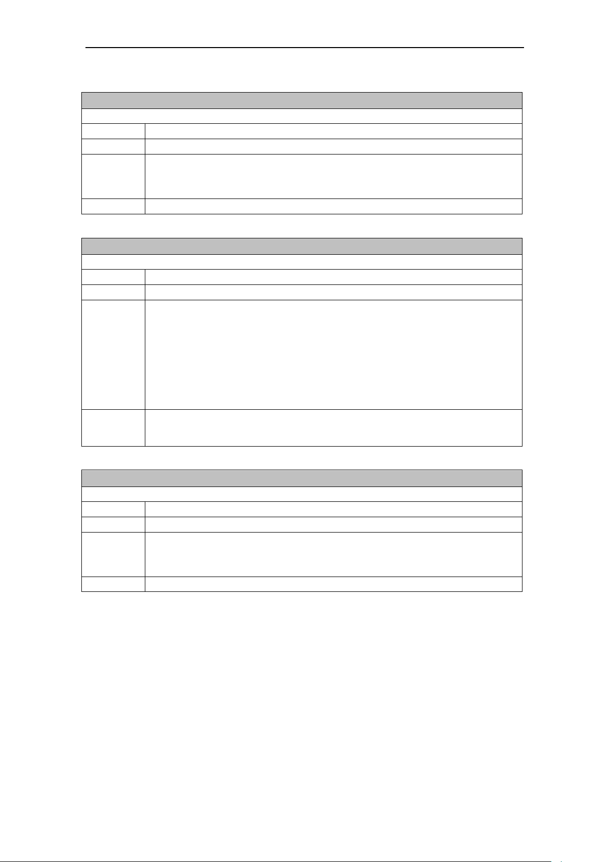
ATS0
Configures Automatic answering
Executive command
Command:
ATS0=<n>
Response:
OK
Parameter:
<n>:
0: automatic answering deactivated <Default>
1-255: number of rings before automatically answering
Notice:
GSM networks usually generate only 8-12 RING. If S0 is set to a higher value, calls are
eventually not being answered.
ATV
Set result code format mode
Executive command
Command:
ATV[<value>]
Response:
0 When numeric mode is activated
OK When verbose mode is activated
Parameter:
<value>:
0 Information <text><CR><LF>
Result Code (short format): <numeric code><CR>
1 Information <CR><LF><text><CR><LF>
Result Code (long format): <CR><LF><verbose code><CR>
<Default>
Notice:
This parameter setting determines the contents of the header and trailer transmitted with
result codes and information responses.
Result codes numeric or verbose:
OK 0 Command executed, no error, Restart executed
CONNECT 1 Connection established
RING 2 Ring detected
NO CARRIER 3 Connection not established or interrupted
ERROR 4 Command not valid
NO DIALTONE 6 No dialtone, dialing not possible, wrong mode
BUSY 7 Remote station busy
CONNECT 2400/RLP 1 Connect at 2400 bps and Radio Link Protocol
CONNECT 4800/RLP 1 Connect at 4800 bps and Radio Link Protocol
CONNECT 9600/RLP 1 Connect at 9600 bps and Radio Link Protocol
Fehler! Verweisquelle konnte nicht gefunden werden. 29
Page 30
MODEM MD720 in Terminal Mode
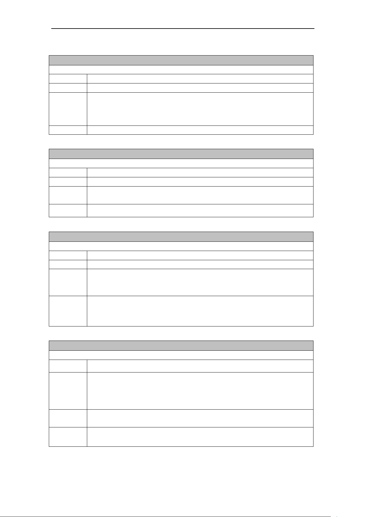
AT\Q
Hardware Flow Control on/off
Executive command
Command:
AT\Q<n>
Response
OK
Parameter:
<n>:
0: Hardware Flow Control (RTS/CTS) off
3: Hardware Flow Control (RTS/CTS) on
Notice:
-
ATX
Set CONNECT result code Format und Call monitoring
Executive command
Command:
ATX[<value>]
Response:
OK
Parameter:
<value>:
0 : CONNECT result code only returned, dial tone and busy detection are both
disabled <Default>
1 : CONNECT<text> result code only returned, dial tone and busy detection are
both disabled
2 : same as 1
3 : same as 1
4 : same as 1
Notice:
The term “tone” is used in analogue telephone networks. The status “No dialtone” will
usually not appear, as soon as the device is booked into a GSM network. A Busy
message will be transmitted.
AT&C
AT&C Set circuit Data Carrier Detect (DCD) function mode
Executive command
Command:
AT&C[<value>]
Response:
OK
Parameter:
<value>:
0 : DCD line is always ON
1 : DCD line is ON in the presence of data carrier only. <Default>
Notice:
-
30 Fehler! Verweisquelle konnte nicht gefunden werden.
Page 31
MODEM MD720 in Terminal Mode
AT&D
Set circuit Data Terminal Ready (DTR) function mode
Executive command
Command:
AT&D[<value>]
Response:
OK
Parameter:
<value>:
0: Device ignores status on DTR. <Default>
2: ON->OFF on DTR: Disconnect call, change to command mode. During state
DTR = OFF is auto-answer off.
Notice:
-
AT&F
Restore manufactory configuration
Executive command
Command:
AT&F
Response:
OK
Parameter:
<value>:
0: Restore parameters to manufactory values
Notice:
Restores the configuration of manufacturer of the following commands: ATE, ATQ, ATV,
ATX, AT&C, AT&D, AT\Q and ATS0.
AT&W
Save stored profile
Executive command
Command:
AT&W<n>
Response:
OK
Parameter:
<n>:
None Saving in Profile 0
0 Saving in Profile 0
Notice:
This command saves the current configuration in a non volatile memory of the commands
ATE, ATQ, ATV, ATX, AT&C, AT&D, AT\Q and ATS0. The configuration can be reloaded
with ATZ. Before the first saving the profile is the same as the default configuration.
See also AT&V.
AT&V
Display current configuration
Executive command
Command:
AT&V[<value>]
Response:
ACTIVE PROFILE:
<current configuration>
OK
Parameter:
<value>:
0: only active profile
Notice:
The configuration is a text string on multiple lines as shown in the example below. As it is
dependant on the manufactory and user set-up, it is impossible to list the exact number of
information given.
Fehler! Verweisquelle konnte nicht gefunden werden. 31
Page 32

MODEM MD720 in Terminal Mode
AT+CCLK
Clock
Test
Command:
+CCLK=?
Response:
OK
Read command
Command:
+CCLK?
Response:
+CCLK: <time>
Executive command
Command:
AT+CCLK=<time>
Response:
OK
+CME ERROR: <err>
Parameter:
<time>:
String variable; the format is "yy/MM/dd,hh:mm:sszz", with
yy: Year
MM: Month
dd: Day
mm: Minute
ss: Second
zz: Time zone, gives the difference between the local time and GMT, given in
quarters of an hour; the range of values is -47…+48. Example: 6th of may,
1994, 22:10:00 GMT+2 hours corresponds to "94/05/06,22:10:00+08"
Notice:
-
32 Fehler! Verweisquelle konnte nicht gefunden werden.
Page 33

MODEM MD720 in Terminal Mode
AT+CRLP
Radio link protocol
Test
Command:
+CRLP=?
Response:
+CRLP: (list of supported <iws>s),(list of supported <mws>s),
(list of supported <T1>s),(list of supported <N2>s),<ver1>
,(list of supported <T4>s)
Read command
Command:
+CRLP?
Response:
+CRLP: <iws>,<mws>,<T1>,<N2>,<ver1>,<T4>
Executive command
Command:
AT+CRLP=<iws>[,<mws>[,<T1>[,<N2>[,<ver>[,<T4>]]]]]
Response:
OK
Parameter:
<ver>: RLP version number as Integer variable; Version number 0 indicates “RLP
version indication not available”
<iws>: Window size IWF to MS
<mws>: Window size MS to IWF
<T1>: Acknowledge timer T1
<N2>: Retransmission attempts N2
<T4>: Re-sequencing period T4 as Integer variable
Notice:
Default values and value ranges depend on RLP Version; refer GSM 04.22 [18].
T1 and T4 are in units of 10 ms.
Fehler! Verweisquelle konnte nicht gefunden werden. 33
Page 34

MODEM MD720 in Terminal Mode
AT+CPIN
Enter PIN
Test
Command:
AT+CPIN=?
Response:
OK
Read command
Command:
AT+CPIN?
Response:
+CPIN: <code>
Executive command
Command:
AT+CPIN=<pin> [,<newpin>]
Response:
OK
Parameter:
<code>:
Values reserved by this device:
READY Device is not pending for any password
SIM PIN Device is waiting SIM PIN to be given
SIM PUK Device is waiting SIM PUK to be given. Also, a second pin, <newpin>, is
used to replace the old pin in the SIM and should thus be supplied
SIM PIN2 Device is waiting SIM PIN2 to be given (this <code> is recommended to
be returned only when the last executed command resulted in PIN2
authentication failure (i.e. +CME ERROR: 17); if PIN2 is not entered right
after the failure, it is recommended that ME does not block its operation)
SIM PUK2 Device is waiting SIM PUK2 to be given (this <code> is recommended to
be returned only when the last executed command resulted in PUK2
authentication failure (i.e. +CME ERROR: 18); if PUK2 and new PIN2 are
not entered right after the failure, it is recommended that ME does not
block its operation). Also, a second pin, <newpin>, is used to replace the
old pin in the SIM and should thus be supplied
PH-NET PIN ME is waiting personalization password to be given
<pin>, <newpin>:
String type value (8 characters max.)
Notice:
-
34 Fehler! Verweisquelle konnte nicht gefunden werden.
Page 35

MODEM MD720 in Terminal Mode
AT+CSQ
Check Signal Quality
Test
Command:
AT+CSQ=?
Response:
+CSQ: (list of supported <rssi>s),(list of supported <ber>s)
OK
Response:
Command:
AT+CSQ
Response:
+CSQ: <rssi>,<ber>
OK
Parameter:
<rssi>:
0 -113 dBm or less
1 -111 dBm
2...30 -109... -53 dBm
31 -51 dBm or greater
99 not known or not detectable
<ber>:
0...7 as RXQUAL values in the table in GSM 05.08 [20] subclause 8.2.4
99 not known or not detectable
Notice:
The read command (AT+CSQ?) returns an error.
AT+CGSN
Request product serial number identification (IMEI) identical to GSN
Test
Command:
AT+CGSN=?
Response:
OK
Read command
Command:
AT+CGSN
Response:
<sn> (identification text for determination of the individual device)
OK
Parameter:
-
Notice:
-
Fehler! Verweisquelle konnte nicht gefunden werden. 35
Page 36

MODEM MD720 in Terminal Mode
AT+CGDCONT Define PDP context
Test
Command:
AT+CGDCONT=?
Response:
+CGDCONT: (Range of supported <cid>s), <PDP_type>,,,(List of supported
<d_comp>s), (List of supported <h_comp>s)
Read command
Command:
AT+CGDCONT?
Response:
If +CGDCONT is set:
+CGDCONT: <cid>, <PDP_type>, <APN>,<PDP_addr>, <d_comp>, <h_comp>
If +CGDCONT is not set:
OK
Executive command
Command:
+CGDCONT=<cid> ,<PDP_type> ,<APN> ,<PDP_addr> ,<d_comp> ,<h_comp>
Response:
OK
Parameter:
<cid>: (Local) context identification parameter
<PDP_type>: Packet Data Protocol type
A string parameter which specifies the type of packet data protocol. Only IP Internet
Protocol - IETF STD 5) is supported.
<APN>: Access Point Name
A string parameter which is a logical name that is used to select the GGSN or the external
packet data network.
<PDP_address>:
A string parameter that identifies the MT in the address space applicable to the PDP. As
only IP is currently supported, it shall be an IP address.
If the value is null (“0.0.0.0” or 0), then a value may be provided by the TE during the PDP
startup procedure or, failing that, a dynamic address will be requested.
The read form of the command will continue to return the null string even if an address
has been allocated during the PDP startup procedure. The allocated address may be
read using the +CGPADDR command.
<d_comp>:
A numeric parameter that controls PDP data compression.
0: off (default and only value supported)
<h_comp>:
A numeric parameter that controls PDP header compression
0: off (default and only value supported)
<pd1>, … <pdN>:
Zero to N string parameters whose meanings are specific to the <PDP_type>
Notice:
The execute command specifies PDP context parameter values for a PDP context
identified by the (local) context identification parameter, <cid>. The number of PDP
contexts that may be in a defined state at the same time is given by the range returned by
the test command.
A special form of the set command, +CGDCONT= <cid> causes the values for context
number <cid> to become undefined.
36 Fehler! Verweisquelle konnte nicht gefunden werden.
Page 37

MODEM MD720 in Terminal Mode
AT+CGATT GPRS Attach or Detach
Test
Command:
AT+CGATT=?
Response:
+CGATT: (list of supported <state>s)
Read command
Command:
AT+CGATT?
Response:
+CGATT: <state>
Executive command
Command:
+CGATT=<state>
Response:
OK
Parameter:
<state>:
Indicates the state of GPRS attachment
0: detached
1: attached
Notice:
-
AT+CIMI
Request international subscriber identity
Test
Command:
AT+CIMI=?
Response:
OK
Read command
Command:
AT+CIMI
Response:
<IMSI> (International Mobile Subscriber Identify)
OK
Parameter:
-
Notice:
-
Fehler! Verweisquelle konnte nicht gefunden werden. 37
Page 38

MODEM MD720 in Terminal Mode
AT+CPAS
Phone activity status
Test
Command:
AT+CPAS=?
Response:
+CPAS: (list of supported <pas>s)
OK
Read command
Command:
AT+CPAS
Response:
+CPAS: <pas>
OK
Parameter:
<pas>:
0 ready (device allows commands from application)
1 unavailable (device does not allow commands from application)
2 unknown (device is not guaranteed to respond to instructions)
3 ringing (device is ready for commands from application, but the ringer is active)
4 call in progress (device is ready for commands from application, but a call is in
progress)
Notice:
-
38 Fehler! Verweisquelle konnte nicht gefunden werden.
Page 39

MODEM MD720 in Terminal Mode
AT+CPMS
Preferred Message Storage
Test
Command:
AT+CPMS=?
Response:
+CPMS: (list of supported <mem1>s),(list of supported <mem2>s),(list of supported
<mem3>s),
OK
Read command
Command:
AT+CPMS?
Response:
+CPMS: <mem1>,<used1>,<total1>,<mem2>,<used2>,<total2>,<mem3>,
<used3>,<total3>
OK
Executive command
Command:
AT+CPMS= <mem1>,<mem2>,<mem3>
Response:
+CPMS: <used1>,<total1>,<used2>,<total2>,<used3>,<total3>
OK
Parameter:
The executive command selects the SMS storage <mem<x>>, being used to read, write,
etc.
<mem1>
Memory to be used for listing, reading and deleting of messages:
“SM” Message storage on SIM card
“ME” Message storage on device
“MT” Sum of message storage on SIM card and device
<mem2>
Memory to be used for writing and sending of messages:
“SM” Message storage on SIM card
“ME” Message storage on device
“MT” Sum of message storage on SIM card and device
<mem3>
Memory to be used for storage of received messages, if the routing to the connected
application is not possible. Refer to command AT+CNMI with parameter <mt>=2
“SM” Message storage on SIM card
“MT” Sum of message storage on SIM card and device
<usedx>
Number of messages currently stored in <memx>.
<totalx>
Number of messages currently which can be stored in<memx>.
Notice:
Example:
AT+CPMS=? +CPMS: ("ME","SM","MT")
OK
AT+CPMS? +CPMS: "ME",0,100
OK
AT+CPMS="ME" +CPMS: 0,100
OK
Until firmware version 1.6 inclusive, only the message storage “MT could be selected for
<mem3>.
Fehler! Verweisquelle konnte nicht gefunden werden. 39
Page 40

MODEM MD720 in Terminal Mode
AT+CNUM
Subscriber number
Test
Command:
AT+CNUM=?
Response:
OK
Executive command
Command:
AT+CNUM
Response:
+CNUM: [<alpha1>],<number1>,<type1>[,<speed>,<service>[,<itc>]]
[<CR><LF>+CNUM: [<alpha2>],<number2>,<type2>[,<speed>,<service>
[,<itc>]]
[...]]
OK
Parameter:
<alpha>:
optional alphanumeric string associated with <number>; used character set should be the
one selected with command Select TE Character Set +CSCS
<number>:
string type phone number of format specified by <type>
<type>:
type of address octet in integer format (refer GSM 04.08 [8] subclause 10.5.4.7)
<speed>:
<service>:
service related to the phone number
0: asynchronous modem
1: synchronous modem
2: PAD Access (asynchronous)
3: Packet Access (synchronous)
4: voice
5: fax
also all other values below 128 are reserved by the present document
<itc>:
information transfer capability
0: 3.1kHz
1: UDI
Notice:
Action command returns the MSISDNs related to the subscriber (this information can be
stored in the SIM or in the ME)
The Read Command (AT+CNUM?) returns an error
Example:
AT+CNUM +CNUM: "TEL","0612345678",129
+CNUM: "","",255
+CNUM: "","",255
+CNUM: "","",255
OK
40 Fehler! Verweisquelle konnte nicht gefunden werden.
Page 41

MODEM MD720 in Terminal Mode
AT+CBST
Select bearer service type
Read command
Command:
AT+CBST=?
Response:
+CBST: (list of supported <speed>s),(list of supported <name>s),(list of supported <ce>s)
OK
Executive command
Command:
AT+CBST=[<speed> [,<name>[,<ce>]]]
Response:
OK
Parameter:
<speed>:
4 2400 bps (V.22bis)
6 4800 bps (V.32)
7 9600 bps (V.32)
68 2400 bps (V.110 or X.31 flag stuffing)
70 4800 bps (V.110 or X.31 flag stuffing)
71 9600 bps (V.110 or X.31 flag stuffing)
<name>:
0 data circuit asynchronous (UDI or 3.1 kHz modem)
1 Not supported
<ce>:
0 transparent
1 non-transparent
Notice:
Set command selects the bearer service <name> with data rate <speed>, and the
connection element <ce> to be used when data calls are originated.
AT+CMGD
Delete a SMS
Test
Command:
AT+CMGD=?
Response:
+CMS ERROR: <err>
Read command
Command:
AT+CMGD?
Response:
+CMS ERROR: <err>
Executive command
Command:
+CMGD=<index>
Response:
OK or +CMS ERROR: <err>
Parameter:
<index>
1 – n Memory location on the SIM card; n depends on the memory capacity of the
SIM card
<err> Error code
Notice:
-
Fehler! Verweisquelle konnte nicht gefunden werden. 41
Page 42

MODEM MD720 in Terminal Mode
AT+CMGF
Select SMS message format
Test
Command:
AT+CMGF=?
Response:
+CMGF: (list of supported <mode>s)
OK
Read command
Command:
AT+CMGF?
Response:
+CMGF: <mode>
OK
Executive command
Command:
AT+CMGF=[<mode>]
Response:
OK
Parameter:
<mode>:
0 PDU mode
1 Text mode
Notice:
-
42 Fehler! Verweisquelle konnte nicht gefunden werden.
Page 43

MODEM MD720 in Terminal Mode
AT+ CMGL
List SMS messages from preferred storage
Test
Command:
AT+CMGL=?
Response:
+CMGL: (list of supported <stat>s)
OK
Executive command
Command:
AT+CMGL[=<stat>]
Response:
In text mode (+CMGF=1) and successfully executed command and SMS-SUBMITs
and/or SMS-DELIVERs:
If <stat> = "REC READ" or "REC UNREAD"
+CMGL: <index>,<stat>,<oa/da>,<scts>,<length>
<CR><LF><data><CR><LF>
[+CMGL: <index>,<stat>,<oa/da>,<scts>,<length><CR><LF><data>
<CR><LF>[...]]
If <stat> = "STO UNSENT" or "STO SENT"
+CMGL: <index>,<stat>,<oa/da>,<length>
<CR><LF><data><CR><LF>
[+CMGL: <index>,<stat>,<oa/da>,<length><CR><LF><data>
<CR><LF>[...]]
In other cases:
+CMS ERROR: <err>
In PDU mode (+CMGF=0) and successfully executed command:
[+CMGL: <index>,<stat>,[<alpha>],<length><CR><LF><pdu>
[<CR><LF>+CMGL:<index>,<stat>,[<alpha>],<length><CR><LF><pdu>
[...]]]
OK
Fehler! Verweisquelle konnte nicht gefunden werden. 43
Page 44
MODEM MD720 in Terminal Mode
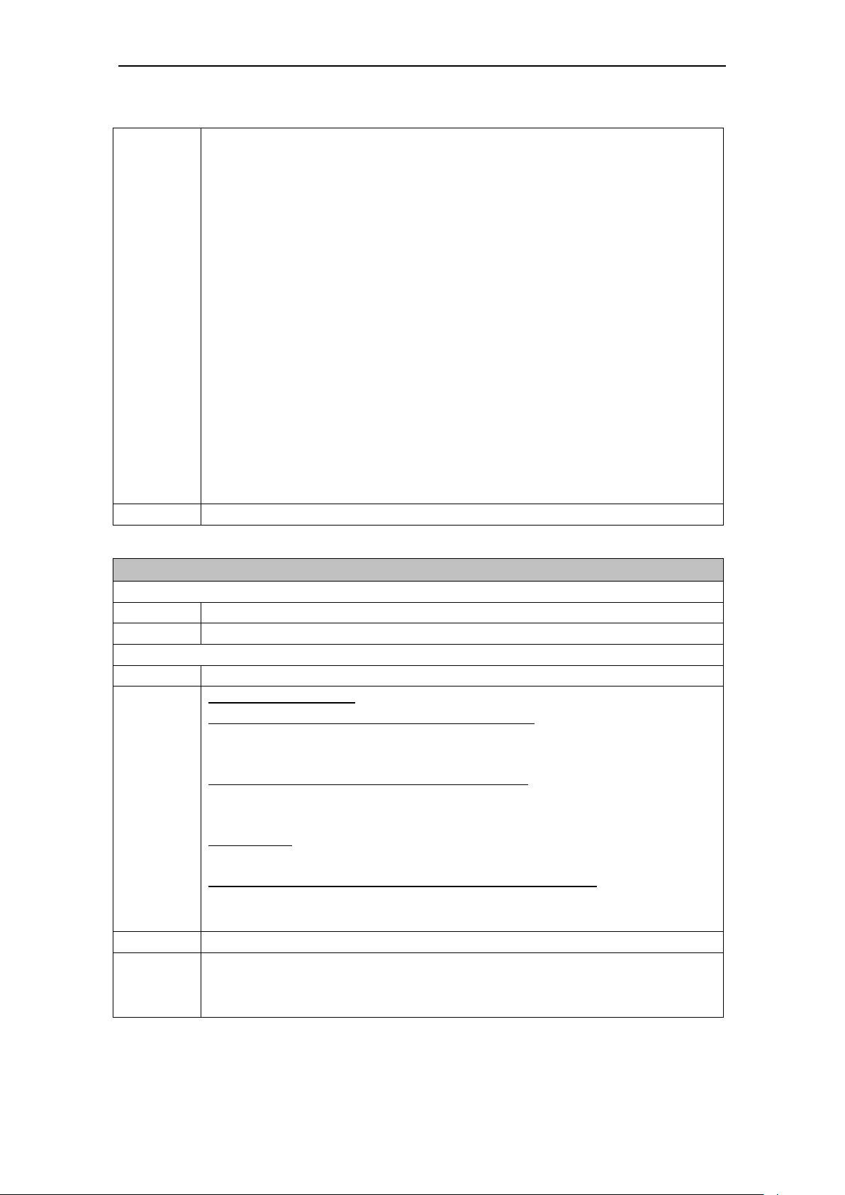
Parameter:
<index>
integer type; value in the range of location numbers supported by the associated memory
<stat>
integer type (default 0: "REC UNREAD"); indicates the status of message in memory;
defined values:
0 "REC UNREAD" received unread message (i.e. new message)
1 "REC READ" received read message
2 "STO UNSENT" stored unsent message (only applicable to SMS)
3 "STO SENT" stored sent message (only applicable to SMS)
4 "ALL" all messages (only applicable to +CMGL command)
<oa/da>
GSM 03.40 TP-Originating-Address / TP-Destination-Address Address-Value field in
string format
<scts>
GSM 03.40 TP-Service-Centre-Time-Stamp in time-string format
<length>
integer type value indicating the length in characters of the message body <data>
<data>
GSM 03.40 TP-User-Data in text mode responses
Notice:
The execute command indicates the state <stat> of the preferred SMS storage <mem1>.
AT+CMGR
Read SMS message
Test
Command:
AT+CMGR=?
Response:
OK
Executive command
Command:
AT+CMGR=<index>
Response:
In text mode (+CMGF=1)
If command is executed successfully and SMS-DELIVER:
+CMGR: <stat>,<oa>,<scts>,<length>
<CR><LF><data><CR><LF>
If command is executed successfully and SMS-SUBMIT:
+CMGR: <stat>,<da>,<length>
<CR><LF><data><CR><LF>
In other cases:
+CMS ERROR: <err>
In PDU mode (+CMGF=0) and successfully performed command:
+CMGR: <stat>,[<alpha>],<length><CR><LF><pdu>
OK
Parameter:
Refer to +CMGL
Notice:
Execution command returns message with location value <index> from preferred
message storage <mem1>. Status of the message and entire message data unit <pdu> is
returned. If status of the message is 'received unread', status in the storage changes to
'received read'.
44 Fehler! Verweisquelle konnte nicht gefunden werden.
Page 45
MODEM MD720 in Terminal Mode
AT+CMGS
Sending SMS
Test
Command:
AT+CMGS=?
Response:
OK
Executive command
Command:
In text modus (+CMGF=1):
+CMGS=<da>,<toda><CR>
> text is entered<ctrl-Z/ESC>
In PDU mode (+CMGF=0):
AT+CMGS=<length><CR> enter PDU <ctrl-Z/ESC>
Response:
In text mode (+CMGF=1) and successful sending:
+CMGS: 0
If sending fails:
+CMS ERROR: <err>
In PDU mode (+CMGF=0) and successful sending:
+CMGS: <mr>[,<ackpdu>]
OK
Parameter:
<da>:
Enter phonenumber with “ “
<toda>:
145: Enter phone number incl. country code, e.g. +49xxxxx for Germany
129: Enter phone number without country code
<mr>:
TP-Message-Reference in integer format
<ackpdu>
RP-User-Data element of RP-ACK PDU; format is same as for <pdu> in case of SMS, but
without 3G TS 24.011 [6] SC address field and parameter shall be bounded by double
quote characters like a normal string type parameter
<length>
Integer type value indicating in the text mode (+CMGF=1) the length of the message body
<data> > (or <cdata>) in characters; or in PDU mode (+CMGF=0), the length of the actual
TP data unit in octets (i.e. the RP layer SMSC address octets are not counted in the
length)
Notice:
- The device shall send a four character sequence <CR><LF><greater_than><space>
(IRA 13, 10, 62, 32) after command line is terminated with <CR>; after that PDU can
be given from application to the device
- the DCD signal shall be in ON state while PDU is given
- the echoing of given characters back from the device is controlled by V.25ter echo
command E
- the PDU shall be hexadecimal format (similarly as specified for <pdu>) and given in
one line; the device converts this coding into the actual octets of PDU
- when the length octet of the SMSC address (given in the PDU) equals zero, the
SMSC address set with command Service Centre Address +CSCA is used; in this
case the SMSC Type-of-Address octet shall not be present in the PDU, i.e. TPDU
starts right after SMSC length octet
- sending can be cancelled by giving <ESC> character (IRA 27)
- <ctrl-Z> (IRA 26) must be used to indicate the ending of PDU
Fehler! Verweisquelle konnte nicht gefunden werden. 45
Page 46

MODEM MD720 in Terminal Mode
AT+CNMI
New SMS message indication
Test
Command:
AT+CNMI=?
Response:
+CNMI: (list of supported <mode>s), (list of supported <mt>s), (list of supported <bm>s),
(list of supported <ds>s), (list of supported <bfr>s) 2.
Read command
Command:
AT+CNMI?
Response:
+CNMI: <mode>,<mt>,<bm>,<ds>,<bfr>,OK
Executive command
Command:
AT+CNMI=[<mode>][,<mt>][,<bm>][,<ds>][,<bfr>]
Response:
OK
Parameter:
<mode>:
0: Buffer unsolicited result codes in the device. If device result code buffer is full,
indications can be buffered in some other place or the oldest indications may be
discarded and replaced with the new received indications.
1: Discard indication and reject new received message unsolicited result codes
when the link between the device and the connected application is reserved.
Otherwise forward them directly to the connected application.
2: Buffer unsolicited result codes in the device when the link between the device
and the connected application is reserved (e.g. in on-line data mode) and flush
them to the connected application after reservation. Otherwise forward them
directly to the connected application.
3: Not supported
<mt>:
0: No SMS-DELIVER indications are routed to the connected application.
1: If SMS-DELIVER is stored into device, indication of the memory location is
routed to the connected application using unsolicited result code +CMTI:
<mem>,<index>
<bm>:
0: No CBM indications are routed to the connected application.
<ds>:
0: No SMS-STATUS-REPORTs are routed to the connected application.
<bfr>:
0: The buffered notifications are sent.
Notice
-
46 Fehler! Verweisquelle konnte nicht gefunden werden.
Page 47

MODEM MD720 in Terminal Mode
AT+CREG
Network registration
Test
Command:
AT+CREG=?
Response:
+CREG: (list of supported <n>s)
OK
Read command
Command:
AT+CREG?
Response:
+CREG: <n>,<stat>[,<lac>,<ci>]
OK
Executive command
Command:
AT+CREG=<n>,<stat>
Response:
OK
Parameter:
<n>:
0: disable network registration unsolicited result code
1: enable network registration unsolicited result code +CREG: <stat>
2: enable network registration and location information unsolicited result code
+CREG: <stat>[,<lac>,<ci>]
<stat>:
0: not registered, ME is not currently searching a new operator to register to
1: registered, home network
2: not registered, but ME is currently searching a new operator to register to
3: registration denied
4: unknown
5: registered, roaming
<lac>:
string type; two byte location area code in hexadecimal format (e.g. "00C3" equals 195 in
decimal)
<ci>:
string type; two byte cell ID in hexadecimal format
Notice:
Executive command controls the presentation of an unsolicited result code +CREG:
<stat> when <n>=1 and there is a change in the device network registration status, or
code +CREG: <stat>[,<lac>,<ci>] when <n>=2 and there is a change of the network cell.
Fehler! Verweisquelle konnte nicht gefunden werden. 47
Page 48

MODEM MD720 in Terminal Mode
AT+CSCA
SMS service center address
Test
Command:
AT+CSCA=?
Response:
OK
Read command
Command:
AT+CSCA?
Response:
+CSCA: <sca>,<tosca>
OK
Executive command
Command:
AT+CSCA=<sca>[,<tosca>]
Response:
OK
Parameter:
<sca>
“Phone number SMS-ServiceCenters”
<tosca>
129, 145
Notice:
Executive command updates the SMSC address, through which mobile originated SMS
are transmitted. In text mode, settings are used by send and write commands. In PDU
mode, setting is used by the same commands, but only when the length of the SMSC
address coded into <pdu> parameter equals zero.
48 Fehler! Verweisquelle konnte nicht gefunden werden.
Page 49

MODEM MD720 in Terminal Mode
AT+CSMP
Set SMS text mode parameters
Test
Command:
AT+CSMP=?
Response:
+CSMP: (list of <fo>),(list of <vp>),(list of <pid>),(list of <dcs>)
OK
Read command
Command:
AT+CSMP?
Response:
+CSMP: <fo>,<vp>,<pid>,<dcs>
OK
Executive command
Command:
AT+CSMP=[<fo>[,<vp>[,<pid>[,<dcs>]]]]
Response:
OK
Parameter:
<fo>
17
<vp>
Determines the period of time the SMS will be stored in the SMS Service Center:
0 to 143: (<vp> + 1) * 5 minutes (e.g. 5 minutes interval up to 12 hours)
144 to 167 12 hours + (<vp> - 143) x 30 minutes
168 to 196 (<vp> - 166) x 1 day
197 to 255 (<vp> - 192) x 1 week
<pid>
0
<dcs>
0
Notice:
Until firmware version 1.6 inclusive, only the <vp> values 71, 167, 173 and 255 have
been supported.
In the composite AT command AT+CMGF=1+CSMP=17,0,0,0+CSCA="
+AAAAAAAAAAA" the value 0 for <vp> will be accepted, but 0 will be replaced by the
value 71.
Fehler! Verweisquelle konnte nicht gefunden werden. 49
Page 50
MODEM MD720 in Terminal Mode
AT+CRC
Set Cellular Result Codes for incoming call indication
Test
Command:
AT+CRC=?
Response:
+CRC: (list of supported <mode>)
OK
Read command
Command:
AT+CRC?
Response:
+CRC:<mode>
OK
Executive command
Command:
AT+CRC=[<mode>]
Response:
OK
Parameter:
<mode>:
0: disable extended format
1: enable extended format
Notice:
When enabled, an incoming call is indicated with
+CRING: <type> with, <type> : FAX or VOICE
AT+IPR
Set fixed local rate
Test
Command:
AT+IPR=?
Response:
+IPR: (list of supported auto-detectable <rate>s), (list of supported fixed-only
<rate>s)
Read command
Command:
AT+IPR?
Response:
+IPR: <rate> OK
Executive command
Command:
AT+IPR=<rate>
Response:
OK
Parameter:
<rate> bit rate per second
1200
2400
4800
9600
19200
38400
57600
Notice:
-
50 Fehler! Verweisquelle konnte nicht gefunden werden.
Page 51

MODEM MD720 in Terminal Mode
AT+KHNDVR
Selecting mobile / stationary operation
Read command
Command:
+ KHNDVR?
Response:
+ KHNDVR <stat>
Executive command
Command:
+ KHNDVR<stat>
Response:
OK
Parameter:
<stat>:
0: Setting for data calls (CSD 9600 Bit/s) in mobile operation
1: Setting for data calls (CSD 9600 Bit/s) in stationary operation
Notice:
The command has no impact to GPRS connections or the sending of SMS. In mobile
operation <stat> must be set to zero.
Composed AT commands
The initialization strings below are accepted by the MODEM MD720. The reaction
to the separate commands correspondingly.
TIM device
ATE0S0=1&D2+CBST=71,0,1;+CRC=1;&W+IPR=19200
S7-2xx-device
ATE0S0=0+IPR=9600
Other initialization strings
AT+CMGF=1+CSMP=17,0,0,0+CSCA="+AAAAAAAAAAA"
AT+CMGS="+BBBBBBBBBB",145
Fehler! Verweisquelle konnte nicht gefunden werden. 51
Page 52

MODEM MD720 in Terminal Mode
52 Fehler! Verweisquelle konnte nicht gefunden werden.
Page 53

5
Notice
You can find details about these functions in the system manual of the OPC server
SINAUT MICRO SC.
GPRS modem
In the OPC Mode the MODEM MD720 is configured by program building blocks of
the connected S7-200 PLC. The MODEM MD720 establishes autonomous the
radio data connection via GPRS between the connected S7-200 device and the
OPC server SINAUT MICRO SC.
SMS-Adapter
In addition also in OPC Mode the connected S7-200 device can send messages by
SMS:
● directly to other subscribers of the SMS service, or
● through gateways to fax machines.
To send a SMS, the GPRS connection to the OPC server SINAUT MICRO SC will
be interrupted.
GSM-Modem
Also the MODEM MD720 in OPC Mode can answer service data calls from analog
modems, ISDN modems or GSM modems.
Fehler! Verweisquelle konnte nicht gefunden werden. 53
Page 54

MODEM MD720 in OPC Mode
5.1 OPC Mode activation
Terminal mode is factory default setting
The MODEM MD720 supports two fundamental operating modes:
● Terminal mode
● OPC Mode.
The MODEM MD720 will be delivered by the factory with activated Terminal Mode.
Automatic activation by the PLC
Operating the MODEM MD720 in OPC Mode combined with S7-200 devices, the
OPC Mode will be activated by the program building blocks automatically during
the initialization.
Manual activation
If in exceptional cases a manual activation of the OPC Mode is necessary, you will
find instructions in chapter 6.1 Switching between Terminal mode and OPC Mode.
5.2 Operating requirements in OPC Mode: GPRS subscriber
contract
To use the MODEM MD720 in OPC Mode it is required:
SIM card of a GSM network operator with activated GPRS,
SIM card of a GSM network operator including CSD data service 9600 Bit/s
and an extra telephone number for data calls (to make Teleservice),
Availability of a GSM network
54 Fehler! Verweisquelle konnte nicht gefunden werden.
Page 55

5.3 Functions of the LEDs in OPC Mode
LED
Status
Meaning
S, Q, C
combined
Fast lighting in sequence
Boot procedure
Synchronous slow blinking
Service mode
Slow lighting in sequence
Update
Synchronous fast blinking
Error
S (Status)
Blinks slowly
Device waiting for PIN input
Blinks fast
PIN error / SIM error
OFF
No GPRS attach
ON
GPRS attach
Q (Quality)
Blinks slowly
Booking into GSM network
1x intermittent blinking
Field strength not sufficient
2x intermittent blinking
Field strength sufficient
3x intermittent blinking
Field strength medium
ON permanently
Field strength high
OFF
Waiting for PIN input
C (Connect)
OFF
No connection to MICRO SC
Blinks slowly
Trying to connect MICRO SC
ON
Connected to MICRO SC
Blinks synchronously to
data stream
Data transfer
The device is equipped with 3 LEDs which indicate the status:
S (Status) Q (Quality) C (Connect)
MODEM MD720 in OPC Mode
Blinks slowly: 1 time each second
Blinks fast : 4 times each second
Fehler! Verweisquelle konnte nicht gefunden werden. 55
Page 56

MODEM MD720 in OPC Mode
SIMSTATE=SIM_OK
Ready for operation
SIMSTATE=SIM_ERROR
Wrong PIN; one wrong PIN entry
SIMSTATE=SIM_PROBLEM
Wrong PIN; two wrong PIN entries or no SIM
detected
5.4 PIN in OPC-Mode
Enter the PIN
If the LED “S” blinks slowly (1 time per second), the MODEM MD720 waits for a
PIN entry.
In OPC-Mode the PIN is sent by the connected PLC to the MODEM MD720.
Therefore you need to enter the PIN in the data module of your SPS program with
reference to the program module WDC_INIT (See System manual SINAUT MICRO
SC). Please check if the PLC and the MODEM MD720 are connected together.
The LED S (Status) blinks fast
If the LED S blinks fast (4 times per second), either the SIM card was not detected
or he SIM card is PUK-blocked, because a wrong PIN has been entered too often.
1. Please check, if the SIM card has been inserted correctly into the device (refer
to chapter 2 Inserting the SIM card).
2. Please check, if the SIM card is PUK-blocked. Insert the SIM card into a
common mobile phone. The mobile phone will display, if the SIM card is PUKblocked. If the SIM card is PUK-blocked, please enter the PUK and then a PIN.
You can use a common mobile phone to do this.
3. Before you enter again the SIM card into the MODEM MD720, please
investigate why the SIM card has been PUK-blocked: Which PIN have you
entered into your PLC program?
4. Please check and eventually reset the parameter SIMSTATE of the MODEM
MD720.
Check and reset the parameter SIMSTATE
The parameter SIMSTATE will be displayed when you press the SET button (refer
to 6.2 Getting the current settings and values):
In case of SIMSTATE=SIM_ERROR or SIMSTATE=SIM_PROBLEM please
proceed as follows:
56 Fehler! Verweisquelle konnte nicht gefunden werden.
Page 57

MODEM MD720 in OPC Mode
1. Please make sure, that the correct PIN is entered into the PLC program
module.
2. Push the SET button until the factory default settings has been loaded
(Attention, all settings will be reset)
or
Enter the following AT commands:
AT^PARSTART
AT^PARCSE
AT^PAREND
3. Afterwards the device will perform a restart and is ready of operation again.
Changing the SIM card
If you change the SIM card, please do not forget to update also the PIN number in
your application.
If you use a lot of SIM cards it can be helpful to set all PINs to the same PIN
number. You can do this i.e. by using a mobile phone. Please observe the security
requirements of your organization.
PIN-less SIM cards
The device operates also with SIM cards, which PIN check is deactivated. In this
case the PIN check is skipped and the device will immediately try to attach the
GSM network.
Fehler! Verweisquelle konnte nicht gefunden werden. 57
Page 58

MODEM MD720 in OPC Mode
After switching on:
3 trials in succession
After about 2 minutes of waiting:
3 trials in succession
After about 4 minutes of waiting:
3 trials in succession
After about 6 minutes of waiting:
3 trials in succession
After about 10 minutes of waiting:
3 trials in succession
After about 15 minutes of waiting:
3 trials in succession
Always after each 15 minutes:
3 trials in succession
5.5 Log in to SINAUT MICRO SC
After the SINAUT MG720-3 is switched on and configured by the control or after a
connection is broken off the MODEM MD720 starts at once to connect itself with
the OPC Server SIANAUT MICRO SC, if the MODEM MD720 is in OPC mode.
If the trial of the MODEM MD720 to connect with the OPC Server SIANAUT
MICRO SC does not succeed it will start another trial according to the following
scheme:
58 Fehler! Verweisquelle konnte nicht gefunden werden.
Page 59

6
6.1 Switching between Terminal mode and OPC Mode
The MODEM MD720 is delivered by the factory with activated Terminal Mode.
Operated in combination with a S7-200 the OPC Mode of the MODEM MD720 will
be activated by program building blocks of the connected S7-200 PLC during the
initialization.
Manual switching
There are the following two methods to switch the MODEM MD720 manually from
the Terminal Mode into the OPC Mode and vice versa.
Change the operating mode by AT commands. Enter therefore the following
commands:
+++
Activates the AT command interface and interrupts the data transfer.
AT^PARSTART<CR>
Activates the AT configuration
AT^PARSET=”TERMINAL”,”MODE”,”SUPERVISED” <CR>
Selects the Terminal Mode, or
AT^PARSET=”TERMINAL”,”MODE”,” DISABLE ”<CR>
Selects the OPC Mode.
AT^PAREND<CR>
Fehler! Verweisquelle konnte nicht gefunden werden. 59
Page 60

Service functions
The device restarts in the selected new operating mode.
Deactivates the AT configuration and forces a restart of the MODEM
MD720.
60 Fehler! Verweisquelle konnte nicht gefunden werden.
Page 61

6.2 Getting the current settings and values
Connect your PC to the interface X1 and start a terminal software, e.g.
HyperTerminal. Select the used COM interface of the PC and configure the
character format and the baudrate to the same settings as the X1 interface of the
MODEM MD720.
By factory default the MODEM MD720 has the following settings:
Baudrate 9600 Bit/s (in OPC Mode) or
19200 Bit/s (in Terminal Mode)
Character format 8N1
When you push the SET button (less than 2 seconds) the correct IP configuration
of the MODEM MD720 is shown by the terminal software.
Assigned-IP: Assigned IP address (OPC Mode)
Remote-Host:217.6.61.22 IP address of the OPC servers (OPC Mode)
Destination-Port:20030 Port address of the OPC server (OPC Mode)
Source-Port:26863 Own port address (OPC Mode)
Remote-Host2: Reserved
Destination-Port2:26862 Reserved
Source-Port2:RANDOM Reserved
Server-Mode:TSC Reserved
Server-Line:LL Reserved
Server-Username:st User name at the OPC server (OPC Mode)
Server-Username2:G21 Reserved
Dial-Up:GPRS Reserved
System-Time:1894 System time since last restart
Terminal-Mode:DISABLE Active mode: Terminal mode or OPC Mode
Firmware-Version:V.1.2.0 Firmware-Version
SIM-STATUS:SIM-OK SIM/PIN-Status
Provider: GSM-Operator
NetID: ID of the GSM-Operator
APN: APN of the GPRS network
Quality:99 Receive quality (CSQ- value)
COM-Control:DTR Reserved
COM-Baudrate:9600 Baudrate on X1 interface
COM-Format:8E1 Character format on X1 interface
Service functions
Fehler! Verweisquelle konnte nicht gefunden werden. 61
Page 62

Service functions
6.3 Load factory defaults
By pushing the SET button for more than 4 seconds till the LED “C” begins to light
up, the configuration of the MODEM MD720 will be reset to factory default
settings.
62 Fehler! Verweisquelle konnte nicht gefunden werden.
Page 63
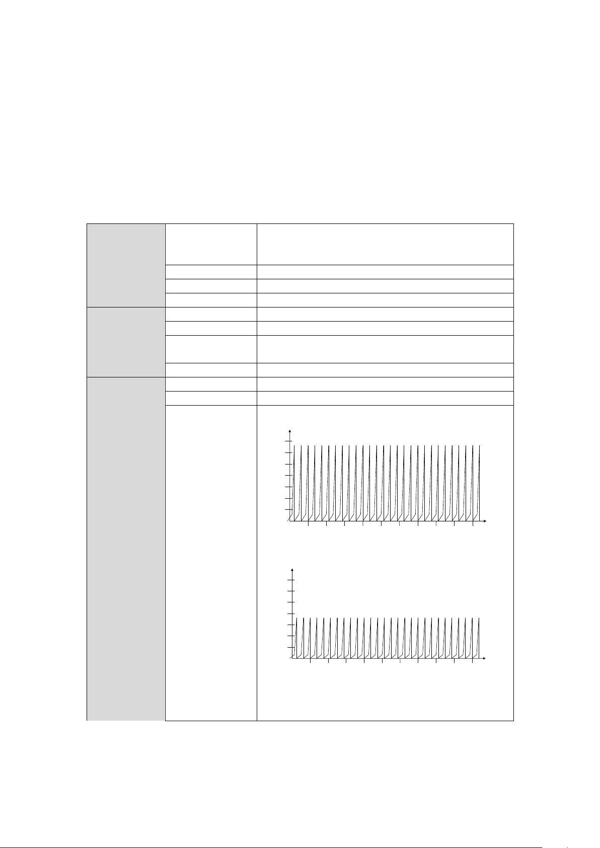
7
Interface X1
Function
GPRS connections to SINAUT MICRO SC
GSM data calls (CSD 9.600 bps) MTC
SMS sending
Standard
RS232 (V.24 / V.28), plug: D-SUB 9 pins
Default speed
9600 bps
Control
AT commands
Air interface
GSM module
GPRS / CSD / Quad band
GPRS
Up to 2 uplinks / up to 4 downlinks (max. 5 Slots)
Transmit power
GSM 850 MHz (max. 2W), GSM 900 MHz (max. 2W),
DCS 1800 MHz (max. 1W), PCS 1900 MHz (max. 1W)
Antenna connector
SMA / 50 Ohm
Power supply
power consumption
typ. 5.5W
Supply voltage
12 - 30 VDC (24 VDC nominal)
Supply current /
Established GPRS
connection with
data exchange
1000
200
400
600
800
1200
1400
[mA]
[ms]
10 20 30 40 50 7060 80 90 100
I
Burst
at 12V
1000
200
400
600
800
1200
1400
[mA]
[ms]
10 20 30 40 50 7060 80 90 100
I
Burst
at 24V
12 V: In = 265 mA, IBurst = 1,3 A
24 V: In = 109 mA, IBurst = 0,8 A
4,62ms Burst repetition rate
Fehler! Verweisquelle konnte nicht gefunden werden. 63
Page 64
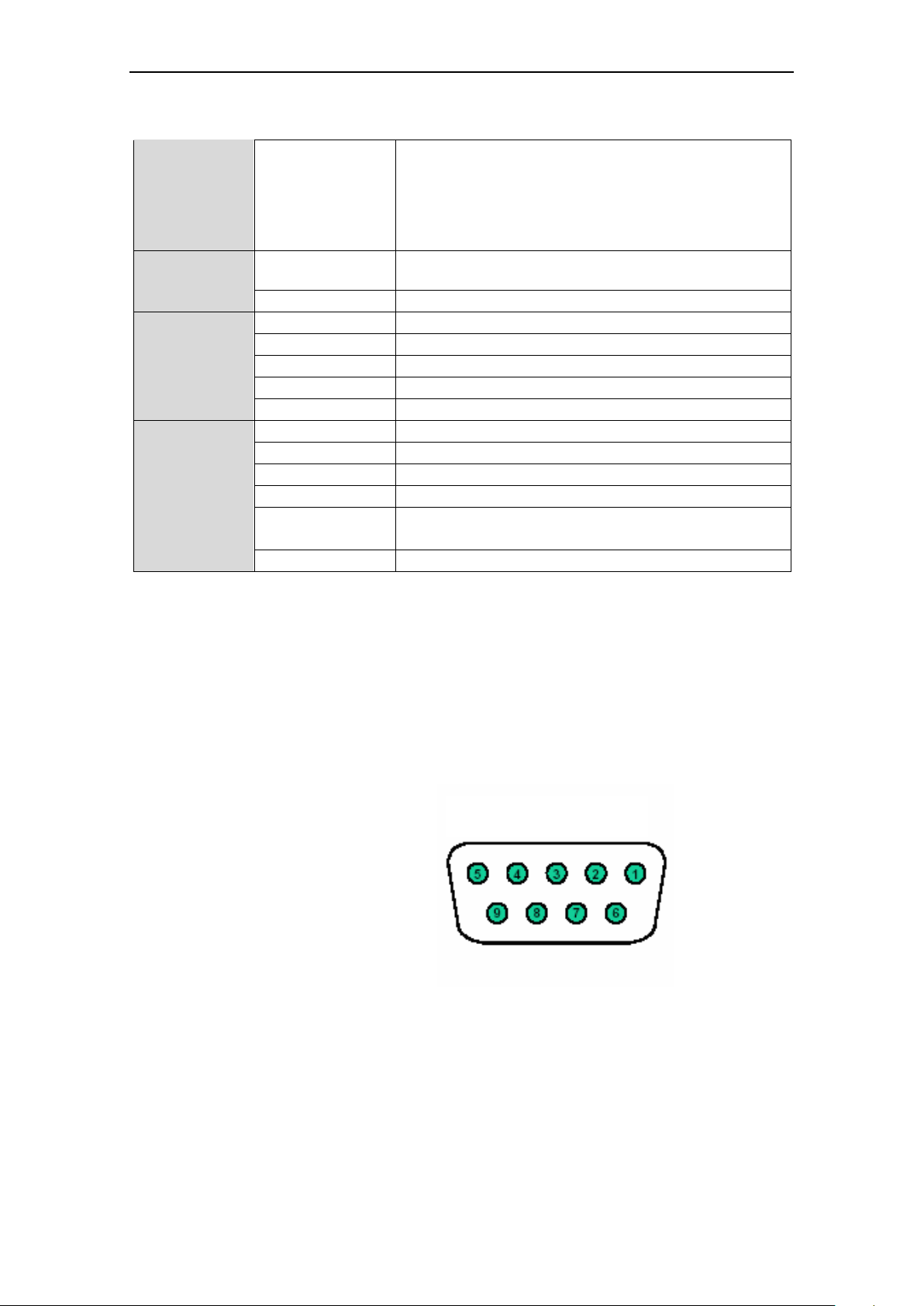
Technical Data
Supply current / no
connection or
connection to
SINAUT MICRO
SC without data
exchange
In 90mA at 12V
In 50mA at 24V
In 40mA at 30V
Ambient
conditions
Temperature range
Operation: –20°C up to +60°C
Storage: –25°C up to +85°C
Humidity
0-95 %, not condensing
Mechanics
Construction
Top-hat rail housing
Material
Synthetic material
Protection category
IP30
Dimensions
30 x 100 x 90 mm
Weight
Approx. 150g
Approvals
CE
Yes
R&TTE
EN 301 511; EN 301 489-1 / -7
EMV / ESD
EN 55024, EN 55022 Class B, EN 61131-2
ATEX
III 3 G EEx nA II T4 Ta=-20°C-60°C
FM
CLI, DIV2, GP. A,B,C,D T4 Ta=-20°C-60°C
CLI, Zone 2 IIC, T4 Ta=-20°C-60°C
UL
E301826
Signals
(Signal direction DTE)
SUB-D9 socket, Pin assignment
RS232
Pin1
DCD
Output
Pin2
RXD
Output
Pin3
TXD
Input
Pin4
DTR
Input
Pin5
GND
Signal ground
Pin6
DSR
Output
Pin7
RTS
Input
Pin8
CTS
Output
Pin9
RI
Output
Interface X1
64 Fehler! Verweisquelle konnte nicht gefunden werden.
Page 65
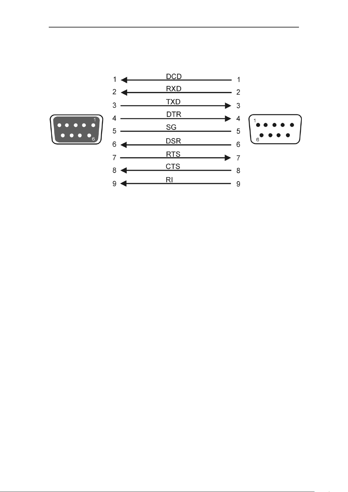
to Modem
DSUB
9-pin
connector
to PC
DSUB
9-pin
plug
Modem cable for Service Interface
Technical Data
The line RI is an option.
Fehler! Verweisquelle konnte nicht gefunden werden. 65
Page 66

Technical Data
66 Fehler! Verweisquelle konnte nicht gefunden werden.
Page 67

Glossary
GSM
Global System for
Mobile
Communication
Global standard for wireless telephony, data and fax transmission and
transmission of text messages (SMS). GSM based networks are
available in a lot of countries world-wide, with high coverage in Europe,
China, Latin America as well as in regions of the USA, Africa and
Russia. Depending on the used frequencies you distinguish PCS
850MHz, GSM 900MHz, DCS 1800MHz und PCS 1900MHz networks.
CSD
Circuit Switched Data
GSM Service for wireless data transmission at 9600 bps full duplex.
Connections can be established to other GSM devices, to analogue
modems or to ISDN modems in wired networks. The connections can
be initialized at both sides. Only dial-up connections are supported.
GPRS
General Packet Radio
Service
GSM service for IP-based data transmission. Over GPRS network
connections are established, either to the internet or to private
networks.. Data are transmitted using the internet protocols TCP/IP or
UDP/IP.
OPC
OPC covers a series of specification for data exchange in automation
technologies between control devices, sensors etc. and control systems
(see www.opcfoundation.org).
Protocol, transmission
protocol
Devices which communicate with one another must use the same rules
for this communication. They must "speak the same language". Such
rules and standards are collectively referred to as a protocol or
transmission protocol. Often used protocols are, for example, TCP/IP
and PPP.
COM-Port
The term "COM port" (communications port) is used to describe a serial
interface (RS232) on a Windows PC. Application programs use COM
ports for data transmission to various devices such as modems, PCs,
terminals etc.
Fehler! Verweisquelle konnte nicht gefunden werden. 67
 Loading...