

Siemens SIMATIC NET IE/AS-INTERFACE LINK PN IO User Manual
Preface, Contents
Technical Description,
Installation Guidelines, Operation
1
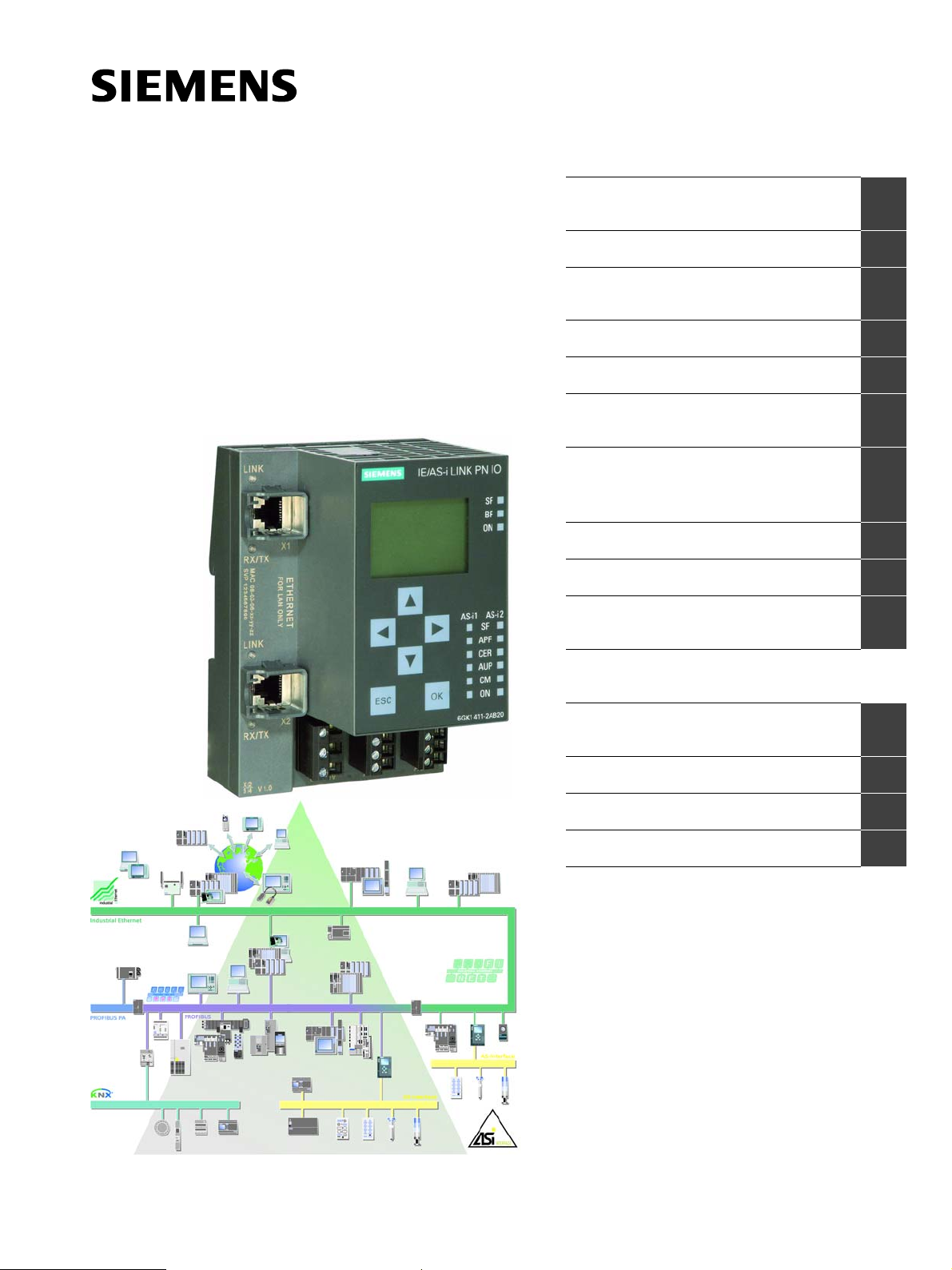
SIMATIC NET
IE/AS−INTERFACE LINK PN IO
as of hardware version 1, as of firmware version V2.0
Manual
Procedure − Configuration
Getting Started − Commissioning
with STEP 7
Keypad and Display
Display / WBM Configuration
Configuring with STEP 7 or a
GSDML File
Data Exchange between
PROFINET IO Controller and
AS−i Slave
Using the Data Record Interface
Diagnostics
Dealing with Problems /
Error Displays
Anhang
2
3
4
5
6
7
8
9
10
Release
C79000−G8976−C216−03
08/2018
AS−Interface Protocol Implemen−
tation Conformance Statement
References
Notes on the CE Label
Glossary
Index
A
B
C
D
Classification of the Safety−Related Notices
This manual contains notices which you should observe to ensure your own personal safety, as well as to protect the product and connected equipment. These notices are highlighted in the manual by a warning triangle and are marked as follows
according to the level of danger:
Danger
!
!
!
indicates that death, severe personal injury will result if proper precautions are not
taken.
Warning
indicates that death, severe personal injury can result if proper precautions are not
taken.
Caution
with warning triangle indicates that minor personal injury can result if proper
precautions are not taken.
Caution
without warning triangle indicates that damage to property can result if proper
precautions are not taken.
Notice
indicates that an undesirable result or status can occur if the relevant notice is
ignored.
Note
highlights important information on the product, using the product, or part of the
documentation that is of particular importance and that will be of benefit to the
user.
2
IE/AS−INTERFACE LINK PN IO as of hardware version 1, as of firmware version V2.0
C79000−G8976−C216−03
Release 08/2018
Trademarks
SIMATICR, SIMATIC HMIR and SIMATIC NETR are registered trademarks of
SIEMENS AG.
Third parties using for their own purposes any other names in this document which
refer to trademarks might infringe upon the rights of the trademark owners.
Safety Instructions Regarding your Product
Before you use the product described here, read the safety instructions below thoroughly.
Qualified Personnel
Only qualified personnel should be allowed to install and work on this equipment.
Qualified persons are defined as persons who are authorized to commission, to
ground, and to tag circuits, equipment, and systems in accordance with established safety practices and standards.
Correct Usage of Hardware Products
Note the following:
Warning
!
This device and its components may only be used for the applications described in
the catalog or the technical description, and only in connection with devices or
components from other manufacturers which have been approved or
recommended by Siemens.
This product can only function correctly and safely if it is transported, stored, set
up, and installed correctly, and operated and maintained as recommended.
Before you use the supplied sample programs or programs you have written
yourself, make certain that no injury to persons nor damage to equipment can
result in your plant or process.
EC Notice: Commissioning must not be carried out until it has been established
that the machine in which this component is to be installed complies with the
conditions of directive 98/37/EC.
Correct Usage of Software Products
Note the following:
Warning
!
This software may only be used for the applications described in the catalog or the
technical description, and only in connection with devices or software products
from other manufacturers which have been approved or recommended by
Siemens.
Before you use the supplied sample programs or programs you have written
yourself, make certain that no injury to persons nor damage to equipment can
result in your plant or process.
IE/AS−INTERFACE LINK PN IO as of hardware version 1, as of firmware version V2.0
Release 08/2018
C79000−G8976−C216−03
3

Prior to Startup
Before putting the product into operation, note the following:
Caution
Prior to startup you must observe the instructions in the relevant documentation.
For ordering data of the documentation please refer to the catalogs or contact your
local SIEMENS representative.
DisclaimerCopyright E Siemens AG 2006 − 2008 All rights reserved
The reproduction, transmission or use of this document or its contents is not
permitted without express written authority. Offenders will be liable for
damages. All rights, including rights created by patent grant or registration of
a utility model or design, are reserved.
4
Siemens AG
Industry Automation
Industrial Communication
Postfach 4848, D-90327 Nürnberg
Siemens Aktiengesellschaft G79000−G8900−C216−03
IE/AS−INTERFACE LINK PN IO as of hardware version 1, as of firmware version V2.0
We have checked the contents of this manual for agreement with the hardware and software described. Since deviations cannot be precluded entirely,
we cannot guarantee full agreement. However, the data in this manual are
reviewed regularly and any necessary corrections included in subsequent
editions. Suggestions for improvement are welcomed.
Technical data subject to change.
Release 03/2008
C79000−G8976−C216−03

Preface
Purpose of the Manual
This manual supports you when using the IE/AS-INTERFACE LINK PN IO
module. The product name is also shortened to IE/AS-i LINK in the manual. It
contains information about how PROFINET IO controllers can address AS-i
actuators and AS-i sensors via this module.
Validity of the Manual
This manual is valid for the IE/AS-INTERFACE LINK PN IO module as of hardware
version 1 and as of firmware version V2.0 and the STEP 7 configuration software
as of V5.4 SP3 / NCM PC as of V5.4 SP3.
What’s new?
This issue of the manual includes several corrections.
We recommend the following procedure
... If you want an overall picture of the AS-Interface:
... If you want to set up an AS-i system and include the IE/AS-i LINK in it:
... If you want to know how to operate the IE/AS-i LINK from the point of view of
Requirements
To understand this manual, you require the following:
S A working knowledge of PROFINET IO
S Knowledge of the manual ’AS-Interface Introduction and Basic Information’
− First read the ‘AS-Interface Introduction and Basic Information’ manual (not
part of this documentation package). This contains general information
about the AS-Interface, abbreviated to AS-i in the following chapters.
− You will find the information you require about connecting and operating the
IE/AS-i LINK in Chapter 1 and 3.
the PROFINET IO
controller:
− Read Chapters 5 − 6 in this manual.
− Chapter 8 explains the data record interface.
IE/AS−INTERFACE LINK PN IO as of hardware version 1, as of firmware version V2.0
Release 08/2018
C79000−G8976−C216−03
5

Preface
GSDML file
The GSDML file that you optionally require for configuring the IE/AS−i LINK
(see Chapter 6) can be downloaded from the Internet at the following link:
http://support.automation.siemens.com/WW/view/en/23742537
Symbols used in the manual
You will find this symbol in Chapter 5 where it is used to identify the description of
menu sequences on the display and keyboard.
FAQs
You will find FAQs on Siemens AS−i products on the Internet on the Service and
Support pages of Industry Automation at the following address:
http://support.automation.siemens.com/WW/view/en/10805888
-
6
IE/AS−INTERFACE LINK PN IO as of hardware version 1, as of firmware version V2.0
C79000−G8976−C216−03
Release 08/2018

Contents
Preface 5. . . . . . . . . . . . . . . . . . . . . . . . . . . . . . . . . . . . . . . . . . . . . . . . . . . . . . . . . . . . . . . .
Contents 7. . . . . . . . . . . . . . . . . . . . . . . . . . . . . . . . . . . . . . . . . . . . . . . . . . . . . . . . . . . . . . .
1 Technical Description, Installation Guidelines, Operation 11. . . . . . . . . . . . . . . . .
1.1 General Notes on Operation − Safety Warnings 11. . . . . . . . . . . . . . . . . .
1.2 Uses of the Module 13. . . . . . . . . . . . . . . . . . . . . . . . . . . . . . . . . . . . . . . . . . .
1.3 Technical Specifications of the Module 15. . . . . . . . . . . . . . . . . . . . . . . . . .
1.4 Approvals 16. . . . . . . . . . . . . . . . . . . . . . . . . . . . . . . . . . . . . . . . . . . . . . . . . . .
1.5 Installation Guidelines and Installing the Module 17. . . . . . . . . . . . . . . . . .
1.6 Front Panel − Access to all Functions 19. . . . . . . . . . . . . . . . . . . . . . . . . . .
1.7 Connection Elements 20. . . . . . . . . . . . . . . . . . . . . . . . . . . . . . . . . . . . . . . . .
1.7.1 Connectors for the AS-i Cable(s) and Power Supply 21. . . . . . . . . . . . . . .
1.8 C-PLUG (Configuration Plug) 24. . . . . . . . . . . . . . . . . . . . . . . . . . . . . . . . . .
1.9 Display and Control Elements 26. . . . . . . . . . . . . . . . . . . . . . . . . . . . . . . . . .
1.10 Settings when Using a Firewall 29. . . . . . . . . . . . . . . . . . . . . . . . . . . . . . . . .
2 Procedure − Configuration 30. . . . . . . . . . . . . . . . . . . . . . . . . . . . . . . . . . . . . . . . . . . . . .
2.1 What to do − an Overview 30. . . . . . . . . . . . . . . . . . . . . . . . . . . . . . . . . . . . .
2.2 Configuration Options 31. . . . . . . . . . . . . . . . . . . . . . . . . . . . . . . . . . . . . . . . .
3 Getting Started − Commissioning with STEP 7 32. . . . . . . . . . . . . . . . . . . . . . . . . . .
3.1 Commissioning the IE/AS-INTERFACE LINK PN IO 32. . . . . . . . . . . . . .
3.1.1 Requirements 32. . . . . . . . . . . . . . . . . . . . . . . . . . . . . . . . . . . . . . . . . . . . . . . .
3.1.2 Procedure 33. . . . . . . . . . . . . . . . . . . . . . . . . . . . . . . . . . . . . . . . . . . . . . . . . . .
4 Keypad and Display 36. . . . . . . . . . . . . . . . . . . . . . . . . . . . . . . . . . . . . . . . . . . . . . . . . . . .
4.1 Configuration and Modes 37. . . . . . . . . . . . . . . . . . . . . . . . . . . . . . . . . . . . . .
4.2 Buttons and Working in the Menus 38. . . . . . . . . . . . . . . . . . . . . . . . . . . . . .
4.3 Working Examples 40. . . . . . . . . . . . . . . . . . . . . . . . . . . . . . . . . . . . . . . . . . .
4.3.1 Example: Changing the status
“Protected mode” <−> “Configuration mode” 40. . . . . . . . . . . . . . . . . . . .
4.3.2 Example: Changing the PROFINET device name 41. . . . . . . . . . . . . . . . .
4.4 Menu Structure 41. . . . . . . . . . . . . . . . . . . . . . . . . . . . . . . . . . . . . . . . . . . . . .
5 Display / WBM Configuration 46. . . . . . . . . . . . . . . . . . . . . . . . . . . . . . . . . . . . . . . . . . .
5.1 Web Based Management (WBM) with the IE/AS-i LINK 47. . . . . . . . . . . .
5.1.1 WBM − Requirements and Starting Up 47. . . . . . . . . . . . . . . . . . . . . . . . . .
5.1.2 Working with WBM 50. . . . . . . . . . . . . . . . . . . . . . . . . . . . . . . . . . . . . . . . . . .
5.2 Configuration and Diagnostics 51. . . . . . . . . . . . . . . . . . . . . . . . . . . . . . . . . .
IE/AS−INTERFACE LINK PN IO as of hardware version 1, as of firmware version V2.0
Release 08/2018
C79000−G8976−C216−03
7

Contents
5.2.1 Navigation “System −> System Configuration” 51. . . . . . . . . . . . . . . . . . . .
5.2.1.1 General 51. . . . . . . . . . . . . . . . . . . . . . . . . . . . . . . . . . . . . . . . . . . . . . . . . . . . . . . .
5.2.1.2 Identification & Maintenance 53. . . . . . . . . . . . . . . . . . . . . . . . . . . . . . . . . . . . . .
5.2.1.3 Settings 54. . . . . . . . . . . . . . . . . . . . . . . . . . . . . . . . . . . . . . . . . . . . . . . . . . . . . . . .
5.2.2 Navigation “System −> Reset” 55. . . . . . . . . . . . . . . . . . . . . . . . . . . . . . . . .
5.2.3 Navigation “System −> Save & Download” 56. . . . . . . . . . . . . . . . . . . . . . .
5.2.3.1 HTTP (Hypertext Transfer Protocol) 56. . . . . . . . . . . . . . . . . . . . . . . . . . . . . . . .
5.2.3.2 TFTP (Trivial File Transfer Protocol) 57. . . . . . . . . . . . . . . . . . . . . . . . . . . . . . .
5.2.4 Navigation “System −> Password” 58. . . . . . . . . . . . . . . . . . . . . . . . . . . . . .
5.2.5 Navigation “System −> Device Display” 59. . . . . . . . . . . . . . . . . . . . . . . . . .
5.2.6 Navigation “System −> Diagnostic >Buffer” 60. . . . . . . . . . . . . . . . . . . . . .
5.2.6.1 Diagnostic Buffer 60. . . . . . . . . . . . . . . . . . . . . . . . . . . . . . . . . . . . . . . . . . . . . . . .
5.2.6.2 Events 61. . . . . . . . . . . . . . . . . . . . . . . . . . . . . . . . . . . . . . . . . . . . . . . . . . . . . . . . .
5.2.7 Navigation “System −> C-PLUG” 62. . . . . . . . . . . . . . . . . . . . . . . . . . . . . . .
5.2.8 Navigation “System −> Internet” 64. . . . . . . . . . . . . . . . . . . . . . . . . . . . . . . .
5.2.9 Navigation “Industrial Ethernet −> Configuration” 65. . . . . . . . . . . . . . . . .
5.2.9.1 IP Configuration 66. . . . . . . . . . . . . . . . . . . . . . . . . . . . . . . . . . . . . . . . . . . . . . . . .
5.2.9.2 Events 68. . . . . . . . . . . . . . . . . . . . . . . . . . . . . . . . . . . . . . . . . . . . . . . . . . . . . . . . .
5.2.9.3 E-mail 69. . . . . . . . . . . . . . . . . . . . . . . . . . . . . . . . . . . . . . . . . . . . . . . . . . . . . . . . .
5.2.9.4 SNMP 70. . . . . . . . . . . . . . . . . . . . . . . . . . . . . . . . . . . . . . . . . . . . . . . . . . . . . . . . .
5.2.9.5 Time Synchronization 71. . . . . . . . . . . . . . . . . . . . . . . . . . . . . . . . . . . . . . . . . . . .
5.2.10 Navigation “Industrial Ethernet −> Ports” 73. . . . . . . . . . . . . . . . . . . . . . . .
5.2.10.1 Ports 73. . . . . . . . . . . . . . . . . . . . . . . . . . . . . . . . . . . . . . . . . . . . . . . . . . . . . . . . . .
5.2.10.2 FDB (forwarding database) 74. . . . . . . . . . . . . . . . . . . . . . . . . . . . . . . . . . . . . . .
5.2.10.3 ARP (Address Resolution Protocol) 74. . . . . . . . . . . . . . . . . . . . . . . . . . . . . . . .
5.2.11 Navigation “Industrial Ethernet −> Statistics” 75. . . . . . . . . . . . . . . . . . . . .
5.2.11.1 Throughput 75. . . . . . . . . . . . . . . . . . . . . . . . . . . . . . . . . . . . . . . . . . . . . . . . . . . . .
5.2.11.2 Packet Type 76. . . . . . . . . . . . . . . . . . . . . . . . . . . . . . . . . . . . . . . . . . . . . . . . . . . .
5.2.11.3 Packet Size 76. . . . . . . . . . . . . . . . . . . . . . . . . . . . . . . . . . . . . . . . . . . . . . . . . . . .
5.2.11.4 Error 77. . . . . . . . . . . . . . . . . . . . . . . . . . . . . . . . . . . . . . . . . . . . . . . . . . . . . . . . . . .
5.2.12 Navigation “PROFINET IO −> Status” 78. . . . . . . . . . . . . . . . . . . . . . . . . . .
5.2.12.1 Status 78. . . . . . . . . . . . . . . . . . . . . . . . . . . . . . . . . . . . . . . . . . . . . . . . . . . . . . . . .
5.2.13 Navigation “AS-i Line 1 −> Overview” 79. . . . . . . . . . . . . . . . . . . . . . . . . . .
5.2.13.1 Lifelist 79. . . . . . . . . . . . . . . . . . . . . . . . . . . . . . . . . . . . . . . . . . . . . . . . . . . . . . . . .
5.2.13.2 Error Statistics 80. . . . . . . . . . . . . . . . . . . . . . . . . . . . . . . . . . . . . . . . . . . . . . . . . .
5.2.14 Navigation “AS-i Line 1 −> Configuration” 83. . . . . . . . . . . . . . . . . . . . . . . .
5.2.14.1 Status 83. . . . . . . . . . . . . . . . . . . . . . . . . . . . . . . . . . . . . . . . . . . . . . . . . . . . . . . . .
5.2.14.2 Total Configuration 84. . . . . . . . . . . . . . . . . . . . . . . . . . . . . . . . . . . . . . . . . . . . . .
5.2.15 Navigation “AS-i Line 1 −> Slaves” 87. . . . . . . . . . . . . . . . . . . . . . . . . . . . . .
5.2.15.1 Diagnostics 87. . . . . . . . . . . . . . . . . . . . . . . . . . . . . . . . . . . . . . . . . . . . . . . . . . . . .
5.2.15.2 Configuration 89. . . . . . . . . . . . . . . . . . . . . . . . . . . . . . . . . . . . . . . . . . . . . . . . . . .
5.2.15.3 Cyclic Data 90. . . . . . . . . . . . . . . . . . . . . . . . . . . . . . . . . . . . . . . . . . . . . . . . . . . . .
5.2.15.4 Current Parameters 91. . . . . . . . . . . . . . . . . . . . . . . . . . . . . . . . . . . . . . . . . . . . .
5.2.15.5 String Transfer 92. . . . . . . . . . . . . . . . . . . . . . . . . . . . . . . . . . . . . . . . . . . . . . . . . .
5.2.16 Navigation “AS-i line 1 −> Change Address” 94. . . . . . . . . . . . . . . . . . . . .
5.2.16.1 Change Address 94. . . . . . . . . . . . . . . . . . . . . . . . . . . . . . . . . . . . . . . . . . . . . . . .
5.2.16.2 Change ID1 94. . . . . . . . . . . . . . . . . . . . . . . . . . . . . . . . . . . . . . . . . . . . . . . . . . . .
8
IE/AS−INTERFACE LINK PN IO as of hardware version 1, as of firmware version V2.0
C79000−G8976−C216−03
Release 08/2018

5.2.16.3 Automatic Addressing 95. . . . . . . . . . . . . . . . . . . . . . . . . . . . . . . . . . . . . . . . . . . .
6 Configuring with STEP 7 or a GSDML File 96. . . . . . . . . . . . . . . . . . . . . . . . . . . . . . .
6.1 General Information on Configuration 97. . . . . . . . . . . . . . . . . . . . . . . . . . .
6.1.1 Basics 97. . . . . . . . . . . . . . . . . . . . . . . . . . . . . . . . . . . . . . . . . . . . . . . . . . . . . .
6.1.2 Choosing the Configuration Method 98. . . . . . . . . . . . . . . . . . . . . . . . . . . . .
6.2 Configuring with STEP 7 99. . . . . . . . . . . . . . . . . . . . . . . . . . . . . . . . . . . . . .
6.2.1 Configuring the IE/AS-i LINK 99. . . . . . . . . . . . . . . . . . . . . . . . . . . . . . . . . . .
6.2.2 Configuring and Assigning Parameters to the AS-i Slaves 103. . . . . . . . . .
6.3 Configuration with the GSDML File 107. . . . . . . . . . . . . . . . . . . . . . . . . . . . .
6.3.1 Installing the GSDML File 107. . . . . . . . . . . . . . . . . . . . . . . . . . . . . . . . . . . . .
6.3.2 Configuring the IE/AS-i LINK 107. . . . . . . . . . . . . . . . . . . . . . . . . . . . . . . . . . .
6.3.3 Configuring and Assigning Parameters to the AS-i Slaves 109. . . . . . . . . .
7 Data Exchange between PROFINET IO Controller and AS-i Slave 111. . . . . . . . . .
7.1 How the interfaces work 112. . . . . . . . . . . . . . . . . . . . . . . . . . . . . . . . . . . . . . .
7.2 Transferring AS-i Digital Values 113. . . . . . . . . . . . . . . . . . . . . . . . . . . . . . . .
7.2.1 Addressing AS-i Slaves 113. . . . . . . . . . . . . . . . . . . . . . . . . . . . . . . . . . . . . . .
7.2.2 Special Feature of AS-i Analog Slaves 114. . . . . . . . . . . . . . . . . . . . . . . . . .
7.2.3 Special Features of AS-i Safety Slaves 114. . . . . . . . . . . . . . . . . . . . . . . . . .
Contents
7.3 Transferring AS-i Analog Values 115. . . . . . . . . . . . . . . . . . . . . . . . . . . . . . . .
7.3.1 Accessing AS-i Analog Data using Acyclic Services 116. . . . . . . . . . . . . . .
7.3.2 Special Situations in Analog Value Transfer 117. . . . . . . . . . . . . . . . . . . . . .
8 Using the Data Record Interface 118. . . . . . . . . . . . . . . . . . . . . . . . . . . . . . . . . . . . . . . . .
8.1 Data Record Interface of the IE/AS-i LINK 118. . . . . . . . . . . . . . . . . . . . . . .
8.2 Description of the AS-i Line and AS-i Slave Calls 122. . . . . . . . . . . . . . . . .
8.2.1 AS-i Line Calls 125. . . . . . . . . . . . . . . . . . . . . . . . . . . . . . . . . . . . . . . . . . . . . . .
8.2.1.1 Store_Actual_Parameters 125. . . . . . . . . . . . . . . . . . . . . . . . . . . . . . . . . . . . . . . .
8.2.1.2 Store_Actual_Configuration 126. . . . . . . . . . . . . . . . . . . . . . . . . . . . . . . . . . . . . . .
8.2.1.3 Set_LPS 127. . . . . . . . . . . . . . . . . . . . . . . . . . . . . . . . . . . . . . . . . . . . . . . . . . . . . . .
8.2.1.4 Get_LPS_LAS_LDS_LPF_Flags 128. . . . . . . . . . . . . . . . . . . . . . . . . . . . . . . . . .
8.2.1.5 Get_LAS_CDI_PI_Flags 132. . . . . . . . . . . . . . . . . . . . . . . . . . . . . . . . . . . . . . . . .
8.2.1.6 Set_LPS_PCD_PP_Flags 135. . . . . . . . . . . . . . . . . . . . . . . . . . . . . . . . . . . . . . . .
8.2.1.7 Set_Operation_Mode 138. . . . . . . . . . . . . . . . . . . . . . . . . . . . . . . . . . . . . . . . . . . .
8.2.1.8 Set_Offline_Mode 139. . . . . . . . . . . . . . . . . . . . . . . . . . . . . . . . . . . . . . . . . . . . . . .
8.2.1.9 Change_Slave_Address 140. . . . . . . . . . . . . . . . . . . . . . . . . . . . . . . . . . . . . . . . . .
8.2.1.10 Set_Auto_Addr_Enable 141. . . . . . . . . . . . . . . . . . . . . . . . . . . . . . . . . . . . . . . . . .
8.2.1.11 Write_Extended_ID−Code_1 142. . . . . . . . . . . . . . . . . . . . . . . . . . . . . . . . . . . . . .
8.2.1.12 Read_AIDI 143. . . . . . . . . . . . . . . . . . . . . . . . . . . . . . . . . . . . . . . . . . . . . . . . . . . . .
8.2.1.13 Write_AODI 145. . . . . . . . . . . . . . . . . . . . . . . . . . . . . . . . . . . . . . . . . . . . . . . . . . . .
8.2.1.14 Read_AS-i_Line_Errorcounters 146. . . . . . . . . . . . . . . . . . . . . . . . . . . . . . . . . . .
8.2.1.15 Read_and_Delete_AS-i_Line_Errorcounters 148. . . . . . . . . . . . . . . . . . . . . . . .
8.2.2 AS-i Slave Calls 150. . . . . . . . . . . . . . . . . . . . . . . . . . . . . . . . . . . . . . . . . . . . . .
8.2.2.1 Set_Permanent_Parameter 150. . . . . . . . . . . . . . . . . . . . . . . . . . . . . . . . . . . . . . .
IE/AS−INTERFACE LINK PN IO as of hardware version 1, as of firmware version V2.0
Release 08/2018
C79000−G8976−C216−03
9

Contents
8.2.2.2 Get_Permanent_Parameter 151. . . . . . . . . . . . . . . . . . . . . . . . . . . . . . . . . . . . . . .
8.2.2.3 Write_Parameter 152. . . . . . . . . . . . . . . . . . . . . . . . . . . . . . . . . . . . . . . . . . . . . . . .
8.2.2.4 Read_Parameter 153. . . . . . . . . . . . . . . . . . . . . . . . . . . . . . . . . . . . . . . . . . . . . . . .
8.2.2.5 Set_Permanent_Configuration 154. . . . . . . . . . . . . . . . . . . . . . . . . . . . . . . . . . . .
8.2.2.6 Get_Permanent_Configuration 155. . . . . . . . . . . . . . . . . . . . . . . . . . . . . . . . . . . .
8.2.2.7 Read_Actual_Configuration 156. . . . . . . . . . . . . . . . . . . . . . . . . . . . . . . . . . . . . . .
8.2.2.8 Read_Parameter_String 157. . . . . . . . . . . . . . . . . . . . . . . . . . . . . . . . . . . . . . . . . .
8.2.2.9 Write_Parameter_String 158. . . . . . . . . . . . . . . . . . . . . . . . . . . . . . . . . . . . . . . . . .
8.2.2.10 Read_Diagnostic_String 159. . . . . . . . . . . . . . . . . . . . . . . . . . . . . . . . . . . . . . . . . .
8.2.2.11 Read_Identification_String 160. . . . . . . . . . . . . . . . . . . . . . . . . . . . . . . . . . . . . . . .
8.2.2.12 Write_CTT2_String 161. . . . . . . . . . . . . . . . . . . . . . . . . . . . . . . . . . . . . . . . . . . . . .
8.2.2.13 Read_CTT2_String 162. . . . . . . . . . . . . . . . . . . . . . . . . . . . . . . . . . . . . . . . . . . . . .
8.2.2.14 Read_I/O_Configuration 163. . . . . . . . . . . . . . . . . . . . . . . . . . . . . . . . . . . . . . . . . .
8.2.2.15 Read_ID−Code 164. . . . . . . . . . . . . . . . . . . . . . . . . . . . . . . . . . . . . . . . . . . . . . . . .
8.2.2.16 Read_Extended_ID−Code_1 165. . . . . . . . . . . . . . . . . . . . . . . . . . . . . . . . . . . . . .
8.2.2.17 Read_Extended_ID−Code_2 166. . . . . . . . . . . . . . . . . . . . . . . . . . . . . . . . . . . . . .
8.2.2.18 Read_Status 167. . . . . . . . . . . . . . . . . . . . . . . . . . . . . . . . . . . . . . . . . . . . . . . . . . .
8.2.2.19 Get_Write_Parameter_Echo 168. . . . . . . . . . . . . . . . . . . . . . . . . . . . . . . . . . . . . .
8.2.2.20 Write_Analog_Output_Data 169. . . . . . . . . . . . . . . . . . . . . . . . . . . . . . . . . . . . . . .
8.2.2.21 Read_Analog_Input_Data 170. . . . . . . . . . . . . . . . . . . . . . . . . . . . . . . . . . . . . . . .
8.2.2.22 Read_AS-i_Slave_Errorcounters 171. . . . . . . . . . . . . . . . . . . . . . . . . . . . . . . . . .
8.2.2.23 Read_and_Delete_AS-i_Slave_Errorcounters 172. . . . . . . . . . . . . . . . . . . . . . .
9 Diagnostics 173. . . . . . . . . . . . . . . . . . . . . . . . . . . . . . . . . . . . . . . . . . . . . . . . . . . . . . . . . . . .
9.1 Overview 173. . . . . . . . . . . . . . . . . . . . . . . . . . . . . . . . . . . . . . . . . . . . . . . . . . . .
9.2 Interrupts 173. . . . . . . . . . . . . . . . . . . . . . . . . . . . . . . . . . . . . . . . . . . . . . . . . . . .
9.2.1 Remove/Insert Module Interrupts 173. . . . . . . . . . . . . . . . . . . . . . . . . . . . . . .
9.2.2 Diagnostic Interrupts 174. . . . . . . . . . . . . . . . . . . . . . . . . . . . . . . . . . . . . . . . . .
9.3 Diagnose Data Records 175. . . . . . . . . . . . . . . . . . . . . . . . . . . . . . . . . . . . . . .
10 Dealing with Problems / Error Displays 176. . . . . . . . . . . . . . . . . . . . . . . . . . . . . . . . .
10.1 Replacing a Defective AS-i Slave/Automatic Address Programming 176.
10.2 Error Displays/Remedying Errors 177. . . . . . . . . . . . . . . . . . . . . . . . . . . . . . .
A AS-Interface Protocol Implementation Conformance Statement (PICS) 180. . . . .
B References 184. . . . . . . . . . . . . . . . . . . . . . . . . . . . . . . . . . . . . . . . . . . . . . . . . . . . . . . . . . . .
C Notes on the CE Mark 185. . . . . . . . . . . . . . . . . . . . . . . . . . . . . . . . . . . . . . . . . . . . . . . . . .
D Glossary 186. . . . . . . . . . . . . . . . . . . . . . . . . . . . . . . . . . . . . . . . . . . . . . . . . . . . . . . . . . . . . .
D.1 Terms Relating to AS-Interface 186. . . . . . . . . . . . . . . . . . . . . . . . . . . . . . . . .
D.2 Terms Relating to PROFINET 189. . . . . . . . . . . . . . . . . . . . . . . . . . . . . . . . . .
Index 190. . . . . . . . . . . . . . . . . . . . . . . . . . . . . . . . . . . . . . . . . . . . . . . . . . . . . . . . . . . . . . . . . .
10
IE/AS−INTERFACE LINK PN IO as of hardware version 1, as of firmware version V2.0
C79000−G8976−C216−03
Release 08/2018

1 Technical Description, Installation Guidelines,
Operation
This chapter...
This chapter will familiarize you with the performance characteristics, basic
functions and installation of the IE/AS-INTERFACE LINK PN IO master module.
You will learn the following:
S How to install the IE/AS-i LINK
S Which display and control elements the IE/AS-i LINK provides.
1.1 General Notes on Operation − Safety Warnings
Warning
!
WARNING − EXPLOSION HAZARD: DO NOT DISCONNECT EQUIPMENT
WHEN A FLAMMABLE OR COMBUSTIBLE ATMOSPHERE IS PRESENT.
Warning
!
!
When used under hazardous conditions (zone 2), devices of the
IE/AS-INTERFACE LINK PN IO product line must be installed in an enclosure.
To comply with ATEX95 (previously ATEX100a) EN 60079-15, this enclosure must
meet the requirements of at least IP54 in compliance with EN 60529.
Warning
When used under hazardous conditions:
S If the temperature of the cable or wiring entry point exceeds 70°C or the
temperature of the connecting terminal on the IE/AS-i LINK exceeds 80 °C,
special precautions must be taken:
If the IE/AS-i LINK is operated at ambient temperatures 50°C to 60°C, only
cables with a maximum permitted temperature of at least 80°C may be used.
S Provisions shall be made to prevent the rated voltage from being exceeded by
transient disturbances of more than 40%.
This criterion is fulfilled, if supplies are derived from SELV (Safety Extra Low
Voltage), only.
S The IE/AS-i LINK is intended only for vertical installation.
IE/AS−INTERFACE LINK PN IO as of hardware version 1, as of firmware version V2.0
Release 08/2018
C79000−G8976−C216−03
11
1 Technical Description, Installation Guidelines, Operation
Warning
!
S ”WARNING” − Explosion Hazard − Do not disconnect while circuit is live unless
area is known to be non-hazardous.
S ”WARNING” − Explosion Hazard − Substitution of components may impair
suitability for Class I, Division 2 or Zone 2.
S This equipment is suitable for use in Class I, Division 2, Groups A, B, C, D;
Class I, Zone 2, Group IIC or non-hazardous locations.
Caution
!
When handling and installing the IE/AS-INTERFACE LINK PN IO, make sure that
you adhere to the ESD guidelines.
Note
The IE/AS-i LINK can be configured, installed and started up independent of the
PROFINET installation.
12
IE/AS−INTERFACE LINK PN IO as of hardware version 1, as of firmware version V2.0
C79000−G8976−C216−03
Release 08/2018
1 Technical Description, Installation Guidelines, Operation
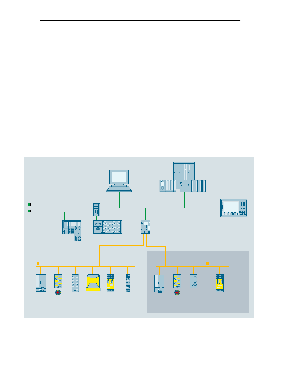
1.2 Uses of the Module
PROFINET IO Device and AS-Interface Master
The IE/AS-i LINK is both a PROFINET IO device and AS-Interface master:
S IE/AS-i LINK connects the actuator-sensor interface with PROFINET IO.
S Using the IE/AS-i LINK module, you can access the inputs and outputs of the
AS-i slaves from PROFINET IO Depending on the slave type, you can access
binary values and / or analog values.
The following AS-i slaves can be used:
− Standard slaves / analog slaves / combi slaves
− Slaves with the extended addressing mode
− Slaves with data transfer mechanisms complying with the AS-i specification
V3.0 − Combined Transaction Type (CTT) 1−5.
PROFINET
Industrial Ethernet
AS-Interface
Power
supply
Safe
slave with
EMERGENCYSTOP
ET 200SP
Slave
Laser
scanner
SCALANCE
XC208
ET 200pro
MSS
ASIsafe
SIMATIC
Software Controller
3RA2 load
feeders
SIMATIC/
SIMOTION
IE/AS-i Link PN IO
When IE/AS-i Link PN IO is used
as double master
Power
supply
Safe
slave with
EMERGENCYSTOP
Slave
SIMATIC HMI
AS-Interface
MSS
ASIsafe
IK10_40017c
Figure 1-1 Example of a System Configuration with the IE/AS-INTERFACE LINK PN IO (double
master)
IE/AS−INTERFACE LINK PN IO as of hardware version 1, as of firmware version V2.0
Release 08/2018
C79000−G8976−C216−03
13

1 Technical Description, Installation Guidelines, Operation
Features
The IE/AS-INTERFACE LINK PN IO is a PROFINET device (complying with IEC
61158) and AS-Interface master (complying with the AS-Interface specification
V3.0 according to EN 50 295) and allows transparent data access to the
AS-Interface from PROFINET IO.
PROFINET IO controllers can exchange IO data cyclically with the lower-level
AS-Interface slaves. Acyclic services can also be used for AS-i calls (parameters,
diagnostics).
Apart from the digital I/O data, analog data is also stored quickly in the cyclic I/O
area of an SIMATIC S7 CPU (no separate communication block call necessary).
The IE/AS-i LINK is available as a single or double master
(applications with large numbers of slaves −> doubles the configuration limits).
The complete underlying AS-i line can be configured on an integrated operator
display in the IE/AS-i LINK (for example addressing the AS-i slaves, I/O test of all
digital and analog slaves).
During operation, you have detailed diagnostic information available on the display
allowing a fault to be localized immediately, when necessary.
The essential features are as follows:
S Single and double AS-Interface master (complying with AS-Interface
specification V3.0) for the connection of 62 AS-Interface slaves per master and
integrated analog value transfer
S Support of the real-time function (RT) of PROFINET IO
S Integrated ground fault monitoring for the AS-Interface cable
S Convenient diagnostics and commissioning on site using full graphics display or
over Web interface with standard browser
S Configuration with STEP 7 or integration using the PROFINET type file
(GSDML file)
S Vertical integration (standard Web interface) over Industrial Ethernet
S Power supply from the AS-Interface cable (line 1), therefore no extra power
supply necessary. As an alternative, a 24 V DC power supply can be used.
S Module replacement without PG by using C-PLUG
Components of the Product
14
The IE/AS-i LINK product includes the following components:
S IE/AS-INTERFACE LINK PN IO
S Product information for the IE/AS-INTERFACE LINK PN IO
IE/AS−INTERFACE LINK PN IO as of hardware version 1, as of firmware version V2.0
C79000−G8976−C216−03
Release 08/2018

1 Technical Description, Installation Guidelines, Operation
1.3 Technical Specifications of the Module
The IE/AS-INTERFACE LINK module has the following technical data:
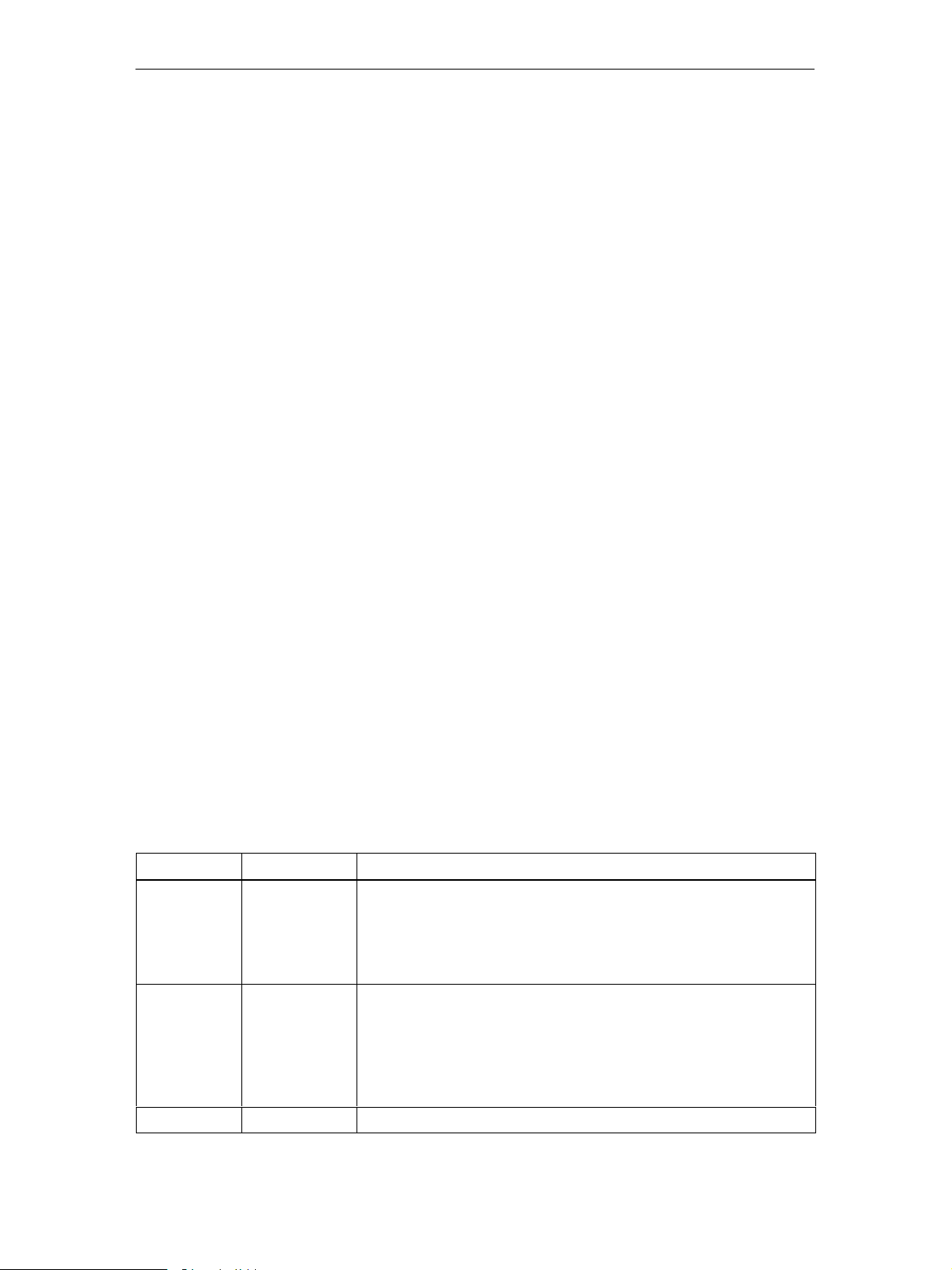
Table 1-1 Technical Specifications
Feature Explanation/Values
AS-i cycle time
(The values apply for the possible full configuration
of an AS-i network on the IE/AS-INTERFACE LINK
in each case)
Configuration of the AS-Interface S via keyboard and display
Supported AS-i master profiles M1-M4
Connector for AS-i cable
(single and double master)
S 5 ms for 31 slaves with standard addressing
S 10 ms for 62 slaves with A/B addressing
S 10 ms for inputs according to profile S-7.A.7
S 20 ms for outputs according to profile S-7.A.7
S 40 ms for inputs/outputs according to profile
7.A.A
S-
S 20 ms for
S-7.A.8 and S-7.A.9
fast analog according
S 5 ms for super fast analog according to profile
S-6.0.X
S using STEP 7 or with GSDML file
S using Web Based Management (WBM)
S using the user program (data record interface)
over plug-in screw contacts (4-pin);
Permitted current loading from pin 1 to pin 3 or pin
2 to pin 4, maximum 3 A
to profile
LAN connectors (2) RJ-45 (10/100 Mbps)
as equal switch ports with full duplex capability
Setting of PROFINET device name and IP
parameters
Setting:
S via keyboard and display
S using STEP 7
S using Web Based Management (WBM)
Power supply from the AS-i cable (line 1)
Current consumption from the AS-i cable
Power consumption max. 9.6 W
Cable length max. 100 m
Cable cross-section (AS-i cable) 2 x 1.5 mm2 (2 x 0.8 mm2)
Optional external power supply
(plug-in screw contacts 3-pin)
Cable cross-section (power supply) 0.5 to 2.5 mm
Ambient conditions
29.5 to 31.6 V DC in compliance with EN 50 295
max. 320 mA at 30 V
24 V DC, functional earthing
(18 − 32 V DC)
SELV / LPS or NEC Class 2 is mandatory.
2
S Operating temperature (vertical installation only) 0 to +60°C
S Transportation and storage temperature
S Operating altitude
−30°C to +70°C
max. 3000 m above sea level
IE/AS−INTERFACE LINK PN IO as of hardware version 1, as of firmware version V2.0
Release 08/2018
C79000−G8976−C216−03
15
1 Technical Description, Installation Guidelines, Operation
Table 1-1 Technical Specifications
Feature Explanation/Values
S Relative humidity Max. 95% at +25°C
Construction
S Type of protection IP 20
S Dimensions (W x H x D) in mm 90 x 132 x 85.5
S Weight approx. 380 g
Receptacle for optional C-PLUG
Full graphics display and 6 control buttons 128 x 64 pixels
1.4 Approvals
Table 1-2 Description of the Approvals
c−UL−us
c−UL−us for hazardous locations UL 1604, UL 2279PT.15
FM FM 3611
C−TICK AS/NZS 2064 (Class A)
CE EN 61000−6−2, EN 61000−6−4 (replaces
ATEX Zone 2 EN 60079−15:2005, EN 60079−0:2006
UL 508
CSA C22.2 No. 142
CL. 1, Div. 2 GP.A.B.C.D T4
CL. 1, Zone 2, GP.IIC, T4
CL. 1, Zone 2, AEx nC IIC T4
CL. 1, Div. 2 GP.A.B.C.D T4
CL. 1, Zone 2, GP.IIC. T4
Ta: 0...+60°C
EN 50081−2)
II 3 G EEx nA II T4
KEMA 08 ATEX 0003X
16
Note
The current approvals are printed on the module.
IE/AS−INTERFACE LINK PN IO as of hardware version 1, as of firmware version V2.0
C79000−G8976−C216−03
Release 08/2018

1 Technical Description, Installation Guidelines, Operation
1.5 Installation Guidelines and Installing the Module
Caution
!
Noise immunity / grounding
To ensure the immunity of the IE/AS-INTERFACE LINK PN IO, the IE/AS-i LINK,
the AS-i power supply unit and the power supply of the IE/AS-i LINK must be
grounded according to the regulations.
Notice
If you do not adhere to the EMC directive 2004/108/EC (CE) when setting up
systems and devices, this can lead to connection aborts in communication between
the PROFINET IO controller and the IE/AS-INTERFACE LINK PN IO.
Possibilities
The IE/AS-i LINK has type of protection IP 20.
You can install the IE/AS-i LINK on a standard rail (DIN rail complying with EN
50022).
Ground the DIN rail over as short a distance as possible and with low inductance.
If the rail is installed in a cabinet, make sure that it makes good contact over a
large area with the grounded mounting plate.
Installation on a DIN Rail
If you decide to install a module on a DIN rail, please note the following points:
1. The module is placed on the rail from above and then pushed down until the
catch at the bottom of the module snaps into position.
2. Other modules can be arranged to the left and right of the module.
Removing the Module from the DIN Rail
To remove the module from the DIN rail, follow the procedure below:
1. When removing the module from the DIN rail, the power supply and signal
cables must first be removed.
2. After the cables have been disconnected, press down the catch on the base of
the device using a screwdriver and pull the module out of the rail towards the
top.
IE/AS−INTERFACE LINK PN IO as of hardware version 1, as of firmware version V2.0
Release 08/2018
C79000−G8976−C216−03
17

1 Technical Description, Installation Guidelines, Operation
Convection
Make sure that you leave at least 5 cm clearance above and below the module to
allow heat dissipation.
Caution
The DIN rail may only be installed horizontally.
The IE/AS-i LINK must be mounted vertically to ensure the required heat dissipation through the ventilation openings and at the top of the device.
18
IE/AS−INTERFACE LINK PN IO as of hardware version 1, as of firmware version V2.0
C79000−G8976−C216−03
Release 08/2018
1 Technical Description, Installation Guidelines, Operation
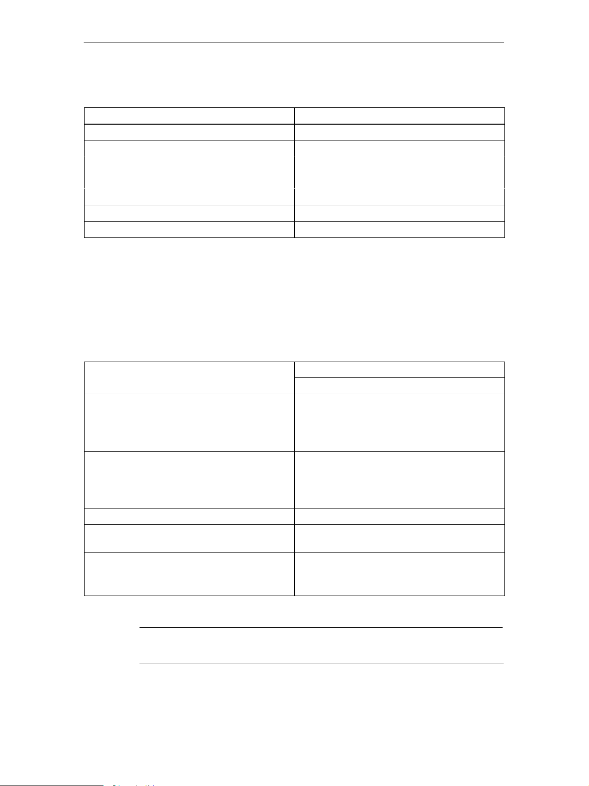
1.6 Front Panel − Access to all Functions
Connection, Display and Control Elements
On the front panel, you have access to all the connection, display and control
elements of the IE/AS-i LINK module.
C-PLUG
Display
LED “LINK” 1
connection to
Ethernet partner
LAN connector
X1
(independent
switch port)
LED “RX/TX” 1
data traffic with
Ethernet partner
LED “LINK” 2
connection to
Ethernet partner
LAN connector
X2
(independent
switch port)
LED “RX/TX” 2
data traffic with
Ethernet partner
(optional)
LEDs
IE/AS-i LINK
SF = system fault
BF = bus fault
ON = power
LEDs
AS-i line
SF = system fault AS-i
APF = AS-i power fail
CER = configuration error
AUP = autoprog available
CM = configuration mode
ON = AS-i online
Keypad
for
− AS-i configuration
− Link configuration
− Diagnostics
X = placeholder
for hardware
version
Firmware version
Figure 1-2 Front View of the IE/AS-INTERFACE LINK PN IO
IE/AS−INTERFACE LINK PN IO as of hardware version 1, as of firmware version V2.0
Release 08/2018
C79000−G8976−C216−03
Power supply
connector 24 V DC
(as alternative to
supply over line 1)
Release catch
for
DIN rail mounting
(bottom of device)
AS-i line 1
connector
AS-i line 2
connector
(only with
double master)
19
1 Technical Description, Installation Guidelines, Operation
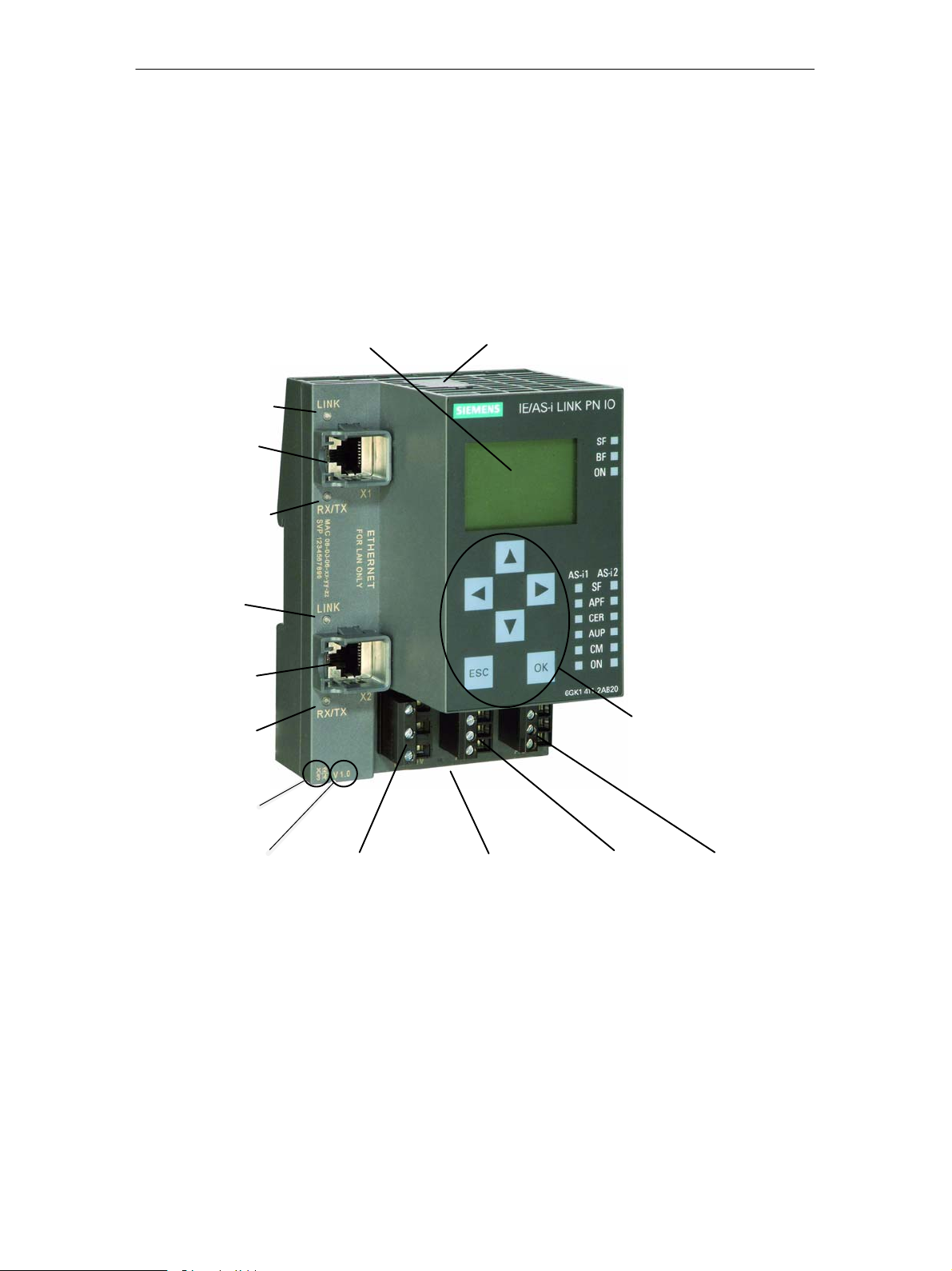
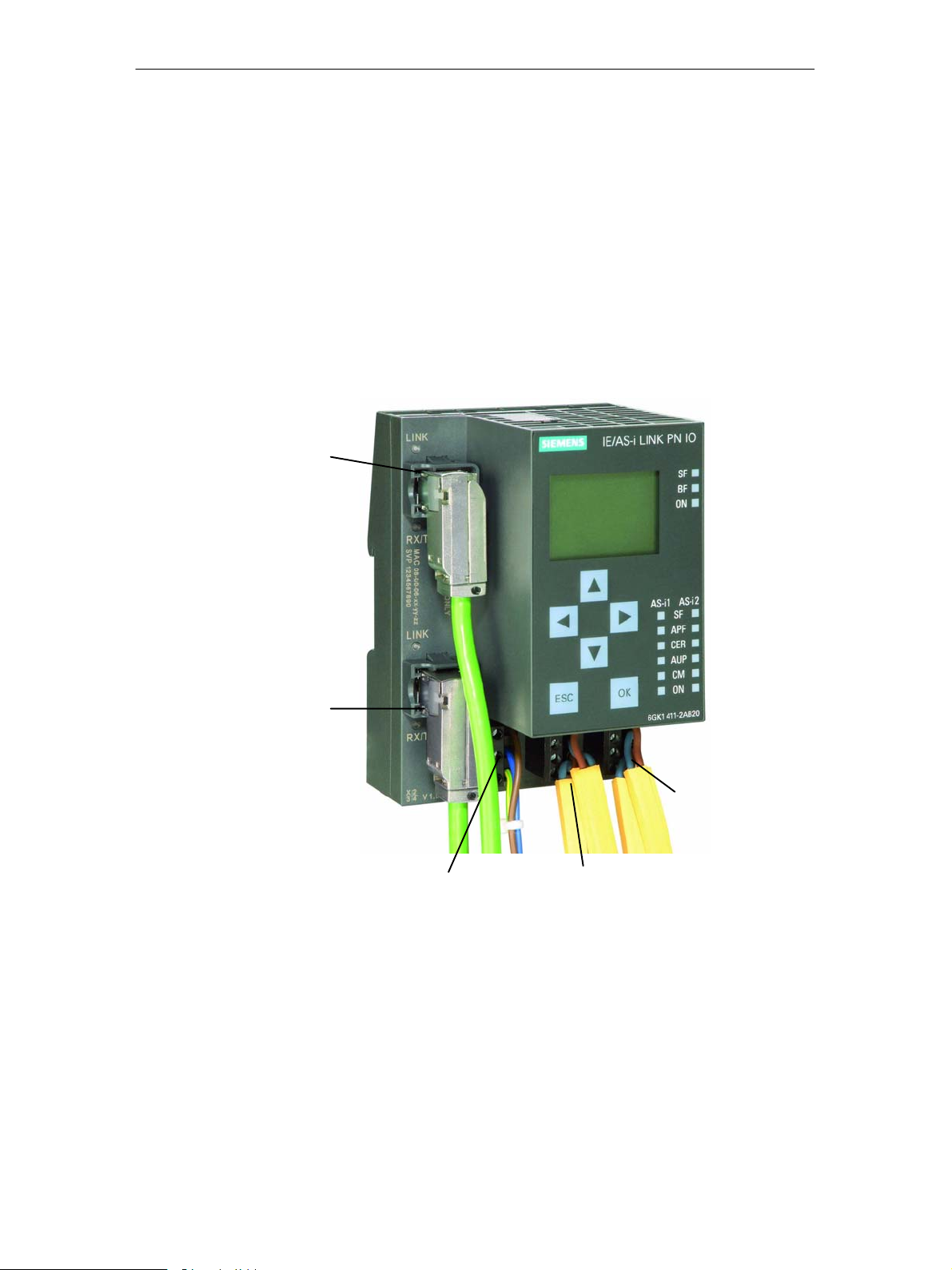
1.7 Connection Elements
Connectors
The IE/AS-i LINK has the following connectors:
S Two separate connectors for the AS-i cable (on double master)
S One connector for alternative power supply 24 V DC (optional) and functional
earthing
S Two RJ-45 LAN connectors as independent switch ports
LAN
connector 1
LAN
connector 2
Power supply
connector 24 V DC
(alternative)
Figure 1-3 Connectors for the AS-i Cable(s) and Power Supply
AS-i line 1
connector
(power supply from
AS-i line 1)
AS-i line 2
connector
(only with
double master)
20
IE/AS−INTERFACE LINK PN IO as of hardware version 1, as of firmware version V2.0
C79000−G8976−C216−03
Release 08/2018
1 Technical Description, Installation Guidelines, Operation
1.7.1 Connectors for the AS-i Cable(s) and Power Supply
Caution
!
!
Connectors for the AS-i Cable(s)
When connecting up the module, keep to the installation guidelines in Section 1.5.
Caution
The IE/AS-INTERFACE LINK PN IO may only be connected when the AS-i power
supply unit is turned off.
The IE/AS-i LINK has two connectors for the AS-i cables (line 1 and line 2). Each
is connected over a 4-pin plug with two + and two − contacts that are jumpered
internally.
This allows the IE/AS-i LINK to be looped into the AS-i cable.
Caution
!
The permitted current loading of the AS-i connection contacts is 3 A. If this value
is exceeded on the AS-i cable, the IE/AS-INTERFACE LINK PN IO must not be
looped into the AS-i cable but must be connected with a tap line (only one pair of
connectors of the IE/AS-i LINK is used).
Pin assignment of the AS-i line
PIN no. line 1 Signal
1 AS-i 1 +
2 AS-i 1 −
3 AS-i 1 +
4 AS-i 1 −
Pins 1 and 3 and pins 2 and 4 are jumpered internally.
PIN no. line 2 Signal
1 AS-i 2 +
2 AS-i 2 −
3 AS-i 2 +
4 AS-i 2 −
IE/AS−INTERFACE LINK PN IO as of hardware version 1, as of firmware version V2.0
Release 08/2018
C79000−G8976−C216−03
21
1 Technical Description, Installation Guidelines, Operation
Power Supply from the AS−Interface
Caution
!
The AS-i power supply unit used and the optional external power supply must
provide an extra low voltage safely isolated from the mains supply. This safe
isolation can be implemented according to the following requirements:
S VDE 0100 Part 410 = HD 384-4-4 = IEC 364-4-41
(as functional extra-low voltage with safe isolation) or
S VDE 0805 = EN60950 = IEC 950
(as safety extra-low voltage SELV) or
S VDE 0106 Part 101
The IE/AS-i LINK can be supplied fully from the AS-Interface (only AS-i line 1). The
current consumption from the AS-Interface is 320 mA at 30 V.
As an alternative, the IE/AS-i LINK can be supplied by a separate power supply
unit (24 V DC).
Power Supply from external Power Supply
Warning
!
The device is designed for operation with safety extra−low voltage (SELV). This
means that only safety extra−low voltages (SELV) complying with
IEC950/EN60950/ VDE0805 may be connected to the power supply terminals.
The power unit for supplying the device must comply with NEC Class 2 as described by the National Electrical Code(r) (ANSI/NFPA 70).
The power of all connected power units in total must correspond to a limited power
source (LPS).
Never operate the IE/AS-INTERFACE LINK PN IO with AC current or DC current
higher than 32 V.
With a double master, you require a separate power unit each for AS−i line 1 + 2.
If the cable to the external power unit is very long and liable to energy spikes,
connect a surge protection element.
Pin assignment of the power supply
PIN no. line 1 Signal
1 Power +
2 Power −
3 PE
22
IE/AS−INTERFACE LINK PN IO as of hardware version 1, as of firmware version V2.0
C79000−G8976−C216−03
Release 08/2018
1 Technical Description, Installation Guidelines, Operation
Note
Functional earthing
IE/AS-INTERFACE LINK PN IO has a connector for functional earthing. This
connector is required if the integrated ground fault monitoring is used. It should be
connected to the PE conductor with as little resistance as possible.
LAN Connectors (PROFINET IO, PC with WBM)
As connectors for PROFINET and a PC (or network) there are two RJ-45 jacks
(recommendation: 90° FC connector).
One LAN connector is intended for the PROFINET system, the second LAN
connector of the IE/AS-i LINK is used, for example, for configuration with Web
Based Management and for diagnostics. The two LAN connectors have equal
status.
The IE/AS-i LINK supports autocrossing, in other words, both crossover and
straight-through cables can be used.
Pin Assignment of the LAN Connector
Pin no. Signal
1 RXP
2 RXN
3 TXP
4 n.c.
5 n.c.
6 TXN
7 n.c.
8 n.c.
n.c. = not connected
IE/AS−INTERFACE LINK PN IO as of hardware version 1, as of firmware version V2.0
Release 08/2018
C79000−G8976−C216−03
23
1 Technical Description, Installation Guidelines, Operation
1.8 C-PLUG (Configuration Plug)
Area of Application
The C-PLUG (order number: 6GK1 900-0AB00) is an optional exchangeable
medium for saving the configuration and project engineering data of the basic
device (IE/AS-i LINK) and the AS-i slaves.
When powered down, the C-PLUG retains all data permanently. This means that
configuration data remains available when a basic device is replaced (module
replacement without PG is therefore possible).
The C-PLUG is accessible from the top of the housing.
The IE/AS-i LINK has internal memory for permanent storage of the configuration
data of the basic device and the AS-i slaves. Replacing a module without a PG is,
however, possible only with the C-PLUG.
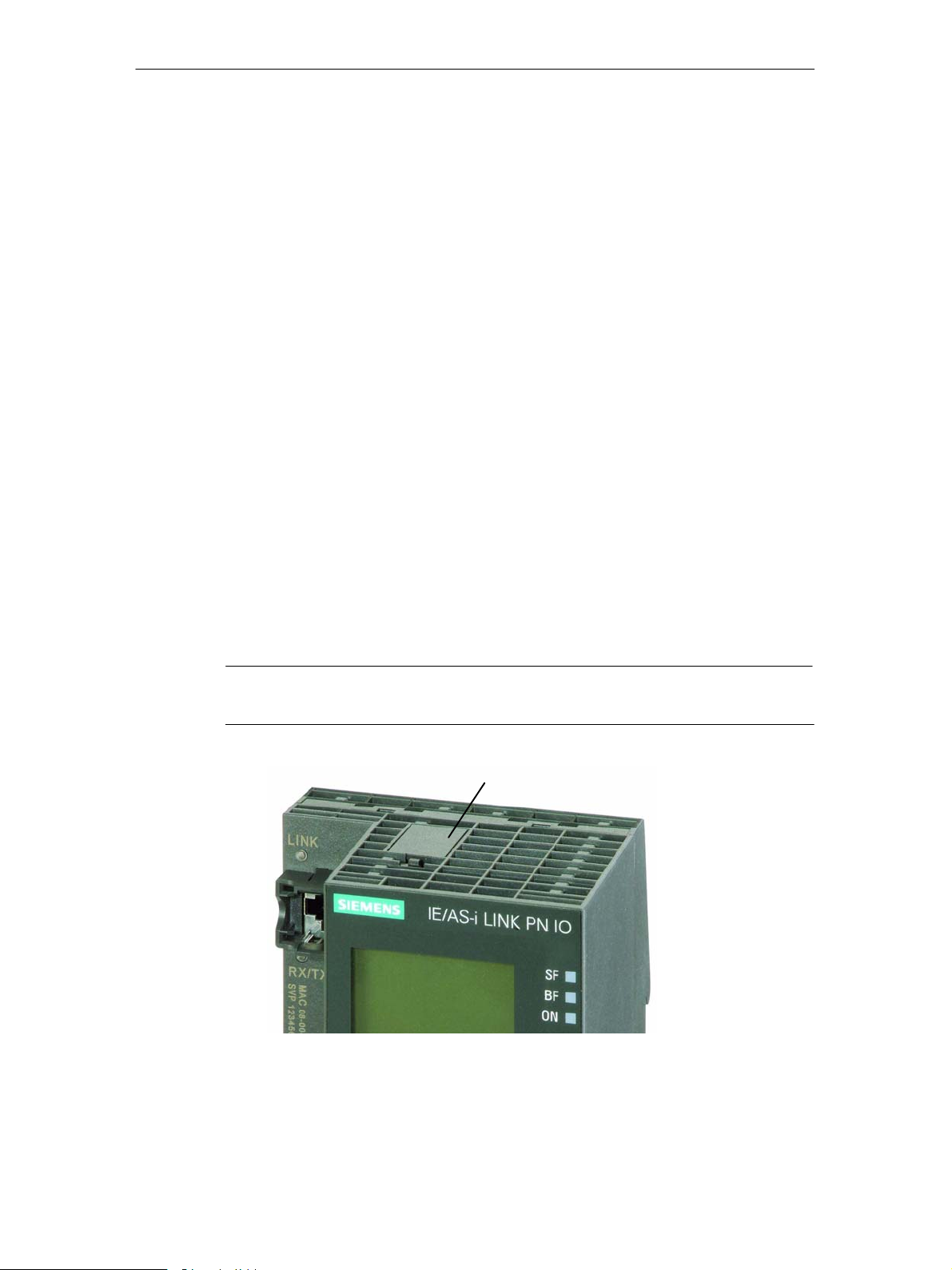
Inserting in the C-PLUG Slot
The slot for the C-PLUG is on the top panel of the device.
To insert the C-PLUG, the cover of the receptacle must be removed. The C-PLUG
is inserted in the receptacle. The cover must then be replaced over the receptacle
and closed correctly.
Notice
The C-PLUG may only be inserted or removed when the power is off!
Cover of the receptacle
for the C-PLUG
Figure 1-4 Position of the C-PLUG (removing the C-PLUG from the device with a screwdriver)
24
IE/AS−INTERFACE LINK PN IO as of hardware version 1, as of firmware version V2.0
C79000−G8976−C216−03
Release 08/2018

Function
1 Technical Description, Installation Guidelines, Operation
If an empty C-PLUG (as supplied) is inserted, all the configuration data of the
IE/AS-i LINK is written to it when the device starts up. Changes to the
configuration during operation are also written automatically to the C-PLUG.
If the C-PLUG is inserted, the basic device automatically uses the configuration
data of the C-PLUG. This assumes that the data was written by a compatible
device type.
If a fault occurs, the basic device can then be replaced much faster and more
simply. If a device needs to be replaced, the C-PLUG is simply taken from the
failed component and inserted in the replacement. As soon as it starts up, the
replacement automatically has the same device configuration as the failed device.
Notice
If a C-PLUG is inserted when you reset to the factory settings, the factory settings
are stored on the C-PLUG !
Using the C-PLUG
When using a C-PLUG, the following situations must be distinguished:
S Inserting an empty C-PLUG:
The IE/AS-i LINK detects when a C-PLUG is inserted and automatically writes
the data of the internal memory to the C-PLUG.
S Inserting a C-PLUG of a different device type:
If you insert a C-PLUG that is not intended for the IE/AS-i LINK, this can also
be used. The IE/AS-i LINK signals an error and changes to the error state
(WBM and display, see also Section 5.2.7).
To clear the problem, the message must be acknowledged. At the same time,
this triggers the transfer of the data from the internal memory to the C-PLUG.
S Inserting the C-PLUG of another IE/AS-i LINK:
If a C-PLUG with valid data of another IE/AS-i LINK is inserted, the device
changes to operational (starts up with the data of the C-PLUG). The data from
the internal memory is, however, not transferred automatically to the C-PLUG.
The transfer must be triggered manually using the keypad and display (or
WBM) (System > Configuration > C-PLUG > Internal memory > C-PLUG; see
Section 4.4). The next time the module starts up, the internal memory is
deleted.
IE/AS−INTERFACE LINK PN IO as of hardware version 1, as of firmware version V2.0
Release 08/2018
C79000−G8976−C216−03
25
1 Technical Description, Installation Guidelines, Operation
1.9 Display and Control Elements
LED Displays
The following LED displays are located on the front panel of the IE/AS-i LINK:
S Displays for the LAN connectors (separate for X1 and X2)
− LINK: Connection to Ethernet partner
− RX/TX: Data traffic
S Displays of the IE/AS-i LINK
− SF: system fault
− BF: bus fault
− ON: Power supply IE/AS-i LINK
S Displays for the AS-i line
− SF: AS-i system fault
− APF: AS-i power fail
− CER: configuration error
− AUP: automatic address programming
− CM: configuration mode
− ON: AS-i status online / offline
Meaning of the IE/AS-i LINK LEDs
LED (color) Status Meaning
SF (red) System fault
(link)
The LED is lit in the following situations:
S In protected mode, a diagnostic interrupt (entering state) was
triggered on the PROFINET IO controller.
S The IE/AS-i LINK has detected an internal error (for example
EEPROM defective).
BF (red) Bus fault The LED flashes in the following situations:
S The connection between the PROFINET IO controller and the
IE/AS-i LINK has broken down or the PROFINET IO controller is
not active.
S IE/AS-i LINK was not or was incorrectly assigned parameters by
the PROFINET IO controller.
ON (green) The LED is lit when the IE/AS-i LINK is supplied with power.
IE/AS−INTERFACE LINK PN IO as of hardware version 1, as of firmware version V2.0
26
C79000−G8976−C216−03
Release 08/2018
1 Technical Description, Installation Guidelines, Operation
Meaning of the AS-i Line LEDs
LED (color) Status Meaning
SF (red) System fault
(line)
APF (red) AS-i Power Fail This indicates that the voltage supplied to the AS-i cable by the AS-i
The LED is lit when a diagnostic interrupt (entering state) was
triggered by the PROFINET IO controller in protected mode.
power supply unit is too low or is faulty.
CER (yellow) Configuration
Error
This LED indicates whether the slave configuration detected on the
AS-i cable matches the expected configuration on the
DP/AS-INTERFACE LINK Advanced. If they do not match, the “CER”
LED is lit.
The “CER” LED is lit in the following situations:
S A configured AS-i slave does not exist on the AS-i cable (for
example failure of the slave).
S An AS-i slave exists on the AS-i cable but it was not previously
configured.
S An attached AS-i slave has different configuration data (I/O
configuration, ID code) from the slave configured on the IE/AS-i
LINK.
S The IE/AS-i LINK is in the offline mode.
AUP (green) Autoprog
available
CM (yellow) Configuration
Mode
In the protected mode of the IE/AS-i LINK module, the LED indicates
that automatic address programming of an AS-i slave is possible. The
automatic address programming makes it much easier to exchange a
defective AS-i slave on the AS-i cable (for more detailed information
refer to Section 10.1).
This LED displays the mode of the IE/AS-i LINK.
S Indicator on: configuration mode
S Indicator off: protected mode
The configuration mode is only required for installing and starting up
the IE/AS-i LINK module. In the configuration mode, the IE/AS-i LINK
activates all connected AS-i slaves and exchanges data with them.
For more information about the configuration mode, refer to Section
4.1.
ON (green) The LED lights up when the AS-i line is operated “Online” (the
AS-i master sends AS-i frames).
In the following situations, the LED goes off:
S when the AS-i line is operated “Offline” (the AS-i master does not
send AS-i frames).
S when no I/O modules were configured for the line in HW Config
IE/AS−INTERFACE LINK PN IO as of hardware version 1, as of firmware version V2.0
Release 08/2018
C79000−G8976−C216−03
27
1 Technical Description, Installation Guidelines, Operation
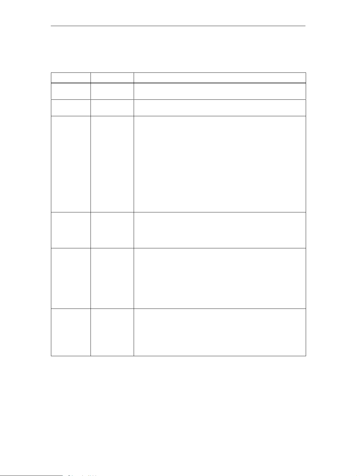
Keypad
The mode can be changed using the control buttons. You configure the underlying
AS-i line interactively with the display using the control buttons.
The following buttons are located on the front panel of the IE/AS-i LINK:
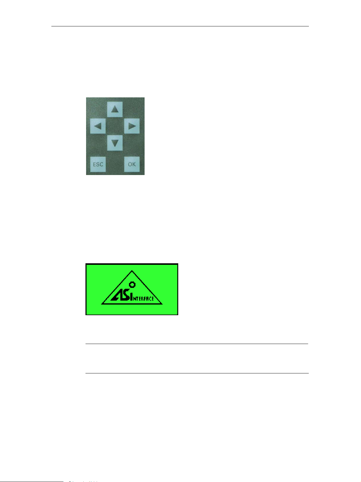
Display
The graphic display has a resolution of 128 x 64 pixels.
You configure the underlying AS-i line using the keypad and the display. This
allows on-site commissioning and diagnostics.
The following display appears after turning on the device and if there has been no
input over the keypad for a longer period of time (see Section 4.4).
Figure 1-5 Display − Logo
Note
If a fault occurs during operation, the resulting error message will be displayed
even if the Logo was previously displayed.
28
IE/AS−INTERFACE LINK PN IO as of hardware version 1, as of firmware version V2.0
C79000−G8976−C216−03
Release 08/2018

1 Technical Description, Installation Guidelines, Operation
As soon as any entry is made using the keypad, the main menu appears allowing
you to navigate through the menu structure.
Figure 1-6 Display − Main Menu
If you have selected an entry in the list (displayed inversely), a tooltip will appear
after a brief time with further information on the entry (does not occur in the main
menu).
1.10 Settings when Using a Firewall
Please note the following when using firewalls:
Note
When using a firewall access to the following ports must be permitted depending
on the service being used:
S http Port 80/TCP (for WBM)
S TFTP Port 69
S SNMP Port 161/UDP
S SNTP Port 123 (can be changed)
S SMTP Port 25
S Trap Port 162/UDP
-
IE/AS−INTERFACE LINK PN IO as of hardware version 1, as of firmware version V2.0
Release 08/2018
C79000−G8976−C216−03
29

1 Technical Description, Installation Guidelines, Operation
1.11 Restrictions due to broadcast or multicast communication
The IE/AS-i LINK PN IO is designed for operating on PROFINET networks where
the configured participants are connected and communicate error-free. It is
imperative to prevent high levels of broadcast or multicast communication on the
PROFINET network.
Notice
If the level of broadcast or multicast communication is too high, the Ethernet
interface of the IE/AS-i LINK can become overloaded, resulting in data
transmission delays, or even device failure.
Broadcast or multicast communication arises when the PROFINET controller is
looking for PROFINET nodes, for example. The search is periodically repeated,
especially when configured PROFINET nodes are not available on the PROFINET
network. Depending on the PROFINET controller and its settings, it is possible that
the communication cycle time is subject to significant fluctuations.
This scenario can occur during step-by-step commissioning of a PROFINET
network. Broadcast or multicast communication can be reduced by adapting the
network configuration to the actual design, e.g. via STEP 7 hardware configuration
or by calling the SFC "D_ACT_DP" SIMATIC system function (Deactivate/activate
distributed I/O devices; SFC 12) in the user program.
Distributing the PROFINET or Ethernet nodes into separate networks can also
reduce broadcast or multicast communication.
Broadcast or multicast communication usually also arises when other network
devices such as computers or PCs are connected to the Ethernet network.
Using SCALANCE managed Industrial Ethernet switches also makes it possible to
limit broadcast or multicast communication at the IE/AS-i Link by filtering Ethernet
communication.
30
IE/AS−INTERFACE LINK PN IO as of hardware version 1, as of firmware version V2.0
C79000−G8976−C216−03
Release 08/2018
 Loading...