

Siemens SIMATIC NET CP 243-1 IT, CP 243-1 IT Technical Manual
back
SIMATIC NET
CP 243-1 IT
Communications Processor
for Industrial Ethernet and
Information Technology
Foreword
Product Information
Table of Contents
List of Figures
List of Tables
Introduction
Features and Functions
Installation and Comissioning
Configuration
Programming
Diagnosis
Appendix A: Technical Data
Appendix B: Example
Technical Manual
Appendix C: Timeouts
03/2003
J31069-D0429-U001-A0-7618

Copyright © Siemens AG 2003 All rights reserved
Passing on and reproduction of this document, or utilization and
revelation of its contents is prohibited without express permission.
Violators will be prosecuted. All rights reserved, particularly in case a
patent is granted or a utiliy model is registered.
Siemens AG
Automation & Drives
Postfach 4848
D-90327 Nuernberg
Siemens-Aktiengesellschaft J31069-D0429-U001-A0-7618
Exclusion of liability
Although we have checked the contents of this publication for
correspondence to the hardware and software described therein, we
cannot guarantee total agreement. The information in this publication is
reviewed at regular intervals and necessary corrections included in the
next releases.
Your suggestions are welcome.
Subject to change without prior notice

Classification of safety information
This document contains information which you must adhere to for your own personal safety and to avoid property damage. This information is highlighted with a
warning triangle and graded by degree of danger.
Danger
!
!
!
means that death or severe injury will occur if appropriate precautions are not
taken.
Warning
means that death or severe injury may occur if appropriate precautions are not
taken.
Caution
with a warning triangle means that minor injury may occur if appropriate precautions
are not taken.
Caution
Brands
without a warning triangle means that property damage may occur if appropriate
precautions are not taken.
Attention
means that an undesired result or state may occur if appropriate precautions are
not taken.
Note
indicates important information on the product, its handling or the particular part of
the documentation requiring special attention. Possible benefits make it advisable
to adhere to these recommendations.
SIMATIC, SIMATIC NET, SINEC and SIMATIC NET Networking for Industry®
are registered brands of Siemens AG.
The other designations in this publication may be brands whose use by third parties for their own purposes may violate the rights of the owners.

Safety information on your product
Before you begin using the product described here, it is essential to read and adhere to the following safety information.
Qualified personnel
Only qualified personnel may commission and operate this device. For the purpose
of the safety notes in this manual, qualified personnel are those persons who are
authorized to commission, ground and tag devices, systems and electrical circuits
according to the standards of safety technology.
Intended use of hardware products
Adhere to the following information on the intended use of hardware products.
Caution
The device may only be used for the technical applications described in the catalog and only with products of Siemens or recommended by Siemens or devices
and components of other manufacturers which have been approved by Siemens.
Correct, safe operation of the product depends on correct transportation, correct
storage, installation and mounting as well as careful operator control and maintenance.
Before you begin using the included sample program or your own programs, make
sure that no injury or property damage to man or machine can occur on the running systems.
EG note: Commissioning is prohibited until it can be determined that the machine
in which these components is to be installed meets the specifications of guideline
89/392/EWG.

03/03 Foreword
Foreword
Purpose of this manual
This manual will be helpful when you use your CP 243-1 IT communications processor. It provides you with information on how to communicate with this communications processor via Industrial Ethernet and how to use the Information Technology functions.
Prerequisites
A knowledge of this manual as well as the manual on SIMATIC S7-200 programmable controllers is required for understanding the functions of the CP 243-1 IT. In
addition, you will need a basic knowledge of such topics as TCP/IP, FTP, E-Mail,
HTML, Web Browser and Java.
Target group
This manual is written for engineers, programmers, commissioning personnel and
maintenance personnel with a general knowledge of automation and communication systems as well as user interface systems.
Sample program
This manual contains a sample program which gives you an example of how to
program your CP 243-1 IT. This program was prepared with STEP 7-Micro/WIN 32
V3.2.3 and will run on an S7-200 CPU (type 224). If you want to run this sample
program on another S7-200 CPU, you may have to adjust this CPU to the configuration expected by our program.
CP 243-1 IT
J31069-D0429-U001-A0-7618
5

Product Information 03/03
Product Information
Address label: MAC address
The CP 243-1 IT is delivered with a permanently set MAC address. This MAC address is shown on a label underneath the upper covering flap of the device.
MLFB number, scope of delivery
Product Name MLFB Scope of Delivery
CP 243-1 IT 6GK7 243-1GX00-0XE0 CP, documentation on CD-ROM
CP 243-1 IT
6
J31069-D0429-U001-A0-7618

03/03 Table of Contents
Table of Contents
Foreword ........................................................................................................... 5
Product Information .........................................................................................6
List of Figures................................................................................................. 10
List of Tables .................................................................................................. 11
1 Introduction ............................................................................................ 13
2 Features and Functions......................................................................... 15
2.1 Overview ............................................................................................................15
2.2 S7 Communication via Industrial Ethernet......................................................... 17
2.2.1 Preliminary Comments ....................................................................................... 17
2.2.2 Types of Communication ...................................................................................18
2.2.3 Communication Partners ................................................................................... 18
2.3 IT Communication .............................................................................................. 23
2.3.1 Preliminary Remarks.......................................................................................... 23
2.3.2 Types of Communication ...................................................................................24
2.3.3 E-Mail ................................................................................................................. 25
2.3.4 FTP Server......................................................................................................... 27
2.3.5 FTP Client ..........................................................................................................29
2.3.6 HTTP Server ......................................................................................................33
2.4 File System ........................................................................................................ 37
2.5 User Administration............................................................................................ 39
2.6 Security ..............................................................................................................41
2.6.1 Configuration...................................................................................................... 41
2.6.2 Data Security...................................................................................................... 42
2.6.3 Communication Security .................................................................................... 42
2.7 Connections .......................................................................................................43
2.8 Indicators: Front LEDs ....................................................................................... 44
3 Installation and Commissioning ........................................................... 47
3.1 Dimensions for Installation in a Control Panel ...................................................50
3.2 Dimensions for Installation on a DIN Rail .......................................................... 50
3.3 Installation in a Control Panel ............................................................................51
3.4 Installation on a Standard DIN Rail.................................................................... 52
3.5 Replacement Parts............................................................................................. 53
CP 243-1 IT
J31069-D0429-U001-A0-7618 7

Table of Contents 03/03
3.6 Demounting the CP 243-1 IT .............................................................................54
4 Configuration.......................................................................................... 55
4.1 Possible Configurations .....................................................................................55
4.2 Value Ranges of the Configuration Data ........................................................... 57
4.2.1 IP Addresses...................................................................................................... 57
4.2.2 Subnet Mask ...................................................................................................... 57
4.2.3 TSAPs ................................................................................................................ 57
4.2.4 Ports................................................................................................................... 58
4.2.5 E-Mail Tags ........................................................................................................ 58
4.3 Configuration of a CP 243-1 IT with STEP 7 Micro/WIN 32 ............................. 60
4.3.1 Basic Configurations ..........................................................................................61
4.3.2 Configuration of User Administration ................................................................. 65
4.3.3 Configuration of the E-Mail Functions................................................................ 65
4.3.4 Configuration of the FTP Functions ................................................................... 66
4.3.5 Conclusion of Configuration ............................................................................... 67
4.4 Additional Ways to Configure a CP 243-1 IT ..................................................... 67
4.4.1 Assigned System Marker Area (SM Area) ......................................................... 69
4.4.2 Structure of Configuration Data Block (CDB) ....................................................70
4.4.3 Structure of the Network Parameter Block (NPB).............................................. 74
4.4.4 Structure of the Network Data Block (NDB)....................................................... 74
4.4.5 Structure of the Internet Data Block (IDB) .........................................................76
4.4.6 Structure of the Configuration File for User Administration (.udb File) ............. 79
4.4.7 Structure of the Configuration File for the E-Mail Client (.edb File) .................. 82
4.4.8 Structure of the Configuration File for the FTP Client (.fdb File) ....................... 85
4.5 Configuration of a Communication Partner with STEP 7................................... 89
4.6 Reaction of the CP 243-1 IT to Configuration Errors ......................................... 93
5 Programming.......................................................................................... 95
5.1 ETHx_CTRL....................................................................................................... 96
5.2 ETHx_CFG......................................................................................................... 98
5.3 ETHx_XFR ......................................................................................................... 99
5.4 ETHx_EMAIL ................................................................................................... 101
5.5 ETHx_FTPC..................................................................................................... 103
6 Diagnosis .............................................................................................. 107
6.1 Diagnostic Capabilities ..................................................................................... 107
6.2 Error Messages of the CP 243-1 IT .................................................................111
6.2.1 Error Messages in Byte Format ....................................................................... 112
6.2.2 Error Messages in Word Format...................................................................... 116
6.3 Error Messages of the Test Routine for E-Mails .............................................. 119
CP 243-1 IT
8
J31069-D0429-U001-A0-7618

03/03 Table of Contents
Appendix A Technical Data ...................................................................... 121
Appendix B Example ................................................................................. 123
Appendix C Timeouts................................................................................ 131
Abbreviations................................................................................................ 133
CP 243-1 IT
J31069-D0429-U001-A0-7618 9

List of Figures 09/02
List of Figures
Fig. 1 System overview .....................................................................................................19
Fig. 2 Overview of the IT functions.................................................................................... 23
Fig. 3 Connections ............................................................................................................ 43
Fig. 4 Front with the LEDs................................................................................................. 44
Fig. 5 Space requirements during installation ................................................................... 49
Fig. 6 Dimensions for installation in a control panel.......................................................... 50
Fig. 7 Dimensions for installation on a DIN rail .................................................................50
Fig. 8 Screen "Properties – S7 connection" ...................................................................... 90
Fig. 9 Calling the subprogram ETHx_CTRL...................................................................... 96
Fig. 10 Call of the subprogram ETHx_CFG ........................................................................ 98
Fig. 11 Call of the subprogram ETHx_XFR....................................................................... 100
Fig. 12 Call of the subprogram ETHx_EMAIL ................................................................... 102
Fig. 13 Call of the subprogram ETHx_FTPC ....................................................................104
CP 243-1 IT
10
J31069-D0429-U001-A0-7618

03/03 List of Tables
List of Tables
Table 1 Predefined HTML pages ......................................................................................... 36
Table 2 Directory structure of the CP 243-1 IT ...................................................................38
Table 3 Length of the user names and passwords .............................................................. 40
Table 4 Function of the individual LEDs............................................................................... 45
Table 5 Examples of formatting instructions for placeholders in e-mails............................. 59
Table 6 System marker area ................................................................................................ 69
Table 7 Structure of the CDB ............................................................................................... 73
Table 8 Structure of the NPB ............................................................................................... 74
Table 9 Structure of the NDB ............................................................................................... 76
Table 10 Configuration of the read/write jobs ........................................................................ 76
Table 11 Structure of the IDB................................................................................................. 78
Table 12 Structure of the configuration file for user administration........................................ 79
Table 13 Structure of the parameter record of a user............................................................ 80
Table 14 Structure of the configuration file for the e-mail client............................................. 83
Table 15 Structure of the configuration file for the FTP client ................................................ 85
Table 16 Structure of the parameter record for an FTP job ................................................... 87
Table 17 Input parameters (ETHx_CTRL) ............................................................................. 96
Table 18 Return parameters (ETHx_CTRL) .......................................................................... 97
Table 19 Input parameters (ETHx_CFG) ............................................................................... 98
Table 20 Return parameters (ETHx_CFG) ............................................................................ 99
Table 21 Input parameters (ETHx_XFR) ............................................................................. 100
Table 22 Return parameters (ETHx_XFR)........................................................................... 101
Table 23 Input parameters (ETHx_EMAIL).......................................................................... 102
Table 24 Return parameters (ETHx_EMAIL) ....................................................................... 102
Table 25 Input parameters (ETHx_FTPC) ........................................................................... 104
Table 26 Return parameters (ETHx_FTPC) ........................................................................ 105
CP 243-1 IT
J31069-D0429-U001-A0-7618 11

List of Tables 03/03
Table 27 Addressing of global errors and module information ............................................ 108
Table 28 Layout of the NPB memory area........................................................................... 109
Table 29 Error messages in byte format .............................................................................. 115
Table 30 Error messages in word format ............................................................................. 118
Table 31 Error messages for test routine for e-mails ........................................................... 119
Table 32 Technical data ....................................................................................................... 122
Table 33 Timeouts on Ethernet ............................................................................................ 131
Table 34 Timeouts on the backplane bus ............................................................................ 132
CP 243-1 IT
12
J31069-D0429-U001-A0-7618

03/03 Introduction
1 Introduction
Definition and application
The CP 243-1 IT is a communications processor designed for use in an S7-200
programmable controller. It permits an S7-200 system to be connected to Industrial
Ethernet (IE). This makes communication via Ethernet possible even in the lower
performance class of the S7 product family. Using STEP 7 Micro/WIN 32, an S7200 can be configured, programmed and diagnosed via Ethernet even at a geographical distance. Using a CP 243-1 IT, an S7-200 can communicate via Ethernet
with another S7-200, S7-300 or S7-400 controller. Communication with an OPC
server is also possible.
The IT functions of the CP 243-1 IT form the basis for monitoring and, if necessary,
also manipulating automation systems with a Web browser from a networked PC.
In addition, diagnostic messages can be e-mailed from a system. Using the IT
functions, it is very easy to exchange entire files with other computer and controller
systems.
Industrial Ethernet is the network for the process control level and the cell level of
the SIMATIC NET open communication system. Physically, Industrial Ethernet is
an electrical network based on shielded, coaxial lines, twisted pair cabling and an
optical network of fiber optic conductors. Industrial Ethernet is defined by the international standard IEEE 802.3.
Continuous communication in the industrial area - worldwide
Industrial Ethernet is embedded in the SIMATIC NET concept which permits continuous networking of process control level, cell level and field level with
PROFIBUS and AS Interface. The IT functions, characterized by their worldwide
uniform standards and protocols, serve as the bridges between the world of industrial controllers and the typical PCs used by the office world of today.
Compatibility
The CP 243-1 IT (6GK7 243-1GX00-0XE0) described here can be used for S7
communication. The CP 243-1 IT can be connected to various types of S7-200
CPUs (222, 224, 226 and 226XM).
• CPU 222 rel. 1.10 or higher
• CPU 224 rel. 1.10 or higher
• CPU 226 rel. 1.00 or higher
• CPU 226XM rel. 1.10 or higher
A maximum of 2 expansion modules can be installed on the CPU 222. In contrast,
up to 7 expansion modules can be connected to CPUs 224, 226 and 226XM.
The CP 243-1 IT is fully compatible with the CP 243-1. This means that user programs which were written for the CP 243-1 can also be run on a CP 243-1 IT.
CP 243-1 IT
J31069-D0429-U001-A0-7618 13

Introduction 03/03
Caution
Only one CP 243-1 or one CP 243-1 IT may be connected per S7-200 CPU. If additional CP 243-1 or CP 243-1 IT processors are connected, the S7-200 system
may no longer function correctly.
The software of the CP 243-1 IT is compatible with the following standards.
• S7 XPUT/XGET and S7 READ/WRITE
• S7-200 I/O bus specification
• HTTP 1.0 in acc. w. RFC1945
• FTP in acc. w. RFC959
• SMTP in acc. w. RFC2821/2822 (only functions for sending e-mails)
Configuration
The CP 243-1 IT is configured with STEP 7 Micro/WIN 32 starting with version
3.2.3. The standard CP 243-1 IT is delivered with a fixed MAC address. IP address and subnet mask must be configured or obtained from a BOOTP server.
Programming
Use the Internet wizard of STEP 7 Micro/WIN 32 to program communication in the
user program (see chapters 4 and 5).
Configuration
The firmware of the CP 243-1 IT is programmed on flash memory during production and is stored there permanently. System states or dynamic variables which
occur during operation of the CP 243-1 IT are not stored permanently.
Configuration of the CP 243-1 IT is divided into Industrial Ethernet and IT services.
The Ethernet configuration is retentively stored in the DB of the S7-200 CPU. During startup, the CP 243-1 IT reads the configuration from the CPU and initializes itself accordingly.
The configuration of the IT services is stored in the file system of the CP 243-1 IT
in the form of one configuration each for user administration, FTP client and e-mail
service. These configuration files are continuously evaluated during running operation.
CP 243-1 IT
14
J31069-D0429-U001-A0-7618

03/03 Features and Functions
2 Features and Functions
2.1 Overview
The CP 243-1 IT offers the following functions.
• S7 communication
− Performance data communication via Industrial Ethernet. Communication
is based on standard TCP/IP.
− Ethernet access via RJ45 socket
− Easy connection to an S7-200 system via the S7-200 backplane bus
− Permits flexible and distributed automation structure
− Basis for simple further processing and archivation of process data
− Permits simultaneous communication with up to eight S7 controllers
− Offers a link to S7-OPC
− Simple network administration
− S7 communication services "XPUT/XGET" as client and server
− S7 communication services "READ/WRITE" as server
− For Keep Alive connection checks, a time can be configured for all TCP
transport connections with active and passive partners.
• IT communication
− File system for permanent storage of Web and configuration files on the
CP 243-1 IT
− SMTP client for sending e-mails. In addition to pure text information, embedded variables can also be transmitted. The current value of such a
variable is not determined until the e-mail is sent.
− Configuration of up to 32 e-mails with up to 1024 characters each
− FTP server for access to the file system of the CP 243-1 IT
− FTP client for exchanging data with an FTP server
− Configuration of up to 32 FTP client operations
− The FTP client function supports the commands READ, WRITE and DE-
LETE.
− Access of the FTP client to the FTP server of the CP 243-1 IT
− HTTP server for the read and write access to process and status data of
the S7-200 system via up to four Web browsers at one time
− Prepared HTML pages for diagnosis of the S7-200 system and for access
to process variables
− Sending a test e-mail via a prepared HTML page
CP 243-1 IT
J31069-D0429-U001-A0-7618 15

Features and Functions 03/03
− Storage of own HTML pages and Java Applets in the file system of the CP
243-1 IT
− Provision of Java Applets and Beans for development of own HTML pages
and Java Applets
− User administration for up to 8 users with user-specific granting of rights for
access to files, status information and process variables.
• Configuration
− Programming, configuring and diagnosing an S7-200 system from a geo-
graphical distance (e.g., program upload and download or status indications) via Industrial Ethernet and STEP 7 Micro/WIN 32
− Exchanging modules possible without having to program/configure the
Ethernet functions again (Plug & Play). Since the configuration of the IT
functions is stored on the CP 243-1 IT, this must be loaded again to the
module when the CP 243-1 IT is replaced.
• Watchdog timer
The CP 243-1 IT is equipped with a watchdog circuit. The watchdog starts each
time the CP 243-1 IT boots. The watchdog monitoring time is usually 5 seconds.
Tolerances due to components may increase this time to 7 seconds. If watchdog monitoring triggers, the CP 243-1 IT is automatically reset. This restarts the
CP 243-1 IT. During this time, the CP 243-1 IT reports the "Parity Error" to the
S7-200 CPU. Handling such an error is described in the documentation of
STEP 7 Micro/WIN 32.
• Ability of preset MAC addresses (48-bit value) to be addressed
The MAC address is assigned to each CP 243-1 IT at the plant. The MAC address is located on an adhesive plate under the upper front flap. An IP address
can be assigned to the CP 243-1 IT via the preset MAC address using BOOTP.
CP 243-1 IT
16
J31069-D0429-U001-A0-7618

03/03 Features and Functions
2.2 S7 Communication via Industrial Ethernet
2.2.1 Preliminary Comments
S7 communication via Industrial Ethernet permits program-controlled communication via communication SFBs/FBs and configured S7 connections. The CP 243-1
IT supports S7 communication via Industrial Ethernet with the XPUT/XGET and
READ/WRITE services. Up to 212 bytes of user data can generally be transmitted
per job. If the CP 243-1 IT is run as server, up to 222 bytes of user data can even
be transferred in read jobs.
The CP 243-1 IT supports a maximum of eight S7 communication channels to clients or servers on one or more geographically removed communication partners.
The CP 243-1 IT works on the client/serve principle for each channel. Only one job
at a time per channel is accepted, processed and answered with a positive or
negative response. Not until a response has been sent does the CP 243-1 IT accept a new job.
If the CP 243-1 IT receives several jobs on a channel configured as server, only
the first job is processed. The subsequent jobs are ignored until the end of the
transaction (i.e., until a response is sent). The CP 243-1 IT has no channel-specific
job administration and does not buffer jobs.
Prerequisites for communication with a PC/PG
As before, a PG/PC can access the S7-200 CPU via the PPI interface. In addition,
this access may take place via the CP 243-1 IT via Ethernet. The following prerequisites must be fulfilled for this.
• An Ethernet card is installed and configured on the PG/PC and an Ethernet or
TCP/IP connection to the CP 243-1 IT exists (via routers, firewalls, and so on).
• STEP 7 Micro/WIN 32 (starting with version 3.2.3) is installed on the PG/PC.
• The CP 243-1 IT has a valid address. This address may be permanently speci-
fied in the configuration or obtained from a BOOTP server.
At this time, only one STEP 7 Micro/WIN 32 can communicate via a CP 243-1 IT
with the S7-200 CPU. Use of the Ethernet interface is mandatory for configuration
of the IT services.
CP 243-1 IT
J31069-D0429-U001-A0-7618 17

Features and Functions 03/03
2.2.2 Types of Communication
The CP 243-1 IT has three types of S7 communication relationships which can be
used individually and in combination.
1. Coupling with STEP 7-Micro/WIN 32
2. Coupling with other, geographically remote components of the SIMATIC S7
family
3. Coupling with OPC-based applications on a PC/PG
2.2.3 Communication Partners
• S7-200 CPU with CP 243-1 or CP 243-1 IT
• S7-300 CPU with CP 343-1 or CP 343-1 IT
• S7-400 CPU with CP 443-1 or CP 443-1 IT
• PG/PC with OPC server
• PG/PC with STEP 7 Micro/WIN 32
The STEP 7 HW-Config program shows you the types of S7-300 CPUs and S7400 CPUs which support the S7 protocol XPUT/XGET (i.e., can communicate with
the CP 243-1 IT). When you select an S7-300 or S7-400 CPU in the catalog box
there, this CPU must support the function "S7 communication."
With systems from the S7-300 family, an XPUT/XGET client can only be used with
a related communications processor starting with version 1.1. You will find the version of your communications processor in the MLFB number, among others. If you
are using a CP 343-1, the MLFB number must contain the character string "EX11"
or higher.
Always remember that the CP 243-1 IT does not support pure ISO connections.
Since the CP 443-1 ISO has neither TCP/IP nor RFC 1006, it is not able to communicate with a CP 243-1 IT.
Caution
Only one CP 243-1 or one CP 243-1 IT may be connected to an S7-200 CPU. If
additional SP 243-1 or CP 243-1 IT processors are connected, the S7-200 system
may not function correctly.
Note
Concerning communication with an OPC server, remember that the CP 243-1 IT
does not support automatic querying of the objects (e.g., DBxx, and so on) on the
S7-200.
A CP 243-1 IT can only communicate with an OPC server when this server supports the two S7 services READ and WRITE.
CP 243-1 IT
18
J31069-D0429-U001-A0-7618
03/03 Features and Functions
Overview
S7-200
PC
BOOTP-
Server
max. 8 x
xput / xget read / write
...
CPU 22x
CP 243-1/IT
S7-200 S7-300 S7-400
CPU 22x
CPU 3xx
...
CP 243-1 IT
......
CP 343-1/IT
1 x
PC
Micro/WIN
Ethernet
OPC-Server
CPU 4xx
......
CP 443-1/IT
OPC-Client
PC
Fig. 1 System overview
A CPU 22x with CP 243-1 IT can communicate both with other S7-200, S7-300
and S7-400 systems and with an OPC server. A maximum of 8 connections (see
Fig. 1) are possible in addition to a STEP 7 Micro/WIN connection.
Configuring and programming connections for S7 stations
To configure communication between an S7-200 and an S7-300, S7-400 or an
OPC server, you will need both STEP 7 Micro/WIN 32 (starting with version 3.2.3)
and STEP 7 (starting with version 5.1 with service pack 3 or higher, with NCM for
Industrial Ethernet).
The S7-200 station is configured and programmed with STEP 7 Micro/WIN 32. You
will need STEP 7 with NCM for Industrial Ethernet to configure and program the
S7-300 or S7-400 or the OPC server.
CP 243-1 IT
J31069-D0429-U001-A0-7618 19

Features and Functions 03/03
Data communication via Industrial Ethernet
Data communication via the CP 243-1 IT is based on Ethernet and is thus not deterministic (i.e., specific response times are not guaranteed). 10 and 100-Mbit networks are supported in full and half-duplex.
In addition, the CP 243-1 IT supports the auto-negotiation function for automatically
negotiating the operating mode and the transmission speed to be used. The mode
and the transmission speed can also be permanently specified by the user when
configuring the CP 243-1 IT. If the CP 243-1 IT doesn't have a valid configuration, it
always uses "auto-negotiation" mode.
Note
Auto-negotiation mode only works when all connected network components support this mode.
Industrial Ethernet and TCP/IP do not allow time-deterministic data flow. There is
no way to know when a geographically remote CPU will execute the requested
jobs. The responses of the geographically removed CPU are asynchronous to the
CPU cycle of the local S7-200 CPU. This is why TCP/IP-based communication is
only partly suitable for use in widespread applications with time requirements (e.g.,
control circuits, cyclic precisely timed scanning).
CP 243-1 IT
20
J31069-D0429-U001-A0-7618

03/03 Features and Functions
S7 communication
The XPUT and XGET S7 services are used to communicate data between two
controllers. The CP 243-1 IT can be used both as client and as server.
Communication between a CP 243-1 IT and an OPC server running on a PC/PG
uses the READ and WRITE S7 services. The CP 243-1 IT is always the server
here. Other S7 services (e.g., the service for automatic scanning of objects on an
S7-200 - DBs, and so on) are not supported.
The following data types or data areas are supported by the CP 243-1 IT.
CP 243-1 IT as client
Read and write accesses
• Data type is always BYTE.
• Only variables can be accessed on the local system.
• Accessible memory areas on the partner system are inputs, outputs, markers
and variables with an S7-200 as partner.
• Accessible memory areas on the partner system are inputs, outputs, markers
and data areas with an S7-300 or an S7-400 as partner.
CP 243-1 IT a server
Write accesses
• Data type is BOOL, BYTE, WORD or DWORD.
• Use of data types CHAR, INT, DINT and REAL depends on the firmware status
of the S7-200 CPU being used.
• Accessible memory areas on the local system are inputs, outputs, variables,
markers and status bits.
Read accesses
• Data type is BOOL, BYTE, WORD or DWORD.
• Use of data types CHAR, INT, DINT and REAL depends on the firmware status
of the S7-200 CPU being used.
• Accessible memory areas on the local system are inputs, outputs, variables,
markers, system area and status bits.
Note
When an S7-300 or S7-400 is the server on a client running on an S7-200 system,
the CP 243-1 IT expects this server to always behave passively. This means that,
in such cases, the S7-300 or S7-400 system is not allowed to send S7 jobs to the
S7-200 system.
Communication with STEP 7 Micro/WIN 32
With communication between a CP 243-1 IT and STEP 7 Micro/WIN 32, the CP
243-1 IT is always the server. STEP 7 Micro/WIN 32 is always the client here.
CP 243-1 IT
J31069-D0429-U001-A0-7618 21

Features and Functions 03/03
Backplane bus communication
All accesses to all data areas of the S7-200 CPU are always possible. The read
and write accesses are not dependent on whether the CPU is in RUN, TERM or
STOP status.
CP 243-1 IT
22
J31069-D0429-U001-A0-7618
03/03 Features and Functions
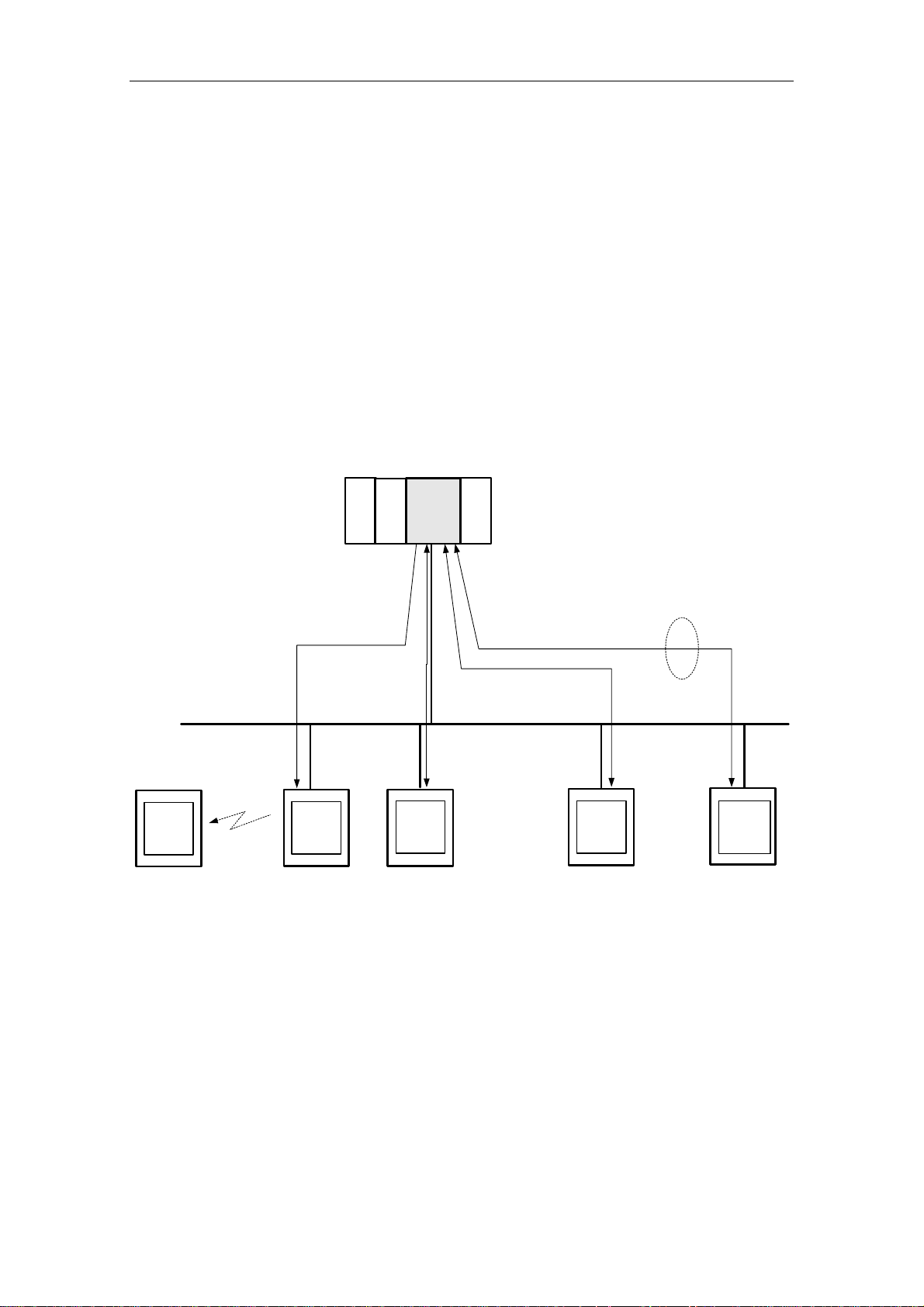
2.3 IT Communication
2.3.1 Preliminary Remarks
In addition to S7 communication via Industrial Ethernet, the CP 243-1 IT also supports the services XPUT/XGET and READ/WRITE parallel to a variety of IT functions. These include data communication via FTP, sending e-mails, and the capability of permitting up to four Web browsers to access data and status information
on the S7-200 system at the same time. See Fig. 2.
Sending an e-mail or active file access via FTP are initiated by the S7-200 user
program. Only one job at a time can be active for each of these two functions. Not
until the CP 243-1 IT has positively or negatively acknowledged the job can the
user program start another job.
S7-200
E-MailServer
PC
Handy
PC
E-Mail-
Server
SMTP
CPU 2xx
...
FTP
FTP-
Client
PC
S7-200
S7-300
S7-400
...
CP 243-1 IT
Fig. 2 Overview of the IT functions
HTTP
PC
S7-200
S7-300
S7-400
FTP
FTP-
Server
4x
Ethernet
HTTP-
Browser
PC
CP 243-1 IT
J31069-D0429-U001-A0-7618 23

Features and Functions 03/03
2.3.2 Types of Communication
In addition to the S7 communication relationships described in chapter 2.2.2, the
CP 243-1 IT offers four types of IT communication relationships which can be used
individually or in combination.
1. Communication with an e-mail server
2. Communication with an FTP client located in a geographically remote system
3. Communication with an FTP server. Such a server is usually located in a geographically remote system. However, a coupling to the FTP server running on
the CP 243-1 IT of the local S7-200 system is also possible.
4. Communication with up to four Web browsers running on geographically remote
systems
CP 243-1 IT
24
J31069-D0429-U001-A0-7618

03/03 Features and Functions
2.3.3 E-Mail
How it works
The SMTP protocol controls the transmission of e-mails. An e-mail consists of one
or two address fields, a subject field and a field for the actual text message.
The text message consists of ASCII characters. The text may contain placeholders
for variables which reference a data value of the local S7-200 system. When the email is sent, the CP 243-1 IT reads each such value from the local S7-200 CPU
and inserts it in the desired format at the specified location in the message. The CP
243-1 IT makes it possible to send e-mails preconfigured by a user program to an
e-mail server already specified via IP address and an port during the configuration
phase. The e-mail server then sends the e-mail to the e-mail recipient specified in
the address field of the e-mail.
The e-mail server specified in the configuration by an IP address and a port number must be located in the subnetwork of the CP 243-1 IT or be able to be accessed via a gateway. If this e-mail server cannot be accessed, the e-mail is sent
to a substitute e-mail server which is also specified when the CP 243-1 IT is configured. If this substitute e-mail server is also not accessible, an appropriate error
message is generated.
Caution
The CP 243-1 IT only monitors whether an e-mail could be delivered to the configured e-mail server. It is unable to tell whether this e-mail was forwarded to and
read by the specified recipient.
Note
Since memory areas of the S7-200 CPU must be read out in accordance with the
configuration when an e-mail is sent, a reset in between or power failure of the S7200 CPU may cause the e-mail transmission to be terminated altogether before it
can even be sent.
This means that a message that an S7-200 CPU reset has occurred cannot be
sent via e-mail.
The CP 243-1 IT does not support the receipt of e-mails. The e-mails and the address parameters of the e-mail server are configured by STEP 7 Micro/WIN 32.
CP 243-1 IT
J31069-D0429-U001-A0-7618 25

Features and Functions 03/03
Note
Before e-mails can be sent from the CP 243-1 IT, you must make sure that a functioning e-mail server can be accessed from there.
General accessibility of an e-mail server can be tested with the HTML page
"sendmail.htm," among others, which is included with the CP 243-1 IT (see chapter
2.3.6).
Configuration
Configuration of the e-mails and the address parameters of the e-mail server is
performed with the Internet wizard of STEP 7 Micro/WIN 32. The configuration data
entered here are stored permanently in a file with the ending .edb in the file system
of the CP 243.1 IT. Transmission of these data from the system on which the configuration was prepared with STEP 7 Micro/WIN 32 to the CP 243-1 IT is handled
via FTP.
Up to 32 e-mails can be configured. Each e-mail text may consist of up to 1024
characters.
The structure of each e-mail is shown below.
− E-mail number
This number can be used to reference a configured e-mail by the S7-200
user program.
− Receiver address
The e-mail address of the receiver. This address must always be specified.
− Additional receiver address
The address of a recipient who is to receive a copy of the e-mail. This address does not have to be specified.
− Subject
A short description of the e-mail. The subject must always be specified.
− E-mail text including placeholders and formatting characters. The actual in-
formation to be transferred is located here.
Each address field may only contain one receiver address. When an e-mail is to be
sent to several recipients, a distribution list must be set up on the e-mail server and
this list must be specified as the e-mail receiver.
In addition to the control characters for the placeholders of data values, the following format characters are supported in the e-mail text.
− \n Line feed
− \t Tabulator
CP 243-1 IT
26
J31069-D0429-U001-A0-7618

03/03 Features and Functions
Note
The maximum length of the e-mail text of 1024 characters refers to the actual message text including all embedded placeholders and all format characters ("\n" and
"\t").
If the maximum permissible length of 1024 characters is exceeded by resolution of
the placeholders when an e-mail is sent, the e-mail text is truncated after 1024
characters and an appropriate error message is returned. The truncated e-mail is
then transferred, however.
Conversion procedures such as MIME or UUENCODE are not supported. In addition, files cannot be appended to e-mails.
The e-mail function of the CP 243-1 IT can always be activated or deactivated with
the configuration.
Communication partners
In addition to conventional PCs, all terminals with e-mail capability are in principle
possible e-mail recipients (e.g., cell phones or FAX machines).
Performance/general conditions
Sending of e-mails is subordinate to S7 communication.
Reaction times when sending an e-mail depend on the configuration and cannot be
specified in general. The greater the number of simultaneous S7 connections and
the larger the amount of data to be transmitted over these connections, the longer
it takes to process and send e-mails.
Caution
The placeholders embedded in the e-mail text are read out individually from the
S7-200 CPU. Only one such value can be transferred per S7 cycle from the S7200 CPU to the CP 243-1 IT. This means that the time needed to set up an e-mail
depends on the amount of data to be included, the cycle time of the S7-200 CPU
and the load of the backplane bus.
2.3.4 FTP Server
How it works
The FTP server of the CP 243-1 IT can be used, among others, to transfer Web
files and configuration files from a geographically remote FTP client via Ethernet to
the file system of the CP 243-1 IT and to read them there.
In this case, the FTP client always initiates the data transfer. The FTP server of the
CP 243-1 IT never initiates FTP transmissions itself.
CP 243-1 IT
J31069-D0429-U001-A0-7618 27

Features and Functions 03/03
All types of files can be transferred to the file system of the CP 243-1 IT. Relevance of these files to operation of the CP 243-1 IT is not checked.
Caution
BINARY-type transmission should be used to transfer files between the FTP server
of the CP 243-1 IT and a geographically remote FTP client. The transmission type
must be set on the FTP client side.
Note
Since the CP 243-1 IT does not provide the time, the files stored on or read from
the CP 243-1 IT via FTP all have the date 01.01.1980 and the time 00:00.
Access protection
FTP is a protocol for which the user must authenticate himself before gaining access to the FTP server. This requires a user name and a password which is valid
on the server. After a connection between the FTP client and the FTP server of the
CP 243-1 IT is established, the user name and related password must be entered.
After successful authentication, the user can then access the file system of the CP
243-1 IT. He can move through the directory tree, transmit files and manage directories.
Up to 8 users as well as an administrator can be configured for the CP 243-1 IT.
The administrator is distinguished from the up to 8 users with special rights and the
location at which the fixed user name and the related password are stored.
The user names and passwords are configured with STEP 7 Micro/WIN 32. The
configuration file created by the Internet wizard to be used here is transferred with
FTP to the CP 243-1 IT and stored permanently in the file system there in a file
with the ending .udb. The user name and the password of the administrator are required before the user configuration can be transferred to the CP 243-1 IT.
Note
The CP 243-1 IT does not support an FTP access without specification of a user
name or password.
Auto logout
Simultaneous access of several FTP clients to the FTP server of the CP 243-1 IT is
not supported.
The FTP server is equipped with an auto logout routine to prevent it from being
blocked by an undefined connection termination of an FTP client.
If the FTP server located on the CP 243-1 IT is connected with an FTP client and a
second FTP client wants to establish a connection to the FTP server, the server
checks to determine whether there was FTP-based communication between it and
the first FTP client during the last 60 seconds. If not, the connection to the fist FTP
client is disconnected and the second FTP client's request to establish a connection is accepted. Otherwise, the connection to the first FTP client is continued and
the second FTP client's request for a connection is rejected.
CP 243-1 IT
28
J31069-D0429-U001-A0-7618

03/03 Features and Functions
Supported FTP commands
After the HELP command is entered in the console box of the FTP client, a list of
the FTP commands supported by this client usually appears. While these commands are being executed, they can then be converted internally by the FTP client
into subcommands and sent to the FTP server.
Some FTP clients on the market offer additional commands which are not included
in the RFC959 standard or whose specification is not generally binding. You cannot be sure whether the FTP server on the CP 243-1 IT supports each of these
commands.
Communication partners
All FTP clients which communicate via Ethernet and which comply with RFC959
standards are always considered possible communication partners of the FTP
server located on the CP 243-1 IT. This means communication is not only possible
with PC-based FTP clients but also with S7-200, S7-300 or S7-400-supported FTP
clients, for instance.
Performance/general conditions
FTP communication is subordinate to S7 communication. This means that the reaction times of FTP communication depend on the particular configuration and
cannot be generally specified in advance.
Note
Only one FTP client may access the FTP server at a time. When the FTP server of
the CP 243-1 IT is accessed by the S7 user program via the FTP client function, a
geographically remote FTP client cannot be accessed. The reverse also applies.
2.3.5 FTP Client
How it works
The FTP client of the CP 243-1 IT can be used to transfer parts of the DB in an S7200 system to the file system of an FTP server, or the contents of a file can be copied there to the DB of the local S7-200 system.
A distinction can be made as to whether a file is to be completely or only partially
transferred. The number of bytes to be transmitted can be specified in a read or
write job.
When 0 is specified as the number of bytes to be transferred in a write job, an
empty file with the name specified in the write job is set up in the file system of the
addressed FTP server. A length of 0 in a read job means that the specified file is
completely transmitted to the DB of the local S7-200 system if this does not exceed
its storage space. If the number of bytes to be read is specified for a read job, this
must match the length of the file to be read. If not, the CP 243-1 IT reports an error
when the read job is executed.
CP 243-1 IT
J31069-D0429-U001-A0-7618 29

Features and Functions 03/03
With the help of the FTP client, it is possible to delete files in the file system of an
FTP server from the local S7-200 system.
During the transmission with FTP, the files to be exchanged are not changed and
the data therein are not converted. All data to be transferred are treated as if they
were in byte format. The data to be written are stored by byte in the specified file.
The FTP client of the CP 243-1 IT always initiates the file transfer, triggered by the
S7-200 user program. An FTP server itself does not generate FTP requests.
The CP 243-1 IT only accepts one FTP client request from the S7-200 user program at a time. As soon as this is completely processed, the CP 243-1 IT prepares
a positive or negative acknowledgment. Not until this happens can the S7-200 user
program issue a new FTP client job.
The FTP servers specified in the configuration with their IP address must be located in the subnetwork of the CP 243-1 IT or must be accessible via a gateway.
Caution
The data transferred from or to the memory of the S7-200 CPU via FTP are transmitted in binary mode. There is no conversion or formatting of these data. The data
to be transferred are not stored permanently on the CP 243-1 IT.
Configuration
The FTP jobs are configured with the Internet wizard of STEP 7 Micro/WIN 32. The
configuration data entered here are permanently stored in the file system of the CP
243-1 IT in a file with the ending .fdb. Transmission of these data from the system
on which the configuration was prepared with STEP 7 Micro/WIN 32 to the CP 2431 IT is handled via FTP.
Up to 32 FTP jobs can be predefined with one file transaction each. Each of these
jobs is described with the following parameter record.
− FTP job number
Every configured FTP job can be referenced from the S7-200 user program
with this number.
− IP address on the FTP server
IP address of the system whose file system is to be accessed
− User name on the FTP server
The login on the FTP server takes place under this name. This means that
the name specified here must have access rights for the addressed FTP
server.
− Password for on the FTP server
The encrypted password specified here is used to log in on the FTP server.
− Path name of the applicable file
The file name including the complete path must be specified here.
− Job type to be executed. Possible job types are:
− Write to file system of the FTP server
− Read from file system of the FTP server
− Delete files from file system of the FTP server
CP 243-1 IT
30
J31069-D0429-U001-A0-7618
 Loading...