

Page 1
Preface
Notes on product
Table of contents
List of figures
List of tables
SIMATIC NET
CP 243-1
Communications processor
for Industrial Ethernet
Technical manual
Introduction
Features and functions
Installation and commissioning
Configuration
Programming
Diagnostics
Appendix A: Technical data
Appendix B: Example
Appendix C: Timeout
SIMATIC NET –
Support and training
Page 2

Copyright Siemens AG, 2002, All rights reserved
Passing this document on to third parties, reproducing this
document or using or relating its contents is not permitted without
express authority. Offenders will be liable for damages. All rights,
including rights created by patent grant or registration of a utility
model or design, are reserved.
Siemens AG
Automaton and Drives
Postfach 48 48
D-90327 Nürnberg
Siemens Aktiengesellschaft J31069-D0428-U001-A1-7618
Liability exclusion
We have checked the contents of this Manual to ensure that they
match the hardware and software described herein. However,
because deviations cannot be completely ruled out, we cannot
guarantee complete conformance. The information contained in this
document is checked regularly and any necessary corrections are
included in subsequent editions. We are thankful for any
recommendations or suggestions.
We reserve the right to make technical changes.
Page 3

Classification of safety instructions
This manual contains instructions that should be observed to ensure your personal
safety and to protect the equipment from damage. The instructions are highlighted
in the manual by a warning triangle and are marked as follows according to the
level of danger:
Danger
!
!
!
indicates an imminently hazardous situation which, if appropriate precautions are
not taken, will result in death or serious injury.
Warning
indicates an imminently hazardous situation which, if appropriate precautions are
not taken, may result in death or serious injury
Caution
used with a warning triangle indicates an imminently hazardous situation which, if
appropriate precautions are not taken, may result in minor injury.
Caution
used without a warning triangle indicates an imminently hazardous situation which,
if appropriate precautions are not taken, may result in property damage.
Attention
indicates an imminent situation which, if the instructions are not adhered to, may
result in an undesirable result or state.
Note
highlights an important item of information about the product or its use, or indicates
a section of the instructions that deserves careful attention as it contains information that may be beneficial to the user.
Trademarks
SIMATIC, SIMATIC NET, SINEC and SIMATIC NET Networking for Industry®
are registered trademarks of Siemens AG.
Other designations in this document may be trademarks whose use by third parties
for their own purposes may infringe on the rights of the trademark holder.
Page 4

Safety-related information on the product
Before using the product described here, it is imperative that you observe the following safety-related information.
Qualified personnel
The equipment may be commissioned and operated by qualified personnel only.
For the purposes of the safety instructions in this instruction manual, a Qualified
Person is one who is authorized to commission, ground and label devices, systems
and circuits in accordance with accepted safety standards.
Intended use of hardware products
Please observe the following information regarding the intended use of hardware
products:
Caution
The device may only be used in applications as provided for in the catalog and in the
technical description, and only in connection with non-Siemens products and components that have either been recommended or approved.
Successful and safe operation of this equipment is dependent on proper transport,
handling, storage, erection and installation, as well as careful operation and maintenance.
Before using the supplied sample programs or programs that you created yourself,
ensure that running systems cannot endanger persons or damage machines.
EG regulation: Commissioning is prohibited until it has been established that the machine into which this component is to be installed is in compliance with the regulations
of the 89/392/EWG directive.
Page 5

09/02 Preface
Preface
Purpose of this manual
This manual is designed to support you in using the CP 243-1 communications
processor. You are provided with information on how to employ this communications processor to communicate via Industrial Ethernet (IE).
Prerequisites
A prerequisite for understanding how the CP 243-1 works is familiarity with this
manual and the "SIMATIC S7-200 Automation System" (MLFB: 6ES7298-8FA218AH0) manual. You must also have a basic understanding of the TCP/IP protocol.
Target group
This manual is directed toward engineers, programmers, commissioning engineers
and maintenance technicians with a general knowledge of automation and communication systems and human machine interface systems.
Sample program
This manual contains a sample program that provides you with information and assistance in programming the CP 243-1. This sample program was created with
STEP 7-Micro/WIN 32 (MLFB: 6ES7 810-2BC02-OYXO) and can be run on an S7200 CPU, type 224. To run this sample program on another S7-200 CPU, you may
have to adjust the configuration of the program.
CP 243-1
J31069-D0428-U001-A1-7618
1
Page 6

Notes on product 09/02
Notes on product
Address label: MAC address
The CP 243-1 is delivered with a fixed MAC address. The MAC address is affixed
to the underside of the top cover of the device.
MLFB number, scope of delivery
Product name MLFB Scope of delivery
CP 243-1 6GK7 243-1EX00-0XE0 CP, documentation on CD-ROM
CP 243-1
2 J31069-D0428-U001-A1-7618
Page 7

09/02 Table of contents
Table of contents
Preface............................................................................................................... 1
Notes on product.............................................................................................. 2
List of figures.................................................................................................... 5
List of tables ..................................................................................................... 6
1 Introduction .............................................................................................. 7
2 Features and functions............................................................................ 9
2.1 Overview ..............................................................................................................9
2.2 S7 communication via Industrial Ethernet ......................................................... 10
2.2.1 Application.......................................................................................................... 10
2.2.2 Types of communication ....................................................................................11
2.2.3 Communication partners ....................................................................................11
2.3 Security ..............................................................................................................15
2.3.1 Configuration...................................................................................................... 15
2.3.2 Data security ......................................................................................................16
2.3.3 Integrity of communication ................................................................................. 16
2.4 Connections .......................................................................................................17
2.5 Displays: Front LEDs ......................................................................................... 18
3 Installation and commissioning............................................................ 20
3.1 Dimensions for installation in a control panel .................................................... 24
3.2 Dimensions for installation on a DIN rail ............................................................24
3.3 Installation in a control panel ............................................................................. 25
3.4 Installation on a standard DIN rail...................................................................... 26
3.5 Replacement of the CP 243-1............................................................................ 27
3.6 Removing the CP 243-1..................................................................................... 27
4 Configuration.......................................................................................... 28
4.1 Configuration options .........................................................................................28
4.2 Value ranges of the configuration data ..............................................................30
4.2.1 IP address ..........................................................................................................30
4.2.2 Subnet mask ......................................................................................................30
4.2.3 TSAPs ................................................................................................................ 30
4.3 Configuring a CP 243-1 using STEP 7 Micro/WIN 32 .......................................31
CP 243-1
J31069-D0428-U001-A1-7618
3
Page 8

Table of contents 09/02
4.4 Configuring a CP 243-1 from a user program.................................................... 36
4.4.1 Occupied system flag area (SM area) ...............................................................37
4.4.2 Structure of the Configuration Data Blocks (CDB)............................................. 38
4.4.3 Structure of the Network Parameter Blocks (NPB) ............................................ 42
4.4.4 Structure of the Network Data Blocks (NDB) ..................................................... 43
4.5 Configuring a communication partner with STEP 7 ...........................................45
4.6 Behavior of CP 243-1 in the event of configuration errors ................................. 49
5 Programming.......................................................................................... 50
5.1 ETHx_CTRL....................................................................................................... 51
5.2 ETHx_CFG......................................................................................................... 53
5.3 ETHx_XFR .........................................................................................................54
6 Diagnostics............................................................................................. 57
6.1 Diagnostics options ............................................................................................ 57
6.2 Error messages of the CP 243-1 ....................................................................... 60
Appendix A Technical data......................................................................... 66
Appendix B Example ................................................................................... 67
Appendix C Timeouts.................................................................................. 73
Abbreviations.................................................................................................. 75
SIMATIC NET – Support and training............................................................ 76
CP 243-1
4 J31069-D0428-U001-A1-7618
Page 9

09/02 List of figures
List of figures
Fig. 1. System overview .....................................................................................................12
Fig. 2. Connections ............................................................................................................ 17
Fig. 3. Front with LED displays .......................................................................................... 18
Fig. 4. Space requirements for installation......................................................................... 23
Fig. 5. Dimensions for installation in a control panel.......................................................... 24
Fig. 6. Dimensions for installation on a DIN rail .................................................................24
Fig. 7. "Properties – S7 connection" mask ......................................................................... 46
Fig. 8. Calling the ETHx_CTRL subroutine ........................................................................ 51
Fig. 9. Calling up the ETHx_CFG subroutine..................................................................... 53
Fig. 10. Calling up the ETHx_XFR subroutine ..................................................................... 55
CP 243-1
J31069-D0428-U001-A1-7618
5
Page 10

List of tables 09/02
List of tables
Table 1: Functions of individual LED displays....................................................................... 19
Table 2: System flag area ..................................................................................................... 37
Table 3: CDB structure .......................................................................................................... 41
Table 4: NPB structure .......................................................................................................... 42
Table 5: NDB structure .......................................................................................................... 44
Table 6: Configuration of read/write commands ...................................................................44
Table 7: Input parameters (ETHx_CTRL) .............................................................................51
Table 8: Return parameters (ETHx_CTRL) ..........................................................................52
Table 9: Input parameters (ETHx_CFG) ............................................................................... 53
Table 10: Return parameters (ETHx_CFG) ............................................................................ 54
Table 11: Input parameters (ETHx_XFR) ............................................................................... 55
Table 12: Return parameters (ETHx_XFR)............................................................................. 56
Table 13: Global errors and their error codes ......................................................................... 58
Table 14: Structure of NPB memory areas ............................................................................. 59
Table 15: Error messages (error byte) ....................................................................................63
Table 16: Error messages (error word) ...................................................................................65
Table 17: Technical data ......................................................................................................... 66
Table 18: Timeouts at the Ethernet......................................................................................... 73
Table 19: Timeouts at the S7 bus ........................................................................................... 74
Table 20: Frequently asked questions .................................................................................... 78
CP 243-1
6 J31069-D0428-U001-A1-7618
Page 11

09/02 Introduction
1 Introduction
Definition and application
The CP 243-1 is a communications processor designed for operation in an S7-200
automation system. It is used for connecting an S7-200 system to Industrial
Ethernet (IE). The CP 243-1 also facilitates communication via Ethernet for the
low-end performance range of the S7 product family. As a result, S7-200 can be
remotely configured, programmed and diagnosed via Ethernet using STEP 7 Micro/WIN 32. Moreover, an S7-200 can communicate with another S7-200, S7-300
or S7-400 controller via Ethernet. It can also communicate with an OPC server.
In the open SIMATIC NET communications system, Industrial Ethernet is the network for both the coordination level and the cell level. Technically, the Industrial
Ethernet is an electrical network built on the basis of a shielded coaxial cable,
twisted pair cabling or an optical network using a fiber optic cable. Industrial
Ethernet is defined by the international standard IEEE 802.3.
Continuous communication in the industry sector
Industrial Ethernet is an integral part of the SIMATIC NET concept, which together
with PROFIBUS and the AS Interface ensures continuous networking of the coordination, cell and field levels.
Compatibility
The CP 243-1 (6GK7 243-1EX00-0XE0) described here can be used for S7 communication. The CP 243-1 can be connected to various types of S7-200 CPUs
(222, 224, 226 and 226XM):
• CPU 222 Rel. 1.10 or higher
• CPU 224 Rel. 1.10 or higher
• CPU 226 Rel. 1.00 or higher
• CPU 226XM Rel. 1.00 or higher
A maximum of 2 extension modules can be mounted on the CPU 222. In contrast,
up to 7 extension modules can be connected to the 224, 226 and 226XM CPUs.
Attention
Only one CP 243-1 should be connected per S7-200 CPU. It cannot be guaranteed
that the S7-200 system will operate properly if additional CP 243-1 are connected.
CP 243-1
J31069-D0428-U001-A1-7618
7
Page 12

Introduction 09/02
The CP 243-1 software is compatible with the following standards:
• S7 XPUT/XGET and S7 READ/WRITE
• S7-200 I/O bus specifications
Planning
The CP 243-1 is configured using STEP 7 Micro/WIN 32, version 3.2.1. or higher.
The CP 243-1 is always delivered with a fixed MAC address. The IP address and
the subnet mask either must be configured or they must be retrieved from a
BOOTP server via the BOOTP protocol. For the purpose of monitoring connections
(Keep Alive), a time can be configured for all TCP transport connections with active
and passive partners. A total of 8 connections to other controllers can be maintained at any one time.
Programming
To program the communication in the user program, use the "Ethernet Wizard" in
STEP 7 Micro/WIN 32; see Chapters 4 and 5.
Configuration
The CP 243-1 firmware is programmed into the Flash memory during production
and is permanently stored there.
System conditions or dynamic variable contents that are generated during
CP 243-1 operation do not survive a loss of power.
The CP 243-1 is configured with STEP 7 Micro/WIN 32, version 3.2.1 or higher,
and the configuration is stored in the DB of the S7-200 CPU as non-volatile data.
Upon booting, the CP 243-1 reads the configuration out of the CPU and initializes
itself accordingly.
CP 243-1
8 J31069-D0428-U001-A1-7618
Page 13

09/02 Features and functions
2 Features and functions
2.1 Overview
The CP 243-1 features the following functions:
• S7 communication
− Performant data communication via Industrial Ethernet. Communication is
based on standard TCP/IP
− Ethernet access via an RJ45 socket
− Simple connection to an S7-200 system via the S7-200 backplane bus
− Facilitates a flexible and distributed automation structure
− Remote programming, configuration and diagnostics of an S7-200 system
(e.g. program upload and download or status displays) via Industrial
Ethernet and STEP 7 Micro/WIN 32.
− Basis for simple further processing and archiving of process data
− Enables simultaneous communication with up to 8 S7 controllers
− Provides a connection to S7-OPC
− Simple network administration
− Modules can be exchanged without requiring repeat program-
ming/configuration (plug & play)
− S7 communication services, "XPUT/XGET", as client and server
− S7 communication services, "READ/WRITE", as server
• Watchdog timer
The CP 243-1 is equipped with a Watchdog circuit. The Watchdog starts each
time CP 243-1 starts up. Typically, the Watchdog monitoring time is 5 s. Due to
component-related tolerances, this time can increase to 7 s. If the Watchdog
monitoring time sets in, a reset of the CP 243-1 is automatically brought about.
This restarts the CP 243-1. During this time, the CP 243-1 reports a "Parity Error" to the S7-200 CPU. Handling of this type of error is described in the STEP 7
Micro/WIN 32 documentation.
• Address assignment via preset MAC address (48 bit value).
The MAC address is assigned to each CP 243-1 at the factory. It is printed on a
label affixed to the underside of the upper enclosure cover.
An IP address can be assigned to the CP 243-1 via the preset MAC address using the BOOTP protocol.
CP 243-1
J31069-D0428-U001-A1-7618
9
Page 14

Features and functions 09/02
2.2 S7 communication via Industrial Ethernet
2.2.1 Application
The S7 communication via Industrial Ethernet makes program-controlled communication via communication SFBs/FBs and configured S7 connections possible.
The CP 243-1 supports S7 communication via Industrial Ethernet by means of the
XPUT/XGET and READ/WRITE services. In general, up to 212 bytes of user data
can be transmitted per command. However, if the CP 243-1 is being operated as a
server, up to 222 bytes can be transmitted per read operation.
The CP 243-1 supports up to 8 communication channels to clients or servers on
one or more remote communication partners. The CP 243-1 operates according to
the client/server principle per channel. Per channel, only one command at a time is
received, processed and responded to with a positive or negative response. Only
after a response has been sent will the CP 243-1 accept another command.
If the CP 243-1 receives more than one command on a channel configured as a
server, only the first command is processed and the following commands are ignored until the transaction is completed, i.e. until a response has been sent. The
CP 243-1 is not equipped with channel-specific command management and does
not buffer commands.
Prerequisites for communication with a PC/PG
As before, the S7-200 CPU can still be accessed by a PG/PC via the PPI interface.
In addition, it can also be accessed via the CP 243-1 through Ethernet. The following prerequisites must be met to use this alternative:
− An Ethernet card is inserted in the PG/PC and configured, and there is an
Ethernet or TCP/IP connection to the CP 243-1 (possibly through routers,
firewalls, ...)
− STEP 7 Micro/WIN 32, version 3.2.1 or higher, is installed on the PC/PG.
− The CP 243-1 has been assigned a valid IP address. This address can be
defined in the configuration or retrieved from a BOOTP server via the
BOOTP protocol.
At this time, only one STEP 7 Micro/WIN 32 can communicate with the S7-200
CPU via a CP 243-1.
CP 243-1
10 J31069-D0428-U001-A1-7618
Page 15

09/02 Features and functions
2.2.2 Types of communication
The CP 243-1 is provided with three types of communication relationships that can
be applied either individually or in combination.
1. Connection to STEP 7 Micro/WIN 32
2. Connection to further, remote components of the SIMATIC S7 family
3. Connection to OPC-based applications on a PC/PG
2.2.3 Communication partners
• S7-200 CPU with CP 243-1
• S7-300 CPU with CP 343-1 or CP 343-IT
• S7-400 CPU with CP 443-1 or CP 443-IT
• PG/PC with OPC server
• PG/PC with STEP 7 Micro/WIN 32
In the STEP 7 HW-Config program, you can identify which types of S7-300 CPUs
and S7-400 CPUs support the S7 protocol, XPUT/XGET, and, hence, which ones
can communicate with the CP 243-1. When you select an S7-300 or S7-400 CPU
in the catalog window in the program, the selected CPU must support the "S7
communication" function.
For systems in the S7-300 series, XPUT/XGET can only be operated via Ethernet
with a communications processor of version 1.1 or higher. You can identify the
communications processor version by looking at the MLFB number, among other
things. If you use a CP 343-1, the MLFB number must contain the sequence
"EX11“.
The CP 443-1 ISO cannot communicate with the CP 243-1, since the CP 443-1
ISO do not have TCP/IP and RFC 1006 on board.
Attention
Only one CP 243-1 should be connected per S7-200 CPU. It cannot be guaranteed
that the S7-200 system will operate properly if additional CP 243-1 are connected.
Note
When communicating with an OPC server, it should be noted that the CP 243-1
does not support the service that automatically queries which objects are present
in the S7-200 (e.g. DBxx...).
CP 243-1
J31069-D0428-U001-A1-7618
11
Page 16
Features and functions 09/02
Overview:
S7-200
PC
BOOTP
max. 8 x
xput / xget read / write
...
CPU 22x
CP 243-1
S7-200 S7-300 S7-400
CPU 22x
CPU 3xx
...
CP 243-1
......
CP 343-1/IT
1 x
PC
Micro/WIN
Ethernet
OPC-Server
CPU 4xx
......
CP 443-1/IT
OPC-Client
PC
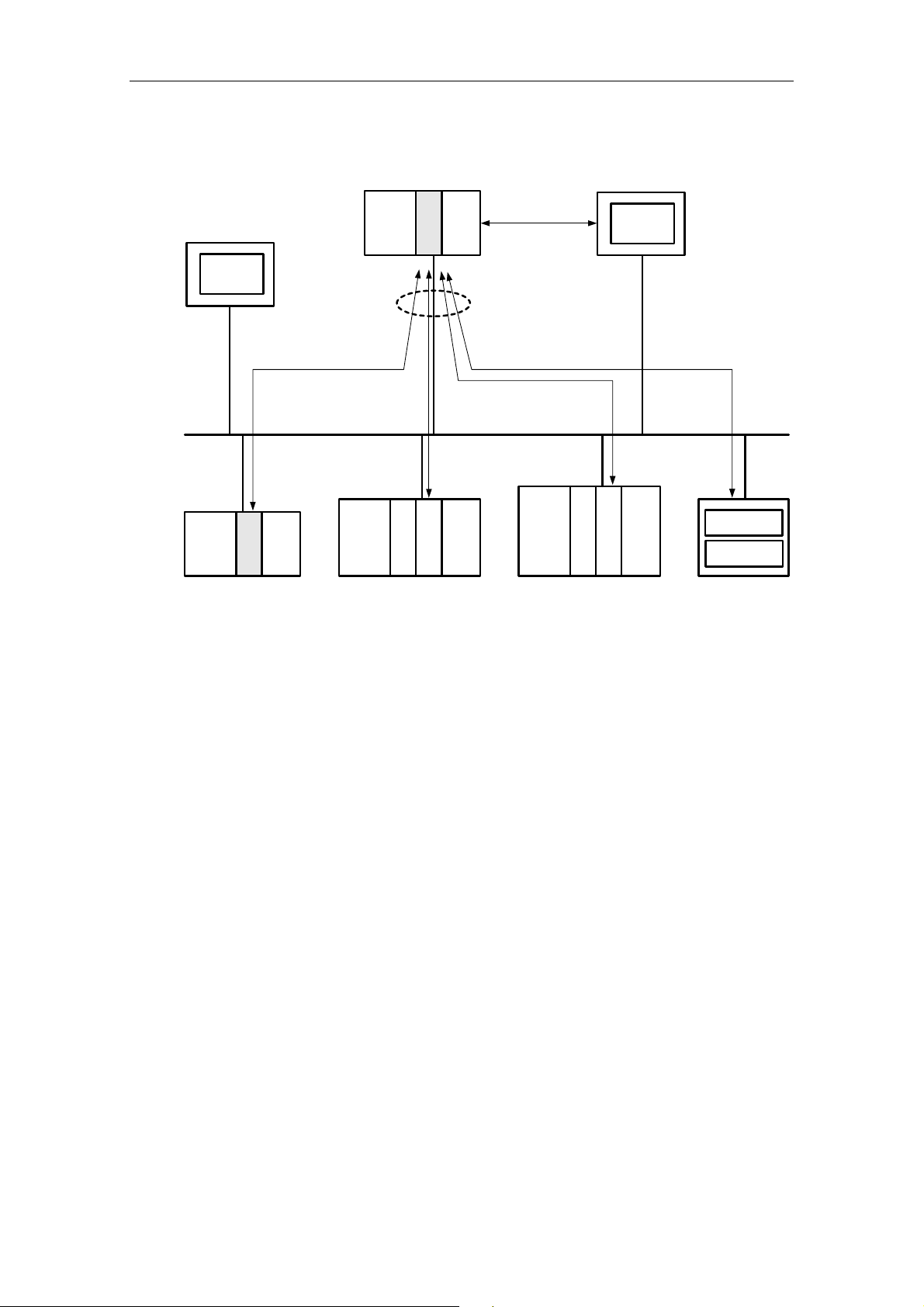
Fig. 1. System overview
You can have a CPU 22x with CP 243-1 communicate with other S7-200, S7-300
and S7-400 systems, as well as with an OPC server.
In this case, a maximum of 8 connections are possible in addition to a STEP 7 Micro/WIN connection (see Fig. 1).
Configuring and programming connections for S7 stations
In order to configure the communication between an S7-200 and an S7-300,
S7-400 or OPC server, you will require both STEP 7 Micro/WIN 32, version 3.2.1 or
higher, and STEP 7, version 5.1 or higher, with Service Pack 3 or higher (with NCM
for Industrial Ethernet) (see Chapter 4.5).
STEP 7 Micro/WIN 32 is used for configuring and programming the S7-200 station,
while STEP 7 with NCM for Industrial Ethernet is required for configuring and programming the S7-300, S7-400 or the OPC server.
CP 243-1
12 J31069-D0428-U001-A1-7618
Page 17

09/02 Features and functions
Data exchange via Industrial Ethernet
The exchange of data via the CP 243-1 is based on Ethernet and is therefore not
deterministic, i.e. response times cannot be guaranteed. Network support is provided for 10 and 100 Mbit networks, each in full-duplex and half-duplex mode.
Furthermore, the CP 243-1 supports the "Auto Negotiation" function for the automatic negotiation of the mode and the transmission rate to be used. The mode and
the transmission rate can also be defined by the user when configuring the
CP 243-1. If the CP 243-1 was not provided with a valid configuration, it always
uses the “Auto Negotiation“ mode by default.
Note
The Auto Negotiation mode only operates if all connected network components
support this mode.
Industrial Ethernet and TCP/IP do not permit time-deterministic data flows. It cannot be predicted at what time a remote CPU will execute the requested commands.
The responses from the remote CPU are asynchronous to the CPU cycle of the local CPU. Therefore, TCP/IP-based communication has only limited suitability for
distributed applications with time-related requirements (e.g. control loop, periodic
sampling).
CP 243-1
J31069-D0428-U001-A1-7618
13
Page 18

Features and functions 09/02
S7 communication
The S7 services, XPUT and XGET, are used for data exchange between two controllers. Here, the CP 243-1 can be implemented as both a client and a server.
Communication between a CP 243-1 and an OPC server running on a PC/PG is
based on the S7 services, READ and WRITE. In this case, the CP 243-1always
acts as the server. Other S7 services, such as the service that automatically queries which objects are currently present in an S7-200 (DBs, ...), are not supported.
The following data types or data areas are supported by the CP 243-1:
CP 243-1 as client:
Read and write access:
• The data type is always BYTE
• Only variables can be accessed on the local system.
• The memory areas that are accessible on the partner system when an S7-200
is acting as a partner are inputs, outputs, flags and variables.
• The memory areas that are accessible on the partner system for an S7-300 or
an S7-400 are inputs, outputs, flags and data areas.
CP 243-1 as server:
Write access:
• The data type is BOOL, BYTE, WORD or DWORD
• Accessible memory areas on the local system are inputs, outputs, variables,
flags and status bits.
Read access:
• The data type is BOOL, BYTE, WORD or DWORD
• Accessible memory areas on the local system are inputs, outputs, variables,
flags, system areas and status bits.
Communication with STEP 7 Micro/WIN 32
The CP 243-1 is always the server for communication between a CP 243-1 and
STEP 7 Micro/WIN 32. In this case, STEP 7 Micro/WIN 32 always acts as client.
I/O bus communication
All data areas of the S7-200 CPU can always be accessed. Read and write access
is independent of whether the CPU is in the RUN, TERM or STOP state.
CP 243-1
14 J31069-D0428-U001-A1-7618
Page 19

09/02 Features and functions
2.3 Security
2.3.1 Configuration
The CP 243-1 configuration is stored in the S7-200 CPU as non-volatile data. The
validity of the configuration is ensured using a CRC mechanism.
When a CP 243-1 configuration is stored, STEP 7 Micro/WIN 32 calculates a CRC
checksum. This checksum is stored together with the configuration. When the CP
243-1 reads out the configuration, it checks this checksum and in this way can recognize unintentional changes to the stored configuration data.
This CRC mechanism can also be disabled. The configuration can then be
changed either manually or from an S7-200 user program.
Attention
The CP 243-1 cannot completely check the configuration data for consistency with
regard to intentional and unintentional changes after the CRC check has been
switched off. In this case, therefore, there is no guarantee whatsoever that the
CP or the components connected in the network will function correctly.
Attention
The CP 243-1 recognizes that the CRC is disabled when a certain byte in its configuration is set to a particular value. If precisely this value should happen to be set
in the configuration, either intentionally or unintentionally, the CRC check will be
disabled. Therefore, it is strongly advised that the configuration be generated with
the Ethernet Wizard integrated in the STEP 7 Micro/WIN 32, and that the S7-200
program be checked for memory operations running in the data area in which the
CP 243-1 configuration data are stored.
CP 243-1
J31069-D0428-U001-A1-7618
15
Page 20

Features and functions 09/02
2.3.2 Data security
The CP 243-1 represents a physical connection between Ethernet and the S7-200
I/O bus. Therefore, it offers:
• no protection against intentional or unintentional manipulation of data areas
and/or system status of the local or remote CPUs
• no firewall functionality
Therefore, we recommended that it be used exclusively within local Intranets that
are shielded from the public network by appropriate security mechanisms.
The CP 243-1 terminates an active STEP 7 Micro/WIN 32 connection if no STEP 7
Micro/WIN commands have been sent to the CPU for 60 seconds. This prevents
the Micro/WIN server in the CP 243-1 from remaining blocked due to network faults
and hindering a reconnection with STEP 7 Micro/WIN.
Note
The CP 243-1 allows server access to the S7-200 CPU, both in RUN and STOP
mode of the CPU. However, the program variables or peripheral values are not updated in the STOP mode.
2.3.3 Integrity of communication
The CP 243-1 is equipped with a life-signs monitoring mechanism ("Keep
Alive" mechanism). With the aid of this mechanism, the CP 243-1 is able to automatically detect, within a configurable time period, that a communications partner
or the associated connection has failed.
The Keep Alive time specified when configuring the CP 243-1 is the time period after which internal mechanisms that attempt to reach the communications partner
are started. Processing of these mechanisms takes approx. 10 seconds. If the
communications partner cannot be reached within this time period, the CP243-1
automatically terminates the connection to this partner. If the CP 243-1 was being
operated as a client, it then attempts to re-establish this connection. The user is
notified of the failure of a communications partner by the mechanisms described in
Chapter 6.
In general, you should activate the Keep Alive mechanism in all system involved in
communication, provided these system are equipped with such a mechanism.
Note
For the Keep-Alive mechanism to function, this mechanism must also be supported
by the communications partner in accordance with RFC1122 and RFC793.
CP 243-1
16 J31069-D0428-U001-A1-7618
Page 21
09/02 Features and functions
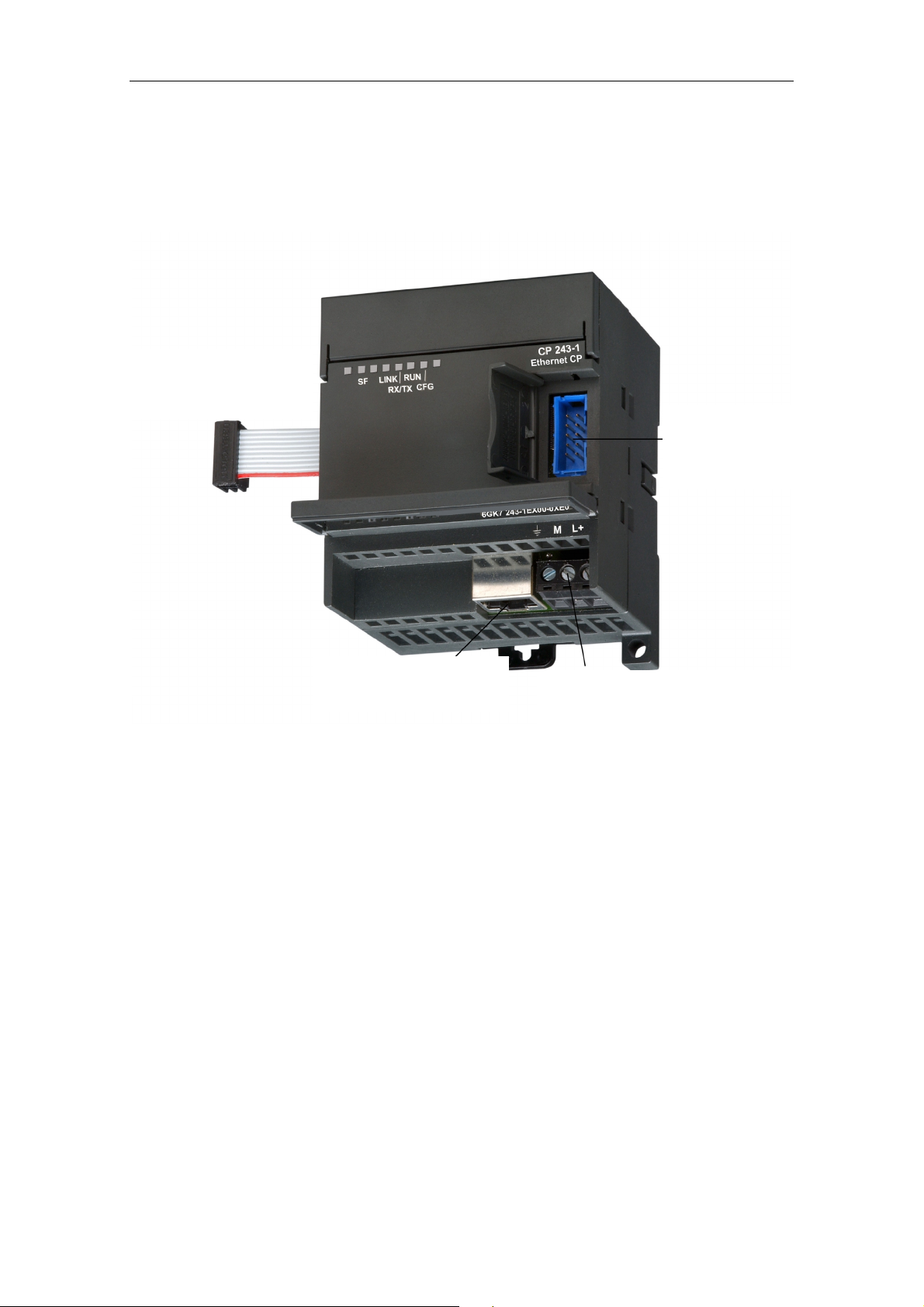
2.4 Connections
Front view:
Integrated ribbon cable
with socket for I/O bus
Connector
for I/O bus
8-pin RJ45 socket for
Ethernet connection
Fig. 2. Connections
The CP 243-1 has the following connections:
• Terminal block for 24 V DC supply voltage and ground connection
• 8-pin RJ45 socket for Ethernet connection
• Plug connector for I/O bus
• Integrated ribbon cable with socket for I/O bus
The connections are located underneath the covers of the front doors.
Terminal block for 24 V DC supply
voltage and ground connection
CP 243-1
J31069-D0428-U001-A1-7618
17
Page 22

Features and functions 09/02
2.5 Displays: Front LEDs
Fig. 3. Front with LED displays
Five LEDs are located on the front to indicate:
LED display Color Meaning
SF
LINK Green, continuous
RX/TX Green, flickering Ethernet activity:
Red, continuous
Red, flashes
System error:
Lights up when an error occurred
System error:
Flashes (approx. every second), if the configuration
is faulty and a BOOTP server cannot be found.
Connection via the RJ45 interface:
Ethernet connection has been established
Data are being received and transmitted via the
Ethernet
Note:
A packet received via the Ethernet is not necessarily
intended for the CP 243-1. The CP 243-1 initially
accepts every packet transmitted on the Ethernet.
Only then does it decide whether the package is intended for it.
The RX/TX LED also flashes as soon as the
CP 243-1 attempts to send a packet if the Ethernet
cable has been unplugged.
CP 243-1
18 J31069-D0428-U001-A1-7618
Page 23

09/02 Features and functions
LED display Color Meaning
RUN Green, continuous
CFG Yellow, continuous
Operational:
The CP 243-1 is ready for communication
Configuration:
Lights up when STEP 7 Micro/WIN 32 actively maintains a connection to the S7-200 CPU via the CP
243-1
Table 1: Functions of individual LED displays
While the CP243-1 is booting, the SF LED blinks twice. Then, the LINK LED and
the RX/TX LED blink several times. As soon as the RUN LED lights up, the
CP 243-1 has finished booting.
CP 243-1
J31069-D0428-U001-A1-7618
19
Page 24

Installation and commissioning 09/02
3 Installation and commissioning
Installation
The devices of the S7-200 series can be installed either in a control panel or on a
DIN rail. The modules can be arranged both horizontally and vertically. The
S7-200 CPU and the extension modules are designed to naturally dissipate heat
by means of convection. Therefore, leave a space of at least 25 mm both above
and below the device to ensure adequate heat dissipation. Long operating times at
maximum ambient temperature and maximum load shorten the operating life of the
electronic components.
Note
The position in an S7-200 system in which a CP 243-1 can be operated depends
on the firmware version of the S7-200 CPU.
When using firmware version 1.2 or higher, the CP 243-1 can be installed in any
position in an S7-200 system. For firmware versions below version 1.2, the
CP 243-1 must be installed directly next to the S7-200 CPU.
Wiring
!
Warning
If you attempt to install or remove the CP 243-1 or other devices with the
equipment switched on, you may receive an electric shock or the devices may
not operate properly.
If the power supply for the CP 243-1 and all connected devices is not switched
off while the devices are being installed or removed, this may result in personal
injury and/or damage to equipment.
Take all necessary safety precautions and ensure that the power supply for the
S7-200 and the CP 243-1 has been switched off before wiring the system.
CP 243-1
20 J31069-D0428-U001-A1-7618
Page 25

09/02 Installation and commissioning
General guidelines
General guidelines to follow when wiring your automation system:
• Ensure that all applicable and binding standards are complied with when wiring
the CP 243-1. Observe the appropriate national and regional regulations when
installing and operating the device. Inquire at local authorities regarding standards and regulations that must be complied with in your particular case.
• Wire the S7-200 CPU and the CP 243-1 in a de-energized state only!
• Use cables with a cross section appropriate for the current in each case. The
24 V supply of the CP 243-1 can be wired with cables with a cross section between 0.50 mm² and 1.50 mm². For wiring ground terminals, use cables with a
diameter of 1.50 mm².
• Do not tighten the connecting terminals excessively. The maximum permissible
torque is 0.56 Nm.
• Always lay the cables over as short a distance as possible. Cables should be
laid in pairs: a neutral conductor together with a phase conductor or signal cable.
• Separate AC wiring and high-voltage DC wiring with rapid switching sequences
from low-voltage signal wiring.
• Provide cables at risk of being struck by lightning with a suitable surge protec-
tion.
• The S7-200 CPU and the CP 243-1 should be connected to the same power
supply!
• The CP 243-1 is supplied with an integrated ribbon cable with a connector
socket for quick connection to other S7-200 components.
• The firmware version of the S7-200 CPU in use dictates in which slot a
CP 243-1 can be operated (see note on page 20).
• A maximum of one CP 243-1 can be used per CPU.
CP 243-1
J31069-D0428-U001-A1-7618
21
Page 26

Installation and commissioning 09/02
Electrical requirements
The input voltage must always be equal to 24 V DC.
Only apply 24 V DC voltage from power sources that are reliably electrically isolated from 120/230 V AC sources and similar sources of danger. Reliable electrical
isolation is defined, for example, in the following standards:
− PELV in accordance with EN60204-1
− Class 2 or circuit with limited voltage/current in accordance with UL 508
The supply voltage on the S7-200 backplane bus is supplied by the respective
S7-200 CPU.
Ensure that the CP 243-1 is properly grounded.
CP 243-1
22 J31069-D0428-U001-A1-7618
Page 27

09/02 Installation and commissioning
Space requirements for installation
Observe the following guidelines when installing your module:
• The CP 243-1 is designed to naturally dissipate heat by means of convection.
Therefore, leave a space of at least 25 mm both above and below the device to
ensure adequate heat dissipation. Long operating times at maximum ambient
temperature and maximum load shorten the operating life of the electronic
components.
• When installed horizontally, the CP 243-1 must always be installed immediately
to the right of the CPU.
• When installed vertically, the maximum allowable ambient temperature is lower
by 10 °C. The CP 243-1 must be arranged above the CPU. If you use a vertical
standard DIN rail, you should use the standard DIN rail stopper to prevent the
module from shifting.
• The depth required for installation is 75 mm.
Note
Erect the devices in such a manner that there is sufficient space for the wiring of
the inputs and outputs and for the communications cable connections.
25 mm
Distance required for
adequate heat
dissipation
25 mm
Fig. 4. Space requirements for installation
S7-200
Front view
CP 243-1
Front
cover
CP 243-1
75 mm
Side view
Installation
area
CP 243-1
J31069-D0428-U001-A1-7618
23
Page 28

Installation and commissioning 09/02
3.1 Dimensions for installation in a control panel
The CP 243-1 is provided with drill holes that facilitate installation in a control
panel.
96 mm
CPU
Minimum clearance of
9.5 mm between the
modules when installed in
control cabinet using
M4 bolts
Fig. 5. Dimensions for installation in a control panel
CP 243-1
63,2 mm
71,2 mm
3.2 Dimensions for installation on a DIN rail
The CP 243-1 can be installed on a DIN rail (DIN EN 50 022).
The following diagram shows the dimensions of a standard DIN rail:
1,0 mm
35 mm
88 mm
80 mm
7,5 mm
Fig. 6. Dimensions for installation on a DIN rail
CP 243-1
24 J31069-D0428-U001-A1-7618
Page 29

09/02 Installation and commissioning
3.3 Installation in a control panel
Procedure / steps
1. Provide the control panel with drill holes for bolts of size DIN M4. Adhere to the
notes and dimensions stated in Sections 3 and 3.1 for installation in a control
panel.
2. Screw the CP 243-1 into the control panel immediately to the right of the CPU
for horizontal installation and over the CPU for vertical installation. Use bolts of
size DIN M4.
3. Insert the ribbon cable of the CP 243-1 in the connector provided beneath the
front cover of the adjacent module or of the S7-200 CPU. The plug is shaped in
such a way that it cannot be incorrectly connected.
4. Connect the ground terminal:
Connect the ground terminal of the CP 243-1 to the next available ground to
achieve maximum interference immunity. Connecting all ground terminals separately is recommended. Use cables with a cross section of 1.5 mm
2
.
5. Connect the voltage supply.
6. Connect the Ethernet cable.
The transmission line is a 2 x 2-wire, shielded twisted-pair cable with a characteristic impedance of 100 Ohm. The transmission characteristics of this cable
must meet the specifications of Category 5 (Cat5 cable). The maximum length
of the connection between terminal device and network component (link segment) is limited to 100 m for the components defined in IEEE802.3.
Because the RJ45 connector in the CP 243-1 is also shielded, use of a shielded
Ethernet cable results in a continuous cable shield that ensures interferencefree Ethernet transmission. The RJ45 connector shield is connected to the
CP 243-1 ground terminal.
It is recommended that you ensure that the shield is well-grounded at both ends
of the transmission line. If, contrary to this recommendation, unshielded cables
are used or the shielding is not or improperly grounded at either end, it cannot
be guaranteed that the technical data with regard to electromagnetic radiation
and interference immunity will be met. In this event, responsibility for complying
with the maximum legal limits for electromagnetic radiation and interference
immunity (CE mark) lies with the operator of the system.
Installation of the device is now complete.
Note
The front doors of the CP 243-1 must be kept closed during operation.
The device must be installed in such a manner that the upper and lower air ducts
of the module are not obstructed and that air can circulate freely.
CP 243-1
J31069-D0428-U001-A1-7618
25
Page 30

Installation and commissioning 09/02
3.4 Installation on a standard DIN rail
Procedure / steps
1. Open the locking latch and mount the CP 243-1 on the DIN rail immediately to
the right of the CPU or over the CPU.
2. Close the locking latch to fasten the CP 243-1 onto the rail. Ensure that the
latch engages properly and that the device is securely fastened to the rail.
Note
In environments subject to strong vibrations, or for vertical installation, it may be
necessary to prevent the devices from shifting on the DIN rail by using standard
DIN rail stoppers.
3. Insert the ribbon cable of the CP 243-1 into the connector provided beneath the
front cover of the adjacent module or the S7-200 CPU. The plug is shaped in
such a way that it cannot be incorrectly connected.
4. Connect the ground terminal:
Connect the ground terminal of the CP 243-1 to the next available ground to
achieve maximum interference immunity. Connect all ground terminals separately is recommended. Use cables with a cross section of 1.5 mm
2
.
5. Connect the voltage supply.
6. Connect the Ethernet cable.
The transmission line is a 2 x 2-wire, shielded twisted-pair cable with a characteristic impedance of 100 Ohm. The transmission characteristics of this cable
must meet the specifications of Category 5 (Cat5 cable). The maximum length
of the connection between terminal device and network component (link segment) is limited to 100 m for the components defined in IEEE802.3.
Because the RJ45 connector in the CP 243-1 is also shielded, use of a shielded
Ethernet cable results in a continuous cable shield that ensures interferencefree Ethernet transmission. The RJ45 connector shield is connected to the
CP 243-1 ground terminal.
It is recommended that you ensure that the shield is well-grounded at both ends
of the transmission line. If, contrary to this recommendation, unshielded cables
are used or the shielding is not or improperly grounded at either end, it cannot
be guaranteed that the technical data with regard to electromagnetic radiation
and interference immunity will be met. In this event, responsibility for complying
with the maximum legal limits for electromagnetic radiation and interference
immunity (CE mark) lies with the operator of the system.
Installation of the device is now complete.
CP 243-1
26 J31069-D0428-U001-A1-7618
Page 31

09/02 Installation and commissioning
Note
The front doors of the CP 243-1 must be kept closed during operation.
The device must be installed in such a manner that the upper and lower air ducts
of the module are not obstructed and that air can circulate freely.
3.5 Replacement of the CP 243-1
If the CP 243-1 (6GK7 243-1EX00-0XE0) has to be replaced, reprogramming is not
required since the configuration data and the user program are stored in the
S7-200 CPU as non-volatile data.
3.6 Removing the CP 243-1
!
!
Warning
If you attempt to install or remove the CP 243-1 or other devices with the equipment switched on, you may receive an electric shock or the devices may not operate properly.
If the power supply for the CP 243-1 and all connected devices is not switched off
while the devices are being installed or removed, this may result in personal injury
and/or damage to equipment.
Take all necessary safety precautions and ensure the power supply for the S7-200
and the CP 243-1 has been switched off before installing or removing the system.
Proceed as following to remove the CP 243-1 or any other extension module of the
S7-200:
1. Switch off the voltage supply to the S7-200 CPU, the CP 243-1 and all extension modules.
2. Detach all cables and lines from the device that you wish to remove.
3. Open the front cover and detach the ribbon cable from the adjacent modules.
4. Unscrew the screws or open the locking latch and remove the module from the
control panel or DIN rail.
Warning
Installing the wrong device can lead to unexpected results when operating the
S7-200.
Replacing the CP 243-1 by another version or not aligning the device properly can
lead to personal injury and/or damage to the equipment.
Therefore, always replace the CP 243-1 by the same version and align it properly.
CP 243-1
J31069-D0428-U001-A1-7618
27
Page 32

Configuration 09/02
4 Configuration
4.1 Configuration options
An S7-200 system can communicate with another S7-200 system and with an
S7-300, S7-400 or OPC-based system via the CP 243-1A.
There are two methods of configuring a communication of this type in an S7-200
system:
• Configuration using STEP 7 Micro/WIN 32, version 3.2.1 or higher
• Configuration using an S7-200 user program
Attention
The system can only be configured via an S7-200 user program if the CRC
mechanism has been switched off.
Since the configuration data can no longer be fully checked for consistency with
regard to intended and unintended changes after the CRC check of the CP 243-1
has been switched off, there can be no guarantee in this case that the CP or the
components connected in the network will operate correctly.
In both cases, the configuration data are stored in the data block of the S7-200
CPU. Every time the CP 243-1 is restarted, the data are read once from that location.
Attention
To protect the configuration data of the CP 243-1 if the system goes into a novoltage state, these data must be stored in a non-volatile data storage area of the
S7-200 CPU.
In a standard S7-200 system, the entire data block is defined as non-volatile. However, this default setting on your S7-200 system could have been modified if
changes were made to the configuration.
If STEP 7 Micro/WIN 32 is used for reconfiguring or modifying the configuration of
the CP 243-1, the new configuration becomes effective only after the CP 243-1 is
restarted. If the S7-200 CPU changes from STOP to RUN mode after such a reconfiguration, the CP 243-1 is automatically restarted. However, if the CP 243-1 is
configured directly in the S7-200 user program, the configuration can be enabled
by calling up the "ETHx_CFG" subroutine in the user program. Calling up the subroutine also causes the CP 243-1 to restart.
The TCP/IP address parameter (IP address, subnet mask, IP address of a Gateway) can either be defined during configuration or the CP 243-1 can be configured
in such a way that it dynamically retrieves the TCP/IP address parameters from a
BOOTP server while booting.
CP 243-1
28 J31069-D0428-U001-A1-7618
Page 33

09/02 Configuration
If an S7-200 system is to communicate with an S7-300, S7-400 or OPC-based system via a CP 243-1, configure such an S7-300, S7-400 or OPC-based system using STEP 7, version 5.1 or higher, with Service Pack 3 or higher (with NCM S7 for
Industrial Ethernet).
Note
The CP 243-1 may independently switch to another Gateway after booting due to
special network-based services ("ICMPRedirect"). After approx. 30 seconds, the
CP 243-1 switches back to the Gateway originally configured. Thus, the Gateway
actually used by CP 243-1 can temporarily deviate from the one defined in the configuration.
You can read out the Gateway the CP 243-1 is using at any particular time from
the storage area of the S7-200 CPU in which the NPB data block is stored (see
Chapter 4.4.3). To do so, use the CP 243-1 diagnostics window in STEP 7 Micro/WIN 32 or make use of a user program.
CP 243-1
J31069-D0428-U001-A1-7618
29
Page 34

Configuration 09/02
4.2 Value ranges of the configuration data
4.2.1 IP address
The IP addresses to be specified at various points within the configuration must
comply with the general conventions defining IP address validity.
According to these conventions, certain IP addresses serve specific purposes.
These addresses will not be accepted by the CP 243-1. They include:
• Loopback: 127.0.0.0 - 127.255.255.255
• "Class D" addresses: 224.0.0.0 - 239.255.255.255
• "Class E" addresses: 240.0.0.0 - 247.255.255.255
• Broadcast addresses: e.g. 255.255.255.255
4.2.2 Subnet mask
If a subnet mask is specified during configuration, its structure must comply with
the general conventions defining subnet mask validity.
Please note that the validity of an IP address and an associated subnet mask are
interdependent.
4.2.3 TSAPs
The TSAPs consist of 2 bytes. The first byte specifies the connection and the second byte is composed of the rack number and the slot of the communications
module. The following value ranges apply for the first byte.
• Local TSAP value range: 16#02, 16#10 - 16#FE
• Remote TSAP value range: 16#02, 16#03, 16#10 - 16#FE
The structure of the second byte is not checked by the CP 243-1.
CP 243-1
30 J31069-D0428-U001-A1-7618
Page 35

09/02 Configuration
4.3 Configuring a CP 243-1 using STEP 7 Micro/WIN 32
After you have installed and started STEP 7 Micro/WIN 32 on your PC, start the
Wizard for the CP 243-1. It is located in the “Extras“ menu under the "Ethernet
Wizard..." item. It is also found on the left side of the window in STEP 7 Micro/WIN 32 in the window with the navigation bar under the "E
the appropriate view is enabled in your STEP 7 Micro/WIN 32.
The Ethernet Wizard supports you when configuring your CP 243-1. You can enter
all relevant parameters in several masks. User guidance is designed such that you
cannot enter a new mask until all entries in the present mask are complete and
correct. Otherwise, an error message appears.
The individual configuration steps through which the Wizard guides you are briefly
described below.
Note
Detailed information is available in the STEP 7 Micro/WIN 32 documentation that is
supplied together with the STEP 7 Micro/WIN 32.
xtras" item, provided
After you have started the Wizard, an entry mask containing general information
appears. After you have read the contents, click on “Continue>” to proceed.
Defining the position of the CP 243-1 in the S7-200 system
Using the second mask, define the position of the CP 243-1 in the S7-200 system.
This position can be manually entered, or the Wizard can search for a CP 243-1 in
your S7-200 system. If it locates a CP 243-1, its position is automatically displayed
in the S7-200 system. Otherwise, an error message appears.
Defining the TCP/IP address parameters and transmission type
The next mask is used to define the TCP/IP address parameters and the transmission type to be used.
There are two methods for setting the TCP/IP address parameters:
1. Enter the parameters in the appropriate entry window manually.
2. Activate the access to a BOOTP server. In this case, the CP 243-1 retrieves the
TCP/IP address parameters from a BOOTP server as it boots. If the CP 243-1
cannot locate a BOOTP server in your TCP/IP network, it goes into Reset
mode, restarts and again attempts to establish contact with a BOOTP server. It
continues doing so until it locates a BOOTP server from which it can retrieve
TCP/IP address parameters.
CP 243-1
J31069-D0428-U001-A1-7618
31
Page 36

Configuration 09/02
Defining the address of the control byte and the number of connections
Use the next mask to specify the address of the byte in the memory address space
of your S7-200 system from which the CP 243-1 can be addressed from the
S7-200 CPU. This address depends on the position of the CP 243-1 in your
S7-200 system and on the number of outputs in your S7-200 system. If, when you
began configuring the system, you had the Ethernet Wizard determine the position
of the CP 243-1 in your S7-200 system, the Wizard will now provide you with the
address to be used.
Basically, you can determine the memory address spaces occupied by the modules present in your S7-200 system by enabling the "Information..." entry in the
"Target system" menu in STEP 7 Micro/WIN 32. In this manner you will also find
the address under which your CP 243-1 can be addressed in your S7-200 system.
In this mask, you can also define the maximum number of connections your
CP 243-1 should maintain in parallel at any one time. Up to 8 such connections
can be maintained. A mask in which you can configure the connection then appears for each connection you specify here.
Configuring the individual connections
The connections that you established in the previous mask are configured in the
masks that follow. For each connection, you must first define whether your S7-200
system should be operated as a client or server. This will determine the structure of
the mask.
If your S7-200 system is to be operated on the connection as a client, then you
must specify the address of the communication partner and the communications
end point ("TSAP") in this partner. Moreover, in an additional mask, you must specify which data are to be exchanged between your S7-200 system and the specified
communication partner. At this point you also define whether these data are to be
read or written. Up to 32 read/write commands can be defined per connection.
If your S7-200 system is operated on the connection as a server, then you can define to which communication partner you wish to grant access to your system by
assigning an IP address. However, you can also set each server so that it always
grants access from any IP address. You must also define the communications end
point ("TSAP") in your communication partner from which you grant access to your
S7-200 system.
A Keep Alive system can be enabled for both client and server connections.
Please use the communications end points ("TSAPs") of your communication partner specified in the configuration of that partner. In an S7-200 system, it is generated using STEP 7 Micro/WIN 32. In an S7-300, S7-400 or OPC-based system,
use STEP 7 to do so (see also Chapter 4.4).
CP 243-1
32 J31069-D0428-U001-A1-7618
Page 37

09/02 Configuration
Note
The specifications for the communications end points ("TSAPs") in STEP 7 and in
STEP 7 Micro/WIN 32 must be mutually compatible.
CP 243-1
J31069-D0428-U001-A1-7618
33
Page 38

Configuration 09/02
Enabling / disabling the CRC mechanism and defining the Keep Alive time
Once you have configured the connections, you must specify in the next mask
whether or not your configuration data on the S7-200 CPU are to be protected by a
CRC mechanism against being unintentionally overwritten.
If the CRC mechanism is enabled, the CP 243-1 checks, while it is booting,
whether its configuration data, which it reads out of the memory of the S7-200
CPU, were overwritten by the user program. If so, it stops booting and attempts to
retrieve its TCP/IP address parameters from a BOOTP server. If successful, it continues booting. In this case, however, only the MicroWN channel is enabled. Thus,
the CP 243-1 can then only communicate with STEP 7 Micro/WIN 32 but not with
other controllers.
Activating the CRC mechanism is recommended. This is the only way that the
CP 243-1 can recognize unintended changes to the configuration data by the user
program.
If the CRC mechanism is not enabled, you can change the configuration data of
the CP 243-1 in the user program. However, the CP 243-1 will not be able to recognize if the data have been unintentionally overwritten.
Attention
An S7-200 user program can only be used to configure data if the CRC mechanism
has been switched off.
The CP 243-1 cannot completely check the configuration data for consistency with
regard to intentional and unintentional changes after the CRC check has been
switched off. Therefore, in this case there is no guarantee whatsoever that the CP
or the components connected in the network will function correctly.
In the same mask, you can set the Keep Alive time for all configured connections
at once. If a connection partner should suddenly be unavailable, e.g. if there is a
fault in the TCP/TP network or an error with the communication partner, then the
value entered here is to used to determine the time after which the CP 243-1 will
recognize the problem.
You already defined which connections are to be monitored by this time period
when you configured the individual connections.
CP 243-1
34 J31069-D0428-U001-A1-7618
Page 39

09/02 Configuration
Defining the memory area for storing the configuration
Finally, use the next mask to define the memory area in which your configuration
data are to be stored on the S7-200 CPU. The Wizard will assist you in doing so.
The Wizard then informs you about which subroutines it is establishing on the basis of your configuration and where your configuration data are being stored.
Configuration of the system is now complete.
Attention
Ensure that the memory area in which the Ethernet Wizard stores the configuration
data are not used by your S7-200 user program.
CP 243-1
J31069-D0428-U001-A1-7618
35
Page 40

Configuration 09/02
4.4 Configuring a CP 243-1 from a user program
The configuration data of the CP 243-1 are stored in the S7-200 CPU memory and
can therefore be changed directly from an S7-200 user program. The cyclic redundancy check (CRC) must be disabled for the configuration data so that the
CP 243-1 will accept configuration data which were changed in this way during the
next startup. For this purpose, the value 16#AC must be entered for Byte 13 of the
CDB data structure. This takes place automatically as soon as the CRC mechanism is switched off in the Ethernet Wizard.
Attention
Configuring the CP 243-1 from a user program is only recommended for experienced programmers.
The CP 243-1 cannot completely check the configuration data for consistency with
regard to intentional and unintentional changes after the CRC check has been
switched off. Therefore, in this case there is no guarantee whatsoever that the CP
or the components connected in the network will function correctly.
Note
Data of the “WORD“ (2 bytes) or "DWORD“ (4 bytes) type are stored in an S7-200
in "big endian“ format, i.e.
Address n: MSB
Address n+1: LSB (analogous for DWORD).
CP 243-1
36 J31069-D0428-U001-A1-7618
Page 41

09/02 Configuration
4.4.1 Occupied system flag area (SM area)
The CP 243-1 occupies 50 bytes in the S7-200 CPU system flag area. The address of these 50 bytes depends on the position in which a CP 243-1 is currently
located in an S7-200 system. Primarily general information and status information
of the CP 243-1 are stored in these 50 bytes. The last four bytes contain a pointer
through which one can access the CP 243-1 configuration data. These configuration data are consecutively stored in the S7-200 CPU variables memory. They are
subdivided into the:
• Configuration Data Block (CDB)
• Network Parameter Block (NPB)
• Network Data Block (NDB)
The following table shows the relationship between the position of a module in the
S7-200 system and the associated system flag area.
Position in S7-200
system
CPU - -
0 200..249 -
1 250..299 Only supported by CPU firmware version
2 300..349 Only supported by CPU firmware version
3 350..399 Only supported by CPU firmware version
4 400..449 Only supported by CPU firmware version
5 450..499 Only supported by CPU firmware version
6 500..549 Only supported by CPU firmware version
Occupied SM
area
Remark
1.2 or higher
1.2 or higher
1.2 or higher
1.2 or higher
1.2 or higher
1.2 or higher
Table 2: System flag area
CP 243-1
J31069-D0428-U001-A1-7618
37
Page 42

Configuration 09/02
4.4.2 Structure of the Configuration Data Blocks (CDB)
The CDB is generated by the Ethernet Wizard in STEP 7 Micro/WIN 32. The following table shows the structure of the CDB.
Byte offset in
variables mem-
ory
Header
0-4 Module name 5 bytes ASCII 16#4350323433
5-6 Length of CDB 2 bytes hex 16#006C
7-8 Length of NPB 2 bytes hex 16#0014
General information
9 Internal use 1 byte hex
10 Internal use 1 byte hex
11-12 Reserved for STEP 7 Micro/WIN 2 bytes hex ---
13-14 Common Flag
Bit [0] Duplex Mode
0: Half Duplex
1: Full Duplex
Bit [1] Data Rate
0: 10 Mbit/s
1: 100 Mbit/s
Bit [2] Auto Negotiation
0: No auto negotiation
1: Auto negotiation
Bit [3] BOOTP
0: Use configured network pa-
rameters
1: BOOTP
Bit [4-7] Not in use
Bit [8-15] CRC validation
16#00 CRC check enabled
16#AC CRC check disabled
15-18 Configured IP address
This field should be set to
16#00000000 if BOOTP is used.
19-22 Configured subnet mask
This field should be
Description Data format Example
“CP243”
(108 decimal)
(20 decimal)
2 bytes hex 16#0004:
Auto negotiation,
use configured network parameters,
CRC check enabled
16#AC04:
Auto negotiation,
use configured network parameters,
CRC check disabled
4 bytes hex 192.12.45.23:
16#C00C2D17
4 bytes hex 255.255.255.0:
16#FFFFFF00
CP 243-1
38 J31069-D0428-U001-A1-7618
Page 43

09/02 Configuration
Byte offset in
variables mem-
ory
set to 16#00000000 if BOOTP is
used.
23-26 IP address of Gateway.
16#00000000 means: do not use
Gateway.
This field should be set to
16#00000000 if BOOTP is used.
27-28 Time parameter for Keep Alive in
seconds
S7 connection 0 section (If not all bytes are used in this section, they should be filled in with
16#00)
29 Flag byte
Bit [0] Server/Client
0: Server
1: Client
Bit [1] Keep Alive
0: No Keep Alive support
1: Keep Alive support
Bit [2-6] Not in use
Bit [7] Section valid
0: Section not in use
1: Section in use
30-33 For server functionality:
IP address space of client for access
protection
16#00000000: No protection
16#XXXXXX00 Client of the same
Class-C segment is permissible
16#XXXXXXXX only exactly the
same address is allowable
For client functionality:
IP address of S7 server
34-35 Local TSAP 2 bytes hex 16#1000
S7 connection 1 section (If not all bytes are used in this section, they should be filled in with
16#00)
38 Flag byte
See S7 connection 0 section.
39-42 IP address of partner
See S7 connection 0 section.
43-44 Local TSAP 2 bytes hex 16#1100
Description Data format Example
4 bytes hex 192.12.45.24:
16#C00C2D18
2 bytes hex
1 byte hex 16#82:
4 bytes hex 192.12.45.22:
1 byte hex See S7 connection 0
4 bytes hex See S7 connection 0
16#001E:
30 seconds
Server, Keep Alive
support, the S7 connection, 0, is in use
and contains valid
data.
16#C00C2D16.
section.
section.
CP 243-1
J31069-D0428-U001-A1-7618
39
Page 44

Configuration 09/02
Byte offset in
variables mem-
ory
45-46 Remote TSAP 2 bytes hex See S7 connection 0
S7 connection 2 section (If not all bytes are used in this section, they should be filled in with
16#00)
47 Flag byte
See S7 connection 0 section.
48-49 IP address of partner
See S7 connection 0 section.
52-53 Local TSAP 2 bytes hex 16#1200
54-55 Remote TSAP 2 bytes hex See S7 connection 0
S7 connection 3 section (If not all bytes are used in this section, they should be filled in with
16#00)
56 Flag byte
See S7 connection 0 section.
57-60 IP address of partner
See S7 connection 0 section.
61-62 Local TSAP 2 bytes hex 16#1300
63-64 Remote TSAP 2 bytes hex See S7 connection 0
S7 connection 4 section (If not all bytes are used in this section, they should be filled in with
16#00)
65 Flag byte
See S7 connection 0 section.
66-69 IP address of partner
See S7 connection 0 section.
70-71 Local TSAP 2 bytes hex 16#1400
72-73 Remote TSAP 2 bytes hex See S7 connection 0
S7 connection 5 section (If not all bytes are used in this section, they should be filled in with
16#00)
74 Flag byte
See S7 connection 0 section.
75-78 IP address of partner
See S7 connection 0 section.
79-80 Local TSAP 2 bytes hex 16#1500
81-82 Remote TSAP 2 bytes hex See S7 connection 0
Description Data format Example
section.
1 byte hex See S7 connection 0
section.
4 bytes hex See S7 connection 0
section.
section.
1 byte hex See S7 connection 0
section.
4 bytes hex See S7 connection 0
section.
section.
1 byte hex See S7 connection 0
section.
4 bytes hex See S7 connection 0
section.
section.
1 byte hex See S7 connection 0
section.
4 bytes hex See S7 connection 0
section.
section.
CP 243-1
40 J31069-D0428-U001-A1-7618
Page 45

09/02 Configuration
Byte offset in
variables mem-
ory
S7 connection 6 section (If not all bytes are used in this section, they should be filled in with
16#00)
83 Flag byte
See S7 connection 0 section.
84-87 IP address of partner
See S7 connection 0 section.
88-89 Local TSAP 2 bytes hex 16#1600
90-91 Remote TSAP 2 bytes hex See S7 connection 0
S7 connection 7 section (If not all bytes are used in this section, they should be filled in with
16#00)
92 Flag byte
See S7 connection 0 section.
93-96 IP address of partner
See S7 connection 0 section.
97-98 Local TSAP 2 bytes hex 16#1700
99-100 Remote TSAP 2 bytes hex See S7 connection 0
STEP 7 Micro/Win Server section
101 Flag byte
Bit [0] Server
0: Server
1: Not supported
Bit [1] Keep Alive
0: No Keep Alive support
1: Keep Alive support
Bit [2-6] Not in use
Bit [7] Section valid
0: Not supported
1: Section in use
102-105 Internal use 4 bytes hex
CRC section
106-107 CRC over all CDB bytes without the
CRC section itself
Description Data format Example
1 byte hex See S7 connection 0
section.
4 bytes hex See S7 connection 0
section.
section.
1 byte hex See S7 connection 0
section.
4 bytes hex See S7 connection 0
section.
section.
1 byte hex 16#82:
Server, Keep Alive
support,
the STEP 7 Micro/WIN
Server section is in
use and contains valid
data.
2 bytes hex
Table 3: CDB structure
CP 243-1
J31069-D0428-U001-A1-7618
41
Page 46

Configuration 09/02
4.4.3 Structure of the Network Parameter Blocks (NPB)
This data block is generated by the CP 243-1 itself in accordance with the current
set of network parameters. It contains the TCP/IP parameter values currently in
use, provided the CP 243-1 has been correctly configured. In the event of a configuration error, the NPB will not contain any valid data.
Byte offset in
variables mem-
ory
108-109 Common flag byte
Bit [0] Duplex Mode
0: Half Duplex
1: Full Duplex
Bit [1] Data Rate
0: 10 Mbit/s
1: 100 Mbit/s
Bit [2] Auto Negotiation
0: No auto negotiation
1: Auto negotiation
Bit [3] BOOTP
0: Use configured net-
1: BOOTP
Bit [4-15] Not in use
110-113 Current IP address Dependent on cur-
114-117 Current subnet mask Dependent on cur-
118-121 IP address of current Gate-
ways
122-127 MAC address Read out from
Description Calculation of the
value
Dependent on current configuration
work parameters
rent configuration
rent configuration
Dependent on current configuration
hardware
Data format Example
2 Byte Hex 16#04: Auto nego-
tiation,
use configured
network parameters
4 bytes hex 192.12.45.23:
16#C00C2D17
4 bytes hex 255.255.255.0:
16#FFFFFF00
4 bytes hex 192.12.45.24:
16#C00C2D18
6 bytes hex 16#080006021F04
08-00-06-02-1F-04
Table 4: NPB structure
CP 243-1
42 J31069-D0428-U001-A1-7618
Page 47

09/02 Configuration
4.4.4 Structure of the Network Data Blocks (NDB)
The NDB is generated by the Ethernet Wizard in STEP 7 Micro/WIN 32. The
read/write commands possible for clients are configured in this data bock. Up to 32
read/write commands can be configured for each of the 8 possible communication
channels. If the CP 243-1 is operated on a channel as a server, then there is no
entry in the NDB structure for this channel.
The following table shows the structure of the NDB. The codes for read/write commands are represented by the letters n, m, p = 0, ..., 31, and the channel codes are
represented by the letter r = 0, ...,7.
Byte offset in
variables memory
Header
128-129 NDB_LENGTH Specifies the length of the NDB 2 bytes hex
Entries for first client channel
130 COM_CH0_ID Code of first client channel 1 byte hex
131 COM_CH0_OFF Specifies the offset to the first communication
132 COM_CH0_LEN0 Specifies the length of the first communica-
... n bytes
n+132 COM_CH0_LENn Specifies the length of the COMn structure 1 byte hex
n+5 COM_CH0_0 COM0 structure for read/write command 0 for
... ... ... ASCII
+
5
n
−
1
n
+
∑
=
0
i
_0_
COM_CH0_n COMn structure for read/write command n for
LENiCHCOM
Entries for second client channel
... COM_CH1_ID Code of second client channel 1 byte hex
... COM_CH1_OFF 1 byte hex
... COM_CH1_LEN0 1 byte hex
... ... 1 byte hex
... COM_CH1_LENm 1 byte hex
... COM_CH1_0 ASCII
... ... ASCII
... COM_CH1_m ASCII
Name Description Data
format
1 byte hex
block (COM0)
1 byte hex
tion blocks (COM0)
ASCII
first client channel:
"<op>=<cnt>,<local_buffer>,<remote_buffer>"
(For description, see Table 6)
ASCII
first client channel:
"<op>=<cnt>,<local_buffer>,<remote_buffer>"
(For description, see Table 6)
... ... (up to 8 channels)
Entries for n-th client channel
... COM_CHr_ID Code of last client channel 1 byte hex
CP 243-1
J31069-D0428-U001-A1-7618
43
Page 48

Configuration 09/02
Byte offset in
variables memory
... COM_CHr_OFF 1 byte hex
... COM_CHr_LEN0 1 byte hex
... ... 1 byte hex
... COM_CHr_LENp 1 byte hex
... COM_CHr_0 ASCII
... ... ASCII
... COM_CHr_p ASCII
CRC section
The last two bytes
of the NDB
CRC over all NDB
bytes without the
CRC section itself
Name Description Data
format
2 bytes hex The last two
bytes of the
NDB
Table 5: NDB structure
Name Description Data
format
<op>
<cnt>
<local_buffer> Address of memory area in local system
<remote_buffer> Address of memory area in communication partner
Command type
Value range: “R“ for a “read“,
“W“ for a “write“
Number of bytes to be transmitted
Value range: "1“ to “212“
Value range:
“VB0“ to “VBx“, where x is the max. V address
Value range:
“IB0“ to “IBx“, where x is the max. input address
(S7-200 / S7-300 / S7-400)
“QB0“ to “QBx“, where x is the max. output address
(S7-200 / S7-300 / S7-400)
“MB0“ to “MBx", where x is the max. flag address
(S7-200 / S7-300 / S7-400)
“VB0“ to “VBx“, where x is the max. variables address
(S7-200)
“DB0.DBB0“ to “DBx.DBBy“, where x is the max. DB
number,
y is the highest address in the corresponding data block
within the DB (S7-300 / S7-400)
ASCII
ASCII
ASCII
ASCII
Table 6: Configuration of read/write commands
CP 243-1
44 J31069-D0428-U001-A1-7618
Page 49

09/02 Configuration
4.5 Configuring a communication partner with STEP 7
Using the S7-300 system as an example, the following section outlines the steps
you need to take in STEP 7 to configure the system for communication with an
S7-200 system via the associated Ethernet communications processor. The procedure for the S7-400 system is similar.
For the exact configuration steps, please refer to the STEP 7 description (MLFB:
6ES7 810-4CC05-0YX0) or the handbooks for the CP 343-1 and the CP 443-1.
In S7-300 and S7-400 systems, a distinction is made between configured and free
connections. For configured connections, the connection parameters are specified
by the user. In contrast, free connections do not have to be configured in STEP 7.
CP 243-1
J31069-D0428-U001-A1-7618
45
Page 50

Configuration 09/02
Configured connections
If you would like to work with a configured connection, you must first insert a new
S7 connection in the STEP 7 NetPro program package. In the "Insert new connection" mask, specify the type of station with which you would like to establish a connection. For the connection partner, select the "(unspecified)" type.
These connections must now be configured. To do so, you must first define in the
"Properties - S7 connection" mask (see Figure 7) whether your S7-300 or S7-400
system is to act as an active or passive participant. If your S7-300 or S7-400 system is to communicate with an S7-200 system, also define whether your system is
to be operated as a client or server. If you would like to operate your S7-300 or S7400 system as a client, enable the "Active connection generation" entry. Your system will be operated as a server if the entry is not enabled. Then make the settings
necessary to process your S7 connection with the TCP/IP protocol. To do so, select the "TCP/IP" item. To establish the TCP/IP connection with your partner, also
specify the partner’s IP address.
Fig. 7. "Properties – S7 connection" mask
CP 243-1
46 J31069-D0428-U001-A1-7618
Page 51

09/02 Configuration
Finally, in the "Address details" mask, define the communication end points
("TSAPs") to be used. The TSAP of a connection in the S7-200 system is found in
the STEP 7 Micro/WIN 32 in the mask in which you configured the individual connections, under the "Local properties" entry. Enter the communication end point
specified there in the fields provided for the partner’s TSAP in the "Address details"
mask. The communication end point assigned for the connection in your S7-300 or
S7-400 system is found in the same mask under the "Local" entry in the "TSAP"
field. Enter the value specified there in STEP 7 Micro/WIN 32 in the mask from
which you retrieved the communication end point used there. The value needs to
be entered in the "Remote properties" entry in the "TSAP" field in that mask.
S7-300 system as client
If you would like to operate an S7-300 system as a client, i.e. if you have enabled
the "Active connection generation" item in the "Properties - S7 connection" mask,
then you cannot directly use the TSAP specified in STEP 7 in the "Local" entry in
STEP 7 Micro/WIN 32 as a connection end point for your S7-300 system. You
must first transform this TSAP according to the following rules:
1st byte of TSAP:
Taken over from STEP 7, "Address details" mask, "Local" entry, "TSAP" field.
Example:
2nd byte of TSAP:
Derived from the rack and slot of your Ethernet communications processor in your
S7-300 system.
The number of the rack in which your Ethernet communications processor is inserted in your S7-300 system is specified in the first 3 bits.
The remaining 5 bits contain the slot of your Ethernet communications processor in
your S7-300 system.
These two values are found in the STEP 7 HWConfig program package.
A CP 343-1 is inserted in your S7-300 system in slot 4 in rack 0. When you configure a connection with STEP 7, a value of 10.02 is displayed as the local TSAP. In
STEP 7 Micro/WIN 32, you must use a TSAP of 10.04 for the communication end
point in the S7-300 system (1st byte (here: 10) is taken over, 2nd byte is derived
from the rack (here 0) and the slot (here 4)).
Attention
The definitions for the communication end points ("TSAPs") in STEP7 and in
STEP 7 Micro/WIN 32 must be mutually compatible.
CP 243-1
J31069-D0428-U001-A1-7618
47
Page 52

Configuration 09/02
Free connections
A free connection can only be used if your S7-300 or S7-400 system is to be operated as a server. Free connections do not have to configured in STEP 7. Standard
S7-300 and S7-400 systems are set up to communicate via free connections.
If you would like to make use of the mechanism for free connections in your S7300 or S7-400 system, the client side for each of these connections must still be
configured. In STEP 7 Micro/WIN 32, there is not difference between use of these
connections and communicating via connections that were configured in the S7300 or S7-400 system. For free connections, you must merely ensure that the first
byte of the TSAP over which these connections pass to the S7-300 and S7-400
systems is always assigned a value of 0x03. The second byte of the TSAP is derived, as described above, from the rack and slot number of the CPU used in your
S7-300 or S7-400 system.
Note
S7-200 systems do not support free connections. This means that you must configure each connection in an S7-200 system, regardless of whether your system is
to be operated as a client or server.
CP 243-1
48 J31069-D0428-U001-A1-7618
Page 53

09/02 Configuration
4.6 Behavior of CP 243-1 in the event of configuration errors
If the CP 243-1 recognizes an invalid configuration, it attempts to retrieve its
TCP/IP address parameters (IP address, subnet mask, IP address of Gateway) via
a BOOTP service. The CP 243-1 continues the attempt for approx. 1 minute. If it
does not receive a response from a BOOTP service within this time or if the response is invalid or faulty, the red LED (“SF“) flashes for approx. 30 seconds. This
procedure is cycled through until the CP 243-1 either finds a valid configuration in
the S7-200 CPU memory or receives a valid response from a BOOTP server.
If the CP 243-1 receives a valid BOOTP response, it configures itself as follows:
• IP address, subnet mask and IP address of the Gateway are taken over from
the BOOTP response
• The transmission type is set to "Auto Negotiation".
• The Keep Alive time for connections is set to 30 seconds.
When configured in this way, the CP 243-1 is able to access the S7-200 CPU from
STEP 7 Micro/WIN 32 through Ethernet. A new valid configuration can now be
loaded in this way. Communication with other controllers is not possible under
these conditions. After a reset, the CP 243-1 configures itself in accordance with
the new configuration.
Note
The Auto Negotiation mode only operates if all connected network components
support this mode.
CP 243-1
J31069-D0428-U001-A1-7618
49
Page 54

Programming 09/02
5 Programming
Use STEP 7 Micro/WIN 32 to develop S7-200 user programs. For you to be able to
use the CP 243-1 functions in these programs, the STEP 7 Micro/WIN 32 you use
must be version V3.2.1 or higher.
To be able to operate the CP 243-1 as a client or as a server, at least one of the
communications channels of the CP 243-1 must be configured accordingly. In addition, the S7-200 user program must also be programmed accordingly.
The CP 243-1 is programmed in the S7-200 user program in the following subroutines, where the position in which a CP 243-1 is located in the S7-200 system is included in the name of the subroutine:
• ETHx_CTRL (x stands for the slot position, possible values: 0.1, ...6)
• ETHx_CFG (x stands for the slot position, possible values: 0.1, ...6)
• ETHx_XFR (x stands for the slot position, possible values: 0.1, ...6)
These subroutines are generated by the Ethernet Wizard integrated in STEP 7 Micro/WIN 32 when configuration is completed. You will then find these subroutines
in STEP 7 Micro/WIN 32 in the window in the operation tree under the "Subprogram calls" entry. Which subroutines are generated by the Wizard when configuration is completed depends on the data that you specified during configuration.
Attention
These subroutines may not be called up in the S7-200 user program by interrupt
routines.
CP 243-1
50 J31069-D0428-U001-A1-7618
Page 55

09/02 Programming
5.1 ETHx_CTRL
The ETHx_CTRL subroutine is used to initialize and monitor the CP 243-1. You
must call up this subroutine in your S7-200 user program at the start of each cycle
if you wish to access the functions of a CP 243-1. Calling up the subroutine causes
the CP 243-1 to restart when the CRC check is switched on, provided the
CP 243-1 has recognized a change in the configuration data. In contrast, if the
CRC check is switched off, the CP 243-1 is always restarted after a user program
or a new configuration is downloaded into the S7-200 CPU from STEP 7 Micro/WIN 32 and the S7-200 CPU is subsequently started.
The return values provide information on the general state of the CP 243-1 and the
state of the up to eight possible communication channels. If an error occurred in
the CP 243-1, you can read out the associated error code from the Error return parameter. The ETHx_CTRL subroutine is always generated by the Ethernet Wizard
in STEP 7 Micro/WIN 32 as soon as you have finished configuring the CP 243-1.
Call:
ETHx_CTRL
Always_On
EN
CP_Ready
CH_Ready
Error
CP_READY
CH_READY
ERR
Fig. 8. Calling the ETHx_CTRL subroutine
Input parameters:
Name Type Meaning
- - -
Table 7: Input parameters (ETHx_CTRL)
CP 243-1
J31069-D0428-U001-A1-7618
51
Page 56

Programming 09/02
Return parameters:
Name Type Meaning
CP_Ready BOOL Status of CP 243-1
0: CP not ready for operation
1: CP ready for operation
CH_Ready WORD Status of individual channels
Bit 0 corresponds to Channel 0
Bit 1 corresponds to Channel 1
Bit 2 corresponds to Channel 2
Bit 3 corresponds to Channel 3
Bit 4 corresponds to Channel 4
Bit 5 corresponds to Channel 5
Bit 6 corresponds to Channel 6
Bit 7 corresponds to Channel 7
0: Channel is not ready
1: Channel is ready
Error WORD Error code
0x0000: No error occurred
other: Error (description: see Chapter 6.2)
Table 8: Return parameters (ETHx_CTRL)
A value of 1 in a bit of the CH_Ready return parameter indicates that the associated channel is ready. This means that a communication connection to the partner
defined in the configuration can be established with the communication parameters
specified there (IP address, TSAPs, ...).
CP 243-1
52 J31069-D0428-U001-A1-7618
Page 57

09/02 Programming
5.2 ETHx_CFG
By calling up the ETHx_CFG subroutine, you induce the CP 243-1 to read in the
configuration data that are stored in the S7-200 CPU memory. The CP 243-1
automatically performs a reset after these data are read in. The configuration read
in from the S7-200 CPU memory becomes effective when the system restarts after
the reset.
You will require this subroutine if you wish to dynamically reprogram a CP 243-1
from your S7-200 user program while this program is running. It is only generated
by the Ethernet Wizard in STEP 7 Micro/WIN 32 if the CRC mechanism for your
configuration is not enabled there. If the ETHx_CFG subroutine is called up, the
CP 243-1 aborts all existing connections and performs a reset. However, as soon
as you have enabled the CRC mechanism, you can no longer change the associated configuration from a user program. It then can only be modified using the
Ethernet Wizard in STEP 7 Micro/WIN 32.
Call:
ETHx_CFG
Always_On
START_BIT
EN
START
Done
Error
DONE
ERR
Fig. 9. Calling up the ETHx_CFG subroutine
Input parameters:
Name Type Meaning
START BOOL Entry conditions for activating a new configura-
tion
0: Do not activate new configuration
1: Activate new configuration
Table 9: Input parameters (ETHx_CFG)
CP 243-1
J31069-D0428-U001-A1-7618
53
Page 58

Programming 09/02
Return parameters:
Name Type Meaning
Done BOOL Status of the subroutine call
0: Subroutine not yet executed
1: Subroutine executed and thus ready for
next execution
Error BYTE Error code
16#00: No error occurred
sonst: Error (description: see Chapter 6.2)
Table 10: Return parameters (ETHx_CFG)
5.3 ETHx_XFR
By calling up the ETHx_XFR subroutine, you induce CP 243-1 to transfer data to
another S7 system or to query data from such a system. The type of data access
performed by your CP 243-1 is specified during configuration. Thus, you define the
following parameters during configuration:
• which data you would like to access.
• whether you would like to read or write these data.
• from which communication partner you would like to retrieve these data or to
which communication partner you would like to hand over these data.
When you call up the ETHx_XFR subroutine, you then specify which of the data
accesses configured for the client channels you would like to execute by calling up
the subroutine call.
The ETHx_XFR subroutine is only generated by the Ethernet Wizard in STEP 7
Micro/WIN 32 if you have configured at least one of the CP 243-1 channels as a
client. Only then can you bring about data accesses via a CP 243-1from an S7-200
user program.
Only one ETHx_XFR subroutine can be active per channel at any one time. Several data accesses in parallel on one channel is not possible. Therefore, it is recommended that you link the “START“ input with both the Done return value of the
ETHx_XFR subroutine and the corresponding bit of the CH_Ready return value of
the ETHx_CTRL subroutine.
CP 243-1
54 J31069-D0428-U001-A1-7618
Page 59

09/02 Programming
Call:
ETHx_XFR
Always_On
EN
START_BIT
CHANNEL
DATA
START
Chan_ID
Data
AbortABORT
Done
Error
DONE
ERR
Fig. 10. Calling up the ETHx_XFR subroutine
Input parameter:
Name Type Meaning
START BOOL Input condition for issuing a read/write command
0: Do not issue read/write command
1: Issue read/write command
Chan_ID BYTE Number of channel through which data is to be
accessed. This channel must be configured as a
client.
Value range: 0 .. 7
Data BYTE Number of channel-specific data block from of
the configuration that describes the read/write
command to be executed.
Value range: 0 .. 31
Abort BOOL Input conditions for aborting a data access
0: Do not abort data access
1: Abort data access
Table 11: Input parameters (ETHx_XFR)
CP 243-1
J31069-D0428-U001-A1-7618
55
Page 60

Programming 09/02
Return parameters:
Name Type Meaning
Done BOOL Status of the subroutine call
0: Subprogram not yet executed
1: Subprogram executed, read/write
command completed, subroutine ready
for next execution
Error BYTE Error code
16#00: No error occurred
other: Error (description: see Chapter 6.2)
Table 12: Return parameters (ETHx_XFR)
Attention
The execution time of an S7-200 user programs has a direct influence on the duration of the read/write commands used therein.
If you would like to minimize the execution time of the read/write commands you
use, you should try to keep the cycle time of your user program as short as possible.
CP 243-1
56 J31069-D0428-U001-A1-7618
Page 61

09/02 Diagnostics
6 Diagnostics
6.1 Diagnostics options
The following means are available for diagnostics:
• Ping server:
The "ping" program, which is available on all standard computers with, for example, a Windows operating system by Microsoft, can be used to determine
whether a CP 243-1 is basically available under a certain address that can be
entered.
• STEP 7 Micro/WIN 32:
Under the "Information ..." entry in the "Target system" menu, you can retrieve
general information on your S7-200 system. This includes information on which
modules are connected to your S7-200 system. When you select the "CP 243-1
ETHERNET" module by double-clicking on this entry in the module overview, a
window appears that contains the following specific information on your
CP 243-1:
• General module information (module type, version in use)
• TCP/IP address parameters (IP address, subnet mask, IP address of the
Gateway, MAC address). The values presented here are invalid if a configuration error occurs and the system then boots via the BOOTP mechanism.
The same applies if the user program has not run through at least one cycle.
• Status messages
• Information on the embedding of the CP 243-1 in the S7-200 CPU memory
address space
• Configuration and status of the channels
• Error messages
• Reading out of the SM memory area:
CP 243-1-specific information can also be read out from the SM area currently being used by the CP (see Table 2) and processed during runtime by
an S7-200 user program. If global errors occur in a CP 243-1, the associated
error codes are found in this area. The storage location of the information is
provided below.
CP 243-1
J31069-D0428-U001-A1-7618
57
Page 62

Diagnostics 09/02
Byte offset in
SM area
0-15 Module type 16 byte
16-19 Software version 4 byte
20-21 Error code (see Chapter 6.2) 2 byte hex
22 Status CP 243-1
Bit [0]
0: CP 243-1 not booting
1: CP 243-1 booting
Bit [1]
0: BOOTP sequence not executed
1: BOOTP sequence is being executed
Bit [2]
0: CP 243-1 not ready for operation
1: CP 243-1 ready for operation
Bit [3]
0: STEP 7 Micro/Win 32 not enabled
1: STEP 7 Micro/Win 32 enabled
Bit [4]
0: Configuration accord. to CDB
1: No valid configuration in CDB
Bit [5] Reserved
Bit [6]
0: No Ethernet connection
1: CP 243-1 connected to Ethernet
Bit [7]
0: No error in CP 243-1
1: CP 243-1 in error state
23 Reserved
24 Hardware version 1 byte
Meaning Format
ASCII
ASCII
1 byte hex
ASCII
Table 13: Global errors and their error codes
CP 243-1
58 J31069-D0428-U001-A1-7618
Page 63

09/02 Diagnostics
• Reading out of the NPB memory area:
In the bytes 46 to 49 of the SM area currently being used for a CP 243-1, a
pointer is located at the memory area in which the configuration data of the CP
243-1 are stored. If you raise this pointer by 108, you fill find the NPB memory
area in which the TCP/IP configuration parameters currently being used by the
CP 243-1 are stored, provided the CP 243-1 was correctly configured and that
at least one cycle of the user program has been run through. The NPB does not
contain valid values if the configuration is faulty. The following table shows the
structure of these memory areas.
Byte offset in
variables
memory
108 - 109 Common flag byte
Bit [0] Duplex Mode
0: Half Duplex
1: Full Duplex
Bit [1] Data Rate
0: 10 Mbit/s
1: 100 Mbit/s
Bit [2] Auto Negotiation
0: Auto Negotiation not enabled
1: Auto Negotiation enabled
Bit [3] BOOTP
0: Network parameters from configuration
1: Network parameters via BOOTP
Bit [4] - Bit [15]: Reserved
110-113 Current IP address 4 bytes hex
114- 117 Current subnet mask 4 bytes hex
118-121 IP address of the Gateway currently in use 4 bytes hex
122-127 MAC address 6 bytes hex
Meaning Format
2 bytes hex
Table 14: Structure of NPB memory areas
• LED indicators (see Chapter 2.5)
Note
If there is a sudden termination of a CP 243-1 with active client connections (e.g.
due to power failure) while the server continues running, the server may not recognize this interruption in the connection. If the client then attempts to reconnect, a
system-related waiting period equal to the configured Keep Alive time may arise,
beginning when the CP 243-1 is switched on again, until all connections are reestablished.
CP 243-1
J31069-D0428-U001-A1-7618
59
Page 64

Diagnostics 09/02
6.2 Error messages of the CP 243-1
The most important CP 243-1 error messages for the user are presented below. All
other error messages refer to specific internal CP 243-1 errors. Please consult the
Service Hotline if such an error message should occur.
Attention
In the event of a module error / system error, the module must be switched off and
on again.
Basically, the CP 243-1 has two mechanism for reporting an error:
• As a return value of a subroutine:
Errors are reported by the “Error” return value. Depending on the subroutine,
this parameter can be of the BYTE or WORD type.
• As an error code that is returned through the SM memory area of the S7-200
CPU:
Which SM memory area is currently in use depends on the position in which
your CP 243-1 is connected in the S7-200 system. Depending on the type of error, the following bytes in the current SM area of your CP 243-1 are used for error messages:
− Global errors are carried over in byte offset 20 and 21. They are to be inter-
preted as Word (SMW)
− Channel-specific errors are carried over in the following bytes, depending on
the associated channel:
Byte offset 25 for channel 0
Byte offset 26 for channel 1
Byte offset 27 for channel 2
Byte offset 28 for channel 3
Byte offset 39 for channel 4
Byte offset 20 for channel 5
Byte offset 31 for channel 6
Byte offset 32 for channel 7
− Command-specific errors are returned in the byte with offset 33.
The error codes of the individual errors and their meanings are listed in the following tables. These tables also indicate by which mechanism the individual errors are
returned, which error code can occur for which subroutine, and which error is carried over in which byte of the current SM memory. If error messages occur that are
not described in these tables, please consult the Service Hotline (see Chapter 7).
CP 243-1
60 J31069-D0428-U001-A1-7618
Page 65

09/02 Diagnostics
If no remedies are suggested in the following tables, manual troubleshooting using
STEP 7 Micro/WIN 32 is always required. The Ethernet Wizard integrated in
STEP 7 Micro/WIN 32 should always be used for configuring the CP 243-1.
If your CP 243-1 should still return errors that suggest problems in the configuration, then you should check whether the configuration has been overwritten by your
user program.
Attention
If the 24 V voltage supply should fail, the CP 243-1 cannot return error messages.
Error byte Return
hex dec
16#01 1 Timeout on the S7 bus Automatic reboot 25 - 32
16#02 2 Data access was aborted due to an
ABORT command
16#03 3 The “DATA“ transfer parameter is
outside of the configured range
16#04 4 The connection could not be set up
at the S7 level
16#05 5 The connection was aborted, or an
attempt was made to execute a
read/write command on a channel
that was not ready
16#06 6 Logistic errors are contained in a
response packet
16#07 7 The read command failed A new read/write command can
Description Reaction / remedy
mechanism
Byte
offset
in SM
area
33
A new read/write command can
be started
25 - 32 _XFR
The attempt to establish the
connection is repeated
Check connection path to
communication partner
A new read/write command can
be initiated.
The configuration should be
checked.
be initiated.
The parameter of the corresponding read command
should be checked.
25 - 32 _XFR
25 - 32 _XFR
25 - 32 _XFR
25 - 32 _XFR
25 - 32 _XFR
(ETHx_)
_XFR
_CFG
Return
value
CP 243-1
J31069-D0428-U001-A1-7618
61
Page 66

Diagnostics 09/02
Error byte Return
hex dec
16#08 8 The write command failed A new read/write command can
16#09 9 Channel not configured A new read/write command with
16#0A 10 Although the channel is configured
as a SERVER, an attempt was
made to initiate a read/write command
16#0B 11 Preceding read/write command not
yet completed
16#0C 12 Invalid command code A new read/write command can
16#0D 13 All data transmissions were
aborted because a reconfiguration
was initiated by the user program.
16#80 128 There is no 24 V external supply
voltage
16#81 129 The channel being used is not
ready or is not operating properly
16#82 130 The channel being used is busy Wait until ready _XFR
16#83 131 A command with an unallowable
channel number was started
Description Reaction / remedy
mechanism
Byte
offset
in SM
area
25 - 32 _XFR
be initiated.
The parameters of the corresponding write command
should be checked.
25 - 32 _XFR
other parameters can be initiated.
A new read/write command with
other parameters can be initiated.
A new read/write command can
be initiated.
Evaluate the "DONE" return parameter of the preceding
read/write command
be initiated
Restart of the system 25 - 32
Wait until ready 25 - 32
Wait until ready
Evaluation of the return parameters of the ETHx_CTRL
subroutine
A new read/write command can
be initiated
The user program should be
checked
25 - 32 _XFR
25 - 32 _XFR
25 - 32 _XFR
33
33
_XFR
_XFR
(ETHx_)
_XFR
_CFG
_CFG
_CFG
Return
value
CP 243-1
62 J31069-D0428-U001-A1-7618
Page 67

09/02 Diagnostics
Error byte Return
hex dec
16#84 132 A command with an unallowable
data block number was started.
Description Reaction / remedy
mechanism
Byte
offset
A new read/write command can
be initiated
The user program should be
checked
in SM
area
_XFR
(ETHx_)
Return
value
Table 15: Error messages (error byte)
Error word Return mecha-
hex dec
16#0001 1 Timeout on the S7 bus Automatic warm start 20,21 _CTRL
16#000D 13 All data transmissions were
aborted because a reconfiguration was initiated by the user
program.
16#0030 48 The configuration could not be
called up from the CPU within a
specified time period.
16#0031 49 A syntactically correct CDB
configuration was not found in
the S7-200 CPU memory.
16#0032 50 The CRC checksum of the con-
figuration data (CDB, NDB) is
incorrect.
16#0033 51 The configuration data for the
CP 243-1 are faulty or incorrectly stored.
16#0034 52 The pointer to the CDB is faulty
or no CDB is loaded.
Description Reaction / troubleshooting
nism
Byte
offset
in SM
area
Restart of the system 20,21 _CTRL
Automatic warm start 20,21 _CTRL
20,21 _CTRL
20,21 _CTRL
20,21 _CTRL
Ensure that the ETHx_CTRL
subroutine is called up at the
beginning of the user programs.
Check the CDB pointer (byte
offset 46 in the SM memory
area)
20,21 _CTRL
Return
value
(ETHx_)
CP 243-1
J31069-D0428-U001-A1-7618
63
Page 68

Diagnostics 09/02
Error word Return mecha-
hex dec
16#0035 53 The transmitted configuration
has an invalid format code
16#0036 54 TSAPs are not well-defined or
are present more than once in
the configuration
16#0038 56 The configuration is not well-
defined (IP addresses are
faulty, neither the clients nor the
server are configured, channel
for STEP 7 Micro/WIN 32 is not
enabled)
16#003A 58 The module name for the
CP 243-1 in the configuration
was changed.
16#003B 59 The configuration contains an
invalid IP address
16#003C 60 The configuration contains an
invalid Gateway address
16#003D 61 The configuration contains an
invalid value in the "Keep Alive"
parameter
16#003E 62 A valid configuration was not
received, neither from the S7200 CPU memory nor via
BOOTP
16#0042 66 The NDB contains syntactically
incorrect read/write commands
or length specifications.
16#0093 147 The BOOTP command failed Automatic warm start 20,21 _CTRL
16#0094 148 The BOOTP server contains in-
valid data
16#0095 149 The specified Keep Alive time
was not accepted by the
TCP/IP stack.
16#0096 150 The specified IP address for a
client was not accepted by the
TCP/IP-Stack.
16#0097 151 The specified subnet mask was
not accepted by the TCP/IP
stack.
Description Reaction / troubleshooting
nism
Byte
offset
in SM
area
20,21 _CTRL
20,21 _CTRL
20,21 _CTRL
20,21 _CTRL
20,21 _CTRL
20,21 _CTRL
20,21 _CTRL
Cyclical attempt to receive a
valid configuration either from
the S7-200 CPU memory or
via a BOOTP server
20,21 _CTRL
Automatic warm start 20,21 _CTRL
Automatic warm start 20,21 _CTRL
Automatic warm start 20,21 _CTRL
Automatic warm start
20,21 _CTRL
20,21 _CTRL
Return
value
(ETHx_)
CP 243-1
64 J31069-D0428-U001-A1-7618
Page 69

09/02 Diagnostics
Error word Return mecha-
hex dec
16#0098 152 The specified Gateway ad-
dress was not accepted by the
TCP/IP stack.
16#00F0 240 The CP 243-1 was not recog-
nized by the S7-200 CPU
16#00F1 241 The address of the output byte
over which the CP 243-1 should
be accessible according to the
configuration is not compatible
with the actual position of the
CP 243-1 in the S7-200 system.
16#0100
to
16#0108
16#8080 32896 CP 243-1 has not yet finished
256
to
264
A timeout was found on the S7
bus
booting
Description Reaction / troubleshooting
nism
Byte
offset
in SM
area
Automatic warm start
Check the configuration and
the structure of the S7-200
system
Check the configuration and
the structure of the S7-200
system
Automatic warm start 20,21 _CTRL
Check 24 V voltage supply if
necessary
20,21 _CTRL
_CTRL
_CTRL
20,21 _CTRL
Table 16: Error messages (error word)
Return
value
(ETHx_)
CP 243-1
J31069-D0428-U001-A1-7618
65
Page 70

Technical data 09/02
Appendix A Technical data
Physical structure
• Modular format
• Dimensions (W x H x D)
Weight
Transmission rate 10 Mbit/s and 100 Mbit/s
Flash memory size 1 Mbyte
SDRAM memory size 8 Mbyte
Interfaces
Connection to Industrial Ethernet
(10/100 Mbit/s)
Input voltage DC +24 V (-15%/+20%)
Current consumption
• From backplane bus
• From external DC 24 V
Power loss 1.75 W
Max. connections Max. 8 S7 connections (XPUT/XGET and READ/WRITE) +
Allowable ambient conditions
• Operating temperature
• Transport/storage temperature
• Relative humidity, max.
• Operating altitude
Degree of protection
Ethernet Standard
Standards
Starting time or restart time after a reset
User data quantities As client: up to 212 bytes for XPUT / XGET
S7-200 extension module
71.2 x 80 x 62 mm
Approx. 150 g
8-pin RJ45 socket
55 mA
60 mA
1 connection to STEP 7 Micro/WIN 32
0o C to +55 o C for horizontal installation
0o C to +45 o C for vertical installation
o
-40
C to +70 o C
95% at +25 o C
Up to 2000 m above sea level; cooling may be less effective at
higher altitudes, requiring a reduction in the maximum operating
temperature.
IP 20
IEEE 802.3
CE mark
UL 508 or cULus
CSA C22.2 Number 142 or cULus
FM 3611
EN 50081-2
EN 60529
EN 61000-6-2
EN 61131-2
Approx. 10 seconds
As server: up to 222 bytes for XGET or READ
up to 212 bytes for XPUT or WRITE
Table 17: Technical data
CP 243-1
66 J31069-D0428-U001-A1-7618
Page 71

09/02 Example
Appendix B Example
The following example shows how the CP243-1 is handled as a client. It explains
how subroutines generated by the Ethernet Wizard, which is integrated in STEP 7
Micro/WIN 32, at the end of configuration are used in the program. The data block
in which the associated configuration is stored by the Ethernet Wizard is presented
after the program code.
The sample program provided here and the associated configuration is contained
on the QuickStart CD for SIMATIC NET as a STEP 7 Micro/WIN 32 project. To run
this program, a second S7-200 system on which an appropriately configured server
will run must be accessible through Ethernet.
Program code
Project name: Beispielprogramm_Client
Version: 01.00
Date 25.07.2002
Target hardware: CPU 224 with CP 243-1 in slot 0
Description: Sample program for communication between 2 S7-200 stations
A character string ("CP243") that is stored at address VB200 and higher and that
has a length of 5 bytes is sent from the local S7-200 system to another S7-200
system, stored there at the same address and then read back from there. This procedure is repeated continuously.
The associated server must be configured as a corresponding counterpart. The
user program that runs on the server merely has to call up the ETHx_CTRL subroutine. Calls of the ETHx_XFR subroutine are not required for operating the server.
The CRC check is switched on.
The configuration (IP address, ...) must be adapted to the current conditions. The
"CP243" character string must be stored at address VB200 and higher.
Copyright: SIEMENS AG, A&D PT2 (c) 2002
NETWORK 1
The ETHT0_CTRL subroutine initializes and monitors the CP 243-1.
The SM0.0 status bit is generated at input "EN". It ensures that the subroutine is
always active. As soon as the CP 243-1 has finished booting, the "CP_Ready" and
"CH_Ready" outputs are set. If an error occurred in the configuration, the "Error"
output is set. The error code that is carried over is stored in flag word 2. It can be
read out in the status table.
via Industrial Ethernet.
CP 243-1
J31069-D0428-U001-A1-7618
67
Page 72

Example 09/02
LD Always_On
CALL ETH0_CTRL, cp_ready, ch_ready, cp_error
Symbol Address Comment
Always_On
ch_ready
cp_error
cp_ready
ETH0_CTRL
SM0.0 Always 1 for system-related reasons
MB1
MW2
M0.0
SBR1 This POU was generated by the Ethernet Wizard for use with CP243-1
NETWORK 2
As soon as channel 0 is ready for transmission and "ch0_ready" is set, the "start"
variable is set. This can take several cycles.
LD ch0_ready
S start, 1
Symbol Address Comment
ch0_ready
start
M1.0 Bit for channel 0 in the CH_READY return value of the ETH0_CTRL
subroutine
M4.0 Flip-flop for automatic start of data transmission
NETWORK 3
For an S7-200, the "First_Scan_On" bit is only set in the first cycle for system-related reasons. Thus, the "start" variable is reset. This procedure is required so that the "start" variable
always generates a switching edge for the start of the ETHx_XFR subroutine, even for repeated start/stop procedures of the CPU.
LD First_Scan_On
R start, 1
Symbol Address Comment
First_Scan_On
start
SM0.1 1 in the first cycle (for system-related reasons), otherwise always 0
M4.0 Flip-flop for automatic start of data transmission
CP 243-1
68 J31069-D0428-U001-A1-7618
Page 73

09/02 Example
NETWORK 4
The local S7-200 station sends data from the VB200 (data length of 5 Byte) on the
Ethernet connection to another S7-200 station. There the data are stored in
VB200.
The read/write command only takes place after a positive edge at the "START" parameter, if the "Done" bit of any preceding read command is set. The "Done" bit is
carried over in the "ch0_done_read" variable. The outputs of the read and write
command are linked in such a manner, that only one command per channel can be
processed at any one time. Thus, a new command is only initiated after the preceding command is finished.
The "Chan_ID" parameter specifies the number of the channel through which the
data access is to take place. In the present case, this would be the channel with
the number 0. The "Data" parameter specifies the number of the channel-specific
data block. A command that has been initiated can be aborted using the "Abort"
parameter. To do so, the M7.0 flag must be set. In this example, this flag also acts
on the read command from Network 5.
After flag M7.0 is cleared, read/write commands are again issued since the “Done”
bit is always set along with the “Error” bit after a command is aborted.
Applying special flag SM0.0 ensures that the ETH0_XFR subroutine is always enabled.
As soon as the write command is finished, a 1 is returned in the “Done” return parameter. Any errors that occurred are returned by the "Error" parameter. Otherwise,
a 0 is returned in this parameter.
LD Always_On
= L60.0
LD ch0_done_read
EU
U ch0_ready
LD start
EU
OLD
= L63.7
LD L60.0
CALL ETH0_XFR, L63.7, Connection0_0, Write_1,
Symbol Address Comment
Always_On
ch0_done_read
ch0_done_write
ch0_error_write
ch0_ready
Connection0_0
Connection_abort, ch0_done_write, ch0_error_write
SM0.0 Always 1 for system-related reasons
M5.0 Done bit of the read command
M5.1 Done bit of the write command
MB14 Error flag of channel 0, "write" command
M1.0 Bit for channel 0 in CH_READY return value of the ETH0_CTRL
subroutine
VB166
CP 243-1
J31069-D0428-U001-A1-7618
69
Page 74

Example 09/02
Symbol Address Comment
Connection_abort
ETH0_XFR
start
Write_1
M7.0 Transmission is aborted
SBR2 This POU was generated by the Ethernet Wizard for use with
CP243-1
M4.0 Flip-flop for automatic start of the data transmission
VB167
NETWORK 5
The local S7- 200 station now reads out data from the VB200 of another S7-200 station and
stores these in the VB200 of the local S7-200 station.
Before the read command is executed, the two variables, "ch0_done_write" and
"ch0_ready", are evaluated to ensure that, firstly, the preceding write command is finished
and, secondly, that the status of channel 0 is “ready”.
LD Always_On
= L60.0
LD ch0_done_write
EU
U ch0_ready
= L63.7
LD L60.0
CALL ETH0_XFR, L63.7, Connection0_0, Read_1, Connec-
tion_abort, ch0_done_read, ch0_error_read
Symbol Address Comment
Always_On
ch0_done_read
ch0_done_write
ch0_error_read
ch0_ready
Connection0_0
Connection_abort
ETH0_XFR
Read_1
SM0.0 Always 1 for system-related reasons
M5.0 Done bit of read command
M5.1 Done bit of write command
MB6 Error flag of channel 0, "read" command
M1.0 Bit for channel 0 in CH_READY return value of the ETH0_CTRL
subroutine
VB166
M7.0 Transmission is aborted
SBR2 This POU was generated by the Ethernet Wizard for use with
CP243-1
VB168
CP 243-1
70 J31069-D0428-U001-A1-7618
Page 75

09/02 Example
Data block of associated configuration
//
//DATA BLOCK COMMENTS
//
//Press F1 for help and example data block
//
//-------------------------------------------------------------------// CP243-1 Ethernet Module Configuration block. Generated by the
// Ethernet Wizard
//-------------------------------------------------------------------VB0 'CP243' // Module ID for CP243-1 Ethernet module at
// position 0
VW5 16#006C // Length of CDB
VW7 16#0014 // Length of NPB
VB9 16#01 // Configuration Data Version
VB10 16#00 // Project Configuration Version
VW11 16#0000
VW13 16#0004 // Auto Detect Communications , User Configured
// IP Address, CRC protection enabled.
VD15 16#C1012807 // IP Address for module (193.1.40.7)
VD19 16#FFFFFF00 // Subnet mask address for module (255.255.255.0)
VD23 16#C1012801 // Gateway Address (193.1.40.1)
VW27 30 // Keep Alive Interval in seconds
//------------------------------------------ Connection 0
VB29 16#83 // Client Connection, Keep Alive Enabled.
VD30 16#C1012812 // Address of Server for this connection
//(193.1.40.18)
VW34 16#1000 // Local TSAP for this connection (10.00).
VW36 16#1000 // Remote TSAP for this connection (10.00).
//------------------------------------------ Connection 1
VB38 16#00 // Connection not defined.
VD39 16#00000000
VW43 16#0000
VW45 16#0000
//------------------------------------------ Connection 2
VB47 16#00 // Connection not defined.
VD48 16#00000000
VW52 16#0000
VW54 16#0000
//------------------------------------------ Connection 3
VB56 16#00 // Connection not defined.
VD57 16#00000000
VW61 16#0000
VW63 16#0000
//------------------------------------------ Connection 4
VB65 16#00 // Connection not defined.
VD66 16#00000000
VW70 16#0000
VW72 16#0000
//------------------------------------------ Connection 5
VB74 16#00 // Connection not defined.
VD75 16#00000000
VW79 16#0000
VW81 16#0000
CP 243-1
J31069-D0428-U001-A1-7618
71
Page 76

Example 09/02
//------------------------------------------ Connection 6
VB83 16#00 // Connection not defined.
VD84 16#00000000
VW88 16#0000
VW90 16#0000
//------------------------------------------ Connection 7
VB92 16#00 // Connection not defined.
VD93 16#00000000
VW97 16#0000
VW99 16#0000
//----------------------------- STEP 7-Micro/WIN reserved connection.
VB101 16#82
VD102 16#00000000
VW106 16#641F
//-------------------------------------------------------------------// Network Parameter Block Section
// This section is used by the CP243-1 Ethernet Module
//-------------------------------------------------------------------VW108 16#0000
VD110 16#00000000
VD114 16#00000000
VD118 16#00000000
VB122 16#00
VB123 16#00
VB124 16#00
VB125 16#00
VB126 16#00
VB127 16#00
//-------------------------------------------------------------------// Network Data Block Section
//-------------------------------------------------------------------VW128 16#0026
VB130 16#00
VB131 16#03
VB132 16#0F
VB133 16#0F
VB134 'W=5,VB200,VB200' // Message 0 for Connection 0.
VB149 'R=5,VB200,VB200' // Message 1 for Connection 0.
VW164 16#7E73
//-------------------------------------------------------------------//Symbol Initializations
//-------------------------------------------------------------------VB166 0
VB167 0
VB168 1
//-------------------------------------------------------------------VB200 'CP243' // Module ID for testing
CP 243-1
72 J31069-D0428-U001-A1-7618
Page 77

09/02 Timeouts
Appendix C Timeouts
The values presented in the following tables are the times after which the associated action is initiated at the earliest.
At the Ethernet
Meaning Action at timeout Fixed time in
seconds
Maximum waiting time until a telegram
must have been received in its entirety
via TCP/IP.
Maximum waiting time until a telegram
must have been sent in its entirety via
TCP/IP.
Maximum waiting time of the CP until the
CPU responds to a command sent to it
by an external client.
Logout time if all channels are occupied
and MW is not yet connected (so that
the MW can always establish a connection).
Interval in which incoming connection
establishment requests are processed.
Waiting time after unsuccessful connection establishment attempt by a client
Waiting time of a client for the confirmation of a connection establishment request
Maximum time for successful BOOT
command
Telegram fragment discarded, CP
closes the connection
Abort sending, CP closes the connection
Discard action, CP waiting for new
commands, client does not receive
response
The oldest of the connected TCP/IP
servers that could not yet be assigned via TSAP aborts the connection and waits for the connection to
be re-established
Delay of next connection establishment
Attempt to establish a connection is
repeated
Client closes the connection and reconnects
New attempt to receive a valid configuration either from the S7-200
CPU memory or via a BOOTP server
3
3
60
60
1
10
6
24 attempts in inter-
vals of 2.5 seconds =
60 seconds
Table 18: Timeouts at the Ethernet
CP 243-1
J31069-D0428-U001-A1-7618
73
Page 78

Timeouts 09/02
At the S7 bus:
Meaning Action at timeout Fixed time in seconds
Maximum time for a communication
cycle between CP 243-1 and S7-200
CPU via the S7 bus
Note:
Per read/write command, generally 3
cycle times are required on the client
side and 1 cycle time on the server
side. Execution times of the
read/write commands can be expected to be long if the user programs are extremely long and communication takes place over many
channels simultaneously.
Timeout for the successful transmission of the CDB / NDB during booting of the CP
Time after which the S7 CPU should
have physically recognized the
CP 243-1 as it boots.
Command is discarded, CP 243-1
performs a warm start
CP 243-1 performs a warm start. 120
CP 243-1 performs a warm start. 1
10 (per cycle)
Table 19: Timeouts at the S7 bus
CP 243-1
74 J31069-D0428-U001-A1-7618
Page 79

09/02 Abbreviations
Abbreviations
AC Alternating Current
ASCII American Standard Code for Information Interchange
BDT Block Data Transfer
BOOTP Bootstrap Protocol
CDB Configuration Data Block
CP Communication Processor
CPU Central Processing Unit
CRC Cyclic Redundancy Code
DB Data Block
DC Direct Current
FB Function Block
GUI Graphical User Interface
HW Hardware
ICMP Internet Control Message Protocol
ID Identifier
IE Industrial Ethernet
IP Internet Protocol
ISO International Standardization Organization
LED Light Emitting Diode
LSB Least Significant Byte
MAC Medium Access Control
MLFB Machine-Readable Product Name
MPI Multi-Point Interface
MSB Most Significant Byte
MW Flag Word
NDB Network Data Block
NPB Network Parameter Block
OPC OLE for Process Control
PDU Protocol Data Unit
PELV Protective Extra Low Voltage
PG Programming Device
PPI Point-to-Point Interface
RFC Request For Comments
SDRAM Synchronous DRAM (volatile memory)
SFB System Function Block
SM System Flag
TCP Transmission Control Protocol
TSAP Transport Service Access Point
VB Variables Byte
CP 243-1
J31069-D0428-U001-A1-7618
75
Page 80

SIMATIC NET – Support and training 09/02
SIMATIC NET – Support and training
Automation and Drives, Service & Support
The Service & Support of A&D can be reached at any time from anywhere in the
world. We generally provide support in German and English. French, Italian and
Spanish are also spoken at the Authorization Hotline.
Technical Support
Europe and Africa (Nuremberg)
Mo. to Fr. 7:00 to 17:00 hours
(local time, GMT +1)
Tel.: +49 – (0) 180 – 5050 – 222
Fax: +49 – (0) 180 – 5050 – 223
E-Mail: techsupport@ad.siemens.de
America (Johnson City)
Mo. to Fr. 8:00 a.m. to 7:00 p.m. (local time, GMT -5)
Tel.: +1 – (0) 423 – 262 – 2522
Fax: +1 – (0) 423 – 262 – 2231
E-Mail: simatic.hotline@sea.siemens.com
Asia and Australia (Singapore)
Mo. to Fr. 8:30 to 17:30 hours (local time, GMT +8)
Tel.: +65 – (0) 740 – 7000
Fax: +65 – (0) 740 – 7001
E-Mail: simatic.hotline@sae.siemens.com.sg
SIMATIC Premium Hotline
Global (Nuremberg)
Working days
0:00 to 24:00 hours (local time, GMT +1)
Tele.: +49 – (0) 911 – 895 – 7777
Fax: +49 – (0) 911 – 895 – 7001
E-Mail: techsupport@ad.siemens.de
Authorization Hotline
Europe and Africa (Nuremberg)
Mo. to Fr. 7:00 to 17:00 hours
(local time, GMT +1)
Tel: +49 – (0) 911 – 895 – 7200
Fax: +49 – (0) 911 – 895 – 7201
E-Mail: authorization@nbgm.siemens.de
We guarantee a return call within 2 hours
(low rates, with SIMATIC Card only)
CP 243-1
76 J31069-D0428-U001-A1-7618
Page 81

09/02 SIMATIC NET – Support and training
Online technical support services
The SIMATIC Customer Support provides you with a wide range of additional information on SIMATIC products through the Online Service:
• You can call up general current information
− on the Internet under
http://www.siemens.de/simatic-net
− under the fax polling no. +49 (0) 8765-93 02 77 95 00
• You can call up current product information, FAQs, tips and tricks, and
downloads that may be useful when using the equipment
− on the Internet under
http://www.siemens.de/automation/service&support
− via the Bulletin Board System (BBS) in Nuremberg (SIMATIC Customer
Support Mailbox) under +49 (0) 911 895-7100.
For dialing up the mailbox, use a modem with up to
V.34 (28.8 kBaud) whose parameters should be configured as follows: 8, N,
1, ANSI, or dial in via ISDN (x.75, 64 kBit).
Training center
We offer courses that will help you ease your way into working with the SIMATIC
S7 automation system. Please contact to your regional training center or the main
training center in D 90327 Nuremberg.
Tel. +49 - (0) 911 – 895 – 3154
Infoline: Tel. +49 (0) 1805 23 56 11
Fax. +49 (0) 1805 23 56 12
Internet: http://www.sitrain.com
E-Mail: AD-Training@nbgm.siemens.de
The H/F Competence Center in Nuremberg offers a special workshop on the subject of fault-tolerant SIMATIC S7 automation systems. The H/F Competence Center also provides support in the configuration and installation of the equipment and
with any problems that may arise on location.
Tel. +49 – (0) 911 – 895 – 4759
Fax. +49 – (0) 911 – 895 – 5193
E-Mail hf-cc@nbgm.siemens.de
CoC-SI@nbgm.siemens.de
CP 243-1
J31069-D0428-U001-A1-7618
77
Page 82

SIMATIC NET – Support and training 09/02
Additional support
If you have any further questions on SIMATIC NET products, please contact your
Siemens partner in the branch office responsible for your area.
The addresses are found:
• in our IK PI catalog
• in the Internet
http://www.siemens.de/automation/partner
• in the Interactive Catalog CA01
http://www.siemens.de/automation/ca01
• on the Quickstart CD
Internet
You will find additional detailed information on using the CP described in this manual on the Internet under:
http://www.ad.siemens.de/csi/net
By entering the following Article IDs, you can call up current information (FAQ Frequently Asked Questions). At the time of printing of this handbook, the following
articles of relevance for this CP were available:
Article ID Topic / question
2073614 Assigning the subnet masks of IP addresses in the "Subnetting" oper-
ating mode in the IP memory address space
6810459 Settable range of "Keep Alive" time intervals for Industrial Ethernet
CPs (V1.1.0 and higher).
Table 20: Frequently asked questions
CP 243-1
78 J31069-D0428-U001-A1-7618
 Loading...