

Siemens SIMATIC NET CP 1604, SIMATIC NET CP 1616 Operating Instructions Manual

___________________
___________________
___________________
___________________
___________________
___________________
___________________
SIMATIC NET
PG/PC - PROFINET
CP 1604 / CP 1616
Operating Instructions
02/2017
C70000
Preface
Description of the device
1
Hardware installation
2
Configuration
3
Operating hardware
4
Technical specifications
5
Approvals
A
-G8976-C218-08

Siemens AG
Division
Postfach 48 48
90026 NÜRNBERG
GERMANY
Document order number: C70000-G8976-C218
Ⓟ
Copyright © Siemens AG 2017.
All rights reserved
Legal information
Warning notice system
DANGER
indicates that death or severe personal injury will result if proper precautions are not taken.
WARNING
indicates that death or severe personal injury may result if proper precautions are not taken.
CAUTION
indicates that minor personal injury can result if proper precautions are not taken.
NOTICE
indicates that property damage can result if proper precautions are not taken.
Qualified Personnel
personnel qualified
Proper use of Siemens products
WARNING
Siemens products may only be used for the applications described in the catalog and in the relevant technical
ambient conditions must be complied with. The information in the relevant documentation must be observed.
Trademarks
Disclaimer of Liability
This manual contains notices you have to observe in order to ensure your personal safety, as well as to prevent
damage to property. The notices referring to your personal safety are highlighted in the manual by a safety alert
symbol, notices referring only to property damage have no safety alert symbol. These notices shown below are
graded according to the degree of danger.
If more than one degree of danger is present, the warning notice representing the highest degree of danger will
be used. A notice warning of injury to persons with a safety alert symbol may also include a warning relating to
property damage.
The product/system described in this documentation may be operated only by
task in accordance with the relevant documentation, in particular its warning notices and safety instructions.
Qualified personnel are those who, based on their training and experience, are capable of identifying risks and
avoiding potential hazards when working with these products/systems.
Note the following:
documentation. If products and components from other manufacturers are used, these must be recommended
or approved by Siemens. Proper transport, storage, installation, assembly, commissioning, operation and
maintenance are required to ensure that the products operate safely and without any problems. The permissible
All names identified by ® are registered trademarks of Siemens AG. The remaining trademarks in this publication
may be trademarks whose use by third parties for their own purposes could violate the rights of the owner.
We have reviewed the contents of this publication to ensure consistency with the hardware and software
described. Since variance cannot be precluded entirely, we cannot guarantee full consistency. However, the
information in this publication is reviewed regularly and any necessary corrections are included in subsequent
editions.
for the specific
Process Industries and Drives
02/2017 Subject to change

Preface
Overview of the variants of the CP 1604
Communications processor CP 1604 - 6GK1160-4AA01
Communications processor CP 1604 EEC - 6GK1160-4AT01
Note
Descriptions for CP 1604 EEC
All descriptions of the CP 1604 also apply to the CP 1604 EEC.
Exception: The temperature range of the operating
specifications
RJ-45 connection board for CP 1604 - 6GK1160-4AC00
CP 1604 modules are available in 2 variants:
● Communications processor CP 1604 / CP 1604 EEC
● RJ-45 connection board for CP 1604
Please check that the consignment you have received is complete. Otherwise contact your
supplier or your local Siemens office immediately.
The following components ship with the product:
● CP 1604 communications processor
● Driver CD for CP 1604
The device is suitable for use in environments according to EN50121.
The following components ship with the product:
● Communications processor CP 1604 EEC
● Driver CD for CP 1604 EEC
RJ-45 connection board for CP 1604 + 40-pin ribbon cable
temperature in the technical
CP 1604 / CP 1616
Operating Instructions, 02/2017, C70000-G8976-C218-08
3

Preface
Components of the CP 1616 - 6GK1161-6AA02
CP 1616 onboard communications processor
Validity of this documentation
Note
CP 1616 onboard
The CP 1616 onboard is an integral
information in its documentation.
Content of this documentation
Updated operating instructions on the Internet
Please check that the consignment you have received is complete. Otherwise contact your
supplier or your local Siemens office immediately.
The following components are supplied with the CP 1616:
● CP 1616 communications processor
● Driver CD for CP 1616
The "CP 1616 onboard" communications processor is located on a SIMATIC PC. It operates
like a plug-in CP 1616 or CP 1604 communications processor. In the documentation, the
term CP 1616 is used for the CP 1616 communications module as well as the CP 1616
onboard communications processor. The figures show the module but apply equally to the
CP 1616 onboard.
These operating instructions are valid for the following products:
● CP 1604
● CP 1616
These operating instructions contain information about the installation and configuration of
the CP 1616/ CP 1604 communications processors.
You will find the current version of these operating instructions on the Product Support pages
under the following entry ID:
62607620 (http://support.automation.siemens.com/WW/view/en/62607620
part of the SIMATIC PC. You will therefore find this
)
CP 1604 / CP 1616
4 Operating Instructions, 02/2017, C70000-G8976-C218-08

Preface
Further documentation
Configuration manual Commissioning PC Stations
System manual SIMATIC NET Industrial Communication with PG/PC
Volume 1 - Basics
Volume 2 - Interfaces
Installation manual SIMATIC NET PC Software
System manual Industrial Ethernet Network Manual
Manual SIMATIC PROFINET System Description
Manual From PROFIBUS DP to PROFINET IO
Manual SIMATIC NET - Twisted Pair and Fiber-optic Networks
The documents listed below contain more detailed information on commissioning and using
the communications processors. You will find this documentation on the Product Support
pages on the Internet under the following entry link:
Support (https://support.industry.siemens.com/cs/ww/en/ps
Enter the entry ID shown below of the relevant manual as the search item.
●
This provides you with detailed information on commissioning and configuring SIMATIC
NET PC communications modules.
Entry ID:
109488960 (
●
–
https://support.industry.siemens.com/cs/ww/en/view/109488960)
Entry ID:
42783968 (
–
https://support.industry.siemens.com/cs/ww/en/view/77376110)
Entry ID:
42783660 (
https://support.industry.siemens.com/cs/ww/en/view/77378184)
The system manuals introduce you to the topic of industrial communication and
explain the communications protocols involved. There is also a description of the OPC
interface as user programming interface.
)
●
This document contains detailed information on installing the SIMATIC net PC software.
Entry ID:
61630923 (
●
https://support.industry.siemens.com/cs/ww/en/view/109488960)
In this document, you will find detailed information on setting up an Industrial Ethernet
network.
Entry ID:
27069465 (
●
https://support.industry.siemens.com/cs/ww/en/view/27069465)
This provides you with basic knowledge of the PROFINET IO topics: network
components, data exchange and communication, PROFINET IO, Component Based
Automation, application example for PROFINET IO and Component Based Automation.
Entry ID:
19292127 (
●
https://support.industry.siemens.com/cs/ww/en/view/19292127)
You should read this document if you already have an installed PROFIBUS system and
want to change to a PROFINET system.
Entry ID:
19289930 (
●
https://support.industry.siemens.com/cs/ww/en/view/19289930)
With the information in this document, you can configure and set up your Industrial
Ethernet networks.
Entry ID:
8763736 (
https://support.industry.siemens.com/cs/ww/en/view/8763736)
CP 1604 / CP 1616
Operating Instructions, 02/2017, C70000-G8976-C218-08
5

Preface
Manual PROFINET IO Getting Started: Collection
Programming manual IO-Base User Programming Interface
Programming manual SIMATIC NET DK-16xx PN IO Porting Instructions and Layer 2
Interface
SIMATIC NET documentation
Trademarks
●
This document guides you through the individual steps in commissioning right through to
a functioning application based on concrete examples.
Entry ID:
24842921 (
●
This manual introduces you to writing user programs in the C/C++ programming
language.
Entry ID:
61630614 (
●
This manual introduces you to initial commissioning of the DK-16xx PN IO in Linux, the
porting of the driver for the CP 1616 and CP 1604 and the porting of the IO-Base Library
to your target operating system.
Entry ID:
21972491 (
https://support.industry.siemens.com/cs/ww/en/view/24842921)
https://support.industry.siemens.com/cs/ww/en/view/26435491)
https://support.industry.siemens.com/cs/ww/en/view/21972491)
You will find the entire SIMATIC NET documentation on the pages of Product Support:
10805878 (https://support.industry.siemens.com/cs/ww/en/ps/15247
Go to the required product group and make the following settings:
→ Entry list → Entry type "Manuals / Operating Instructions"
The following and possibly other names not identified by the registered trademark sign ® are
registered trademarks of Siemens AG:
SIMATIC NET, HARDNET, SOFTNET, CP 1612, CP 1613, CP 5612, CP 5613, CP 5614,
CP 5622
)
CP 1604 / CP 1616
6 Operating Instructions, 02/2017, C70000-G8976-C218-08

Preface
Industry Online Support
Security information
In addition to the product documentation, the comprehensive online information platform of
Siemens Industry Online Support at the following Internet address:
http://support.automation.siemens.com/WW/llisapi.dll?func=cslib.csinfo2&aktprim=99&lang=
(
en)
Apart from news, there you will also find:
● Project information: Manuals, FAQs, downloads, application examples etc.
● Contacts, Technical Forum
● The option submitting a support query:
(
https://support.automation.siemens.com/WW/llisapi.dll?func=cslib.csinfo&lang=en&objid
=38718979&caller=view)
● Our service offer:
Right across our products and systems, we provide numerous services that support you
in every phase of the life of your machine or system - from planning and implementation
to commissioning, through to maintenance and modernization.
You will find contact data on the Internet at the following address:
(http://www.automation.siemens.com/partner/guiwelcome.asp?lang=en
Siemens provides products and solutions with industrial security functions that support the
secure operation of plants, systems, machines and networks.
In order to protect plants, systems, machines and networks against cyber threats, it is
necessary to implement – and continuously maintain – a holistic, state-of-the-art industrial
security concept. Siemens’ products and solutions only form one element of such a concept.
Customer is responsible to prevent unauthorized access to its plants, systems, machines
and networks. Systems, machines and components should only be connected to the
enterprise network or the internet if and to the extent necessary and with appropriate security
measures (e.g. use of firewalls and network segmentation) in place.
Additionally, Siemens’ guidance on appropriate security measures should be taken into
account. For more information about industrial security, please visit
(http://www.siemens.com/industrialsecurity
Siemens’ products and solutions undergo continuous development to make them more
secure. Siemens strongly recommends to apply product updates as soon as available and to
always use the latest product versions. Use of product versions that are no longer supported,
and failure to apply latest updates may increase customer’s exposure to cyber threats.
To stay informed about product updates, subscribe to the Siemens Industrial Security RSS
Feed under
(https://support.industry.siemens.com/cs/ww/en/ps/15247/pm
)
)
)
CP 1604 / CP 1616
Operating Instructions, 02/2017, C70000-G8976-C218-08
7

Preface
Special security information for CP 1604/CP 1616
NOTICE
TCP port 23 for service purposes
SITRAIN - Training for Industry
SIMATIC NET glossary
The TCP port 23 is available for service purposes. Protect the TCP port 23 using suitable
means, e.g. firewall or security router.
The training offer includes more than 300 courses on basic topics, extended knowledge and
special knowledge as well as advanced training for individual sectors - available at more
than 130 locations. Courses can also be organized individually and held locally at your
location.
You will find detailed information on the training curriculum and how to contact our customer
consultants at the following Internet address:
(www.siemens.com/sitrain
Explanations of many of the specialist terms used in this documentation can be found in the
SIMATIC NET glossary.
You will find the SIMATIC NET glossary on the Internet at the following address:
50305045 (http://support.automation.siemens.com/WW/view/en/50305045
)
)
CP 1604 / CP 1616
8 Operating Instructions, 02/2017, C70000-G8976-C218-08

Table of contents
Preface ................................................................................................................................................... 3
1 Description of the device ....................................................................................................................... 11
2 Hardware installation ............................................................................................................................. 25
3 Configuration ........................................................................................................................................ 31
4 Operating hardware .............................................................................................................................. 35
1.1 CP 1604 communications processor ...................................................................................... 11
1.1.1 40-pin male connector for connection of the RJ-45 connection board for CP 1604 ............... 13
1.1.2 20-pin male connector for connection of an external power supply ....................................... 14
1.1.3 10-pin connector ..................................................................................................................... 16
1.1.4 RJ-45 connection board for CP 1604 ..................................................................................... 19
1.2 CP 1616 communications processor ...................................................................................... 20
2.1 CP 1604 communications processor ...................................................................................... 25
2.1.1 Important information .............................................................................................................. 25
2.1.2 Requirements and notes ......................................................................................................... 25
2.1.3 Procedure for installing the CP 1604 ...................................................................................... 26
2.2 CP 1616 communications processor ...................................................................................... 27
2.2.1 Important information .............................................................................................................. 27
2.2.2 Procedure for installing the CP 1616 ...................................................................................... 28
4.1 Diagnostics with SNMP........................................................................................................... 35
4.1.1 SNMP and CP 1616/CP 1604 ................................................................................................ 35
4.1.2 SIMATIC NET SNMP OPC server .......................................................................................... 36
4.1.3 Variables of the MIB-II standard ............................................................................................. 37
4.1.4 Private MIB of a CP 1616/CP 1604 ........................................................................................ 39
4.2 Web server .............................................................................................................................. 40
4.2.1 Web server .............................................................................................................................. 40
4.2.2 Language settings ................................................................................................................... 41
4.2.3 Settings in HW Config, "Web" tab ........................................................................................... 42
4.2.4 Updating and storing information ............................................................................................ 44
4.2.5 Report system error ................................................................................................................ 45
4.2.6 Web pages .............................................................................................................................. 46
4.2.6.1 Intro ......................................................................................................................................... 46
4.2.6.2 Start page ............................................................................................................................... 48
4.2.6.3 Identification ............................................................................................................................ 49
4.2.6.4 Diagnostic buffer ..................................................................................................................... 50
4.2.6.5 Module information ................................................................................................................. 51
4.2.6.6 Communication ....................................................................................................................... 56
4.2.6.7 Topology ................................................................................................................................. 59
4.2.6.8 Media redundancy .................................................................................................................. 66
4.3 IO routing ................................................................................................................................ 67
4.3.1 What is IO routing and when is it used? ................................................................................. 68
4.3.2 What types of IO routing exist? ............................................................................................... 69
CP 1604 / CP 1616
Operating Instructions, 02/2017, C70000-G8976-C218-08
9

Table of contents
5 Technical specifications ........................................................................................................................ 87
A Approvals ............................................................................................................................................. 91
4.3.3 How does the IO router work? ............................................................................................... 69
4.3.4 Examples of reading and writing ............................................................................................ 70
4.3.5 Example of reading input data ............................................................................................... 71
4.3.6 Example of reading output data ............................................................................................. 72
4.3.7 Example of the main and robot controller writing output data ............................................... 73
4.3.8 Summary of the properties of IO routing ................................................................................ 74
4.3.9 Configuring IO routing ............................................................................................................ 75
4.4 Media redundancy ................................................................................................................. 75
4.4.1 General description ................................................................................................................ 76
4.4.1.1 Options of media redundancy ................................................................................................ 76
4.4.1.2 Media redundancy in ring topologies ..................................................................................... 76
4.4.2 MRP ....................................................................................................................................... 78
4.4.3 MRP configuration ................................................................................................................. 80
4.4.4 How do I configure media redundancy in a ring topology? .................................................... 83
4.5 Prioritized startup ................................................................................................................... 84
4.6 Eliminating problems .............................................................................................................. 84
5.1 Communications processor CP 1604 / CP 1604 EEC ........................................................... 87
5.1.1 RJ-45 connection board for CP 1604..................................................................................... 88
5.2 CP 1616 communications processor ..................................................................................... 89
CP 1604 / CP 1616
10 Operating Instructions, 02/2017, C70000-G8976-C218-08
1
1.1
CP 1604 communications processor
Appearance
Note
CP 1604 EEC
CP 1604 EEC has the same construction The PCB is however varnished and it therefore has
greate
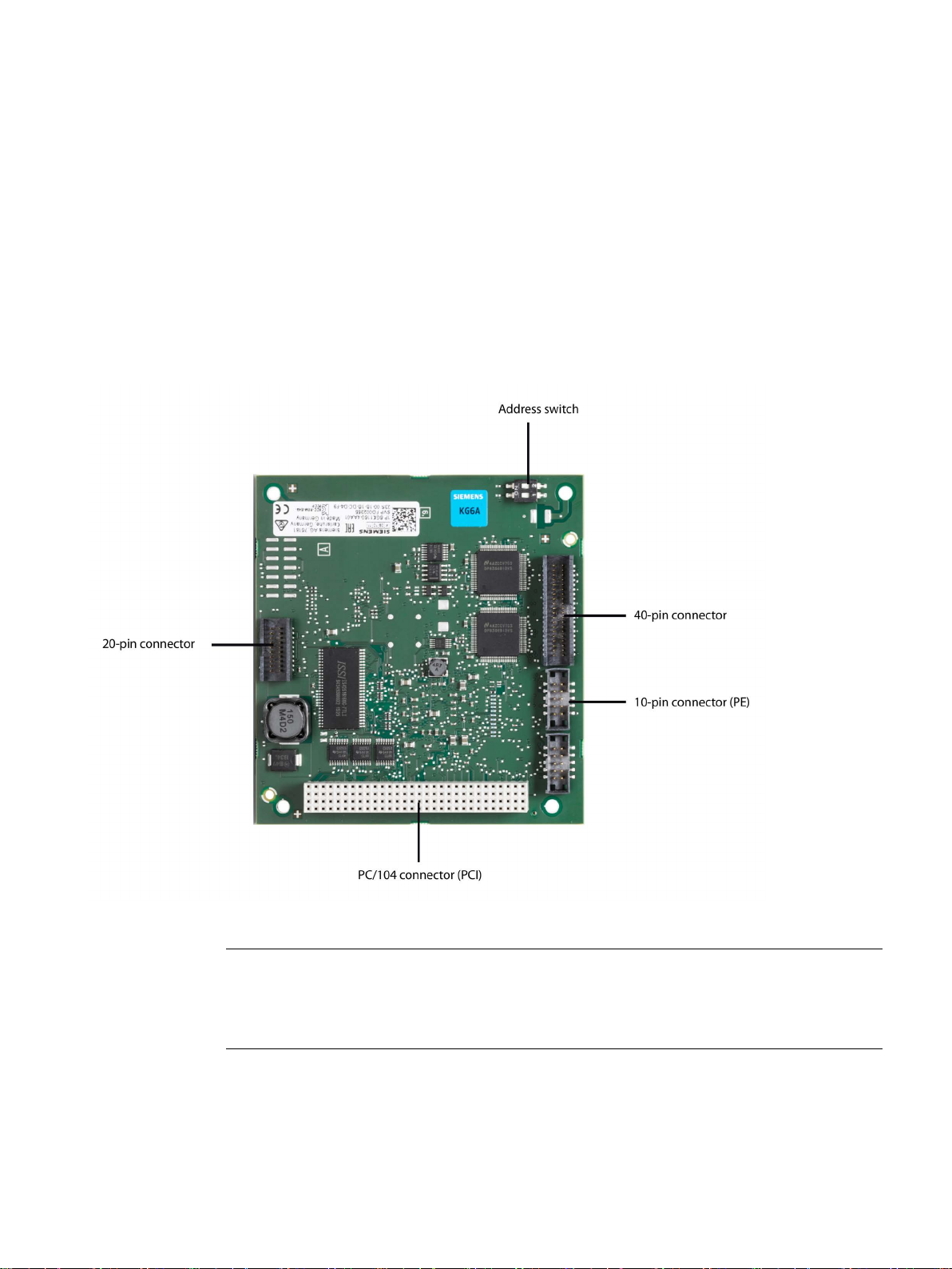
The following graphic shows the CP 1604 communications processor:
r resistance to environmental influences.
CP 1604 / CP 1616
Operating Instructions, 02/2017, C70000-G8976-C218-08
11

Description of the device
Properties
LED display
BF LED
SF LED
Description
off - Communications connection is established.
on
Diagnostics information is available.
the section "Eliminating problems (Page 84)".
alternating slow flashing
Flash test for module detection.
possible.
Note
problem.
1.1 CP 1604 communications processor
The CP 1604 communications processor is a PCI module in the Universal PC/104 Plus
format for connection of PCs in the PC/104 Plus format to Industrial Ethernet. The essential
properties are as follows:
● Optimized for PROFINET IO
● With Ethernet realtime ASIC ERTEC 400
● 40-pin male connector for connection of the RJ-45 connection board for CP 1604
● 20-pin male connector for connection of an external power supply
● 10-pin male connector for the PROFIenergy controller
● Integrated 4-port real-time switch
● Automatic hardware detection is supported.
10 LEDs can be controlled by the CP 1604 communications processor. The LED signal
cables are connected to the 20-pin and 40-pin connectors.
The BF and SF LEDs have the following significance:
on - Link status error has occurred.
flashing slowly - There are two possible causes:
• An IO device cannot be addressed.
• An IP address was assigned twice.
– off There are two possible causes:
• No fault/error.
• A download is in progress.
flashing at 2 second in-
tervals
alternating fast flashing A disruption has occurred.
The firmware of the module is in an inconsistent status.
This status is possible, for example if the power supply was inter-
rupted during a firmware update. Eliminate the error as described in
In this case, diagnostics via the Web or using SNMP is no longer
If this error occurs, contact Technical Support. The problem can be
eliminated if you contact our specialists directly. You will find the
contact data in the section "Preface (Page 3)".
Resetting the firmware or restarting the PC will not eliminate the
CP 1604 / CP 1616
12 Operating Instructions, 02/2017, C70000-G8976-C218-08

Description of the device
LEDs on the "RJ-45 connection board for CP 1604"
Virtual LEDs
1.1.1
40-pin male connector for connection of the RJ-45 connection board for CP 1604
Description
Ethernet connectors
LED signaling
1.1 CP 1604 communications processor
Within the frame of each RJ-45 jack, there are 2 LEDs.
The green LED is lit when a connection is established (Link LED).
The yellow LED is lit when sending and receiving (Activity LED).
Note that apart from the visible LEDs there are also two "virtual" LEDs in the firmware.
These are the operating mode LEDs RUN and STOP. They do not exist physically but can
nevertheless be queried using SNMP. They are on in the RUN or STOP mode and never
flash normally or quickly.
The 40-pin connector is used to connect the ribbon cable from the RJ-45 connection board
for CP 1604. This has the Ethernet connectors that allow network operation.
The signals are processed in the integrated 4-port real-time switch of the CP 1604.
The CP 1604 communications processor is intended for operation in Ethernet networks.
It also has the following features:
● The connectors are designed for 10BaseT and 100BaseTX (via RJ-45 connection board
● Data transmission speeds of 10 and 100 Mbps in full/half duplex are supported.
● The adaptation is automatic (autonegotiation).
● The module includes a 4-port real-time switch.
● Autocrossing
● The CP 1604 can be a PCI master.
If the CP 1604 is used without the RJ-45 connection board for CP 1604, the 40-pin
connector has 2 pins per channel for the Link and Activity signal. These can be used to
control a total of 8 LEDs. The signals of the operating statuses group fault (SF) and bus fault
(BF) are available at pin 3 (SF) and pin 37 (BF).
for CP 1604).
The wiring is the same as described for the 20-pin connector.
CP 1604 / CP 1616
Operating Instructions, 02/2017, C70000-G8976-C218-08
13

Description of the device
Pin assignment of the 40-pin connector
Pin no.
Assignment
Pin no.
Assignment
1
P3V3
21
RDN_P2
3
GPIO(6) – SF
23
M
4
LINK_P0_N
24
TDN_P2
5
ACT_P0_N
25
TDP_P2
6
LINK_P1_N
26 M 7
ACT_P1_N
27
RDN_P3
8 M 28
RDP_P3
9
RDN_P0
29 M 10
RDP_P0
30
TDN_P3
11 M 31
TDP_P3
12
TDN_P0
32
M
13
TDP_P0
33
LINK_P2_N
14 M 34
ACT_P2_N
15
RDN_P1
35
LINK_P3_N
16
RDP_P1
36
ACT_P3_N
17 M 37
GPIO(7) – BF
18
TDN_P1
38
P3V3
19
TDP_P1
39
M
20 M 40
P3V3
1.1.2
20-pin male connector for connection of an external power supply
Description
LED connection (optional)
1.1 CP 1604 communications processor
The pin assignment of the 40-pin connector is as follows:
2 M 22 RDP_P2
You will find the pin assignment of the connector on the labeling on the ribbon cable socket
bar.
The 20-pin connector is used to connect an external power supply as well as 2 LEDs for
signaling the operating statuses bus fault (BF) and group fault (SF). Siemens does not
provide an external power supply for this module.
With the 5 V power supply, the integrated real-time switch can also operate when the PC is
turned off. The 5 V power supply is optional. Without the external 5 V power supply, the
switch operates with the 5 V power supply of the PC/104 PC.
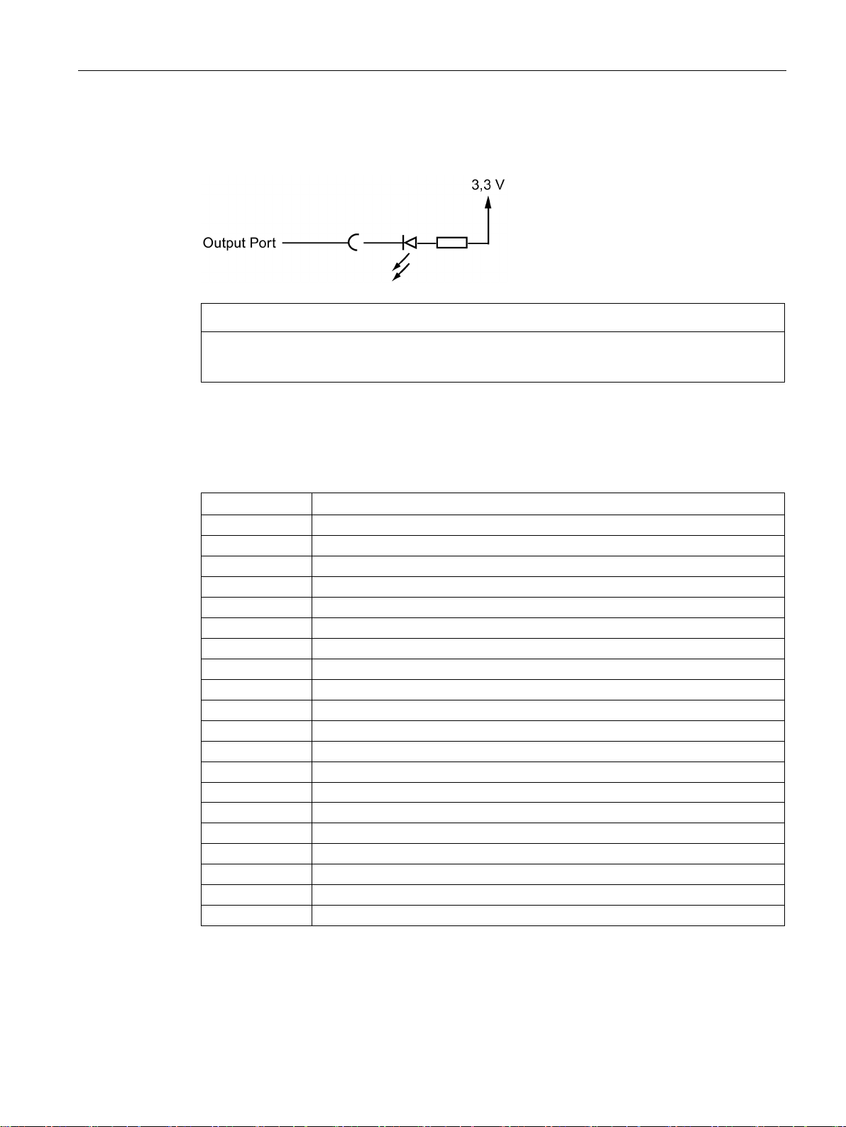
The following figure shows the circuit diagram for connecting an LED to a pin of the 20- or
40-pin connector.
CP 1604 / CP 1616
14 Operating Instructions, 02/2017, C70000-G8976-C218-08
Description of the device
NOTICE
LED current
Pin assignment of the 20-pin connector
Pin no.
Assignment
1
GND
2
GND
3
5 V power supply, +/-5%
4
5 V power supply, +/-5%
5
5 V power supply, +/-5%
6
5 V power supply, +/-5%
7
Connector for SF LED
8
GND
9
Reserved, do not assign!
10
GND
11
Reserved, do not assign!
12
GND
14
GND
15
5 V power supply, +/-5%
16
5 V power supply, +/-5%
17
5 V power supply, +/-5%
18
5 V power supply, +/-5%
20
GND
1.1 CP 1604 communications processor
The CP 1604 activates ground via a port. This means that via the resistor connected to the
3.3 V power supply, the current flows via the LED.
The LED current must not exceed 9 mA.
The pin assignment of the 20-pin connector is as follows:
CP 1604 / CP 1616
Operating Instructions, 02/2017, C70000-G8976-C218-08
13 Connector for BF LED
19 GND
You will find the pin assignment of the connector on the labeling on the ribbon cable socket
bar.
15

Description of the device
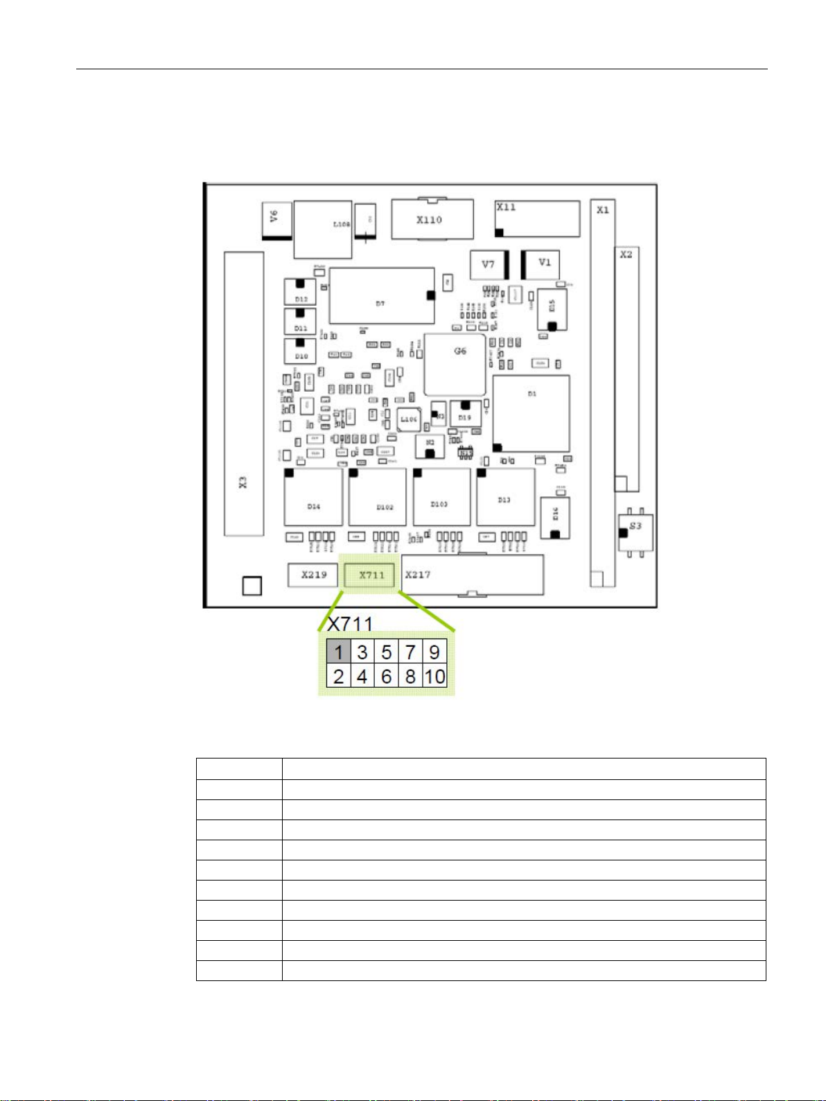
1.1.3
10-pin connector
Description
Note
Hardware version for 10-pin connector
The 10
1.1 CP 1604 communications processor
The 10-pin connector (PE) is used to signal the PROFIenergy commands to the host PC. As
of firmware V2.6, the CP 1604 allows operation as a PROFIenergy device. With suitable
commands from the PROFINET controller, the PC in which the CP 1604 is plugged in can be
turned off and on again with the aim of reducing energy consumption. The device is turned
off by certain commands (data records) on the IO-Base user programming interface. You will
find these commands in the "IO-Base User Programming Interface" document.
-pin connector is available as of hardware version 7 (MLFB 6GK1160-4AA01).
CP 1604 / CP 1616
16 Operating Instructions, 02/2017, C70000-G8976-C218-08
Description of the device
Assignment
PIN number
Remarks
2
PE_WAKE signal
3
Do not connect!
4
Do not connect!
5
Do not connect!
6
Do not connect!
7
Do not connect!
8
Do not connect!
9
Do not connect!
10
Ground
1.1 CP 1604 communications processor
The pin assignment of the 10-pin connector (PE) is as follows:
CP 1604 / CP 1616
Operating Instructions, 02/2017, C70000-G8976-C218-08
Figure 1-1 View of the 10-pin connector (PE) - X711 from above
1 3.3 V
17
Description of the device
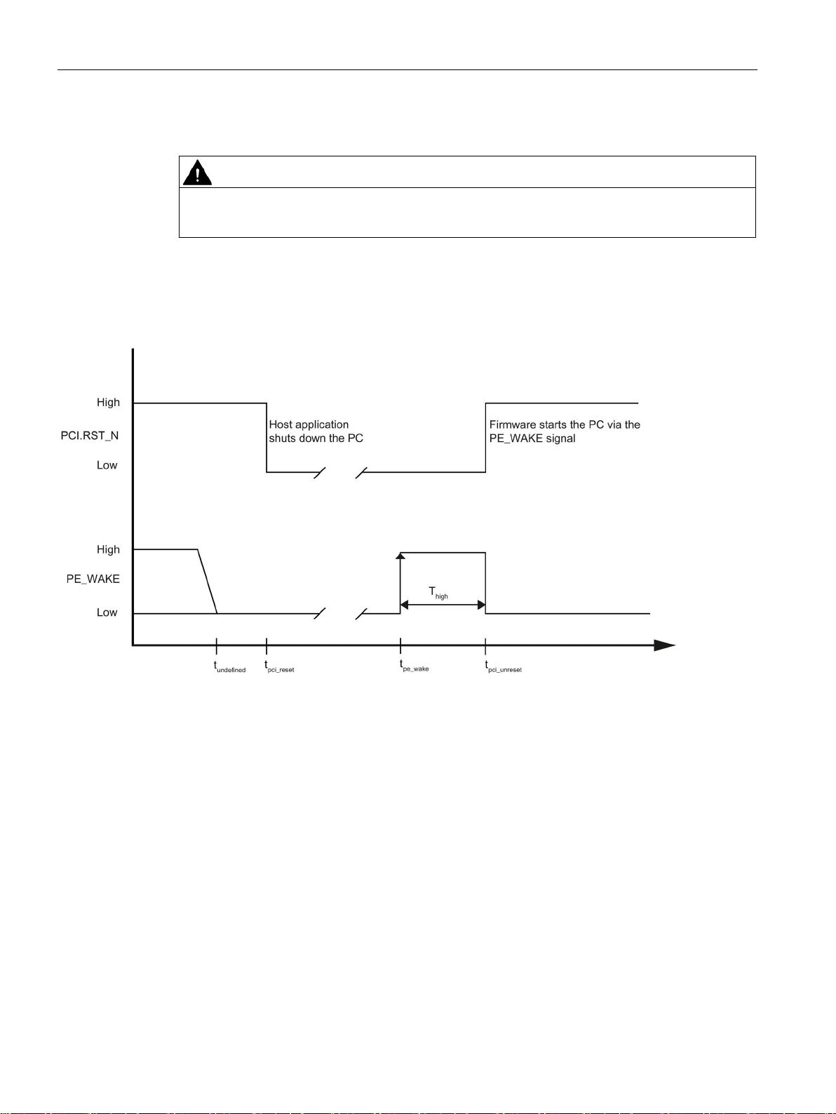
WARNING
Do not connect pins 3 to 9!
Signal description "PE_WAKE"
t
The host application shuts down the PC. The RST_N level on the PCI bus then
falls to "Low".
t
T
startup procedure of the host PC with the PE_WAKE signal.
t
When it restarts, the host PC pulls the RST_N pin on the PCI bus to "High". The
firmware then sets the PE_WAKE signal back to "Low".
t
t
After PC start, the PE_WAKE signal is not defined until this point in time. The
PE_WAKE signal can only be used as controller for switching on the host PC
system after the 12 seconds.
1.1 CP 1604 communications processor
Do not connect pins 3 to 9! Otherwise the CP may be destroyed.
The following diagram represents the "PE_WAKE" signal:
pci_reset
pe_wake
pci_unreset
undefined
CP 1604 / CP 1616
18 Operating Instructions, 02/2017, C70000-G8976-C218-08
he firmware receives the PROFIenergy end pause frame and initiates the
undefined
= 12 seconds
Description of the device
Electrical characteristics
PIN number
Value
Typical
Max
Min
1 I -
20 mA
-
2 I -
5 mA
-
2
U
low
0 V
0.8 V
-
2
U
3.3 V
-
2 V
Mating component of the 10-pin connector (PE)
1.1.4
RJ-45 connection board for CP 1604
Appearance
1.1 CP 1604 communications processor
The 10-pin connector (PE) has the following electrical properties:
1 U 3.3 V - -
high
As the mating component of the 10-pin connector (PE), we recommend the TMM105-xx-SD-x connector from the Samtec company.
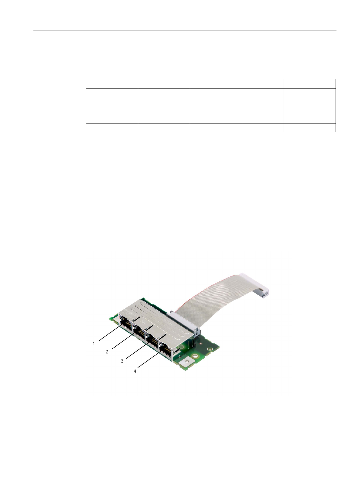
The following figure shows the RJ-45 connection board for the CP 1604 with a 40-pin ribbon
cable and the port number.
CP 1604 / CP 1616
Operating Instructions, 02/2017, C70000-G8976-C218-08
19
Description of the device
Properties
LED description
Meaning
Green LED
Is lit if a connection is established (Link LED).
1.2
CP 1616 communications processor
Appearance
1.2 CP 1616 communications processor
The RJ-45 connection board for the CP 1604 has 4 RJ-45 jacks for connecting end devices
or other network components. With the supplied 40-pin ribbon cable, the RJ-45 connection
board for CP 1604 is connected to the CP 1604.
The signals of the 4 RJ-45 jacks are connected to the integrated real-time switch on the CP
1604.
Apart from the RJ-45 connectors, there are also 2 LEDs (green and yellow) for each port.
Yellow LED Is lit when sending and receiving (Activity LED).
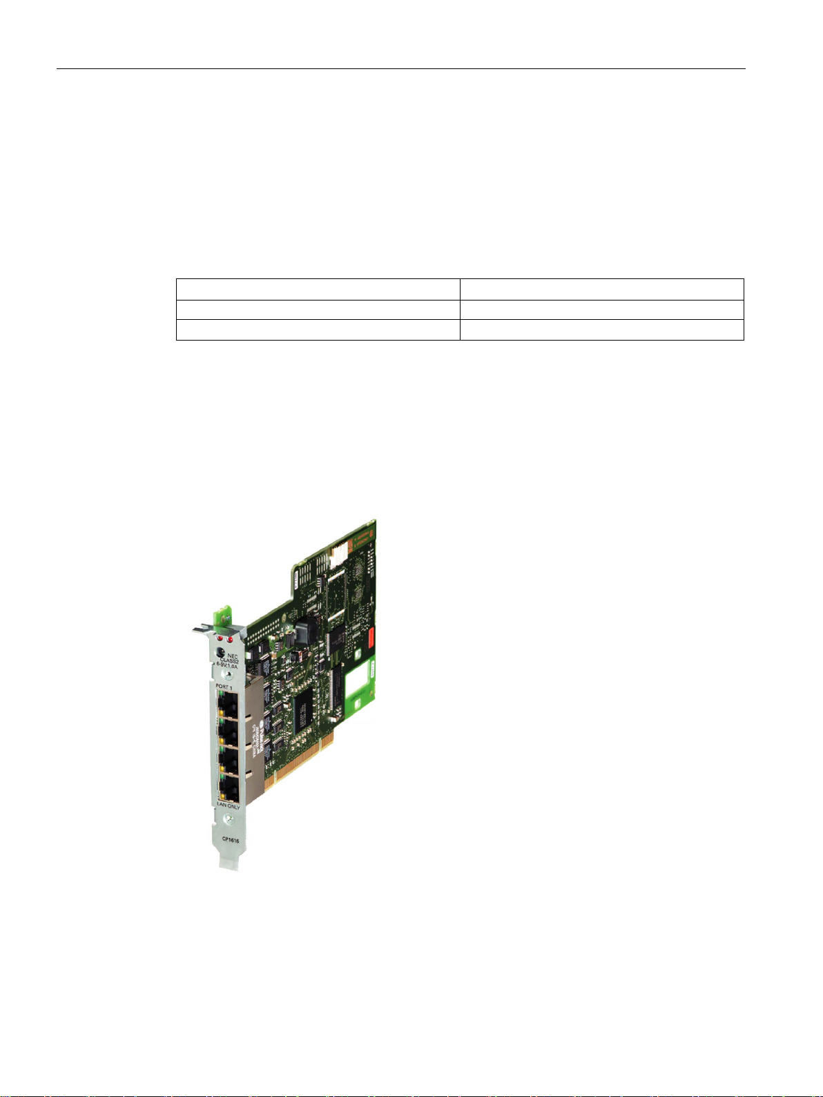
The following figure shows the CP 1616 communications processor.
CP 1604 / CP 1616
20 Operating Instructions, 02/2017, C70000-G8976-C218-08

Description of the device
Properties
Hardware requirements
LED display
LEDs in the frame of each RJ-45 jack
BF LED
SF LED
Description
off - Communications connection is established.
on
Diagnostics information is available.
the section "Eliminating problems (Page 84)".
alternating slow flashing
Flash test for module detection.
1.2 CP 1616 communications processor
The CP 1616 is a PCI module for connecting PGs/PCs to Industrial Ethernet. The essential
properties are as follows:
● Optimized for PROFINET IO
● With Ethernet realtime ASIC ERTEC 400
● Four RJ-45 jacks for connection of end devices or other network components
● Integrated 4-port real-time switch
● Automatic hardware detection is supported
To be able to operate, the CP 1616 requires a 32-bit wide, short PCI slot with master
capability.
On the front of the CP 1616, there are 10 LEDs.
Above the four RJ-45 jacks, there are 2 red LEDs labeled "BF" (bus fault) and "SF" (group
fault).
Within the frame of each RJ-45 jack, there are 2 LEDs.
The upper green LED is lit when a connection is established (Link LED).
The lower yellow LED is lit when sending and receiving (Activity LED).
BF and SF LED
The BF and SF LEDs have the following significance:
on - Link status error has occurred.
flashing slowly - There are two possible causes:
• An IO device cannot be addressed.
• An IP address was assigned twice.
– off There are two possible causes:
• No fault/error.
• A download is in progress.
flashing at 2 second in-
tervals
CP 1604 / CP 1616
Operating Instructions, 02/2017, C70000-G8976-C218-08
The firmware of the module is in an inconsistent status.
This status is possible, for example if the power supply was inter-
rupted during a firmware update. Eliminate the error as described in
21

Description of the device
BF LED
SF LED
Description
possible.
Note
problem.
Virtual LEDs
External power supply
Ethernet
Four RJ-45 jacks
1.2 CP 1616 communications processor
alternating fast flashing A disruption has occurred.
In this case, diagnostics via the Web or using SNMP is no longer
Remember that apart from the LEDs visible on the front panel, there are also two "virtual"
LEDs in the firmware. These are the operating mode LEDs RUN and STOP. They do not
exist physically but can nevertheless be queried using SNMP. They are on in the RUN or
STOP mode and never flash normally or quickly.
The CP 1616 has a socket for connecting an external power supply.
With this power supply, the integrated real-time switch can operate even if the PC is turned
off.
If this error occurs, please contact Technical Support. The problem
can be eliminated if you contact our specialists directly. You will find
the contact data in the section "Preface (Page 3)".
Resetting the firmware or restarting the PC will not eliminate the
The CP 1616 is intended for operation in Ethernet networks.
It also has the following features:
● The connectors are designed for 10BaseT and 100BaseTX.
● Data transmission speeds of 10 and 100 Mbps in full/half duplex are supported.
● Autonegotiation
● The module includes a 4-port real-time switch.
● Autocrossover
The connection of the CP 1616 to the LAN (Local Area Network) is via one of the four RJ-45
jacks on the front panel of the CP.
The four jacks are connected to the integrated real-time switch.
CP 1604 / CP 1616
22 Operating Instructions, 02/2017, C70000-G8976-C218-08
Description of the device
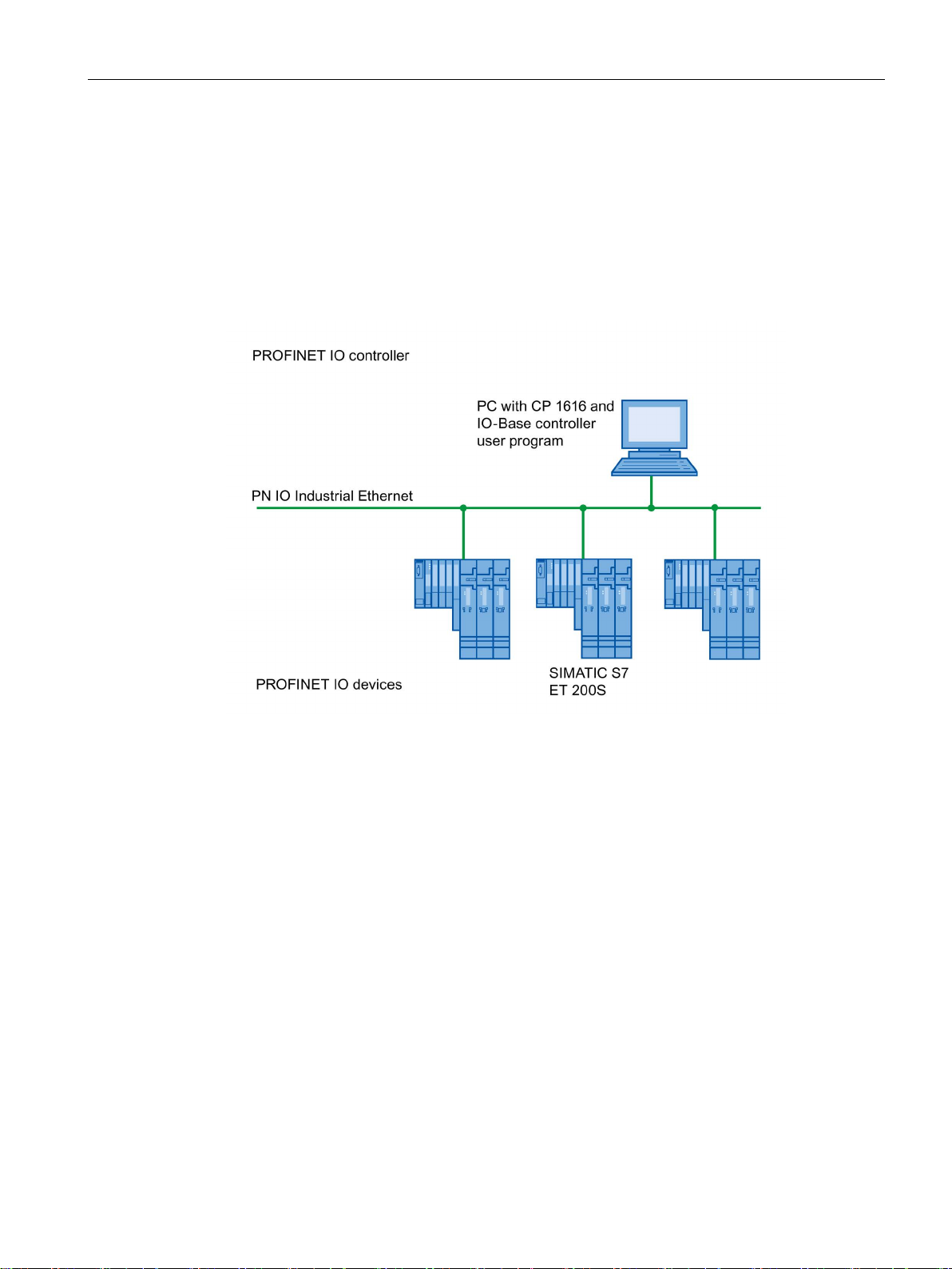
CP 1616 in a PC as IO controller
1.2 CP 1616 communications processor
The following schematic illustrates a typical application:
PC with CP 1616 as PROFINET IO controller at the IO controller level.
The IO-Base controller user program runs on the PC and accesses the functions of the IOBase user programming interface.
The data traffic is handled via a CP 1616 communications processor with several ET 200S
SIMATIC S7 PROFINET IO devices via Industrial Ethernet.
CP 1604 / CP 1616
Operating Instructions, 02/2017, C70000-G8976-C218-08
23
Description of the device
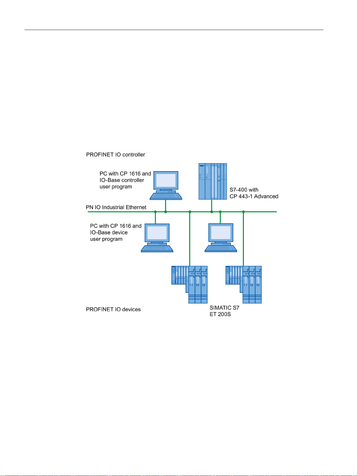
CP 1616 in a PC as IO device
1.2 CP 1616 communications processor
The following schematic illustrates a typical application:
Two PCs each with a CP 1616 as PROFINET IO device at the IO device level.
There is also a PC with a CP 1616 as PROFINET IO controller, a SIMATIC S7-400 with a
CP 443-1 as PROFINET IO controller and two SIMATIC S7 ET 200S PROFINET IO devices
in the network.
On the IO device PCs, there is an IO-Base device user program that accesses the functions
of the IO-Base user programming interface. The data traffic is via a CP 1616
communications processor to a PC as PROFINET IO controller or an S7-400 automation
system with a CP 443-1 via Industrial Ethernet.
CP 1604 / CP 1616
24 Operating Instructions, 02/2017, C70000-G8976-C218-08

2
2.1
CP 1604 communications processor
2.1.1
Important information
Electrostatic sensitive devices
Installing the modules
Read the manual
2.1.2
Requirements and notes
Recommendation for installation when using Linux
Recommendation for installation when using Linux RTAI
Activate the plug and play mechanism
Remember the measures to prevent electrostatic charge when installing the module
(ESD - Electrostatic Discharge)
Opening the PC and plugging or pulling the modules is permitted only when the power is off.
Before installing the module, read the section "Requirements and notes (Page 25)" in the
manual of your PC and the following section completely and keep to the instructions.
Install the CP 1604 communications processor first and then install the CP 1604 driver.
For the integrated graphic chip and the X server (graphic user Interface), we recommend a
VESA-compatible driver to achieve stable IRT operation.
If available, enable the plug-and-play mechanism in the BIOS of your computer.
CP 1604 / CP 1616
Operating Instructions, 02/2017, C70000-G8976-C218-08
25

Hardware installation
Requirement for the PCI slot
Note
Multiple CP 1604 communications processors in one PC are not permitted.
Module address
Module address
Switch 1
Switch 2
Comment
0
On
On - 1
On
Off
-
2
Off
On
-
3
Off
Off
Not permitted!
Note
Make sure that all the module addresses in the stack are set differently.
Note
With certain variants of the SIMATIC Microbox, is not possible to use all module addresses;
you will find further
Note
Multiple CP 1604 communications processors in one PC are not permitted.
Note
If you use a PCI adapter, you should ideally set module address 0.
2.1.3
Procedure for installing the CP 1604
Installation and connection of the CP 1604
2.1 CP 1604 communications processor
The CP 1604 communications processor requires a PCI slot in the PC/104 Plus format.
The module address is set with the address switch as described below:
information on this in the appropriate operating instructions.
Follow the steps below when installing and connecting up the CP 1604 communications
processor in the SIMATIC Microbox PC 420:
1. Turn off your computer and pull out the power cable connector from the socket.
2. Open the computer housing as described in the manual accompanying your PC.
CP 1604 / CP 1616
26 Operating Instructions, 02/2017, C70000-G8976-C218-08

Hardware installation
Note
When handling the module, make sure that you do not touch the con
electronic components.
2.2
CP 1616 communications processor
2.2.1
Important information
Electrostatic sensitive devices
Installing the CP 1616
Read the manual
External power supply
2.2 CP 1616 communications processor
3. Remove the CP 1604 communications processor from its packaging.
nectors or the
4. When necessary screw the supplied threaded sleeves onto the module on which the CP
1604 will be placed.
5. Insert the CP 1604 into the prepared PC/104 Plus slot.
Make sure that the CP 1604 sits firmly and uniformly.
6. Take the 4 supplied M3 screws and screw the CP 1604 to the underlying sleeves.
7. Set the module address on the CP 1604.
8. When required, install the Microbox expansion frame for the CP 1604 with the optional
CP 1604 modules as described in the section "AUTOHOTSPOT".
9. Close the computer housing as described in the manual accompanying your PC.
10.If required, insert the connecting cables (TP) in the corresponding RJ-45 jacks of the RJ45 connection board for the CP 1604.
11.Plug the power supply connector into the socket again and turn on your computer.
Please remember the measures to prevent electrostatic charge when installing the module
(ESD - Electrostatic Discharge)
Opening the PC and plugging or pulling the modules is permitted only when the power is off.
Before installing the module, please read the section "Procedure for installing the CP 1616
(Page 28)" or similar in the manual of your PC and keep to the instructions.
The CP 1616 has a socket for connecting an external power supply.
CP 1604 / CP 1616
Operating Instructions, 02/2017, C70000-G8976-C218-08
27

Hardware installation
NOTICE
UL approval
2.2.2
Procedure for installing the CP 1616
WARNING
Do not put any damaged parts into operation!
Recommendation for installation when using Linux
Requirements and conditions
Note
Note on the number of possible CP 1616s in one computer
A maximum of one CP 1616 module can be installed in one PG/PC.
Installation and connection of the CP 1616
2.2 CP 1616 communications processor
With this power supply (6 to 9 VDC), the CP 1616 can operate as a switch even if the PC is
turned off.
These modules are intended for installation in Siemens PCs which are approved in
accordance with UL 508 and listed under UL file number E85972. These PCs must comply
with the UL 508 guidelines on "limited voltage / current" or have an "LPS supply" in
accordance with UL 60950 or a "Class 2 supply" in accordance with UL 1310/UL 1885.
Do not use any parts that show evidence of damage!
Install the CP 1616 first and then install the CP 1616 driver.
● If available, enable the plug-and-play mechanism in the BIOS of your computer.
● The CP 1616 communications processor requires a PCI slot with master capability.
To install and connect up the CP 1616 follow the steps outlined below:
1. Turn off your computer and pull out the power cable connector from the socket.
2. Open the computer housing as described in the manual accompanying your PG/PC.
3. Remove the cover of a free PCI slot in your computer.
CP 1604 / CP 1616
28 Operating Instructions, 02/2017, C70000-G8976-C218-08
 Loading...