

Page 1

SIMATIC NET
CP 142-2
Manual
1 Introduction
2 Technical Description and Installation Instructions
3 Standard Operation
4 Extended Operation
5 Replacing a Defective Slave / Automatic Address Programming
6 Error Indicators / Dealing with Errors
7 PROFIBUS DP Configuration When Using the
BM141/BM142
A AS-Interface Protocol Implementation
Conformance Statement (PICS)
B References
C Abbreviations
C79000-G8976-C111 Release 02
SIMATIC NET is a trademark of Siemens
Siemens Aktiengesellschaft
Page 2

Wir haben den Inhalt der Druckschrift auf
Übereinstimmung mit der beschriebenen Hard- und
Software geprüft. Dennoch können Abweichungen
nicht ausgeschlossen werden, so daß wir für die
vollständige Übereinstimmung keine Gewähr
übernehmen. The Angaben in der Druckschrift
werden jedoch regelmäßig überprüft. Notwendige
Korrekturen sind in den nachfolgenden Auflagen
enthalten. Für Verbesserungsvorschläge sind wir
dankbar.
Technische Änderungen vorbehalten.
Weitergabe sowie Vervielfältigung dieser Unterlage,
Verwertung und Mitteilung ihres Inhalts nicht gestattet,
soweit nicht ausdrücklich zugestanden.
Zuwiderhandlungen verpflichten zu Schadenersatz.
Alle Rechte vorbehalten, insbesondere für den Fall
der Patenterteilung oder GM-Eintragung.
C79000-G8900-C111
Copyright © Siemens AG 1997
All Rights Reserved
We have checked the contents of this manual for
agreement with the hardware described. Since
deviations cannot be precluded entirely, we cannot
guarantee full agreement. However, the data in this
manual are reviewed regularly and any necessary
corrections included in subsequent editions.
Suggestions for improvement are welcome.
Technical data subject to change.
Nous avons vérifié la conformité du contenu du
présent manuel avec le matériel et le logiciel qui y
sont décrits. Or, des divergences n'étant pas exclues,
nous ne pouvons pas nous porter garants pour la
conformité intégrale. Si l'usage du manuel devait
révéler des erreurs, nous en tiendrons compte et
apporterons les corrections nécessaires dès la
prochaine édition. Veuillez nous faire part de vos
suggestions.
Nous nous réservons le droit de modifier les
caractéristiques techniques.
The reproduction, transmission or use of this
document or its contents is not permitted without
express written authority. Offenders will be liable for
damages. All rights, including rights created by patent
grant or registration of a utility or design, are reserved.
C79000-G8976-C111
Copyright © Siemens AG 1997
All Rights Reserved
Toute communication ou reproduction de ce support
d'informations, toute exploitation ou communication
de son contenu sont interdites, sauf autorisation
expresse. Tout manquement à cette règle est illicite et
expose son auteur au versement de dommages et
intérêts. Tous nos droits sont réservés, notamment
pour le cas de la délivrance d'un brevet ou celui de
l'enregistrement d'un modèle d'utilité.
C79000-G8972-C111
Copyright © Siemens AG 1997
All Rights Reserved
Siemens Aktiengesellschaft Elektronikwerk Karlsruhe
Printed in the Federal Republic of Germany
Page 3

SIMATIC NET
CP 142-2
Manual
C79000-B8976-C111/02
Page 4

We would point out that the contents of this product documentation shall not become a part of or modify any prior or existing
agreement, commitment or legal relationship. The Purchase Agreement contains the complete and exclusive obligations of
Siemens. Any statements contained in this documentation do not create new warranties or restrict the existing warranty.
We would further point out that, for reasons of clarity, these operating instructions cannot deal with every possible problem arising
from the use of this device. Should you require further information or if any special problems arise which are not sufficiently dealt
with in the operating instructions, please contact your local Siemens representative.
General
WARNING!
This device is electrically operated. In operation, certain parts of this device carry a dangerously high voltage.
Failure to heed warnings may result in serious physical injury and/or material damage.
!
Only appropriately qualified personnel may operate this equipment or work in its vicinity. Personnel must be
familiar with all warnings and maintenance measures in accordance with these operating instructions.
Correct and safe operation of this equipment requires proper transport, storage and assembly as well as
careful operator control and maintenance.
Personnel qualification requirements
Qualified personnel as referred to in the operating instructions or in the warning notes are defined as persons who are familiar with
the installation, assembly, startup and operation of this product and who possess the relevant qualifications for their work, e.g.:
− Training in or authorization for connecting up, grounding or labeling circuits and devices or systems in accordance with current
standards in safety technology;
− Training in or authorization for the maintenance and use of suitable safety equipment in accordance with current standards in
safety technology;
− First Aid qualification.
Page 5

B8976111/02 Contents
Contents
1 Introduction 1-1
1.1 General 1-2
1.1.1 Overview of the Chapters 1-2
1.1.2 General Information for the Reader 1-3
1.1.3 Requirements for Understanding the Manual 1-4
1.1.4 Sample Programs 1-5
1.1.5 Further Support and Hotline 1-5
2 Technical Description and Installation Guidelines 2-1
2.1 Overview of the Module 2-2
2.1.1 Introduction 2-2
2.1.2 Technical Specifications of the Module 2-3
2.1.3 Installing and Connecting the CP 142-2 2-4
2.1.4 Indicators and Operator Controls on the CP 142-2 2-6
2.1.4.1 Meaning of the Indicators and Operator Controls: 2-6
2.1.4.2 Status Display of the CP 142-2 (all group LEDs off) 2-7
2.1.4.3 Slave Display of the CP 142-2 (at least on group LED lit) 2-8
2.1.4.4 Meaning of theSET/DISPLAY Button 2-9
2.1.4.5 Slots Permitted for the CP 142-2 in the ET 200X Distributed I/O Station 2-9
2.1.4.6 Configuring the AS-Interface with the SET/DISPLAY Button 2-9
2.1.4.7 Types of Operation with the CP 142-2 2-11
3 Standard Operation of the CP 142-2 3-1
3.1 Addressing the CP 142-2 3-1
3.1.1 Addressing using the BM141/BM142 3-1
3.1.2 Addressing when using the BM147 3-1
3.2 How the User Program Addresses the AS-i Slaves 3-2
3.2.1 Addressing AS-i User Data 3-2
3.2.2 Accessing the AS-i User Data (BM141, BM142) 3-4
3.2.3 Access to the AS-i User Data (BM147) 3-5
3.3 Diagnostics and Reaction to Interrupts on the CP 142-2 3-6
3.3.1 Diagnostics and Reaction to Interrupts with the BM141/BM142 3-6
3.3.1.1 Interrupt Events 3-6
3.3.1.2 Structure of PROFIBUS DP Slave Diagnostics 3-7
3.3.2 Diagnostics and Reaction to Interrupts with the BM147 3-10
3.3.2.1 Overview 3-10
3.3.2.2 Interrupt Events 3-10
3.3.2.3 Sequence of Diagnostic Interrupt Servicing 3-11
3.3.2.4 Response to Interrupts in Various CP States 3-11
3.3.2.5 Local Data of the Diagnostic Organization Block (OB82) 3-12
3.3.2.6 Reading the Diagnostic Data Record DS1 3-13
3.3.2.7 Programming Example 3-14
4 CP 142-2 Extended Operation with FC “ASI_3422” 4-1
4.1 Overview of the Functions 4-1
4.1.1 Calling the Function 4-1
4.2 Interface for AS-i commands 4-7
4.2.1 The Commands Supported by the CP 142-2 4-7
4.2.1.1 Set_Permanent_Parameter 4-8
4.2.1.2 Get_Permanent_Parameter 4-8
4.2.1.3 Write_Parameter 4-9
4.2.1.4 Read_Parameter 4-9
I-1
Page 6

B8976111/02 Contents
4.2.1.5 Store_Actual_Parameters 4-10
4.2.1.6 Set_Permanent_Configuration 4-10
4.2.1.7 Get_Permanent_Configuration 4-11
4.2.1.8 Store_Actual_Parameters 4-11
4.2.1.9 Read_Actual_Configuration 4-12
4.2.1.10 Set_LPS 4-12
4.2.1.11 Set_Offline_Mode 4-13
4.2.1.12 Set_Auto_Address 4-14
4.2.1.13 Set_Operation_Mode 4-14
4.2.1.14 Change_Slave_Address 4-15
4.2.1.15 Read Slave Status 4-16
4.2.1.16 Read Lists and Flags (Get_LPS, Get_LAS, Get_LDS, Get_Flags) 4-17
4.2.1.17 Read Total Configuration 4-19
4.2.1.18 Configure Total System 4-21
4.2.1.19 Write Parameter List 4-24
4.2.1.20 Read Parameter Echo List 4-25
4.2.1.21 Read Version ID 4-26
4.2.1.22 Read and Reset Slave Status 4-27
4.2.1.23 Read Slave ID 4-28
4.2.1.24 Read Slave I/O 4-28
5 Replacing a Defective Slave / Automatic Address Programming 5-1
6 Error Indicators on the CP 142-2 / Dealing with Errors 6-1
7 Configuring PROFIBUS DP When Using the BM141/BM142 7-1
A AS-Interface Protocol Implementation Conformance Statement (PICS)
B References
C Abbreviations
I-2
Page 7

B8976111/02 AS-i Master Module CP 142-2
1 Introduction
This manual describes the functions and the programming of the CP 142-2. To fully understand this
manual, you should be familiar with the manual ‘AS-Interface Introduction and Basic Information’.
We recommend the following procedure when...
´
...You want a general overview of the
AS-Interface.
Read the manual ‘AS-Interface
Introduction and Basic Information'.
This manual contains general
information about the
generally referred to as
manual.
AS-Interface
AS-i
in this
,
...You want to install and start up the CP
142-2.
...You want to know how to program the
CP 142-2.
...you want to create a PLC program for
standard applications.
...you require additional information about
extended operation.
´
Chapter 2 Section 2.1 ‘Overview of the
Module’ and Chapter 3 ‘Standard
Operation of the CP 142-2’ contain the
information you require.
´
Read Chapters 3 and 4.
´
Chapter 3 contains all the information
you require about standard operation.
´
You will find the required information in
Chapter 4.
1-1
Page 8

B8976111/02 AS-i Master Module CP 142-2
1.1 General
1.1.1 Overview of the Chapters
Chapter 1 Introduction
This chapter explains how to make the best use of the manual.
Chapter 2 Technical Description and Installation Guidelinesn
Chapter 2 provides you with an overview of the modes, installation and startup and the indicators and
operator controls of the CP 142-2.
Chapter 3 Standard Operation of the CP 142-2
Chapter 3 describes how to operate the CP 142-2 in the ET 200X distributed I/O system in standard
operation.
Chapter 4 CP 142-2 Extended Operation with FC “ASI_3422”
Chapter 4 describes the extended operation of the CP 142-2, that requires the
FC “ASI_3422” in the control program. In this type of operation, the AS-i slaves can be assigned
parameters or the slave addresses can be modified by the S7 program.
This mode is only possible with the BM147.
Chapter 5 Replacing a Defective Slave / Automatic Address Programming
Chapter 5 explains how to replace a failed AS-i slave quickly and simply.
Chapter 6 Error Indicators on the CP 142-2 / Dealing with Errors
This chapter explains the possible error indications on the CP 142-2 and explains how to deal with
them.
Chapter 7 PROFIBUS DP Configuration When Using the BM141/BM142
Chapter 7 contains additional information about DP configuration of the BM141/BM142.
1-2
Page 9

B8976111/02 AS-i Master Module CP 142-2
1.1.2 General Information for the Reader
General symbols in the text:
This symbol indicates an action for you to perform.
This symbol highlights special features and dangers.
1-3
Page 10

B8976111/02 AS-i Master Module CP 142-2
1.1.3 Requirements for Understanding the Manual
To fully understand the manual, you should already be familiar with the following:
±
The manual ‘AS-Interface Introduction and Basic Information’.
±
The manual 'ET 200X Distributed I/O System’
1-4
Page 11

B8976111/02 AS-i Master Module CP 142-2
1.1.4 Sample Programs
The diskette shipped with this manual contains sample programs which will help you to program the
CP 142-2 when this is installed in a distributed ET 200X I/O system with preprocessing (for example
BM147).
1.1.5 Further Support and Hotline
Who to Contact
Frequently Asked
Questions
Hotline
If you have technical questions about using the product described
here, please contact your local Siemens representative.
The addresses are listed:
➢
in our catalog IK 10
➢
on the Internet (http://www.ad.siemens.de)
Our customer support on the Internet provides useful information and
answers to frequently asked questions (FAQ). Under FAQ, you will find
information about our entire range of products.
The address of the A&D home page in the World Wide Web of the
Internet is as follows:
http://www.ad.siemens.de/net
Our hotline is also available to deal with problems:
➢
Telephone:0911 - 895 - 7000
(outside Germany +49 - 911 - 895 - 7000)
➢
Telefax: 0911 - 895 - 7001
(outside Germany +49 - 911 - 895 - 7001)
➢
E-Mail: simatic.support@nbgm.siemens.de
➢
Mailbox (BBS, analog/ISDN, 8N1):
0911 - 895 - 7100
(outside Germany +49 - 911 - 895 - 7100)
1-5
Page 12

B8976111/02 AS-i Master Module CP 142-2
2 Technical Description and Installation Guidelines
This chapter outlines the performance of the CP 142-2, explains how to install the module and
introduces you to its basic functions.
You will learn the following:
±
How to install the CP 142-2.
±
Which modes are supported by the CP 142-2.
When handling and installing the module, please keep to the general guidelines for
handling electrostatically sensitive devices and follow the instructions in the ‘ET 200X
Distributed I/O System’ manual /4/.
Insert or remove modules only when the power is turned off.
Noise immunity/grounding
To ensure the noise immunity of the CP 142-2, the ET 200X distributed I/O system and
the AS-i power supply unit must be correctly grounded.
The CP 142-2 cannot be operated with all variants of the basic modules of the ET 200X
distributed I/O system. Please read the accompanying Product Information.
The AS-i power supply unit used must provide a low voltage, safely isolated from the
network. This safe isolation can be implemented according to the following
requirements:
±
VDE 0100 Part 410 = HD 384-4-4 = IEC 364-4-41
(as functional extra-low voltage with safe isolation) or
±
VDE 0805 = EN 60950 = IEC 950
(as safety extra-low voltage - SELV) or
±
VDE 0106 Part 101
2-1
Page 13
B8976111/02 AS-i Master Module CP 142-2
2.1 Overview of the Module
2.1.1 Introduction
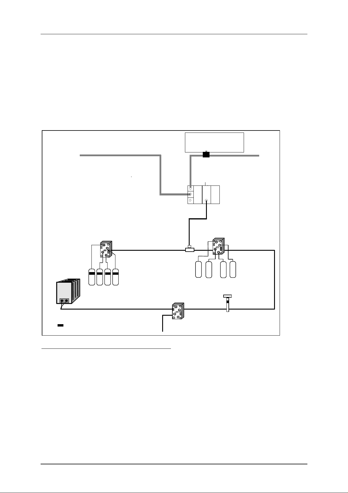
The CP 142-2 module can be operated in the ET 200X distributed I/O system. It allows the
connection of an AS-i chain to the I/O device. The special feature of the ET 200X distributed I/O
system is its rugged construction complying with safety classes IP 65, IP 66 and IP 67.
PROFIBUS
AS-i power
supply unit
Passive AS-i application module
(without slave ASIC)
AS-i cable
(4 x slaves)
Binary sensors and actuators
w ith slave ASIC
A ctive or pass i v e
AS -Interface application modu le
PROFIBUS-DP master
PROFIBUS
CP 142-2
ET 200X
Round cable
Active
AS-i appl. mod ule
(with slave ASIC)
Binary sensors and actuators
without slave ASIC
Actuator or sensor
= Slave ASIC
Figure 2-1 Use of the Master Module CP 142-2 in the ET 200X
AS-i cable
adapter
with direct connection
Components Supplied
The product CP 142-2 consists of the following:
1. CP 142-2 module
2. Product Information bulletin
The STEP 7 block FC “ASI_3422” required for extended operation of the CP 142-2 is shipped with
this manual.
2-2
Page 14

B8976111/02 AS-i Master Module CP 142-2
2.1.2 Technical Specifications of the Module
The CP 142-2 module has the following characteristics:
Bus cycle time 5 ms with 31 slaves
Configuration of the AS-Interface with buttons on the front panel
Supported AS-i master profiles M0 for operation with the bus modules
BM141/BM142
M0/M1 when using the bus module BM147
and FC “ASI_3422”
Connection of the AS-i cable M12 male connector (integrated on the CP
142-2)
Address range 16 input bytes and 16 output bytes
Power supply for the CP 142-2 (via
electronics/ sensor power supply of the ET
200X)
Current consumption from electronics/
sensor power supply
Load voltage of the ET 200X not required for the CP 142-2
Power supply from the AS-i cable
Current consumption from the AS-i cable
Type of protection IP65, IP66, IP67
Ambient conditions
DC 24 V
max. 60 mA
according to the AS-i specification
max. 100 mA
(with the cover of the button in place)
•
Operating temperature
•
Transportation and storage temperature
•
Relative humidity
Construction
•
Module format
•
Dimensions (W x H x D) in mm
•
Weight
Table 2-1 Technical Specifications
0 to 55°C
-40°C to +70°C
max. 95% at +25°C
ET 200X-compatible
87 x 110 x 63
approx. 310 g
2-3
Page 15
B8976111/02 AS-i Master Module CP 142-2
2.1.3 Installing and Connecting the CP 142-2
The assembly of the module and connection to the ET 200X distributed I/O system is the same as for
other expansion modules. For more detailed information, please refer to the “ET 200X Distributed I/O
System” manual /4/.
There are several ways of attaching to the AS-i bus and two possible methods are described here.
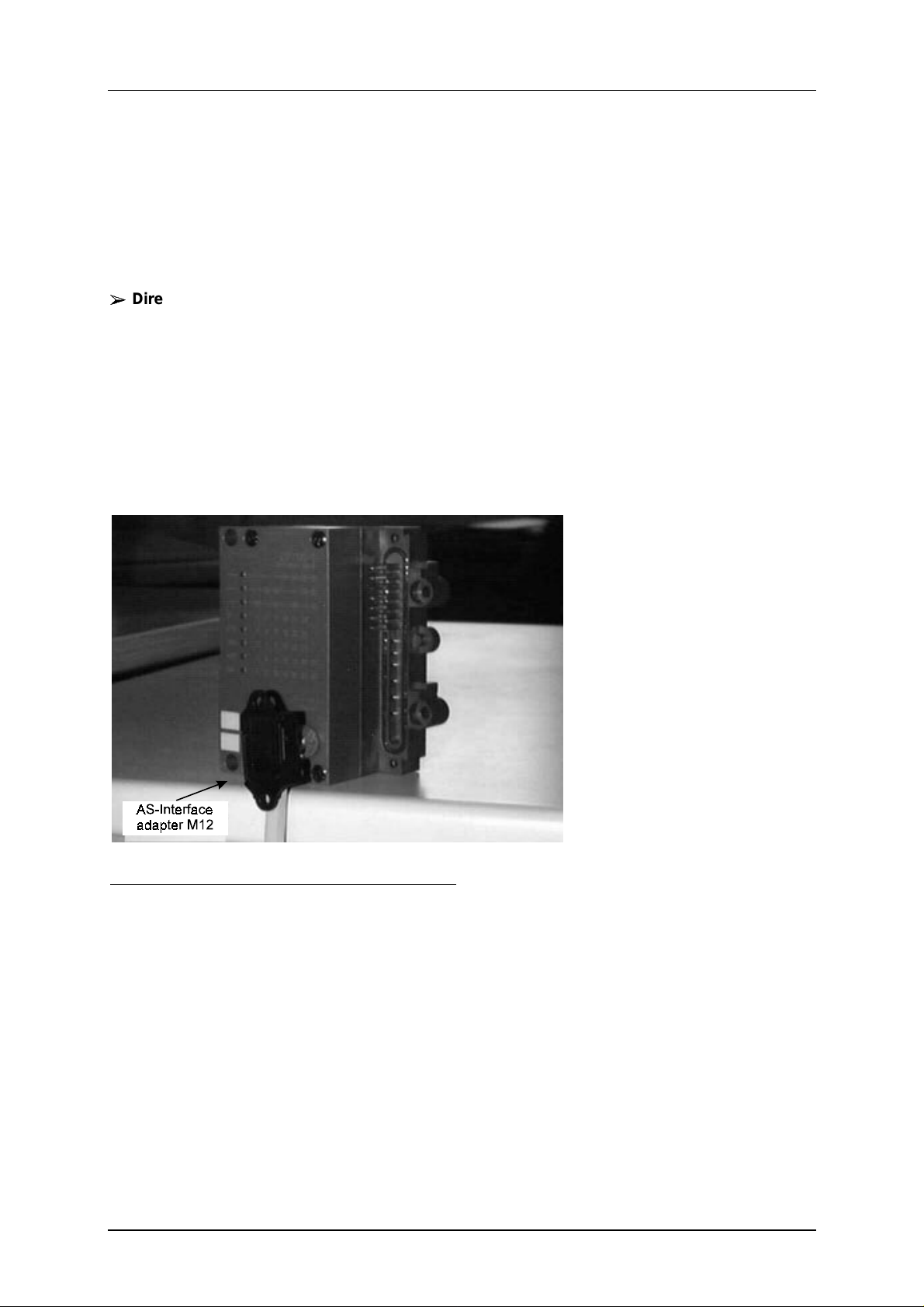
Direct attachment to the AS-i cable using the AS-Interface adapter M12
±
±
You attach an AS-Interface adapter M12 to the AS-i cable to change from the flat cable to the
M12 connection and screw this directly to the connector on the CP 142-2 . Follow the
instructions in the installation guide shipped with the adapter. Remember the following point:
The AS-Interface adapter M12 is often the end of an AS-i chain. In this case, insert the rubber
stopper in the open end of the adapter as explained in the installation guide.
Before you screw the AS-Interface adapter M12 in place, make sure that after it is screwed to
the connector of the CP 142-2, the AS-i cable exits downwards and not towards the neighboring
module. If the cable does exit towards the neighboring module, rotate the connection in the
adapter through 90° as explained in the installation guide.
Figure 2-2 Direct Attachment of the AS-i Cable to the CP 142-2
2-4
Page 16
B8976111/02 AS-i Master Module CP 142-2
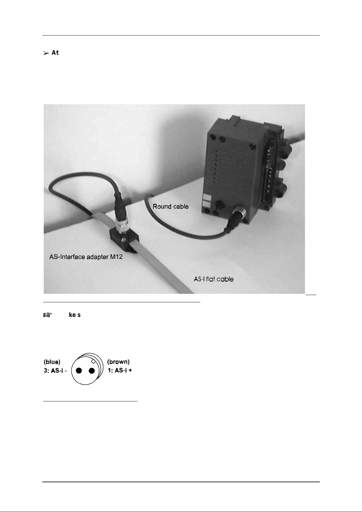
Attaching to the AS-i cable at a distance from the AS-Interface adapter
±
The AS-Interface adapter M12 is first connected to the AS-i shaped cable. A round (sensor)
cable with an M12 male and female connector is used to attach the CP 142-2.
When laying the AS-i cable, make sure that there is adequate strain relief particularly at the end
connected to the CP 142-2.
The product information bulletin contains ordering data for the AS-Interface adapter M12.
e 2-3 Connecting the CP 142-2 to the AS-i Cable via a Round Cable
Make sure that you do not cross-thread the socket when you screw it on to the module,
otherwise the thread of the connector on the module can be damaged.
Figure 2-4 AS-i Connector on the CP 142-2
Figur
2-5
Page 17
B8976111/02 AS-i Master Module CP 142-2
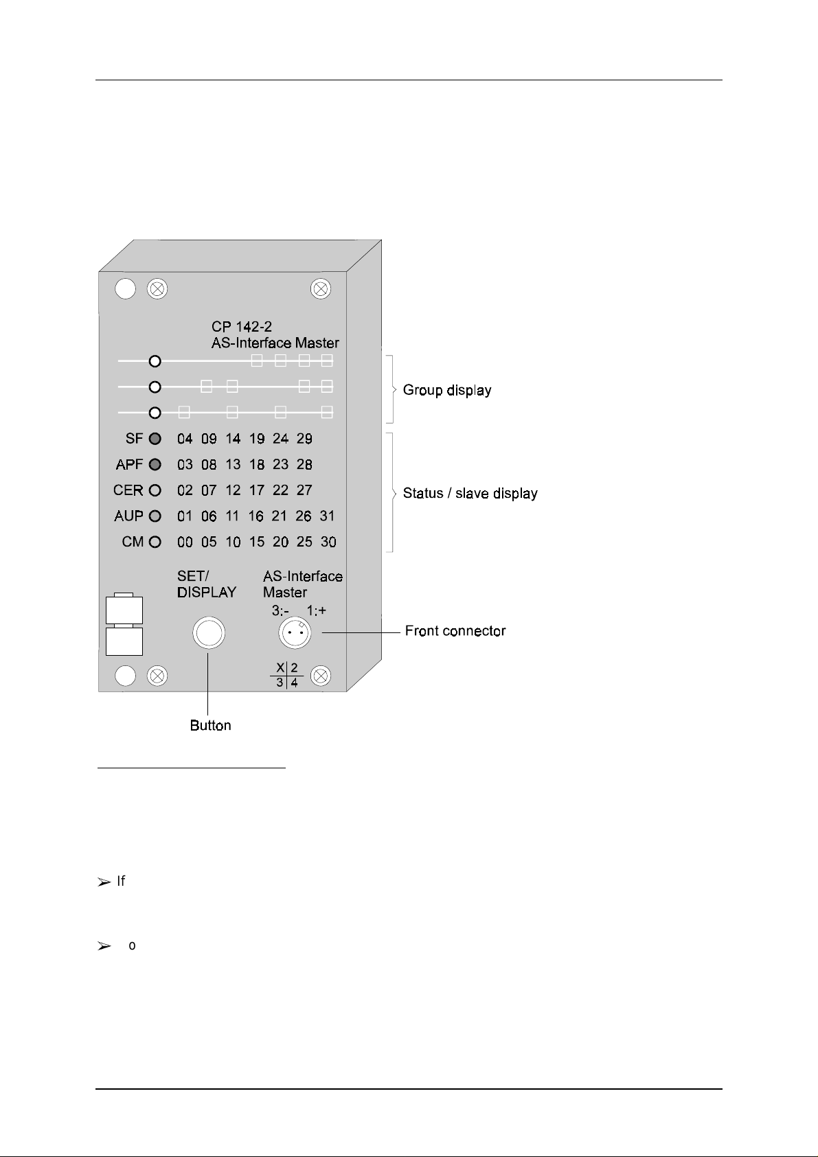
2.1.4 Indicators and Operator Controls on the CP 142-2
Figure 2.5 shows the front panel of the CP 142-2 with its indicators and operator controls.The front
connector for attaching the AS-i cable is at the lower right of the front panel.
To the left of the connector is the SET/DISPLAY button under a screw-on cover.
Figure 2-5 Front View of the CP 142-2
2.1.4.1 Meaning of the Indicators and Operator Controls:
On the front panel of the CP 142-2, there is a line of 8 LEDs. The upper three LEDs are the group
display. The meaning of the lower five LEDs depends on the status of the group display, as follows:
±
If no LED is lit in the group display, the lower five 5 LEDs indicate the status of the CP 142-2
(status display of the CP 142-2). The label to left of the LEDs then applies. The default display is
the status display.
±
If one or more of the LEDs in the group display are it, the lower five LEDs indicate the slaves
detected or active on the AS-Interface (slave display of the CP 142-2); the label to right of the
LEDs then applies.
You can toggle the display with the SET/DISPLAY button. The SET/DISPLAY button is also required
to configure the CP 142-2. If the button is not pressed for approximately 10 minutes, the CP 142-2
automatically switches to the status display.
2-6
Page 18

B8976111/02 AS-i Master Module CP 142-2
2.1.4.2 Status Display of the CP 142-2 (all group LEDs off)
SF (red) System error. The LED is lit when:
±
the CP 142-2 is in the protected mode and an AS-i configuration error
has occurred (for example slave failed)
±
the CP 142-2 detects an internal fault (for example EEPROM defective)
±
The CP 142-2 cannot change to the mode requested with a control
button (for example a slave exists with address 0).
±
Briefly when changing to the protected mode
±
When the CP is in the protected mode in the offline phase
APF (red) AS-i Power Fail. This indicates that the voltage supplied to the AS-i cable by
the AS-i power supply unit is too low or there is a complete power outage.
CER (yellow) Configuration Error. The LED is lit when the slave configuration detected on
the AS-i cable deviates from the desired configuration set on the CP 142-2
(LPS).
The CER indicator is lit in the following situations:
±
when a configured AS-i slave does not exist on the AS-i cable (for
example slave failed)
±
when a slave exists on the AS-i cable but it has not been configured
±
when a connected slave has configuration data (I/O configuration, ID
code) that are different from those of the slave configured on the
CP 142-2
±
briefly when changing to the protected mode
±
When the CP is in the offline phase.
AUP (green) Autoprog available. In the protected mode of the CP 142-2, this indicates
that automatic address programming of a slave is possible. Automatic
address programming makes it easier to replace a defective slave on the
AS-i cable (for more detailed information, see Chapter 5).
CM (yellow) Configuration Mode. This LED indicates the mode.
Indicator lit: configuration mode
Indicator off: protected mode
The configuration mode is only required when installing and starting up the CP 142-2. In the
configuration mode, the CP 142-2 activates all connected slaves and exchanges data with them. For
more detailed information about the configuration mode / protected mode, refer to Section 2.1.4.6.
2-7
Page 19
B8976111/02 AS-i Master Module CP 142-2
play
p
play
2.1.4.3 Slave Display of the CP 142-2 (at least on group LED lit)
The display of the detected or active slaves is in groups of five. The upper three group LEDs indicate
which group of five is displayed. The lower five LEDs indicate the slaves within the group. You
change to the slave display mode by pressing the SET/DISPLAY button. By pressing the
SET/DISPLAY button again, you move from group to group.
±
If the CP 142-2 is in the configuration mode, it indicates all detected slaves.
±
If the CP 142-2 is in the protected mode, it indicates all active slaves. Failed or existing but
unconfigured slaves are indicated by the corresponding LED flashing.
The module returns to the status display in the following situations:
±
After you have displayed the last group (slave 30, 31) and pressed the SET/DISPLAY button.
±
If the SET/DISPLAY button is not pressed for a longer period (approximately 10 minutes).
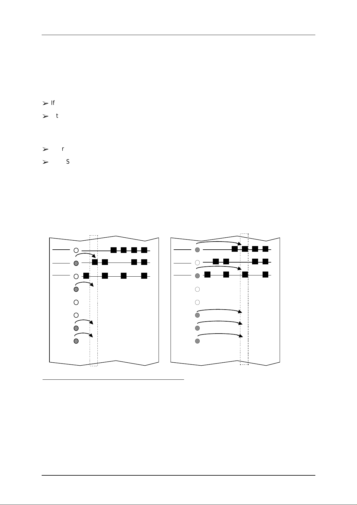
Example 1:
Dis
showing that slaves with
addresses 5, 6 and 9 are active.
SF
APF
CER
AUP
CM
Figure 2-6 Display of the Active AS-i Slaves on the CP Front Panel
4 9 14 19 24 29
3 8 13 18 23 28
2 7 12 17 22 27
1 6 11 16 21 26 31
0 5 10 15 20 25 30
Exam
Dis
addresses 20, 21 and 22 are active.
SF
APF
CER
AUP
CM
le 2:
showing that slaves with
4 9 14 19 24 29
3 8 13 18 23 28
2 7 12 17 22 27
1 6 11 16 21 26 31
0 5 10 15 20 25 30
2-8
Page 20

B8976111/02 AS-i Master Module CP 142-2
2.1.4.4 Meaning of theSET/DISPLAY Button
The SET/DISPLAY button is used to change to the next display and to switch between the
configuration mode and the protected mode.
±
Pressing the SET/DISPLAY button briefly (less than 5 seconds) changes the display.
±
Pressing the SET/DISPLAY button for longer than 5 seconds changes the module from the
configuration mode to the protected mode and vice-versa (see 2.1.4.6).
The SET/DISPLAY button is to the left of the AS-i connector and is protected by a screw-on cover.
Access to the button is only possible when the cover is removed. After using the button, make sure
that you replace the cover again, otherwise the degree of protection is not guaranteed. The button is
in a recess to prevent it being pressed accidentally. It can be pressed using a ball-point pen or a
similar thin blunt instrument.
2.1.4.5 Slots Permitted for the CP 142-2 in the ET 200X Distributed I/O Station
The CP 142-2 can be operated in any slot in the ET 200X distributed I/O station.
The number of CP 142-2 modules that can be operated at the same time in the ET 200X distributed
I/O station depends on the basic module being used:
±
With the BM141 and BM142 basic modules, you can operate a maximum of six CP 142-2
modules at the same time.
±
With the basic module BM147, you can operate a maximum of seven CP 142-2 modules at the
same time.
2.1.4.6 Configuring the AS-Interface with the SET/DISPLAY Button
Recognizing the display state
The CP 142-2 distinguishes between two operating modes on the AS-Interface:
±
Configuration mode (“CM” LED lit)
±
Protected mode (“CM” LED not lit)
If you press the SET/DISPLAY button for more than 5 seconds, you trigger a mode change. After
approximately 5 seconds, the three LEDs of the group display start to flash. The mode changes when
you release the button.
2-9
Page 21

B8976111/02 AS-i Master Module CP 142-2
Configuration mode
The configuration mode is used to install and start up an AS-i installation.
In the configuration mode, the CP 142-2 can exchange data with every slave attached to the AS-i
cable (with the exception of a slave with address “0”). Any AS-i slaves that are added later are
activated immediately and included in the cyclic data exchange.
After the system has been installed and tested, the CP 142-2 can be switched to the protected mode
by pressing the SET/DISPLAY button for longer than 5 seconds. At the same time, active AS-i slaves
are configured. The following data are then stored permanently on the CP 142-2:
±
The addresses of the AS-i slaves
±
The ID codes
±
The I/O configuration
±
The current slave parameters
Protected mode
In the protected mode, the CP 142-2 exchanges data with the configured AS-i slaves. “Configured”
means that the slave addresses stored on the CP 142-2 and the configuration data stored on the CP
142-2 match the values of the existing AS-i slaves.
Steps in configuration
1. Change the CP 142-2 to the “Status Display” mode with the SET/DISPLAY (press the
SET/DISPLAY briefly, all group LEDs go off).
2. Check that the CP 142-2 is in the “Configuration Mode” state (“CM” LED lit). If the CP
142-2 is not in the configuration mode, press the SET/DISPLAY button for longer than 5
seconds until the LEDs of the group display flash.
3. Switch to the slave display by pressing the SET/DISPLAY button briefly to check whether
all the slaves connected to the AS-Interface are indicated.
4. Configure the CP 142-2 by pressing the SET/DISPLAY button for more than 5 seconds
(the LEDs of the group display flash). At the same time, the CP 142-2 is switched to the
protected mode. The “CM” LED goes off.
The “CER” LED also goes off since following configuration, the “expected configuration”
stored on the CP 142-2 matches the stored “actual configuration” on the AS-Interface.
2-10
Page 22

B8976111/02 AS-i Master Module CP 142-2
Configuring the CP 142-2 during an AS-i Power Fail (for example when the AS-i power
supply unit is turned off or when the CP 142-2 is not connected to the AS-Interface)
resets the configuration of the CP 142-2. This means the following:
•
No AS-i slaves are configured
•
All AS-i slave parameters are set
•
Automatic address programming is activated
Changing from the configuration mode to the protected mode is only possible when
there is no slave with address “0” connected to the AS-Interface. If a slave “0” is
connected, the “SF” LED lights up when you press the SET/DISPLAY button.
2.1.4.7 Types of Operation with the CP 142-2
With the CP 142-2 module, two types of operation are possible:
•
Standard operation
• •
Extended operation (with FC “ASI_3422”)
The difference between the two types of operation is as follows:
Standard operation
In this type of operation, the CP 142-2 behaves like a conventional analog input/output module. Four
input and four output bits are reserved in the controller for each slave on the AS-i cable.
In standard operation, no commands or special parameters can be transferred to the slaves on the
AS-i cable. This type of operation corresponds to the profile M0 of the AS-i master specification.
Extended operation (with FC “ASI_3422”)
With this type of operation, the entire range of functions in the AS-i system are available to the PLC
programmer. In particular, the AS-i master calls (for example to assign parameters to slaves) are
available. This type of operation corresponds to profile M1 of the AS-i master specification.
For extended operation, the “ASI_3422” FC is also required in addition to the CP 142-2. This FC is
shipped with this manual.
Please note that extended operation is currently only possible with the BM147.
2-11
Page 23

B8976111/02 AS-i Master Module CP 142-2
3 Standard Operation of the CP 142-2
Standard operation with the CP 142-2 in the ET 200X distributed I/O station is the most common and
simplest application of the CP 142-2. It allows access to the input and output data of the AS-i slaves.
This type of operation corresponds to the M0 profile of the AS-i master specification and is available
immediately after plugging in the module. No extra FC is required.
3.1 Addressing the CP 142-2
From the point of view of the user program, how the CP 142-2 is addressed depends mainly on the
basic module you are using.
3.1.1 Addressing using the BM141/BM142
From the point of view of the PROFIBUS DP master, the CP 142-2 occupies 16 input bytes and 16
output bytes. How these bytes are addressed depends on the PROFIBUS-DP master you are using
and the configuration tool.
For more detailed information, refer to /4/ and the manuals for your PROFIBUS-DP master.
3.1.2 Addressing when using the BM147
The CP 142-2 occupies 16 input bytes and 16 output bytes in the area of the analog I/Os of the
BM147.
The start address of this address area is decided by the slot of the CP 142-2.
Module Basic module CP CP CP CP CP CP CP
Slot number 1 2 3 4 5 6 7 8 9 10
Start addresses - 256 272 288 304 320 336 352
3-1
Page 24

B8976111/02 AS-i Master Module CP 142-2
3.2 How the User Program Addresses the AS-i Slaves
3.2.1 Addressing AS-i User Data
Each slave on the AS-i cable is assigned four bits (a nibble) of input data and four bits of output data
by the CP 142-2. This nibble can be written (slave output data) and read (slave input data). This
allows bi-directional slaves to be accessed.
In total, the maximum of 31 AS-i slaves occupy 16 bytes of input data and 16 bytes of output data
(see table below).
±
When using the CP with the BM141/BM142, the start addresses m and n of the input or output
data depend on the configuration of the PROFIBUS DP master.
±
When using the CP with the BM147, the start addresses depend on the slot of the CP (see
Section 3.1.2). The values m and n are then always the same.
Assignment of the input data of the slaves
Byte Number Bits 7-4 Bits 3-0
m+0 Reserved for FC “ASI_3422” Slave 1
m+1 Slave 2 Slave 3
m+2 Slave 4 Slave 5
m+3 Slave 6 Slave 7
m+4 Slave 8 Slave 9
m+5 Slave 10 Slave 11
m+6 Slave 12 Slave 13
m+7 Slave 14 Slave 15
m+8 Slave 16 Slave 17
m+9 Slave 18 Slave 19
m+10 Slave 20 Slave 21
m+11 Slave 22 Slave 23
m+12 Slave 24 Slave 25
m+13 Slave 26 Slave 27
m+14 Slave 28 Slave 29
m+15 Slave 30
Bit 3 | Bit 2 | Bit 1 | Bit 0
Bit 3 | Bit 2 | Bit 1 | Bit 0
Slave 31
Bit 3 | Bit 2 | Bit 1 | Bit 0
m = start address of the input data
3-2
Page 25

B8976111/02 AS-i Master Module CP 142-2
Assignment of the output data of the slaves
Byte Number Bit 7-4 Bit 3-0
n+0 reserved Slave 1
Bit 3 | Bit 2 | Bit 1 | Bit 0
n+1 Slave 2 Slave 3
n+2 Slave 4 Slave 5
n+3 Slave 6 Slave 7
n+4 Slave 8 Slave 9
n+5 Slave 10 Slave 11
n+6 Slave 12 Slave 13
n+7 Slave 14 Slave 15
n+8 Slave 16 Slave 17
n+9 Slave 18 Slave 19
n+10 Slave 20 Slave 21
n+11 Slave 22 Slave 23
n+12 Slave 24 Slave 25
n+13 Slave 26 Slave 27
n+14 Slave 28 Slave 29
n+15 Slave 30
Bit 3 | Bit 2 | Bit 1 | Bit 0
Slave 31
Bit 3 | Bit 2 | Bit 1 | Bit 0
n = start address of the output data
The first four input bits (first ni bble) are reserved for using FC “ASI_3422”. If no FC is
used, these bits change approximately every 2.5 seconds between the values 8
The first four output bits (first nibble) have no effect on the CP 142-2.
and EH.
H
3-3
Page 26
B8976111/02 AS-i Master Module CP 142-2
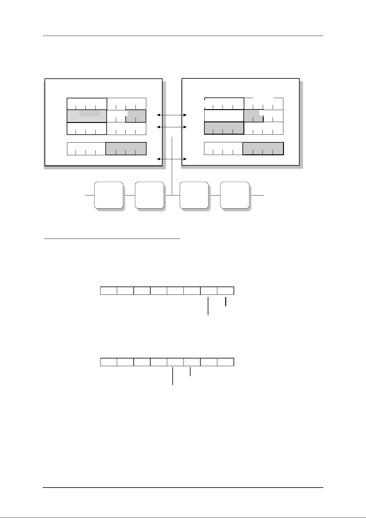
Figure 3-1 shows an example of how a slave is addressed by a user program with start addresses m
= 256 for the input data and n = 256 for the output data. The bits relevant for the user program are
shown on a gray background. The bits on a white background are irrelevant for the user program.
Input
b yte
reserved
256
257
Bit 3
258
.
.
.
Bit 3
271
765
Slave 2
Slave 4
Slave 30
Slave 1
Slave 3
Bit 0Bit 1Bit 2
Slave 5
Bit 0Bit 1Bit 2Bit 3
Slave 31
Slave
31
Bit 0Bit 1Bit 2
4
3210
Bit 0Bit 1Bit 2Bit 3
Bit 0Bit 1Bit 2Bit 3
Bit 0Bit 1Bit 2Bit 3
Bit 0Bit 1Bit 2Bit 3
Bit 0Bit 1Bit 2Bit 3
Output
byte
256
257
258
.
.
.
271
reserved
Slave 2
Bit 2Bit 3
Slave 30
Bit 2Bit 3
7
Bit 1
Slave 4
Bit 1
6
Bit 0
Bit 0Bit 1Bit 2Bit 3
Bit 0
5
43
Slave 1
Slave 5
Slave
Slave 31
31
2
Slave 3
10
Bit 0Bit 1Bit 2Bit 3
Bit 0Bit 1Bit 2Bit 3
Bit 0Bit 1Bit 2Bit 3
Bit 0Bit 1Bit 2Bit 3
Bit 0Bit 1Bit 2Bit 3
AS-i slaves
Slave No. 2 Slave No. 3 Slave No. 4
4I module
2I/2O module
4O module
Slave No.31
4I/4O module
Figure 3-1 Mapping the Slave Addresses on the I/O Addresses
In the diagram above, the 2I/2O module (two inputs and two outputs) occupies bits 0 and 1 in input
byte 257 and bits 2 and 3 in output byte 257. The assignment of the AS-i connections of the bus
modules to the data bits of the input/output bytes is shown below taking slave no. 3 as an example:
1 0 Bit no.
Input byte 257
Connector 1 on the AS-i bus
module
Connector 2 on the AS-i bus module
3 2 Bit no.
Output byte 257
Connector 3 on the AS-i bus module
Connector 4 on the AS-i bus module
3.2.2 Accessing the AS-i User Data (BM141, BM142)
Access to the AS-i user data depends on the PROFIBUS master you are using. For further
information, refer to /4/.
3-4
Page 27

B8976111/02 AS-i Master Module CP 142-2
3.2.3 Access to the AS-i User Data (BM147)
The bits of the AS-i slaves are accessed using the following S7 load and transfer commands:
L PIW X
L PID X
T PQW X
T PQD X
X stands for the byte address in the CP 142-2.
The system restricts access to word or double-word access to even byte addresses. The
byte transfer commands L PIB X or T PQB X are not permitted with the CP 142-2.
Example: Correct:
Incorrect:
Incorrect:
If you want to access individual bits of the slave data, you can use the method shown in the following
sample program for a CP with start address 256:
OPEN DB 20 //open a data block
//
// 1.) at program start: - read in “pseudo PII” of inputs
// (copy the input data
// of the CP 142-2 in
// to a data block)
L PID 256
T DBD 0
L PID 260
T DBD 4
L PID 264
T DBD 8
L PID 268
T DBD 12
.
//
// 2.) In program: - Evaluate individual “input bits””
// - set/reset individual
// “output bits”
A DBX 5.4
S DBX 22.3
R DBX 28.0
.
.
// 3.) At end of program: - output pseudo PIQ of the outputs
// (copy data words to the
// output data of the CP 142-2)
L DBD 16
T PQD 256
L DBD 20
T PQD 260
L DBD 24
T PQD 264
L DBD 28
T PQ 268
L PIW 260
T PQB 260
L PIW 257
3-5
Page 28

B8976111/02 AS-i Master Module CP 142-2
3.3 Diagnostics and Reaction to Interrupts on the CP 142-2
If the CP 142-2 detects an error during operation (AS-i slave failed, EEPROM fault on the CP, ...), it
indicates this by triggering a diagnostic interrupt. The reaction to this diagnostic interrupt depends on
the basic module being used.
3.3.1 Diagnostics and Reaction to Interrupts with the BM141/BM142
The basic module BM141/ BM 142 signals this diagnostic interrupt in PROFIBUS-DP with slave
diagnostics complying with the standard EN 50170 Part 2. The diagnostic frame sent by the ET 200X
distributed I/O system is described in /4/. In particular, the ET 200X signals the “data record 1”
supplied by the CP 142-2 in “device-specific diagnostics”. The CP 142-2 indicates the cause of the
diagnostic interrupt, for example the failure of an AS-i slave in data record 1.
When using the CP 142-2 in the basic module of the ET 200X, remember that the diagnostic
interrupts must be enabled (refer to the configuration tool you are using).
The reaction to the ET 200X diagnostic information depends on the PROFIBUS-DP master you are
using and how you react in the application program. For more detailed information about
programming, refer to the documentation of your PROFIBUS-DP master.
3.3.1.1 Interrupt Events
The following events can lead to a diagnostic interrupt being triggered by the CP 142-2:
±
All changes to the AS-i slave configuration in the protected mode
±
AS-i Power Fail in the protected mode
±
EEPROM Error
3-6
Page 29

B8976111/02 AS-i Master Module CP 142-2
3.3.1.2 Structure of PROFIBUS DP Slave Diagnostics
When a diagnostic interrupt is triggered on the CP 142-2, the BM 141/BM 142 reports PROFIBUS DP
slave diagnostic information with the following structure (for more detailed information, refer to /4/):
Byte 0
Byte 1
Byte 2
Station status 1 to 3
Byte 3
Byte 4
Byte 5
Byte 6
Byte 7
Byte 8
Byte 9
Byte 10
Byte 11
Byte 12
Byte 13
Byte 14
Byte 15
Byte 16
Byte 17
Byte 18
Byte 19
Byte 20
Byte 21
Byte 22
Byte 23
Master PROFIBUS address
High byte Vendor
Low byte ID
ID-related diagnostics
14
: Length of the device-related diagnostics
H
01
: Code for S7 diagnostic interrupt
H
Slot of the module with diagnostic information
00
: reserved
H
Device-related diagnostic information
Data record 1
see Figure 3-3
00
Byte 24
: not used
H
Byte 25
Byte 26
Byte 27
00
Byte 28
Figure 3-2 Structure of the DP Slave Diagnostic Information
To support special masters, the BM 141/BM 142 can also be configur ed so that t he slave
: not used
H
diagnostic information only includes bytes 0 to 15. Refer to the information in /4/.
In a slave diagnostic message, the slot of the module that caused the diagnostic
message is indicated in bytes 7 and 8 (by setting a bit) as well as in byte 11 (slot
number). Slot 5 is the first slot beside the basic module.
3-7
Page 30

B8976111/02 AS-i Master Module CP 142-2
Content of Data Record 1
The diagnostic information of the CP 142-2 is contained in data record 1. The data record is updated
by the CP 142-2 whenever an interrupt event occurs and is made available to the ET 200X distributed
I/O system.
Data record 1 contains a delta list that includes all the slaves that deviate from the configuration, in
other words, missing, incorrect or not configured (but existing) slaves (each slave is assigned one bit
in the delta list: 0 = no error; 1 = error).
On the CP 142-2, data record 1 has a length of 11 bytes and is structured as follows (the byte
numbering relates to the structure of the DP slave diagnostic information in Figure 3-3a and Figure
3.3b. The following applies to the error bits specified in data record 1: 0 = no error; 1 = error.):
Byte 13
Byte 14
Byte 15
7
0 0
0
Voltage on AS-i cable too low
7
7
0 0 0 0
0
0 Bit no.
Group error bit
Internal CP error
(e.g. EEPROM defective)
External CP error
(e.g. slave failed or APF)
At least 1 slave deviates from expected configuration
0
1C
: Module class
H
0
At least 1 slave deviates from
expected configuration
0: CP normal status
1: Offline
Hardware fault on CP (internal watchdog)
7
Byte 16
Figure 3-3a: Content of Data Record Bytes 13 to 16
0 0 0 0 0 0
0
EEPROM of CP 142-2 defective
0
3-8
Page 31

B8976111/02 AS-i Master Module CP 142-2
Byte 17
Byte 18
Byte 19
Byte 20
Byte 21
Byte 22
Byte 23
7
60
H
00
H
20
H
7
0 Bit no.
0
Slave 7 Slave 0
7
0
Slave 15 Slave 8
7
0
Slave 23 Slave 16
7
0
Fixed value
Delta list
Slave 31 Slave 24
Figure 3-3b: Content of Data Record Bytes 17 to 23
3-9
Page 32

B8976111/02 AS-i Master Module CP 142-2
3.3.2 Diagnostics and Reaction to Interrupts with the BM147
3.3.2.1 Overview
If the CP 142-2 detects an error during operation (AS-i slave failed, EEPROM fault on the CP, ...), it
indicates this by triggering a diagnostic interrupt.
The BM147 then interrupts the cyclic user program (OB1) enters the event as “module fault” in the
system diagnostic buffer and then behaves as follows:
If the user has not programmed the corresponding interrupt OB (OB82), the BM147
±
±
changes to STOP.
±
If the user has programmed OB82, this is started by the PLC operating system. The local data
of OB82 provide the user with certain diagnostic information (which module triggered the
interrupt and what type of error occurred ...). More detailed diagnostic information (which slave
has failed ...) is available to the application program if it reads diagnostic data record DS 1 using
the system function SFC59 (“RD_REC”). Once OB82 has been executed, the BM147 continues
the cyclic program (OB1) starting at the point at which it was interrupted.
3.3.2.2 Interrupt Events
The CP 142-2 distinguishes between interrupt events entering and leaving the state. If the occurrence
of an interrupt event leads to an error-free state (AS-i-CONFIG_OK=TRUE no internal CP error), a
diagnostic interrupt leaving the state is triggered (in OB82: Bit OB82_MDL_DEFECT = 0). All other
interrupt events result in a diagnostic interrupt entering the state (Bit OB82_MDL_DEFECT = 1).
The following events can lead to a diagnostic interrupt being triggered by the CP 142-2:
±
All changes to the AS-i slave configuration in the protected mode
±
AS-i Power Fail in the protected mode
±
EEPROM error
3-10
Page 33

B8976111/02 AS-i Master Module CP 142-2
3.3.2.3 Sequence of Diagnostic Interrupt Servicing
If the CP 142-2 detects an interrupt event, it triggers a diagnostic interrupt. The BM147 checks the
source of the interrupt and reads data record 0 from the CP. Following this, it interrupts the cyclic
user program and behaves as follows:
±
If OB82 is not programmed, the BM147/CPU changes to STOP (default setting).
±
If OB82 is programmed, it is started. Data record 0 is available in the local data bytes 8 to
11 of the local data area of OB82. Data record 1 containing the delta list can (but does
not need to be) read in OB82 using an SFC call (SFC59 “RD_REC”). On completion of
OB82, the BM147 acknowledges the diagnostic interrupt on the CP 142-2.
If interrupt events occur in a state in which this cannot be signaled by triggering a diagnostic interrupt
(for example when BM147 is in the STOP mode or when an older diagnostic interrupt has not yet
been acknowledged), the CP 142-2 behaves as follows:
±
A diagnostic interrupt can be triggered again and when the current entire CP
configuration (in other words AS-i slave configuration and internal CP state relevant to
the interrupt) is not the same as the configuration signaled previously with the diagnostic
interrupt, a diagnostic interrupt with current configuration information is signaled.
±
If triggering of a diagnostic interrupt becomes possible again and if the current entire CP
configuration is the same as the configuration signaled previously by the diagnostic
interrupt, no diagnostic interrupt is signaled. This means that brief slave failures (for
example caused by a faulty contact) may not be indicated in some circumstances.
3.3.2.4 Response to Interrupts in Various CP States
The CP 142-2 generates diagnostic interrupts only in the protected mode and not in the configuration
mode. (Exception: internal hardware fault, for example EEPROM defective)
When the BM147 changes to STOP, the interrupt history is reset, in other words bit
OB82_MDL_DEFECT and all other error bits in data record 0 are reset.
When the module changes from the protected mode to the configuration mode, the interrupt history is
also reset. If the CP changes from the configuration mode to the protected mode and if a
configuration error exists at this time, this is indicated by a diagnostic interrupt. If the signaling of a
diagnostic interrupt is temporarily not possible (for example because the PLC is in the STOP mode),
a diagnostic interrupt is only generated at the next possible point in time when the error still exists.
3-11
Page 34

B8976111/02 AS-i Master Module CP 142-2
3.3.2.5 Local Data of the Diagnostic Organization Block (OB82)
The following table lists data record 0 as it is available in the local data of OB82 (local byte 8 to local
byte 11). For the meaning of the other OB82 local data, please refer to the STEP 7 descriptions.
Byte Bit Variable Name Data type Meaning
8
8
8
8
8
0
OB82_MDL_DEFECT BOOL Group error bit (0: leaving state, 1: entering
2
state)
1
OB82_INT_FAULT BOOL Internal CP error (for example EEPROM
2
defective)
2
OB82_EXT_FAULT BOOL External CP error (for example slave failed or
2
APF)
3
OB82_PNT_INFO BOOL At least one slave differs from the expected
2
configuration
4
OB82_EXT_VOLTAGE BOOL Voltage too low on the AS-Interface (APF)
2
5
8
8
8
OB82_FLD_CONNCTR BOOL always 0 for the CP 142-2
2
6
OB82_NO_CONFIG BOOL always 0 for the CP 142-2
2
7
OB82_CONFIG_ERR BOOL always 0 for the CP 142-2
2
9 OB82_MDL_TYPE BYTE Module class (for the CP 142-2: 1C hex)
0
10
OB82_SUB_NDL_ERR BOOL At least one slave differs from the expected
2
configuration
10
10
1
OB82_COMM_FAULT BOOL always 0 for the CP 142-2
2
2
OB82_MDL_STOP BOOL 0: CP 142-2 is in the normal state, 1: CP 142-
2
2 is in the offline state
10
3
OB82_WTCH_DOG_FLT BOOL Hardware error on the CP (internal
2
watchdog)
10
10
10
10
4
OB82_INT_PS_FLT BOOL always 0 for the CP 142-2
2
5
OB82_PRIM_BATT_FLT BOOL always 0 for the CP 142-2
2
5
OB82_BCKUP_BATT_FLT BOOL always 0 for the CP 142-2
2
7
OB82_RESERVED_2 BOOL always 0 for the CP 142-2
2
11
11
11
11
11
11
0
OB82_RACK_FLT BOOL always 0 for the CP 142-2
2
1
OB82_PROC_FLT BOOL always 0 for the CP 142-2
2
2
OB82_EPROM_FLT BOOL EEPROM of the CP 142-2 defective
2
3
OB82_RAM_FLT BOOL always 0 for the CP 142-2
2
4
OB82_ADU_FLT BOOL always 0 for the CP 142-2
2
5
OB82_FUSE_FLT BOOL always 0 for the CP 142-2
2
3-12
Page 35

B8976111/02 AS-i Master Module CP 142-2
Byte Bit Variable Name Data type Meaning
6
11
11
OB82_HW_INTR_FLT BOOL always 0 for the CP 142-2
2
7
OB82_RESERVED_3 BOOL always 0 for the CP 142-2
2
3.3.2.6 Reading the Diagnostic Data Record DS1
The CP 142-2 continuously updates a delta list containing all the slaves that deviate from the
configuration, in other words, missing, incorrect or not configured (but existing) slaves (each slave is
assigned one bit in the delta list: 0 = no error; 1 = error). This delta list is part of the diagnostic data
record DS1 and you can read it out by calling the operating system function SFC59 (“RD_REC”) in
the interrupt OB (OB82) or at any time in the cyclic program (OB1).
For the CP 142-2, data record DS 1 always has a length of 11 bytes and is structured as follows:
Bytes 0 to 3: These four bytes contain DS0 and correspond to the local data bytes 8 to 11 in
OB82 (see Section 3.3.2.5)
Byte 4
Byte 5
Byte 6
Byte 7
Byte 8
Byte 9
Byte 10
7
60
H
00
H
20
H
7
0 Bit no.
0
Slave 7 Slave 0
7
0
Slave 15 Slave 8
7
0
Slave 23 Slave 16
7
0
Fixed value
Delta list
Slave 31 Slave 24
Figure 3-4: Content of Data Record 1 Bytes 4 to 10
3-13
Page 36

B8976111/02 AS-i Master Module CP 142-2
3.3.2.7 Programming Example
The example below illustrates how you can react to a diagnostic interrupt from the CP 142-2 in OB82
by reading the data record (DS1).
.
.
.
L #OB82_MDL_ADDR //module address supplied by OB82
T MW 98 //store temporarily
CALL „RD_REC”
REQ :=TRUE
IOID :=B#16#54
LADDR :=MW98 //stored module address
RECNUM :=B#16#1 //DS1
RET VAL :=MW96 //status/error info
BUSY :=M90.0 //irrelevant for ET200X
RECORD :=P#M 100.0 BYTE 11 //receive buffer
.
.
.
AM100.7 //error on AS-i slave 7
CCFC21 //error reaction
.
.
.
How the program functions
It is assumed that slaves 1 and 12 were configured using the buttons on the CP 142-2 and that the
CP 142-2 is in the protected mode.
If slave 7 fails, the CP 142-2 generates a diagnostic interrupt. The BM147 then enters the message
“module fault” in the system diagnostic buffer and starts OB82 (program above). On completion of
OB82, the delta list contains the following information:
MB 107 80
MB 108 00
MB 109 00
MB 110 00
H
H
H
H
3-14
Page 37

B8976111/02 AS-i Master Module CP 142-2
If the unconfigured slave 15 is then attached to the AS-Interface, the CP 142-2 once again generates
a diagnostic interrupt. The message “module fault” appears in the diagnostic buffer. The delta list
changes to the values below:
MB 107 80
MB 108 80
MB 109 00
MB 110 00
H
H
H
H
After attaching slave 7 to the AS-Interface again, there is still a problem (slave 15). The message
“module fault” appears in the system diagnostic buffer and the delta list has the following values:
MB 107 00
MB 108 80
MB 109 00
MB 110 00
H
H
H
H
After disconnecting slave 15, there is no further problem. The CP 142-2 signals this with a diagnostic
interrupt. The message “module OK” appears in the diagnostic buffer and the delta list is empty:
MB 107 00
MB 108 00
MB 109 00
MB 110 00
H
H
H
H
3-15
Page 38

B8976111/02 AS-i Master Module CP 142-2
4 CP 142-2 Extended Operation with FC “ASI_3422”
For extended operation, FC “ASI_3422” is required on the S7 programmable controller. This section
explains the range of functions available over and above those of standard operation when using the
CP 142-2 with the FC “ASI_3422”.
Extended operation allows the complete control of a master from the user program. Access to the
inputs and outputs is the same as in standard operation with the CP 142-2. In extended operation, a
special FC is used in the user program for communication with the AS-i master CP.
It is only possible to use FC “ASI_3422” in conjunction with a BM147.
The FC used is the same block as used with the CP 342-2.
4.1 Overview of the Functions
Command calls to the CP 142-2 are made in the user program using FC “ASI_3422”. The user
specifies the command call in a send buffer and starts the job. FC “ASI_3422” transfers the command
to the CP 142-2. On completion of the job, the job status is transferred to the user and any response
data are available in a receive buffer.
4.1.1 Calling the Function
The function must be called cyclically for each available CP 142-2. At any one time, only one job can
be processed per CP 142-2. An active job cannot be interrupted by the user and the function does
not include watchdog timing.
STL representation CALL ASI_3422 ( ACT:=
STARTUP:=
LADDR:=
SEND:=
RECV:=
DONE:=
ERROR:=
STATUS:= );
4-1
Page 39

B8976111/02 AS-i Master Module CP 142-2
LAD representation
EN
ACT
STARTUP
LADDR
SEND
RECV
STATUS
ASI_3422
ENO
DONE
ERROR
4-2
Page 40

B8976111/02 AS-i Master Module CP 142-2
Formal parameters
The following table explains the formal parameters of the function:
Name I/O Type Memory
Area
ACT I BOOL I,Q,M,D,L,
constant
Execution of the command by the function is level
triggered, in other words as long as ACT = 1, command
execution is started if no call is already being processed.
STARTUP I BOOL I,Q,M,D,L,
constant
A CPU startup is indicated to the function by STARTUP =
1. After the function has been run for the first time,
STARTUP must be reset by the user.
LADDR I WORD I,Q,M,D,L,
Module start address
constant
The module start address must be determined according
to the rules for slot-oriented address assignment (for
more detailed information refer to Section 3.1).
SEND I ANY I,Q,M,D,L Send buffer
The parameter points to a memory area in which the
command must be specified by the user.
e.g.: P#DB20.DBX 20.0 Byte 10
RECV I ANY I,Q,M,D,L Receive buffer
Remarks
This buffer is only relevant for commands that supply
response data.
The parameter points to a memory area in which the
command response is entered. The length of the data
area assigned here is irrelevant.
e.g.: P#DB30.DBX 20.0 Byte 1
DONE Q BOOL Q,M,D,L DONE = 1 signals “job complete without error”.
ERROR Q BOOL Q,M,D,L ERROR = 1 signals “job completed with error”.
STATUS I/Q DWORD M,D 1st word: Job status / error code (see table below)
If the job was completed with an error, an error code is
generated to provide more detailed information.
2nd word: This is required by the FC internally and must
not
be changed.
4-3
Page 41

B8976111/02 AS-i Master Module CP 142-2
If an error occurs when executing the function, a “0” is entered in the BIE bit in addition to the
information above in ERROR and STATUS. The BIE bit is scanned differently in LAD and STL user
programs:
±
LAD: Query using the ENO output parameter
±
STL: Direct querying of the BIE bit
Status and error information
The following table lists the possible information in the first word of STATUS depending on DONE and
ERROR.
DONE ERROR STATUS Meaning
0 0 8181
1 0 0000
0 1 8090
0 1 80A0
0 1 80A1
0 1 80B0
0 1 80B1
0 1 80C0
0 1 80C1
0 1 80C2
0 1 80C3
0 1 80C4
0 1 8182
0 1 8184
H
Job active
H
Job completed without error
H
Address in LADDR invalid
H
Negative acknowledgment when reading from module
H
Negative acknowledgment when writing to module
H
Module does not recognize the data record
H
Specified data record length incorrect
H
Data record cannot be read
H
The specified data record is currently being processed
H
There is a job bottleneck
H
Resources (memory) in use
H
Communication error
ID after complete restart (STARTUP=TRUE)
H
H
Data type of the RECV formal address incorrect
0 1 8381
0 1 8382
0 1 8383
0 1 8384
0 1 8385
0 1 83A1
0 1 83A2
0 1 83A3
0 1 83A4
H
Slave address incorrect
H
Slave is not activated (not in LAS )
H
Error on the AS-Interface
H
Command not permitted in the current state of the CP
H
Slave 0 exists
H
Slave with address to be modified not found on AS-Interface
H
Slave 0 exists
H
Slave with new address already exists on AS-Interface
H
Slave address cannot be deleted
4-4
Page 42

B8976111/02 AS-i Master Module CP 142-2
DONE ERROR STATUS Meaning
0 1 83A5
0 1 83A6
0 1 83F8
0 1 83F9
0 1 8F22
8F23
0 1 8F24
8F25
0 1 8F28
8F29
H
Slave address cannot be set
H
Slave address cannot be permanently stored
H
Job number unknown
H
EEPROM error
H
Area length error reading a parameter
H
Area length error writing a parameter
This error code indicates that a parameter is completely or partly
outside the address range or the length of a bit field of an ANY
parameter cannot be divided by 8.
H
Area error reading a parameter
H
Area error writing a parameter
This error code indicates that a parameter is in an area that is not
permitted for a system function.
H
Alignment error reading a parameter
H
Alignment error writing a parameter
0 1 8F30
8F31
0 1 8F32
0 1 8F3A
0 1 8F42
8F43
0 1 8F44
8F45
0 1 8F7F
This error code indicates that the reference to a parameter is an
address whose bit address is not 0.
H
The parameter is in the write-protected global DB
H
The parameter is in the write-protected instance DB
This error code indicates that a parameter is in a write-protected
data block.
H
The parameter contains a DB number that is too high
H
The parameter contains the number of a DB that is not loaded
H
An access error occurred when the system attempted to read a
parameter from the peripheral inputs.
An access occurred when the system attempted to write a
H
parameter to the peripheral outputs.
H
This error code indicates that a parameter could not be read
H
This error code indicates that a parameter could not be written
H
Internal error
4-5
Page 43

B8976111/02 AS-i Master Module CP 142-2
Signal changes of the formal operands
A command call is started by ACT = 1. While a job is being processed, the first word of STATUS has
the value 8181
. This indicates that a job is being processed. Once the job is completed, the user is
H
informed of the result in the DONE or ERROR parameters.
If no error occurred, DONE is set. When jobs involve response data from the CP 142-2, these are
entered in the receive buffer specified in the RECV. In this case, 0000
is entered in the first word of
H
STATUS.
If an error occurred, ERROR is set. In this case, no received data are provided by the CP 142-2 even
when the job normally involves response data. To provide a more detailed description of the error, an
error code is entered in the first word of STATUS.
The DONE, ERROR and STATUS parameters remain unchanged until the next job is processed.
ACT
DONE
ERROR
STATUS
8181 0000 0000
8181 8181 8181
8381
Block data
The block length, length of the MC7 code and number of local data bytes used depend on the version
of the function. The current data can be found in the “Block Properties” dialog box in the STEP 7
editor.
Sample programs
The diskette shipped with this manual contains sample programs illustrating the use of FC
“ASI_3422”.
0000
8181
0000
4-6
Page 44

B8976111/02 AS-i Master Module CP 142-2
4.2 Interface for AS-i commands
The following sections describe the AS-i command calls that can be sent by the BM 147 to the
CP 142-2. With these command calls, the CP 142-2 provides the complete functionality of the M1
master profile of the AS-i master specification. In addition to this, the CP 142-2 can be configured
completely by the BM147 using command calls.
4.2.1 The Commands Supported by the CP 142-2
How to use the jobs is explained in the descriptions of the individual jobs, the “AS-Interface
Introduction and Basic Information” manual, the PICS appendix and the detailed explanations in /1/
and /2/.
The commands that can be executed are listed in the following table:
Name / Section Parameter Return Coding:
Set_Permanent_Parameter / 4.2.1.1 Slave address,
parameter
Get_Permanent_Parameter / 4.2.1.2 Slave address Parameter 0 1
Write_parameter / 4.2.1.3 Slave address,
parameter
Parameter echo
(optional)
Read_Parameter / 4.2.1.4 Slave address Parameter value 0 3
Store_Actual_Parameters / 4.2.1.5 none 0 4
Set_Permanent_Configuration / 4.2.1.6 Slave address
configuration
Get_Permanent_Configuration / 4.2.1.7 Slave address Expected configuration
data
Store_Actual_Configuration / 4.2.1.8 none 0 7
Read_Actual_Configuration / 4.2.1.9 Slave address Actual configuration data 0 8
Set_LPS / 4.2.1.10 LPS 0 9
Set_Offline_Mode / 4.2.1.11 Mode 0 A
Set_Auto_Address / 4.2.1.12 Mode 0 B
Set_Operation_Mode / 4.2.1.13 Mode 0 C
Change_Slave_Address / 4.2.1.14 Address1, address2 0 D
Read Slave Status / 4.2.1.15 Slave address Error record of the slave 0 F
Read Lists and Flags / 4.2.1.16 none LDS,LAS,LPS,flags 1 0
Read Total Configuration / 4.2.1.17 Actual configuration data,
actual parameters
LAS, flags
Configure Total System / 4.2.1.18 Total
configuration
Write Parameter List / 4.2.1.19 List of
parameters
Read Parameter Echo List / 4.2.1.20 none Parameter echo list 1 3
Read Version Number / 4.2.1.21 none Version string 1 4
Read and Reset Slave Status / 4.2.1.22 Slave address Error record of the slave 1 6
Read Slave ID / 4.2.1.23 Slave address ID code 1 7
Read Slave I/O / 4.2.1.24 Slave address I/O configuration 1 8
0 0
0 2
0 5
0 6
1 9
1 A
1 C
H
H
H
H
H
H
H
H
H
H
H
H
H
H
H
H
H
H
H
H
H
H
H
H
Table 4-2 Overview of the Command Jobs
4-7
Page 45

B8976111/02 AS-i Master Module CP 142-2
4.2.1.1 Set_Permanent_Parameter
Meaning
With this call, a parameter value for the specified AS-i slave is transferred to the CP 142-2. The value
is saved permanently as a configured value.
The parameter is
not
transferred immediately to the slave by the CP 142-2. The parameter value is
only transferred after the power supply of the BM147 is turned on and the slave is activated.
Structure of the job data in the send buffer
Bit 7 Bit 0
Byte 0 0 H 0 H
Byte 1 Slave address
Byte 2 0 Parameter
4.2.1.2 Get_Permanent_Parameter
Meaning
With this call, a slave-specific parameter value stored on the EEPROM of the CP 142-2 is read.
Structure of the job data in the send buffer
Bit 7 Bit 0
Byte 0 0 H 1 H
Byte 1 Slave address
Structure of the job data in the receive buffer
Bit 7 Bit 0
Byte 0 0 H Parameter
4-8
Page 46

B8976111/02 AS-i Master Module CP 142-2
4.2.1.3 Write_Parameter
Meaning
With this call, a parameter value is transferred and sent directly via the AS-i bus to the addressed AS1 slave. The parameter is saved only temporarily on the CP 142-2.
The AS-i slave transfers the current parameter value in the response. This can deviate from the
values that have just been written according to the AS-i master specification (/2/). The slave response
is entered in the parameter echo field.
The RECEIVE job to “fetch” the parameter echo is optional. Normally, the parameter echo is not
evaluated in the S7 program.
Structure of the job data in the send buffer
Bit 7 Bit 0
Byte 0 0 H 2 H
Byte 1 Slave address
Byte 2 0 Parameter
Structure of the job data in the receive buffer
Bit 7 Bit 0
Byte 0 0 Parameter echo
4.2.1.4 Read_Parameter
Meaning
This call returns the current parameter value (actual parameter) of a slave.
Structure of the job data in the send buffer
Bit 7 Bit 0
Byte 0 0 H 3 H
Byte 1 Slave address
Structure of the job data in the receive buffer
Bit 7 Bit 0
Byte 0 0 Parameter echo
4-9
Page 47

B8976111/02 AS-i Master Module CP 142-2
4.2.1.5 Store_Actual_Parameters
Meaning
This call overwrites the permanently stored configured parameters with the actual parameters, in
other words the parameters of all slaves are reconfigured.
Structure of the job data in the send buffer
Bit 7 Bit 0
Byte 0 0 H 4 H
4.2.1.6 Set_Permanent_Configuration
Meaning
This call configures the I/O configuration data and the ID code for the addressed AS-i slave. The data
are stored permanently on the AS-i master CP.
When executing this command, the CP changes to the offline phase and then switches
to the normal mode (cold restart on the CP).
The call is not executed in the protected mode.
Structure of the job data in the send buffer
Bit 7 Bit 0
Byte 0 0 H 5 H
Byte 1 Slave address
Byte 2 ID code I/O configuration
4-10
Page 48

B8976111/02 AS-i Master Module CP 142-2
4.2.1.7 Get_Permanent_Configuration
Meaning
This call returns the desired configuration data of an addressed slave stored permanently in the
EEPROM (I/O configuration data and the ID codes).
Structure of the job data in the send buffer
Bit 7 Bit 0
Byte 0 0 H 6 H
Byte 1 Slave address
Structure of the job data in the receive buffer
Bit 7 Bit 0
Byte 0 ID code I/O configuration
4.2.1.8 Store_Actual_Parameters
Meaning
This call stores the actual I/O configuration data and actual ID codes of all slaves on the AS-Interface
permanently on the EEPROM as desired configuration data. The list of activated slaves (LAS) is also
entered in the list of configured slave (LPS).
When executing this command, the CP changes to the offline phase and then switches
to the normal mode (cold restart on the CP).
The call is not executed in the protected mode.
Structure of the job data in the send buffer
Bit 7 Bit 0
Byte 0 0 H 7 H
4-11
Page 49

B8976111/02 AS-i Master Module CP 142-2
4.2.1.9 Read_Actual_Configuration
This call returns the actual I/O configuration data and actual ID codes of an addressed slave detected
on the AS-i.
Structure of the job data in the send buffer
Bit 7 Bit 0
Byte 0 0 H 8 H
Byte 1 Slave address
Structure of the job data in the receive buffer
Bit 7 Bit 0
Byte 0 ID code I/O configuration
4.2.1.10 Set_LPS
Meaning
With this call, the list of configured slaves is transferred for permanent storage in the EEPROM of the
master.
When executing this command, the CP changes to the offline phase and then switches
to the normal mode (cold restart on the CP).
The call is not executed in the protected mode.
Structure of the job data in the send buffer
Bit 7 Bit 0
Byte 0 0 H 9 H
Byte 1 0 H 0 H
Byte 2 LPS slave 0..3
0 | 1 | 2 | 3
Byte 3 LPS slave 8 to 11
8 | 9 | 10 | 11
Byte 4 LPS slave 16 to 19
16 | 17 | 18 | 19
Byte 5 LPS slave 24 to 27
24 | 25 | 26 | 27
In the LPS data, 0 means slave not configured and 1 means slave configured.
LPS slave 4 to 7
4 | 5 | 6 | 7
LPS slave 12 to 15
12 | 13 | 14 | 15
LPS slave 20 to 23
20 | 21 | 22 | 23
LPS slave 28 to 31
28 | 29 | 30 | 31
4-12
Page 50

B8976111/02 AS-i Master Module CP 142-2
4.2.1.11 Set_Offline_Mode
Meaning
This call switches between the online and offline mode.
The OFFLINE bit is
not
permanently stored, in other words, during the startup/restart the bit is set to
ONLINE again.
In the offline mode, the CP only processes jobs from the user. There is no cyclic data exchange.
online mode
The
is the normal situation with the AS-i master. Here, the following jobs are processed
cyclically:
±
During the data exchange phase, the fields of the output data are transferred to the slave
outputs for all slaves in the LAS. The addressed slaves transfer the values of the slave
inputs to the master when the transfer was free of errors.
±
This is followed by the inclusion phase in which there is a search for the slaves
connected to the AS-i and newly added slaves are entered in the LDS or LAS.
±
In the management phase, jobs from the user such as writing parameters are executed.
Structure of the job data in the send buffer
Bit 7 Bit 0
Byte 0 0 H A H
Byte 1 0 H Mode (0=online
1=offline)
4-13
Page 51

B8976111/02 AS-i Master Module CP 142-2
4.2.1.12 Set_Auto_Address
Meaning
With this call, the automatic address programming function can be enabled or disabled.
AUTO_ADDR_ENABLE
The
Structure of the job data in the send buffer
Bit 7 Bit 0
Byte 0 0 H B H
Byte 1 0 H Mode
The change in the AUTO_ADDR_ENABLE bit from 1 to 0 i s effective immedi ately, the
change from 0 to 1 only after the CP 142-2 changes to OFFLINE.
bit is stored permanently on the master.
(1=autoprog enabled
0=autoprog
disabled)
4.2.1.13 Set_Operation_Mode
With this call, you can select between the configuration mode and the protected mode.
protected mode
In the
match are activated, in other words if the I/O configuration and the identification codes of the slaves
in the LDS are identical to those of the configured values.
configuration mode
In the
applies to slaves for which there is a difference between the desired and actual configuration. The
OPERATION MODE bit is saved
startup/warm restart.
When changing from the configuration mode to the protected mode, the CP is restarted (transition to
the offline phase followed by switchover to the online mode).
If the address 0 is entered in the LDS for a slave, the CP cannot switch from the configuration mode
to the protected mode.
Structure of the job data in the send buffer
Bit 7 Bit 0
Byte 0 0 H C H
Byte 1 0 H Mode
, only slaves marked in the LPS and whose desired and actual configuration
, all detected slaves (except slave address “0”) are activated. This also
permanently
(0=protected mode
1=configuration
mode)
in the EEPROM, i.e. it is retained following a
4-14
Page 52

B8976111/02 AS-i Master Module CP 142-2
4.2.1.14 Change_Slave_Address
Meaning
With this call, the slave address can be changed.
This call is mainly used to add a new AS-i slave with the default address 0 to the AS-i system. In this
case, the address is changed from the old slave address (0) to the new slave address.
This change can only be made when the following conditions are fulfilled:
1. A slave with the
2. If the old slave address is not equal to 0, then an AS-i slave with address 0 cannot be
connected at the same time.
3. The
4. No AS-i slave with the
Note:
When changing the slave address, the AS-i slave is not reset , i n other words the output
data of the slave are retained until new data arrive for the new address.
Structure of the job data in the send buffer
Byte 0 0 H D H
Byte 1 Old slave address
Byte 2 New slave address
new slave address
Bit 7 Bit 0
old slave address
must have a valid value.
new slave address
exists.
must already exist.
4-15
Page 53

B8976111/02 AS-i Master Module CP 142-2
4.2.1.15 Read Slave Status
Meaning
With this call, the status register of the addressed slave can be read out.
The flags of the status register have the following significance:
S0 “Address volatile”
This flag is set
- when the internal slave routine for permanent storage of the slave address is
active. This can take up to 15 ms and must not be interrupted by a further
addressing call.
- when the internal slave address comparison recognizes that the
stored address is not the same as the entry in the address register.
S1 “Parity error detected”
This flag is set when the AS-i slave has recognized a parity error in a received
frame since the last “read and reset status” job.
S2 “End bit error detected”
This flag is set when the AS-i slave has recognized an end bit error in a received
frame since the last “read and reset status” job.
S3 “Read error non-volatile memory”
This flag is set when a read error has occurred when reading the non-volatile
memory.
Structure of the job data in the send buffer
Bit 7 Bit 0
Byte 0 0 H F H
Byte 1 Slave address
Structure of the job data in the receive buffer
Bit 7 Bit 0
Byte 0 0 Slave status
S3 | S2 | S1 | S0
4-16
Page 54

B8976111/02 AS-i Master Module CP 142-2
4.2.1.16 Read Lists and Flags
(Get_LPS, Get_LAS, Get_LDS, Get_Flags)
Meaning
With this call, the following entries are read out of the AS-i master CP:
•
The list of permanent slave LPS,
•
the list of active slaves LAS,
•
the list of detected slaves LDS,
•
the flags according to the AS-i specification
Structure of the job data in the send buffer
Bit 7 Bit 0
Byte 0 1 H 0 H
Structure of the job data in the receive buffer
Bit 7 Bit 4 Bit 3 Bit 0
Byte 0 LAS slave 0 to 3 LAS slave 4 to 7
Byte 1 LAS slave 8 to 11 LAS slave 12 to 15
Byte 2 LAS slave 16 to 19 LAS slave 20 to 23
Byte 3 LAS slave 24 to 27 LAS slave 28 to 31
Byte 4 LDS slave 0 to 3 LDS slave 4 to 7
Byte 5 LDS slave 8 to 11 LDS slave 12 to 15
Byte 6 LDS slave 16 to 19 LDS slave 20 to 23
Byte 7 LDS slave 24 to 27 LDS slave 28 to 31
Byte 8 LPS slave 0 to 3 LPS slave 4 to 7
Byte 9 LPS slave 8 to 11 LPS slave 12 to 15
Byte 10 LPS slave 16 to 19 LPS slave 20 to 23
Byte 11 LPS slave 24 to 27 LPS slave 28 to 31
Byte 12 Flag 1
Byte 13 Flag 2
4-17
Page 55

B8976111/02 AS-i Master Module CP 142-2
Flag 1 Flag 2
Name Bit Number Name Bit Number
OFFLINE_READY 8 OFFLINE 0
APF 9 RESERVED 1
NORMAL_MODE 10 EEPROM_OK 2
CONFIG_MODE 11 AUTO_ADDR_ENABLE 3
AUTO_ADDR_AVAIL 12 RESERVED 4
AUTO_ADDR_ASSIGN 13 RESERVED 5
LDS_0 14 RESERVED 6
CONFIG_OK 15 RESERVED 7
Meaning of the flags
OFFLINE_READY The flag is set when the offline phase is active.
APF This flag is set when the voltage on the AS-i cable is too low.
NORMAL_MODE This flag is set when the CP is in the normal mode.
CONFIG_MODE The flag is set in the configuration mode and reset in the protected mode.
AUTO_ADDR_AVAIL This flag is set when the automatic address programming can be executed
(in other words exactly
one
AS-i slave is currently out of operation).
AUTO_ADDR_ASSIGN This flag is set when the automatic address programming is possible (in
other words AUTO_ADDR_ENABLE = 1
and
there is or was no “incorrect”
AS-i slave connected to the AS-i cable).
LDS_0 This flag is set when an AS-i slave exists with address 0.
CONFIG_OK This flag is set when the desired (configured) and actual configuration
match.
OFFLINE This flag is set when the CP is to change to the OFFLINE mode or is
already in this mode.
EEPROM_OK This flag is set when the test of the internal EEPROM did not detect any
errors.
AUTO_ADDR_ENABLE This flag indicates whether the automatic address programming is enabled
or disabled by the user (0=disabled, 1= enabled).
4-18
Page 56

B8976111/02 AS-i Master Module CP 142-2
4.2.1.17 Read Total Configuration
Meaning
With this command, the following data are read from the CP:
±
The list of active slaves (LAS). This indicates which of the connected slaves are activated.
±
The current configuration data of the connected slaves (I/O configuration and ID code).
±
The current parameters of the slaves (actual parameters).
±
The current flags.
This command can, for example, be used to find out the configuration of the slaves connected to the
AS-i cable after installation. The configuration data read in can be modified if required and saved as
the desired configuration on the CP 142-2 using the 'configure entire system' command (see Section
4.2.1.18.
Structure of the job data in the send buffer
Bit 7 Bit 0
Byte 0 1 H 9 H
Structure of the job data in the receive buffer
Bit 7 Bit 4 Bit 3 Bit 0
Byte 0
Byte 1
Byte 2 LAS slave 0 to 3 LAS slave 4 to 7
Byte 3 LAS slave 8 to 11 LAS slave 12 to 15
Byte 4 LAS slave 16 to 19 LAS slave 20 to 23
Byte 5 LAS slave 24 to 27 LAS slave 28 to 31
Byte 6 ID code slave 0 I/O conf. slave 0
Byte 7 ID code slave 1 I/O conf. slave 1
Byte 8 ID code slave 2 I/O conf. slave 2
Byte 9 ID code slave 3 I/O conf. slave 3
Byte 10 ID code slave 4 I/O conf. slave 4
Byte 11 ID code slave 5 I/O conf. slave 5
Byte 12 ID code slave 6 I/O conf. slave 6
Byte 13 ID code slave 7 I/O conf. slave 7
Byte 14 ID code slave 8 I/O conf. slave 8
Byte 15 ID code slave 9 I/O conf. slave 9
Byte 16 ID code slave 10 I/O conf. slave 10
Byte 17 ID code slave 11 I/O conf. slave 11
Byte 18 ID code slave 12 I/O conf. slave 12
Byte 19 ID code slave 13 I/O conf. slave 13
Byte 20 ID code slave 14 I/O conf. slave 14
Byte 21 ID code slave 15 I/O conf. slave 15
Byte 22 ID code slave 16 I/O conf. slave 16
Byte 23 ID code slave 17 I/O conf. slave 17
Byte 24 ID code slave 18 I/O conf. slave 18
4-19
Page 57

B8976111/02 AS-i Master Module CP 142-2
Bit 7 Bit 4 Bit 3 Bit 0
Byte 25 ID code slave 19 I/O conf. slave 19
Byte 26 ID code slave 20 I/O conf. slave 20
Byte 27 ID code slave 21 I/O conf. slave 21
Byte 28 ID code slave 22 I/O conf. slave 22
Byte 29 ID code slave 23 I/O conf. slave 23
Byte 30 ID code slave 24 I/O conf. slave 24
Byte 31 ID code slave 25 I/O conf. slave 25
Byte 32 ID code slave 26 I/O conf. slave 26
Byte 33 ID code slave 27 I/O conf. slave 27
Byte 34 ID code slave 28 I/O conf. slave 28
Byte 35 ID code slave 29 I/O conf. slave 29
Byte 36 ID code slave 30 I/O conf. slave 30
Byte 37 ID code slave 31 I/O conf. Slave 31
Byte 38 Parameter slave 1
Byte 39 Parameter slave 2 Parameter slave 3
Byte 40 Parameter slave 4 Parameter slave 5
Byte 41 Parameter slave 6 Parameter slave 7
Byte 42 Parameter slave 8 Parameter slave 9
Byte 43 Parameter slave 10 Parameter slave 11
Byte 44 Parameter slave 12 Parameter slave 13
Byte 45 Parameter slave 14 Parameter slave 15
Byte 46 Parameter slave 16 Parameter slave 17
Byte 47 Parameter slave 18 Parameter slave 19
Byte 48 Parameter slave 20 Parameter slave 21
Byte 49 Parameter slave 22 Parameter slave 23
Byte 50 Parameter slave 24 Parameter slave 25
Byte 51 Parameter slave 26 Parameter slave 27
Byte 52 Parameter slave 28 Parameter slave 29
Byte 53 Parameter slave 30 Parameter slave 31
Byte 54 Flag 1
Byte 55 Flag 2
Flag 1 Flag 2
Name Bit Number Name Bit Number
OFFLINE_READY 0 OFFLINE 0
APF 1 RESERVED 1
NORMAL_MODE 2 EEPROM_OK 2
CONFIG_MODE 3 AUTO_ADDR_ENABLE 3
AUTO_ADDR_AVAIL 4 RESERVED 4
AUTO_ADDR_ASSIGN 5 RESERVED 5
LDS_0 6 RESERVED 6
CONFIG_OK 7 RESERVED 7
The meaning of the flags is the same as for the Read Lists and Flags job (Get_LPS, Get_LAS,
Get_LDS, Get_Flags), see Section 4.2.1.16.
4-20
Page 58

B8976111/02 AS-i Master Module CP 142-2
4.2.1.18 Configure Total System
Meaning
With this call, the desired total configuration is transferred to the CP 142-2 and
saved on the CP 142-2 as the desired configuration.
This configures the CP 142-2.
The following data are transferred:
±
The list of configured slaves specifying the slaves that can be activated
by the CP 142-2 in the protected mode.
±
The list of configuration data specifying the ID codes and I/O configurations the slaves must
have.
±
The list of parameters saved in non-volatile memory on the CP. This is transferred to the slaves
during the startup of the CP 142-2.
±
The flags that determine the operating mode of the CP 142-2.
The call is not executed in the protected mode.
Structure of the job data in the send buffer
Bit 7 Bit 4 Bit 3 Bit 0
Byte 0 1 H A H
Byte 1
Byte 2 LPS slave 0 to 3 LPS slave 4 to 7
Byte 3 LPS slave 8 to 11 LPS slave 12 to 15
Byte 4 LPS slave 16 to 19 LPS slave 20 to 23
Byte 5 LPS slave 24 to 27 LPS slave 28 to 31
Byte 6 ID code slave 0 I/O conf. slave 0
Byte 7 ID code slave 1 I/O conf. slave 1
Byte 8 ID code slave 2 I/O conf. slave 2
Byte 9 ID code slave 3 I/O conf. slave 3
Byte 10 ID code slave 4 I/O conf. slave 4
Byte 11 ID code slave 5 I/O conf. slave 5
Byte 12 ID code slave 6 I/O conf. slave 6
Byte 13 ID code slave 7 I/O conf. slave 7
Byte 14 ID code slave 8 I/O conf. slave 8
Byte 15 ID code slave 9 I/O conf. slave 9
Byte 16 ID code slave 10 I/O conf. slave 10
Byte 17 ID code slave 11 I/O conf. slave 11
Byte 18 ID code slave 12 I/O conf. slave 12
Byte 19 ID code slave 13 I/O conf. slave 13
Byte 20 ID code slave 14 I/O conf. slave 14
Byte 21 ID code slave 15 I/O conf. slave 15
Byte 22 ID code slave 16 I/O conf. slave 16
Byte 23 ID code slave 17 I/O conf. slave 17
Byte 24 ID code slave 18 I/O conf. slave 18
4-21
Page 59

B8976111/02 AS-i Master Module CP 142-2
Bit 7 Bit 4 Bit 3 Bit 0
Byte 25 ID code slave 19 I/O conf. slave 19
Byte 26 ID code slave 20 I/O conf. slave 20
Byte 27 ID code slave 21 I/O conf. slave 21
Byte 28 ID code slave 22 I/O conf. slave 22
Byte 29 ID code slave 23 I/O conf. slave 23
Byte 30 ID code slave 24 I/O conf. slave 24
Byte 31 ID code slave 25 I/O conf. slave 25
Byte 32 ID code slave 26 I/O conf. slave 26
Byte 33 ID code slave 27 I/O conf. slave 27
Byte 34 ID code slave 28 I/O conf. slave 28
Byte 35 ID code slave 29 I/O conf. slave 29
Byte 36 ID code slave 30 I/O conf. slave 30
Byte 37 ID code slave 31 I/O conf. slave 31
Byte 38 Parameter slave 1
Byte 39 Parameter slave 2 Parameter slave 3
Byte 40 Parameter slave 4 Parameter slave 5
Byte 41 Parameter slave 6 Parameter slave 7
Byte 42 Parameter slave 8 Parameter slave 9
Byte 43 Parameter slave 10 Parameter slave 11
Byte 44 Parameter slave 12 Parameter slave 13
Byte 45 Parameter slave 14 Parameter slave 15
Byte 46 Parameter slave 16 Parameter slave 17
Byte 47 Parameter slave 18 Parameter slave 19
Byte 48 Parameter slave 20 Parameter slave 21
Byte 49 Parameter slave 22 Parameter slave 23
Byte 50 Parameter slave 24 Parameter slave 25
Byte 51 Parameter slave 26 Parameter slave 27
Byte 52 Parameter slave 28 Parameter slave 29
Byte 53 Parameter slave 30 Parameter slave 31
Byte 54 Flag 1
Byte 55 Flag 2
Flag 1 Flag 2
Name Bit Number Name Bit Number
OFFLINE_READY 0 OFFLINE 0
APF 1 RESERVED 1
NORMAL_MODE 2 EEPROM_OK 2
CONFIG_MODE 3 AUTO_ADDR_ENABLE 3
AUTO_ADDR_AVAIL 4 RESERVED 4
AUTO_ADDR_ASSIGN 5 RESERVED 5
LDS_0 6 RESERVED 6
CONFIG_OK 7 RESERVED 7
Modifiable flags whose values change the mode of the CP 142-2 are shaded:
CONFIG_MODE 0 = CP 142-2 starts up in the protected mode after synchronization
1 = CP 142-2 starts up in the configuration mode.
AUTO_ADDR_ENABLE 0 = automatic address programming disabled,
1 = automatic address programming enabled.
4-22
Page 60

B8976111/02 AS-i Master Module CP 142-2
The values of the other flags have no significance for the 'configure entire system' command and
cannot be modified.
4-23
Page 61

B8976111/02 AS-i Master Module CP 142-2
4.2.1.19 Write Parameter List
Meaning
With this command, the parameters for all slaves are transferred to the CP 142-2. The CP 142-2•
transfers
actual parameters
Structure of the job data in the send buffer
Byte 0 1 H C H
Byte 1
Byte 2 Parameter slave 1
Byte 3 Parameter slave 2 Parameter slave 3
Byte 4 Parameter slave 4 Parameter slave 5
Byte 5 Parameter slave 6 Parameter slave 7
Byte 6 Parameter slave 8 Parameter slave 9
Byte 7 Parameter slave 10 Parameter slave 11
Byte 8 Parameter slave 12 Parameter slave 13
Byte 9 Parameter slave 14 Parameter slave 15
Byte 10 Parameter slave 16 Parameter slave 17
Byte 11 Parameter slave 18 Parameter slave 19
Byte 12 Parameter slave 20 Parameter slave 21
Byte 13 Parameter slave 22 Parameter slave 23
Byte 14 Parameter slave 24 Parameter slave 25
Byte 15 Parameter slave 26 Parameter slave 27
Byte 16 Parameter slave 28 Parameter slave 29
Byte 17 Parameter slave 30 Parameter slave 31
the parameters
only
that have changed
.
Bit 7 Bit 4 Bit 3 Bit 0
to the slaves,
that deviate from the current
4-24
Page 62

B8976111/02 AS-i Master Module CP 142-2
4.2.1.20 Read Parameter Echo List
Meaning
When the parameters are transferred to the slave, they return “echo values” as the response. The
read parameter echo list call outputs the echo values of all slaves. The echo values of a slave
originate from the last parameter call output to this slave.
Structure of the job data in the send buffer
Bit 7 Bit 4 Bit 3 Bit 0
Byte 0 1 H 3 H
Structure of the job data in the receive buffer
Bit 7 Bit 4 Bit 3 Bit 0
Byte 0 Par.echo slave 1
Byte 1 Par.echo slave 2 Par.echo slave 3
Byte 2 Par.echo slave 4 Par.echo slave 5
Byte 3 Par.echo slave 6 Par.echo slave 7
Byte 4 Par.echo slave 8 Par.echo slave 9
Byte 5 Par.echo slave 10 Par.echo slave 11
Byte 6 Par.echo slave 12 Par.echo slave 13
Byte 7 Par.echo slave 14 Par.echo slave 15
Byte 8 Par.echo slave 16 Par.echo slave 17
Byte 9 Par.echo slave 18 Par.echo slave 19
Byte 10 Par.echo slave 20 Par.echo slave 21
Byte 11 Par.echo slave 22 Par.echo slave 23
Byte 12 Par.echo slave 24 Par.echo slave 25
Byte 13 Par.echo slave 26 Par.echo slave 27
Byte 14 Par.echo slave 28 Par.echo slave 29
Byte 15 Par.echo slave 30 Par.echo slave 31
4-25
Page 63

B8976111/02 AS-i Master Module CP 142-2
4.2.1.21 Read Version ID
Meaning
With this call, the version ID of the AS-i master software is read out.
Structure of the job data in the send buffer
Bit 7 Bit 4 Bit 3 Bit 0
Byte 0 1 H 4 H
The reply of the CP contains the name and the firmware version number of the CP in the form shown
below:
Structure of the job data in the receive buffer
Bit 7 Bit 4 Bit 3 Bit 0
Byte 0 S
Byte 1 i
Byte 2 e
Byte 3 m
Byte 4 e
Byte 5 n
Byte 6 s
Byte 7
Byte 8 A
Byte 9 G
Byte 10
Byte 11
Byte 12
Byte 13 C
Byte 14 P
Byte 15
Byte 16 1
Byte 17 4
Byte 18 2
Byte 19 Byte 20 2
Byte 21
Byte 22
Byte 23
Byte 24 V
Byte 25
Byte 26 x
Byte 27
Byte 28 y
Byte 29 y
x.yy stands for the current version number.
4-26
Page 64

B8976111/02 AS-i Master Module CP 142-2
4.2.1.22 Read and Reset Slave Status
Meaning
With this call, the status of a slave is read out and at the same time the status register of the slave is
deleted.
The flags of the status register have the following significance:
S0 “Address volatile”
This flag is set
- when the internal slave routine for permanent storage of the slave address is
active. This can take up to 15 ms and must not be interrupted by a further
addressing call.
- when the internal slave address comparison recognizes that the
stored address is not the same as the entry in the address register.
S1 “Parity error detected”
This flag is set when the slave has recognized a parity error in a received frame
since the last “read and reset status” job.
S2 “End bit error detected”
This flag is set when the AS-i slave has recognized an end bit error in a received
frame since the last “read and reset status” job.
S3 “Read error non-volatile memory”
This flag is set when a read error has occurred when reading the non-volatile
memory.
Structure of the job data in the send buffer
Bit 7 Bit 4 Bit 3 Bit 0
Byte 0 1 H 6 H
Byte 1 Slave address
Structure of the job data in the receive buffer
Bit 7 Bit 4 Bit 3 Bit 0
Byte 0 0 H Slave status
4-27
Page 65

B8976111/02 AS-i Master Module CP 142-2
4.2.1.23 Read Slave ID
Meaning
With this call, the ID code of a slave can be read out directly over the AS-i cable. The call is intended
for diagnostic purposes and is not required in the normal master mode.
Structure of the job data in the send buffer
Byte 0 1 H 7 H
Slave address
Structure of the job data in the receive buffer
Bit 7 Bit 4 Bit 3 Bit 0
Byte 0 0 H Slave ID
4.2.1.24 Read Slave I/O
Meaning
With this call, the I/O configuration of a slave can be read out directly over the AS-i cable. The call is
intended for diagnostic purposes and is not required in the normal master mode.
Structure of the job data in the send buffer
Bit 7 Bit 4 Bit 3 Bit 0
Byte 0 1 H 8 H
Slave address
Structure of the job data in the receive buffer
Bit 7 Bit 4 Bit 3 Bit 0
Byte 0 0 H Slave I/O
4-28
Page 66

B8976111/02 AS-i Master Module CP 142-2
5 Replacing a Defective Slave /
Automatic Address Programming
If the indicator AUP is lit in the protected mode, it indicates the following:
²
Exactly
²
Automatic address programming by the CP 142-2 is possible.
You can now replace the defective AS-i slave as follows:
Remove the failed AS-i slave from the AS-i cable. You can identify the failed AS-i slave simply
by the flashing LED assigned to the AS-i slave when the group display is active (see
Section2.1.4
Replace the defective AS-i slave with an identical AS-i slave with address 0 ( as supplied). The
CP 142-2 then programs this AS-i slave with the address of the original station that had failed.
The “AUP” LED goes off. The CP 142-2 indicates the new AS-i slave in the LED display.
Note that “automatic address programming” is only possible in the following situations:
the “AUTO_ADDR_ENABLE”=1 flag is set (see Section 4.2.1.12)
±
The CP 242-2 is in the protected mode.
±
±
Only
one
AS-i slave has failed.
one As-i slave has failed.
5-1
Page 67

B8976111/02 AS-i Master Module CP 142-2
6 Error Indicators on the CP 142-2 / Dealing with Errors
The following table lists the possible causes of errors that can occur when operating the CP 142-2
and how to remedy the problem.
Error Possible Cause Remedy
APF indicator lit. The AS-i power supply unit is not
connected or is defective.
Power requirements of the AS-i
slave too high.
Result: Voltage on the AS-i cable
too low
Short circuit on the AS-i cable Check the AS-i cable and the connected
SF lights up without pressing the
button.
SF is lit when the SET button is
pressed.
CER LED is permanently lit. The CP 142-2 has not yet been
CER display flickers, in other
words a configured AS-i slave is
lost sporadically.
The CP does not switch from the
configuration mode to the
protected mode.
The CP 142-2 is in the protected
mode and an AS-i configuration
error has occurred (for example
slave failure).
The CP is in the online phase (for
example after an FC “ASI_3422”
call)
The CP is defective. Internal
EEPROM fault
An AS-i slave with address 0 exists
when there is a change to the
protected mode.
configured.
A configured AS-i slave has failed
(evaluate “ACTIVE SLAVES”
display).
An unconfigured As-i slave was
connected to the AS-i cable.
An AS-i slave has been connected
whose configuration data (I/O
configuration, ID code) do not
match the values of the configured
slaves.
Bad contact Check the electrical connections of the
Interference on the AS-i cable. Check the correct grounding of the
Button not pressed long enough Press the button for at least 5 seconds.
An AS-i slave with address 0 is
connected to the AS-i cable. The
CP 142-2 cannot change to the
protected mode as long as this AS-i
slave exists.
Check the connection of the AS-i power
supply unit; if necessary replace the
power supply unit.
Check the power requirements of the
AS-i slaves.
slaves.
Eliminate the configuration error.
Change the CP to the normal mode (FC
call)
Replace the CP.
Remove the AS-i slave with address 0
from the AS-i cable.
Configure the CP using the mode button
on the front panel.
Replace the defective As-i slave or
configure the CP 142-2 again if the AS-i
slave is not required.
Remove the As-i slave or reconfigure the
CP 142-2.
Check whether the wrong AS-i slave has
been connected. If necessary,
reconfigure the CP 142-2.
AS-i slaves.
ET 200X and check the AS-i cable.
Check that the shield of the AS-i power
supply unit is connected correctly.
Remove the AS-i slave with address 0.
6-1
Page 68

B8976111/02 AS-i Master Module CP 142-2
Error Possible Cause Remedy
CP does not switch from the
protected mode to the
configuration mode.
The “AUP” display remains unlit
after the failure of a slave.
Automatic address programming
is unsuccessful although the
“AUP” display is lit.
“CER” LED and the LEDs of
active slaves flicker irregularly.
Button not pressed long enough Press the button for at least 5 seconds.
CP is in the configuration mode. “Automatic programming” is not possible
in the configuration mode.
Program the address of the new slave
with the addressing unit.
More than one AS-i slave has failed. Check the AS-i cable.
If “APF” is displayed at the same time,
check the power supply on the AS-i
cable.
If more than one AS-i slave is defective,
program the address of the replaced
slaves with the address programming
device.
The CP has detected unconfigured
slaves.
The AUTO_ADDR_ENABLE flag is
not set.
The configuration data (I/O
configuration, ID code) of the
replaced slaves do not match the
values of the original slaves.
Replaced AS-i slave does not have
the address “zero”
Replaced AS-i slave is not correctly
connected or is defective.
An extender is installed in the ASInterface with “Line1” and “Line2”
connections reversed.
Remove the unconfigured slaves from
the AS-i cable.
Set the bit with the corresponding FC
calls.
Check whether the correct “replacement
slave” was used.
Compare the information from the
manufacturer about configuration data.
If you want to replace the original AS-i
slave with a different type, assign the
address with the addressing unit and
reconfigure the CP 142-2.
Set the address of the replaced slave
using the addressing unit.
Check the connections of the slaves; if
necessary, replace the AS-i slave.
Correct the connections to the extender.
Table 6-1 Error Indicators on the CP 142-2
6-2
Page 69

B8976111/02 AS-i Master Module CP 142-2
7 Configuring PROFIBUS DP When Using the
BM141/BM142
During startup, the PROFIBUS DP master sends a configuration frame to the ET 200X containing a
DP identifier for each ET 200X expansion module. The DP identifier is used to distinguish individual
modules (see /4/).
The following identifiers apply to the CP 142-2 depending on whether the special or general ID format
is used:
Special ID format:
ID (hexadecimal)
Byte 0 Byte 1 Byte 2 Byte 3 Byte 4
C2 0F 0F BC C3
General ID Format:
ID (hexadecimal)
3F
If you use a SIEMENS configuration tool for your DP master (for example STEP 7 or COM
PROFIBUS), these settings are generated automatically.
7-1
Page 70

B8976111/02 AS-i Master Module CP 142-2
7-2
Page 71

B8976111/02 AS-i Master Module CP 142-2
A AS-Interface Protocol Implementation
Conformance Statement (PICS)
PICS for CP 142-2
Vendor Siemens AG
Product Name CP 142-2 - AS-i master module CP 142-2 for ET 200X
Order Number 6GK7142-2AH00-0XA0
Version 3
Master Profile M0 with BM 141/142<
M1 with BM 147 and FC "ASI_3422“
Date 15.4.1998
A-1
Page 72

AS-i Master Module CP 142-2 B8976111/02
List of available master functions without FC "ASI_3422"
No. Function or Call on the Host Interface
(symbolic representation)
1 Image, Status = Read_IDI() X By access to the I/O data of the CP 142-2
2 Status = Write_ODI(Image) X By access to the I/O data of the CP 142-2
3 Status = Set_Permanent_Parameter(Addr, Param) - not implemented
4 Param, Status = Get_Permanent_Parameter(Addr) - not implemented
5 Status, GParam = Write_Parameter(Addr, Param) - not implemented
6 Status, Param = Read_Parameter(Addr) - not implemented
7 Status = Store_Actual_Parameters() - not implemented
8 Status = Set_Permanent_Configuration(Addr,
Config)
9 Status, Config =
Get_Permanent_Configuration(Addr)
10 Status = Store_Actual_Configuration() X With button on the front panel
11 Status, Config = Read_Actual_Configuration(Addr) - not implemented
12 Status = Set_LPS(List31) - not implemented
13 Status, List31 = Get_LPS() - not implemented
M0 Comment / Function implemented by /
Section
- not implemented
- not implemented
14 Status, List31 = Get_LAS() - not implemented
15 Status, List32 = Get_LDS() - not implemented
16.0 Status = Get_Flags() - not implemented
16.1 Status, Flag = Get_Flag_Config_OK() X LED display on the front panel
16.2 Status, Flag = Get_Flag_LDS.0() - not implemented
16.3 Status, Flag = Get_Flag_Auto_Address_Assign() - not implemented
16.4 Status, Flag = Get_Flag_Auto_Prog_Available() - not implemented
16.5 Status, Flag = Get_Flag_Configuration_Active() - not implemented
16.6 Status, Flag = Get_Flag_Normal_Operation_Active() - not implemented
16.7 Status, Flag = Get_Flag_APF() X LED display on the front panel
16.8 Status, Flag = Get_Flag_Offline_Ready() - not implemented
17 Status = Set_Operation_Mode(Mode) X With button on the front panel
18 Status = Set_Offline_Mode(Mode) - not implemented
19 Status = Activate_Data_Exchange(Mode) - not implemented
20 Status = Change_Slave_Address(Addr1, Addr2) - not implemented
21 Status = Set_Auto_Address_Enable - not implemented
22 Status = Get_Auto_Address_Enable - not implemented
A-2
Page 73

B8976111/02 AS-i Master Module CP 142-2
No. Function or Call on the Host Interface
(symbolic representation)
23.1 Status, Resp = Cmd_Reset_ASI_Slave(Addr,
RESET)
23.2 Status, Resp = Cmd_Read_IO_Configuration(Addr,
CONF)
23.3 Status, Resp =
Cmd_Read_Identification_Code(Addr, IDCOD)
23.4 Status, Resp = Cmd_Read_Status(Addr, STAT) - not implemented
23.5 Status, Resp = Cmd_Read_Reset_Status(Addr,
STATRES)
M0 Comment / Function implemented by /
Section
- not implemented
- not implemented
- not implemented
- not implemented
A-3
Page 74

AS-i Master Module CP 142-2 B8976111/02
List of available master functions with FC "ASI_3422"
No. Function or call on the host interface (symbolic
representation)
1 Image, Status = Read_IDI() X By the controller accessing the I/O interface
2 Status = Write_ODI(Image) X By the controller accessing the I/O interface
3 Status = Set_Permanent_Parameter(Addr, Param) X Set_Permanent_Parameter / 4.2.1.1
4 Param, Status = Get_Permanent_Parameter(Addr) X Get_Permanent_Parameter / 4.2.1.2
5 Status, GParam = Write_Parameter(Addr, Param) X Write_parameter / 4.2.1.3
6 Status, Param = Read_Parameter(Addr) X Read_Parameter / 4.2.1.4
7 Status = Store_Actual_Parameters() X Store_Actual_Parameters / 4.2.1.5.
8 Status = Set_Permanent_Configuration(Addr,
Config)
9 Status, Config =
Get_Permanent_Configuration(Addr)
10 Status = Store_Actual_Configuration() X Store_actual_configuration / 4.2.1.8.
M1 Comment / Function implemented by /
Section
of the CP 142-2
of the CP 142-2
X Set_Permanent_Configuration / 4.2.1.6
X Get_Permanent_Configuration / 4.2.1.7
Command also triggers cold restart on the
CP.
11 Status, Config = Read_Actual_Configuration(Addr) X Get_actual_configuration / 4.2.1.9
12 Status = Set_LPS(List31) X Set_LPS / 4.2.1.10
13 Status, List31 = Get_LPS() X Read lists and flags / 4.2.1.16
14 Status, List31 = Get_LAS() X Read lists and flags / 4.2.1.16
15 Status, List32 = Get_LDS() X Read lists and flags / 4.2.1.16
16.0 Status = Get_Flags() X Read lists and flags / 4.2.1.16
16.1 Status, Flag = Get_Flag_Config_OK() X CP error bit, LED display
Read lists and flags / 4.2.1.16
16.2 Status, Flag = Get_Flag_LDS.0() X Read lists and flags / 4.2.1.16
16.3 Status, Flag = Get_Flag_Auto_Address_Assign() X Read lists and flags / 4.2.1.16
16.4 Status, Flag = Get_Flag_Auto_Prog_Available() X Read lists and flags / 4.2.1.16
16.5 Status, Flag = Get_Flag_Configuration_Active() X Read lists and flags / 4.2.1.16
16.6 Status, Flag = Get_Flag_Normal_Operation_Active() X Read lists and flags / 4.2.1.16
16.7 Status, Flag = Get_Flag_APF() X CP error bit, LED display
Read lists and flags / 4.2.1.16
16.8 Status, Flag = Get_Flag_Offline_Ready() X Read lists and flags / 4.2.1.16
17 Status = Set_Operation_Mode(Mode) X igSet_operation_mode / 4.2.1.13
18 Status = Set_Offline_Mode(Mode) X Set_offline_mode / 4.2.1.11
19 Status = Activate_Data_Exchange(Mode) - not implemented
A-4
Page 75

B8976111/02 AS-i Master Module CP 142-2
No. Function or call on the host interface (symbolic
representation)
20 Status = Change_Slave_Address(Addr1, Addr2) X Change_slave_address / 4.2.1.14
21 Status = Set_Auto_Address_Enable X Set_auto_address / 4.2.1.12
22 Status = Get_Auto_Address_Enable X Read lists and flags / 4.2.1.16
23.1 Status, Resp = Cmd_Reset_ASI_Slave(Addr,
RESET)
23.2 Status, Resp = Cmd_Read_IO_Configuration(Addr,
CONF)
23.3 Status, Resp =
Cmd_Read_Identification_Code(Addr, IDCOD)
23.4 Status, Resp = Cmd_Read_Status(Addr, STAT) X Read slave status / 4.2.1.15
23.5 Status, Resp = Cmd_Read_Reset_Status(Addr,
STATRES)
Symbols in column 3
M1 Comment / Function implemented by /
Section
- not implemented
X Read slave I/Os / 4.2.1.24
X Read slave ID / 4.2.1.23
X Read and reset slave status / 4.2.1.22
Symbol Meaning
X Function exists
- Function does not exist
Relationship between the AS-i cycle time and the number of connected slaves
The following table shows how the AS-i cycle time depends on the number of connected slaves.
Number of slaves Maximum cycle time in ms
typical worst case
1 to 5 1.092 1.404
6 to 10 1.716 2.028
11 to 15 2.496 2.808
16 to 20 3.276 3.588
21 to 25 4.056 4.368
25 to 31 4.992 5.304
The "typical" times apply assuming that no frames are r epeated, there ar e no management calls and
all slaves are synchronized.
If there are frame repetitions, the cycle time increases per frame repetition by 0.156 ms. If a
management phase occurs, the cycle time is also extended by 0.156 ms.
If the AS-i network is correctly installed, it is assumed that a maximum of one frame repetition will
occur per cycle. If it is also assumed that a management call occurs in this cycle, this results in the
worst case cycle time typically + 0.312 ms)
A-5
Page 76

AS-i Master Module CP 142-2 B8976111/02
A-6
Page 77

B8976111/02 AS-i Master Module CP 142-2
B References
/1/ AS-Interface Das Aktuator-Sensor-Interface für die Automation
Werner Kriesel, O.W. Madelung, Carl Hanser Verlag München Wien 1994
/2/ AS-Interface Complete Specification
can be ordered from the ASI Association e.V.
Address:
AS-International Association e.V.
Manager:
Dr. Otto W. Madelung
Auf den Broich 4A
D - 51519 Odenthal
Germany
Tel.: +49 - 2174 - 40756
Fax.: +49 - 2174 - 41571
(The AS-i technology is promoted by the AS-Interface Association e. V.)
Internet address of the AS-Interface Association e.V.:
http://www.as-interface.com
/3/ SIMATIC NET Industrial Communications Networks
Catalog IK 10
The catalog can be ordered from your local SIEMENS branch office or distributor.
/4/ SIMATIC Manual for the ET 200X distributed I/O system
The manual can be ordered from your local SIEMENS branch office or distributor.
B-1
Page 78

AS-i Master Module CP 142-2 B8976111/02
B-2
Page 79

B8976111/02 AS-i Master Module CP 142-2
C Abbreviations
AS-i
APF
CP
CP 142-2
FW
LAS
LDS
LPS
PG
SIMATIC NET
Actuator-sensor Interface
AS-i-Power-Fail. Flag or LED display indicating that the power supply on the
(for example failure of the AS-i power supply unit)
Communications Processor: Communications processor for installation
in computers or programmable controllers.
Communications module for connecting the SIMATIC ET 200X I/O system
to the AS-Interface
Firmware, here software running on the CP 1422
List of activated slaves
List of detected slaves
List of (permanent) configured slaves
Programming device
Previously
SINEC
, product range for industrial communication from Siemens.
C-1
Page 80

AS-i Master Module CP 142-2 B8976111/02
C-2
Page 81

B8976111/02 AS-i Master Module CP 142-2
D Notes on the CE Label
Product Name:
EU Directive EMC
89/336/EEC
Area of Application
Installation
Instructions
CP 142-2 6GK7142-2AH00-0XA0
The product listed above meets the requirements of the EU directive
89/336/EEC “Electromagnetic Compatibility”.
The EU conformity certificates are available for the relevant authorities
according to the EU directive and are kept at the following address:
Siemens Aktiengesellschaft
Automation and Drives
Industrielle Kommunikation (A&D PT2)
Postfach 4848
D-90327 Nuremberg
The product meets the following requirements:
Area of application Requirements
Noise emission Noise immunity
Industrial EN 50081-2 : 1993 EN 50082-2 : 1995
The product meets the requirements providing you adhere to the instructions
for installation and operation as described in the following documentation:
Description of the AS-Interface Master Module CP 142-2
Manual SIMATIC ET 200X Distributed I/O System.
Information for
Manufacturers of
Machines
The product is not a machine in the sense of the EU directive on machines.
There is therefore no conformity certificate for this product complying with the
EU directive for machines 89/392/EEC.
If the product is integrated as part of the electrical equipment of a machine, it
must be included in the conformity application of the manufacturer.
D-1
Page 82

Page 83

Siemens Aktiengesellschaft
Automation and Drives
Industrielle Kommunikation (A&D PT2)
Postfach 4848
D-90327 Nuremberg
Vorschläge Korrekturen
Suggestions Corrections
Für Druckschrift bzw. Handbuch
For pamphlet or manual
Titel/title
SIMATIC NET
CP 142-2
Absender/From - Name
Bestell-Nr./Order No.
Firma/Dienststelle - Company/Department
Anschrift/Address Telefon/Telephone
C79000-G8976-C111
Vorschläge / Korrek turen
Suggestions/Corrections
Sollten Sie beim Lesen dieser Un- Should you come across any
terlage auf Druckfehler stoßen, printing errors when reading this
bitten wir Sie uns diese mitzu-. publication, please inform us
teilen Ebenso sind wir für Anre- using this form. We appreciate
gungen, Hinweise und Verbes- any suggestions.you may have
serungsvorschläge dankbar. for improvement
Bitte die Bestell-Nr. der betref- Please fill in the order no.
fenden Druckschrift oder des the affected document
of
.
Handbuches oben eintragen
Page 84

Siemens Aktiengesellschaft
Automation and Drives
Industrielle Kommunikation (A&D PT2)
Postfach 4848
D-90327 Nuremberg
Expediteu/Expeditor - Nom/Nombre y apelido No de ref./No de ped.
Société/Service - Empresa/Seccion
Adresse/Direction Téléphone/Téléphono
Pour l’imprimé ou le manuel
Para folleta o manual
Titre/titulo
SIMATIC NET
CP 142-2
C79000-G8976-C111
Corrections
Correcciones
Propositions ou corrections
Propuestas y/o correciones
Si, lors de la lecture de ce docu- Si encuentra Usted erratas de imment, vous trouvez des fautes d’im- prenta, por favor, infórmenos
primerie, nous vous prions de nous utilizando este formulario. Le
en faiire part dans ce formulaire. rogamos que nos communique
Nous recevrons aussi avec recon- también las reclamaciones,
naissance vos suggestions, remar- indicaciones, y propu estas de
ques et propopsitions
Indiquez s.v.p. le n
d’amélioration mejoramiento.
o
de Indique por favor el No de
référence de l’imprimé pedido del folleto o del manual
ou de manuel concerne! respectivo!
 Loading...