

Siemens SIMATIC MV540 H, SIMATIC MV540 S, SIMATIC MV560 X Operating Instructions Manual

___________________
___________________
___________________
___________________
___________________
___________________
___________________
___________________
___________________
___________
___________________
___________________
___________________
___________________
___________________
___________________
___________________
SIMATIC Ident
Optical Identification
SIMATIC MV500
Operating Instructions
06/2018
C79000
Preface
Description
1
Safety notes
2
Image processing
3
Network and system
integration
4
Mounting
5
Connection
6
Commissioning
7
Operator control and
monitoring
8
Process interfacing via an
automation system (PLC,
PC)
9
Service and maintenance
10
Technical data
11
Dimension drawings
12
Scope of delivery and
ordering data
13
Appendix
A
List of abbreviations
B
Service & Support
C
-G8976-C494-01

Siemens AG
Division Process Industries and Drives
Postfach 48 48
90026 NÜRNBERG
GERMANY
Ⓟ
Copyright © Siemens AG 2018.
All rights reserved
Legal information
Warning notice system
DANGER
indicates that death or severe personal injury will result if proper precautions are not taken.
WARNING
indicates that death or severe personal injury may result if proper precautions are not taken.
CAUTION
indicates that minor personal injury can result if proper precautions are not taken.
NOTICE
indicates that property damage can result if proper precautions are not taken.
Qualified Personnel
personnel qualified
Proper use of Siemens products
WARNING
Siemens products may only be used for the applications described in the catalog and in the relevant technical
ambient conditions must be complied with. The information in the relevant documentation must be observed.
Trademarks
Disclaimer of Liability
This manual contains notices you have to observe in order to ensure your personal safety, as well as to prevent
damage to property. The notices referring to your personal safety are highlighted in the manual by a safety alert
symbol, notices referring only to property damage have no safety alert symbol. These notices shown below are
graded according to the degree of danger.
If more than one degree of danger is present, the warning notice representing the highest degree of danger will
be used. A notice warning of injury to persons with a safety alert symbol may also include a warning relating to
property damage.
The product/system described in this documentation may be operated only by
task in accordance with the relevant documentation, in particular its warning notices and safety instructions.
Qualified personnel are those who, based on their training and experience, are capable of identifying risks and
avoiding potential hazards when working with these products/systems.
Note the following:
documentation. If products and components from other manufacturers are used, these must be recommended
or approved by Siemens. Proper transport, storage, installation, assembly, commissioning, operation and
maintenance are required to ensure that the products operate safely and without any problems. The permissible
All names identified by ® are registered trademarks of Siemens AG. The remaining trademarks in this publication
may be trademarks whose use by third parties for their own purposes could violate the rights of the owner.
We have reviewed the contents of this publication to ensure consistency with the hardware and software
described. Since variance cannot be precluded entirely, we cannot guarantee full consistency. However, the
information in this publication is reviewed regularly and any necessary corrections are included in subsequent
editions.
for the specific
06/2018 Subject to change

Preface
Validity of these operating instructions
Device/license
Article number
SIMATIC MV540 S
6GF3540-0CD10
SIMATIC MV540 H
6GF3540-0GE10
Product designation
Purpose of the operating instructions
Note
The operating instructions contain all the important information about the device
Read the operating instructions before starting to work with this device. The operating
instructions contain all the important information about the device.
Noting and acting on this information
•
•
This document contains information on the products listed below.
Table 1 Valid for devices/licenses with the following article numbers
SIMATIC MV560 X 6GF3560-0HE10
The optical readers of the SIMATIC MV500 series can be used for optical identification
applications in manufacturing and logistics. Typical applications are product tracking and
production control.
These operating instructions apply to firmware version V1.0.
In the remainder of this document, the term "optical reader" is also used instead of the full
product name, "SIMATIC MV540".
These operating instructions contain all the information you need for commissioning and
using the device.
They are intended for persons installing the device mechanically, connecting it electrically,
assigning the parameters and commissioning it, as well as for service and maintenance
engineers.
Ensures that the device functions correctly
Saves you service costs.
SIMATIC MV500
Operating Instructions, 06/2018, C79000-G8976-C494-01
3

Preface
Current operating instructions on the Internet
Information
Contacts worldwide
Screenshots in the operating instructions
Recycling and disposal
You can also find the latest version of these operating instructions on the Web pages of
Siemens Industry Online Support
(https://support.industry.siemens.com/cs/ww/de/ps/15147/man
You can find additional information on the blocks described in this manual in the manual
"Ident profile and Ident blocks, standard function for Ident systems
(https://support.industry.siemens.com/cs/ww/en/view/109746389
"FB 45 (https://support.industry.siemens.com/cs/ww/en/view/21738808)".
).
)" as well as in the manual
We point out that the contents of this product documentation shall not become a part of or
modify any prior or existing agreement, commitment or legal relationship. The Purchase
Agreement contains all obligations of Siemens AG and the complete and exclusive warranty
conditions. Any statements on the device versions described in the manual do not create
new warranties or modify the existing warranty.
The contents reflect the technical status at the time of printing. We reserve the right to make
technical changes in the course of further development.
If you require further information or if unexpected problems occur, you can request the
necessary information from your contact. You will find details of your local contact on the
Internet.
The screenshots shown in these operating instructions are based on the view of Web Based
Management (WBM) from SIMATIC MV540.
The products are low in harmful substances, can be recycled and meet the requirements of
the Directive 2012/19/EU for disposal of waste electrical and electronic equipment (WEEE).
Do not dispose of the products at public disposal sites.
For environmentally compliant recycling and disposal of your electronic waste, please
contact a company certified for the disposal of electronic waste or your Siemens
representative.
Note the different country-specific regulations.
SIMATIC MV500
4 Operating Instructions, 06/2018, C79000-G8976-C494-01

Preface
License conditions
Note
Open source software
Read the license conditions for open source software carefully before using the product.
Security information
Security recommendations
You can find the license conditions in the following document:
● OSS License Summary.pdf
Siemens provides products and solutions with industrial security functions that support the
secure operation of plants, systems, machines and networks.
In order to protect plants, systems, machines and networks against cyber threats, it is
necessary to implement – and continuously maintain – a holistic, state-of-the-art industrial
security concept. Siemens’ products and solutions constitute one element of such a concept.
Customers are responsible for preventing unauthorized access to their plants, systems,
machines and networks. Such systems, machines and components should only be
connected to an enterprise network or the internet if and to the extent such a connection is
necessary and only when appropriate security measures (e.g. firewalls and/or network
segmentation) are in place.
Additionally, Siemens’ guidance on appropriate security measures should be taken into
account. For additional information on industrial security measures that may be
implemented, please visit
Link: (https://www.siemens.com/industrialsecurity
Siemens’ products and solutions undergo continuous development to make them more
secure. Siemens strongly recommends that product updates are applied as soon as they are
available and that the latest product versions are used. Use of product versions that are no
longer supported, and failure to apply the latest updates may increase customers’ exposure
to cyber threats.
To stay informed about product updates, subscribe to the Siemens Industrial Security RSS
Feed under
Link: (https://www.siemens.com/industrialsecurity
To prevent unauthorized access, observe the following security recommendations when
working with the optical readers and WBM (Web Based Management).
)
)
SIMATIC MV500
Operating Instructions, 06/2018, C79000-G8976-C494-01
5

Preface
General
Physical access
Software (security functions)
Passwords
● Check regularly that the device complies with these recommendations and/or other
internal security policies.
● Evaluate your plant as a whole in terms of security. Use a cell protection concept with
suitable products.
● Do not connect the device directly to the Internet. Operate the device within a protected
network area.
● Restrict physical access to the device to qualified personnel.
● Lock unused hardware ports on the device. Unused ports can be used to access the
system without authorization.
● Keep the software up to date. Keep yourself informed regularly about safety updates for
the product.
You can find information about this at Link: (http://www.siemens.com/industrialsecurity
)
● Activate only protocols that you actually need to use the device.
● Limit access to the device using a firewall or rules in an access control list (ACL).
● The configuration files are available in XML format for simple use. Make sure that the
configuration files outside the device are suitably protected. You can, for example,
encrypt the files, store them at a safe location and transfer them only via secure
communications channels.
● We recommend that you disable the "CONNECT" function after initial commissioning.
● The functions for archiving as well as the remote functions (MMI) may only be activated in
networks protected by a firewall.
● Activate user management and create new user profiles.
● Change all default passwords for users before operating the device.
● Only use passwords with high password strength. Avoid weak passwords, e.g.
password1, 123456789, abcdefgh.
● Define rules for using devices and assigning passwords.
● Make sure that all passwords are protected and inaccessible to unauthorized personnel.
● Do not use the same password for different users and systems.
● Update passwords and keys regularly to improve security.
SIMATIC MV500
6 Operating Instructions, 06/2018, C79000-G8976-C494-01

Preface
Firmware encryption
Secure/non-secure protocols
List of available protocols
Protocol
Port number
Default port
status
Port activation
Authentication
Encryption
HTTP
TCP/80
Open
--
No
No
NTP
UDP/123
Closed
✓
No
No
TCP
TCP Config
Closed
✓
No
No
SSH
TCP/22
Closed
✓
Yes
Yes
DNS
TCP/53
Closed 1)
--
No
No
DHCP
UDP/68
Closed 1)
--
No
No
SNMP
UDP/161
Open
--
Yes
No
UDP/57345-57346
Scanner portal
TCP/666
Closed
✓
No
No
MMI
TCP dynamic
Closed
✓
No
No
ALM LIC
TCP/65278
Open 2)
--
No
No
1)
2)
Only when the reader is in "Stop".
The firmware itself is signed and encrypted. This ensures that only authentic firmware can be
downloaded to the device.
● Check whether it is necessary to use SNMPv1. SNMPv1 is classified as non-secure.
Make use of the possibility to prevent write access. The product offers corresponding
settings for this.
● If SNMP is activated, change the community names. If unrestricted access is not
necessary, limit access via SNMP.
● Use secure protocols if access to the device is not protected by means of physical
safeguards.
The following protocols provide secure alternatives:
HTTP → HTTPS
● To prevent unauthorized access to the device or network, set up appropriate safeguards
against non-secure protocols.
● Enable only the services (protocols) that will actually be used on the device. The same
applies to the installed interfaces/ports. Unused ports could be used to access the
network downstream from the device.
All available protocols and their ports that are used with SIMATIC MV500 are listed below.
Table 2 List of available protocols
HTTPS TCP/443 Open -- Yes Yes
PROFINET UDP/34964
Open -- No No
This protocol is only used when the "CONNECT" button is used.
SIMATIC MV500
Operating Instructions, 06/2018, C79000-G8976-C494-01
7

Preface
NOTICE
Opening ports by changing the parameter settings
Trademarks
Explanation of the table:
● Authentication
Specifies whether authentication of the communication partner takes place.
● Encryption
Specifies whether the transfer is encrypted.
Make sure that port "TCP/8765" is open when enabling the "Archiving/MMI" parameter.
Make sure that port "TCP/8000" is open when enabling the "TCP" parameter.
You can find additional information about these parameters in the section "Communication
> Interfaces" of the WBM online help.
The following and possibly other names not identified by the registered trademark sign ® are
registered trademarks of Siemens AG:
SIMATIC ®, SIMATIC NET ®, SIMATIC MV ®, SIMATIC RF ®, SIMATIC Sensors ®
SIMATIC MV500
8 Operating Instructions, 06/2018, C79000-G8976-C494-01

Table of contents
Preface ................................................................................................................................................... 3
1 Description ............................................................................................................................................ 13
2 Safety notes .......................................................................................................................................... 25
3 Image processing .................................................................................................................................. 29
4 Network and system integration ............................................................................................................ 53
1.1 Area of application .................................................................................................................. 13
1.2 Product characteristics............................................................................................................ 14
1.3 Design of the SIMATIC MV540 ............................................................................................... 17
1.4 Structure of the nameplate ..................................................................................................... 18
1.5 System configuration .............................................................................................................. 19
1.6 System components ............................................................................................................... 20
1.7 Functional description ............................................................................................................. 21
3.1 Code reading (1D/2D codes) .................................................................................................. 29
3.1.1 Area of application and examples ........................................................................................... 29
3.1.1.1 Applications for two-dimensional codes.................................................................................. 30
3.1.1.2 Applications for one-dimensional codes ................................................................................. 32
3.1.2 Performance characteristics when reading codes .................................................................. 34
3.1.2.1 Complex data matrix codes with "ID-Genius" detection ......................................................... 34
3.1.2.2 Quality of data matrix codes ................................................................................................... 35
3.1.2.3 QR codes ................................................................................................................................ 36
3.1.2.4 PDF417 codes ........................................................................................................................ 36
3.1.2.5 DotCodes ................................................................................................................................ 37
3.1.2.6 One-dimensional codes .......................................................................................................... 38
3.1.3 Reading multiple codes in the image ...................................................................................... 39
3.2 Code verification ..................................................................................................................... 40
3.2.1 Overview ................................................................................................................................. 40
3.2.2 Grading ................................................................................................................................... 42
3.2.3 Verification of printed labels .................................................................................................... 42
3.3 Options for image acquisition and image processing ............................................................. 43
3.3.1 Image acquisition option "Individual trigger" ........................................................................... 44
3.3.2 Image acquisition option "Auto-trigger" ................................................................................... 45
3.3.3 "Scan" image acquisition option ............................................................................................. 48
3.3.4 Image acquisition in program sequence mode ....................................................................... 49
3.3.5 Simple comparison for Track&Trace (MATCH mode/command) ........................................... 50
4.1 Overview ................................................................................................................................. 53
4.2 System configuration via PROFINET/PROFIBUS with CM .................................................... 54
4.3 System configuration of the optical reader as PROFINET IO device with CM and FB
SIMATIC MV500
Operating Instructions, 06/2018, C79000-G8976-C494-01
79 or Ident profile .................................................................................................................... 55
9

Table of contents
5 Mounting ............................................................................................................................................... 63
6 Connection ........................................................................................................................................... 75
7 Commissioning ..................................................................................................................................... 87
8 Operator control and monitoring ............................................................................................................ 99
9 Process interfacing via an automation system (PLC, PC) ..................................................................... 103
4.4 System configuration via the Ethernet interface with switch .................................................. 56
4.5 System setup via the RS-232 interface ................................................................................. 57
4.6 System configuration with CM and RFID reader ................................................................... 58
4.7 System configuration with CM and auto-trigger ..................................................................... 59
4.8 System configuration with WinCC flexible/HTML browser and switch .................................. 60
4.9 System configuration with external ring light ......................................................................... 61
4.10 Other system extensions ....................................................................................................... 61
5.1 Notes on installation ............................................................................................................... 63
5.2 Mounting with built-in ring light and mini-lens ........................................................................ 64
5.3 Mounting with built-in ring light and EF lens .......................................................................... 67
5.4 Mounting attachments for built-in ring lights .......................................................................... 70
5.5 Mounting with external ring light ............................................................................................ 72
6.1 Guidelines for installation free of electrical interference ........................................................ 75
6.2 Power supply using Power over Ethernet (PoE) .................................................................... 76
6.3 Connecting the power supply ................................................................................................. 77
6.4 Wiring examples..................................................................................................................... 83
6.5 Operating optical reader with external ring light .................................................................... 84
7.1 Prerequisites .......................................................................................................................... 87
7.2 Connecting using the "CONNECT" button ............................................................................. 87
7.3 Connecting and setting up the reader using the PST ............................................................ 90
7.4 Selecting connection alternatives .......................................................................................... 95
9.1 Integration via onboard PROFINET IO ................................................................................ 104
9.2 Integration via communication modules .............................................................................. 108
9.3 Control with Ident profile ...................................................................................................... 108
9.3.1 Assigning parameters to the Ident profile (standard profile V1.19) ..................................... 109
9.3.2 Control with MV commands via Ident profile ....................................................................... 110
9.3.2.1 Status display of the optical reader ...................................................................................... 111
9.3.2.2 Initialization .......................................................................................................................... 112
9.3.2.3 "PHYSICAL WRITE" commands / MV command interface ................................................. 112
9.3.2.4 "PHYSICAL READ" commands ........................................................................................... 119
9.3.2.5 Result evaluation of a command .......................................................................................... 123
9.3.2.6 Preconditions for the commands ......................................................................................... 124
9.3.2.7 Group error ........................................................................................................................... 125
SIMATIC MV500
10 Operating Instructions, 06/2018, C79000-G8976-C494-01

Table of contents
10 Service and maintenance .................................................................................................................... 175
11 Technical data .................................................................................................................................... 195
9.4 Control with FB 79 ................................................................................................................ 126
9.4.1 Assignment of the interfaces relevant to PROFINET IO ...................................................... 126
9.4.2 Select operating modes using the control/status byte .......................................................... 131
9.4.3 Example program for data exchange if code length ≤ 27 bytes ........................................... 136
9.4.4 Programming data fragmentation ......................................................................................... 138
9.4.5 FB 79 "VS130-2_CONTROL" ............................................................................................... 139
9.4.5.1 How it works .......................................................................................................................... 141
9.4.5.2 Parameter overview .............................................................................................................. 142
9.4.5.3 Job execution ........................................................................................................................ 146
9.4.5.4 Error information ................................................................................................................... 150
9.5 Controlling the I/O interface "DI/DQ" .................................................................................... 152
9.6 Control via TCP/IP and RS232 ............................................................................................. 153
9.6.1 Trigger ................................................................................................................................... 154
9.6.2 Write match string ................................................................................................................. 154
9.6.3 Setting/resetting DISA bit ...................................................................................................... 155
9.6.4 Query status .......................................................................................................................... 155
9.6.5 Select program number ........................................................................................................ 156
9.6.6 Save program with internal trigger ........................................................................................ 157
9.6.7 Save program with external trigger ....................................................................................... 157
9.6.8 Reset command .................................................................................................................... 159
9.6.9 Set digital out ........................................................................................................................ 160
9.7 Remote client ........................................................................................................................ 161
9.7.1 XML backup and XML restore .............................................................................................. 161
9.7.2 XML backup .......................................................................................................................... 162
9.7.3 XML restore .......................................................................................................................... 164
9.8 SNMP .................................................................................................................................... 167
9.9 Example programs ................................................................................................................ 169
9.9.1 Connection of the optical reader to a SIMATIC controller using FB 79 ................................ 169
9.9.2 Archiving of images and diagnostic information on a PC ..................................................... 170
10.1 Error and diagnostics messages .......................................................................................... 175
10.1.1 Message types ...................................................................................................................... 175
10.1.2 Error messages ..................................................................................................................... 176
10.1.3 Error output of the read results ............................................................................................. 180
10.1.4 Read and verification error messages .................................................................................. 181
10.1.5 Filter error messages ............................................................................................................ 184
10.1.6 Diagnostics via the LED display ........................................................................................... 185
10.1.7 IO device diagnostics ............................................................................................................ 188
10.1.7.1 Reading out the diagnostics information with STEP 7 .......................................................... 188
10.1.7.2 Diagnostics with PROFINET IO ............................................................................................ 189
10.2 Maintenance and repair ........................................................................................................ 191
10.3 Replacing a module .............................................................................................................. 192
11.1 Technical specifications of SIMATIC MV540 ........................................................................ 195
11.2 Technical specifications of the EF lens ................................................................................. 198
11.3 Technical specifications built-in ring light .............................................................................. 199
SIMATIC MV500
Operating Instructions, 06/2018, C79000-G8976-C494-01
11

Table of contents
12 Dimension drawings ............................................................................................................................. 201
13 Scope of delivery and ordering data ..................................................................................................... 207
A Appendix ............................................................................................................................................. 219
B List of abbreviations ............................................................................................................................. 233
C Service & Support ................................................................................................................................ 237
11.4 Technical specifications of ring light (external) .................................................................... 200
12.1 SIMATIC MV540 .................................................................................................................. 201
12.2 Built-in ring lights for SIMATIC MV500 ................................................................................ 201
12.3 D65 protective tube for SIMATIC MV500 ............................................................................ 202
12.4 D65 protective tube extension ............................................................................................. 202
12.5 Mounting plate for SIMATIC MV500 .................................................................................... 203
12.6 SIMATIC MV500 with external ring light .............................................................................. 204
12.7 Ring light (external) .............................................................................................................. 205
12.8 Ring light holder for external ring light ................................................................................. 205
13.1 Ordering data ....................................................................................................................... 207
13.2 Optical readers ..................................................................................................................... 208
13.3 Accessories .......................................................................................................................... 209
13.3.1 Lens ..................................................................................................................................... 209
13.3.2 Built-in ring lights .................................................................................................................. 210
13.3.3 External ring lights ............................................................................................................... 211
13.3.4 Protective lens barrel ........................................................................................................... 212
13.3.5 PoE switches for power supply ............................................................................................ 213
13.3.6 Cables and other accessories .............................................................................................. 213
13.3.7 Mounting/calibration boards ................................................................................................. 217
A.1 Finding the suitable lens ...................................................................................................... 219
A.2 Certificates, approvals & guidelines ..................................................................................... 220
A.2.1 Certificates & approvals ....................................................................................................... 220
A.2.2 ESD Guidelines .................................................................................................................... 222
A.3 Alternative user interfaces ................................................................................................... 224
A.3.1 User-defined user interface .................................................................................................. 224
A.3.2 Integrated HTML pages ....................................................................................................... 225
A.3.3 Use of saved images ........................................................................................................... 231
SIMATIC MV500
12 Operating Instructions, 06/2018, C79000-G8976-C494-01

1
1.1
Area of application
Key functions of the optical reader
Industrial applications
The products of the SIMATIC MV500 series are optical readers designed specifically for the
recognition and processing of numerous machine-readable codes and plain text in industrial
production.
The optical readers provide a wide range of options for identification:
● Reading numerous machine-readable 1D and 2D codes
● A combination of the options listed above
Over and above this, the optical readers provide important functions for:
● Verification of the marking quality of machine-readable codes (according to standards).
● "OK"/"N_OK" evaluation based on numerous criteria.
● Position and orientation recognition, for example for "pick & place" tasks.
In the SIMATIC MV500 device series, particular emphasis was placed on:
● Ruggedness
● Reliability
● Easy installation
● Browser-based, no-installation, user interface / Web Based Management (WBM)
● Ease of operation
This applies not only to the mechanical properties but also to the high-quality image
processing functions of all devices in the SIMATIC MV500 product series.
● Reading machine-readable markings
The list of readable codes includes all common matrix and barcodes that can usually be
detected reliably regardless of the print technique or the carrier medium used.
● "OK"/"N_OK" evaluation
Whether for checking quality criteria, match criteria, position or angle of rotation deviation
using SIMATIC MV500, actuators can be controlled directly to take workpieces that do
not meet the requirements out of the production process.
Due to their ruggedness and high degree of protection, the optical readers are suitable for
industrial applications in which optical identification tasks are necessary. This applies equally
to production processes and logistics processes.
SIMATIC MV500
Operating Instructions, 06/2018, C79000-G8976-C494-01
13

Description
Communication interfaces
Simple operation and commissioning
1.2
Product characteristics
Reading code
Integrated communications interfaces
1.2 Product characteristics
The optical readers have all the conventional communications interfaces of industrial
sensors and can therefore be connected to a wide variety of systems. Through the
communications module interface, they can also be seamlessly combined with the
communications modules (ASM/CM), for example, via PROFIBUS.
The optical readers are particularly easy to use and commission, despite the wide variety of
possible applications. For most applications, the parameters are set automatically. If,
however, readjustment becomes necessary, the parameters can be assigned using the
integrated Web server and an Internet browser without prior software installation.
The optical reader is a compact camera system with an integrated processing unit for
industrial applications with the following product characteristics:
● For codes with maximum quality, the read reliability for data matrix code is 99.999 %
(compare quality grading).
● Maximum reading speed of 80 reads per second (Rps) in SIMATIC MV500 S
● Software-guided read distance variable due to exchangeable lens (typically: 100 mm to
3000 mm)
● Object speed up to 10 m/s
● Code sizes (example: DMC) from 1 mm
● Auto-trigger and scan mode
● Up to 15 parameter sets and code reading settings can be saved and selected.
● Up to 150 codes can be read per image acquisition (SIMATIC MV500 U/X)
● Code verification according to ISO/IEC 16022
● Ethernet 10/100 Mbps for TCP/IP and PROFINET IO
● 1 trigger input and 1 flash output
– Response time of the trigger input: 50-70 us
2
to 200 mm2
– Jitter (fluctuation of response time): max. 40 ns
Incoming triggers during a running image acquisition do not interrupt it. Triggers that are
incoming during an image acquisition are handled as NOK processing procedures and
included in the processing statistics.
● Communication module interface
SIMATIC MV500
14 Operating Instructions, 06/2018, C79000-G8976-C494-01

Description
Extended communication via communication modules
Power over Ethernet
Robust construction, suitable for industry
Class of protection IP67
Protective lens barrel
Optical system
Lighting
1.2 Product characteristics
● RS232 with TxD and RxD
● 2 configurable DI/DQs
● ASM 456 for PROFIBUS DP/V1
● RF120C, RF170C and RF180C for PROFINET
Integrate power supply via Ethernet cable (PoE)
With screw-on protective lens barrel
Barrel with filter thread
● Mechanical mini-lenses
● Electronic focus lenses (via software-controlled focal plane)
● High-intensity built-in ring lights with up to 12 red LEDs
– Fast change of focal plane
– Wear-free (without moving mechanics)
– temperature stabilized
– In the versions: Multi, (Basic, Remote)
– With switchable lighting segments
– With switchable polarization filter
– With integrated reflection protection
● External ring lights
SIMATIC MV500
Operating Instructions, 06/2018, C79000-G8976-C494-01
15

Description
Operation on the device
Web Based Management (WBM)
Configuration backup
1.2 Product characteristics
Fast, uncomplicated connection between PC and reader without installed software using the
"CONNECT" button.
Quick adaption to the reading situation using the "READ" button.
● Completely installation-free
● Modern HTML5 design
● Fast response times
● Auto-adaption function
● Secure communication over https
● Login and user management
● Versatile HTML pages for monitoring the reader
● Extensive operator control and monitoring functions even in processing mode
● Wide-ranging diagnostics and logging functions:
● Firmware update
● System backup and restoration
● Option of user-defined, integrated user interfaces
Allows automatic saving of complete device configuration on micro SD card (not included in
scope of delivery).
– Error image memory
– Event logging
SIMATIC MV500
16 Operating Instructions, 06/2018, C79000-G8976-C494-01
Description
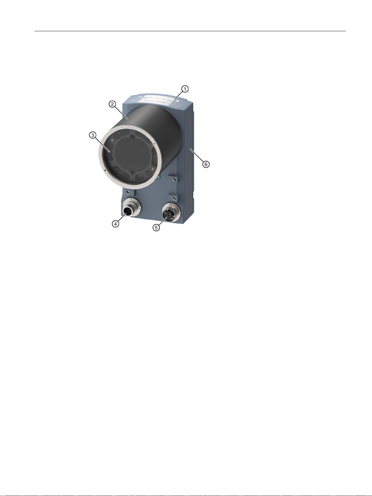
1.3
Design of the SIMATIC MV540
①
④
(M12, 12-pin)
②
⑤
Power over Ethernet (M12, 4-pin)
③
Built-in ring light
⑥
Nameplate
1.3 Design of the SIMATIC MV540
The following figure shows the design of the SIMATIC MV540 optical reader.
LED display
Protective lens barrel
Figure 1-1 Design of the SIMATIC MV540
Combination interface for
power supply, DI/DQ, RS232 and CM
Ethernet interface
SIMATIC MV500
Operating Instructions, 06/2018, C79000-G8976-C494-01
17
Description
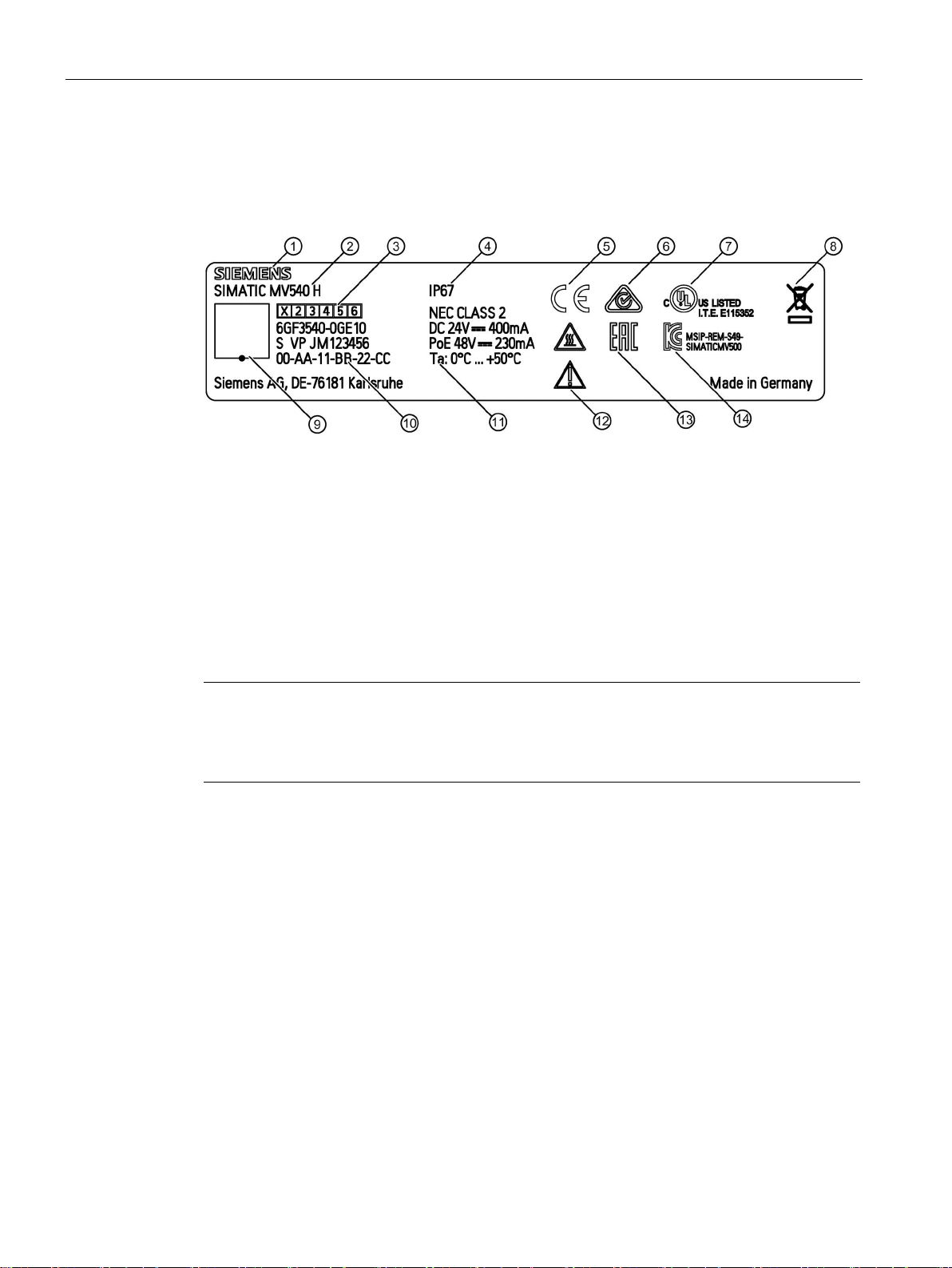
1.4
Structure of the nameplate
①
Manufacturer
⑧
Disposal label
②
Product designation
⑨
Data matrix code
③
⑩
number and MAC address (12 digits)
④
IP rating
⑪
Technical specifications
⑤
CE mark
⑫
Warning symbols
⑥
C-Tick mark
⑬
EAC marking
⑦
UL Listing mark
⑭
KCC test mark
Note
Reserved MAC address
A second MAC address is also reserved when the device supplied. This MAC address of the
specified MAC address on the nameplate +1.
1.4 Structure of the nameplate
The nameplate is located on the housing of the optical reader and shows the article number
and other important product information.
Product version of the device
Figure 1-2 Example of the SIMATIC MV540 nameplate
Article number, production code/serial
SIMATIC MV500
18 Operating Instructions, 06/2018, C79000-G8976-C494-01
Description
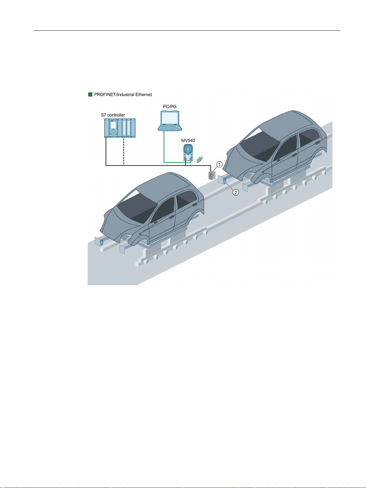
1.5
System configuration
①
Optical sensor or light barrier (for trigger signal)
②
Object with code
1.5 System configuration
The following figure shows a typical system configuration with a SIMATIC MV540 optical
reader.
Figure 1-3 Example of a system configuration on a production line (illustrated with SIMATIC MV540)
SIMATIC MV500
Operating Instructions, 06/2018, C79000-G8976-C494-01
19

Description
1.6
System components
Optical reader
PC/PG
1.6 System components
To equip an application with optical readers, you need the following hardware components:
● SIMATIC MV500 optical reader
● Lens suitable for code size and read distance
● Ring light
● Protective lens barrel
● 24 V DC, 2 A power supply (tolerance: 19.2 ... 28.8 V):
– Alternatively via I/O / CM cable
– Alternatively via Power over Ethernet
● Communication connection:
– RS232/RS422 integrated in the I/O / CM cable
– Ethernet cable
Apart from the components for operating the optical reader, you also require a PC/PG to
commission the device:
● PC/PG minimum configuration:
– Ethernet interface with at least 100 Mbps
– CPU: DualCore with 3 GHz
– RAM: 4 GB
● Software:
– Microsoft Windows 7 operating system or newer
– Web browser with HTML5 support
Tested Web browsers: Microsoft Internet Explorer as of V11, Mozilla Firefox as of V52
and Google Chrome as of V57
The system requirements of SIMATIC MV500 optical readers for communication partners in
the process depend on the selected communication connection. You can find more
information on communication connections in the section "Network and system integration
(Page 53)".
SIMATIC MV500
20 Operating Instructions, 06/2018, C79000-G8976-C494-01

Description
1.7
Functional description
Image acquisition
Web Based Management (WBM)
1.7 Functional description
The optical readers detect the object characteristics required for the task using digital image
acquisition.
Following image acquisition, the image is analyzed by a powerful digital signal processor.
Depending on the application, multilevel complex algorithms are used during the analysis:
● To find and decode the codes contained in the image.
● To verify codes.
The results of the evaluation are transferred to an automation system connected via the
communications interfaces.
The user is supported in the use of the optical reader by a variety of feedback messages:
● Live image display
● Auto-detection for code type recognition
● Result and quality preview
● Display of diagnostics images
● Warning and error messages
● 3-language online help in the optical reader
The WBM is based on Web server technology. This means that only a computer with an
Internet browser connected with an optical reader via Ethernet is necessary. The optical
reader is then called using its IP address. The display of the WBM appears in the display
window of the Internet browser. Display via Ethernet allows convenient setting and control of
all parameters of the optical reader. Operator control of the optical readers is supported by
context-sensitive online help.
If automatic adjustment does not lead to an optimum result due to special conditions, you
can use the WBM to readjust individual parameters of the optical reader manually. You can
save 15 different settings in the optical reader.
Depending on the task, up to 12 processing steps can be set as a sequence in one program.
The following processing steps are available:
● Decoder step for reading 1D/2D codes
You can store up to 15 different programs on the reader.
The settings for communication with other devices must be made in the WBM.
SIMATIC MV500
Operating Instructions, 06/2018, C79000-G8976-C494-01
21

Description
Processing
User management and access protection
Configuration via remote client
Diagnostics functions
1.7 Functional description
The actual processing is triggered by different events.
● In the simplest situation, the optical reader generates the trigger event itself. Optical
readers have an auto-trigger function for this purpose.
● Depending on the application, it may be advisable to provide the trigger event via the I/O
cable. In this case, the optical reader obtains the signal, for example, from a light barrier.
The trigger signal immediately triggers image acquisition followed by evaluation. The
result of the evaluation is then transferred to the higher-level control system through the
selected communications connection. Once the evaluation result has been transferred,
reading can be started again.
The functions of the optical reader can be protected from unauthorized access and
manipulation. The access rights can be assigned to various personified users in the form of
user roles.
The configuration of the optical reader can be backed up and restored automatically, for
example, when there is a shift change, using a connected PC. This means the validation of
your production plant can be restored at the press of a button.
The optical reader has comprehensive diagnostics functions. If incorrect readings are made,
the diagnostics functions can be used to find reasons for the errors based on the recorded
images. This is necessary, for example, if problems occurred in the prior marking process.
SIMATIC MV500
22 Operating Instructions, 06/2018, C79000-G8976-C494-01

Description
Compatibility with MV400
SIMATIC MV400
SIMATIC MV500
Digital inputs
/outputs
4 configurable DI/DQs
2 DQs
RS232 interface
DISA bit (via)
RS232, CM, TCP/IP, PN, DI
RS232, CM, TCP/IP, PN
DHCP modes
WebAPI
(incompatible with MV400)
NOTICE
Compatibility restrictions
1.7 Functional description
The functions, communication protocols and configurations are largely compatible with the
devices of the SIMATIC MV400 series. The device configurations for these devices can be
imported into the readers of the SIMATIC MV500, enabling a seamless transition from
SIMATIC MV400 to MV500.
Note that after importing an MV400 device configuration, the program must be saved again.
Table 1- 1 Differences / possible incompatibilities
DI trigger, DQ strobe,
9.6 ... 115 KB
1 ◆ 1.5 ◆ 2 stop bits
Client and server Client
✓ ✓
DI trigger, DQ strobe,
9.6 ... 115 KB
1 ◆ 2 stop bits
(CONNECT button)
The MV400 "Resolution, half" function is no longer available on MV500 due to faster image
acquisition times.
Note that software release V1.0 does not support the following functions of MV400:
• Calibrated verification (Veri-Genius license),
• Vericode
• OCR (Text Genius) and
• Locator function (Pat genius)
SIMATIC MV500
Operating Instructions, 06/2018, C79000-G8976-C494-01
23

Description
1.7 Functional description
SIMATIC MV500
24 Operating Instructions, 06/2018, C79000-G8976-C494-01

2
Qualified personnel
Proper use
Repairs
WARNING
Risk of injury/material damage
This device conforms to the pertinent safety regulations according to IEC, VDE and EN. If
you have questions about whether it is permissible to install the device in the planned
environment, please contact your service representative.
Startup and operation of the device/system in question must only be performed using this
documentation. Commissioning and operation of a device/system may only be performed by
qualified personnel. Qualified personnel as referred to in the safety guidelines in this
documentation are those who are authorized to start up, earth and label units, systems and
circuits in accordance with the relevant safety standards.
The unit may be used only for the applications described in the catalog or the technical
description, and only in combination with the equipment, components and devices of other
manufacturers where recommended or permitted by Siemens. This product can only function
correctly and safely if it is transported, stored, set up, and installed correctly, and operated
and maintained as recommended.
Repairs to the device may only be performed by authorized specialists.
Unauthorized opening or improperly performed repairs can cause considerable damage to
property or danger to users.
SIMATIC MV500
Operating Instructions, 06/2018, C79000-G8976-C494-01
25

Safety notes
System expansions
NOTICE
Invalidation of the warranty
NOTICE
Voltage can destroy electrostatic-sensitive modules
Install only system expansions that are intended for this device. Installing other expansions
can damage the system or violate the safety provisions and regulations for radio interference
suppression. You can obtain information on system expansions suitable for installation from
the technical customer service or from the sales office responsible for your area.
Any damage to the device caused by installing or replacing system expansion products will
void the warranty.
The device contains modules that are sensitive to electrostatic discharge. ESD devices can
be destroyed by voltages well below the threshold of human perception. Such voltages
occur if you touch a component or electrical connectors of a module without first
discharging the static from your body. The damage caused by overvoltage on a module
cannot normally be detected immediately and only becomes apparent after a longer period
of operation.
Measures for protecting against discharge of static electricity:
• Before working with modules, make sure that you discharge static from your body, for
example by touching a grounded object.
• The devices and tools used must also be free of static charges.
• Interrupt the power supply.
• Pick up the modules only on their edges and do not touch any pins or printed
conductors.
SIMATIC MV500
26 Operating Instructions, 06/2018, C79000-G8976-C494-01

Safety notes
Connecting the 24 V DC power supply
WARNING
Requirement: Safe extra low voltage
24 V DC power supply (19.2 to 28.8 V)
Overvoltage protection
NOTICE
Protection of the external power supply
The device should only be connected to a 24 V DC power supply which satisfies the
requirements of safe extra low voltage (SELV).
When the device is operated on a wall, in an open rack or other similar locations, an NEC
Class 2 current source is needed for compliance with UL requirements (according to
UL 60950-1). In all other cases (according to IEC/EN/DlN EN 60950-1), a current source
with limited power (LPS = Limited Power Source) is required.
The generation of the 24 V DC supply voltage by the line-side power supply must be
implemented as functional extra-low voltage with safe electrical isolation (floating)
according to IEC 80364-4-41, or as SELV according to IEC/EN/DlN EN 60950-1 and
LPS/NEC class 2.
If the optical reader is supplied via extensive supply lines or networks, interference by
strong electromagnetic pulses on the supply lines is possible, e.g. from lightning or the
switching of large loads.
The connection of the external power supply is not protected against strong
electromagnetic pulses. An external overvoltage protection module is required for this
purpose. The requirements according to EN 61000-4-5, Surge test on power supply lines,
are only met when a suitable protective element is used. A suitable device would be, for
example, the Dehn Blitzductor BVT AVD 24, article number 918 422, or a comparable
protective element.
Manufacturer:
DEHN+SOEHNE GmbH+Co.KG, Hans-Dehn-Str.1, P.O. Box 1640, D-92306 Neumarkt,
Germany
SIMATIC MV500
Operating Instructions, 06/2018, C79000-G8976-C494-01
27

Safety notes
Use in an area of plants with high-energy radiation
NOTICE
Protection of the image sensor from damaging radiation
When the SIMATIC MV500 optical reader is used in an environment of plants with highenergy radiation, for example, laser light or arcs, the image sensor of the optical reader
must be protected from damaging radiation.
The image sensor is protected by means of suitable daylight filters:
• Radiation outside the visible light spectrum (IR and UV radiation) is filtered out.
• Visible light can pass without problem.
SIMATIC MV500
28 Operating Instructions, 06/2018, C79000-G8976-C494-01

3
3.1
Code reading (1D/2D codes)
3.1.1
Area of application and examples
Two-dimensional codes
One-dimensional codes
The optical reader reads the types of code listed below.
● DMC
● PDF417
● QR
● DotCode
● Codabar
● Code 32
● Code 39 (without checksum)
● Code 39+CS (with checksum)
● Code 93
● Code 128
● EAN 8
● EAN 13
● GS1 Databar Expanded
● GS1 Databar Limited
● GS1 Databar Omnidirectional
● GS1 Databar Stacked
● Int. 2/5 (without checksum)
● Int. 2/5+CS (with checksum)
● Pharmacode
● Postnet
● UPC-A
● UPC-E
SIMATIC MV500
Operating Instructions, 06/2018, C79000-G8976-C494-01
29

Image processing
3.1.1.1
Applications for two-dimensional codes
Printed code
Laser code (plastic surface)
Laser code (pcb)
Code created with an ink jet printer.
Punched code
Data Matrix ECC080
3.1 Code reading (1D/2D codes)
Below, you can find several examples of data matrix codes, QR codes, PDF417 codes and
dot codes:
SIMATIC MV500
30 Operating Instructions, 06/2018, C79000-G8976-C494-01
 Loading...