

Siemens SIMATIC MV500 Operating Manual

SIMATIC Ident
Optical identification SIMATIC MV500
Operating Manual
05/2019
C79000
Introduction
1
Welcome screen
2
Description of the WBM
3
Start page
4
Application
5
Settings
6
Device
7
Appendix
A
SIMATIC MV500
-G8976-C495-02

Siemens AG
Digital Industries
Postfach 48 48
90026
GERMANY
Ⓟ
Copyright © Siemens AG 2018 - 2019.
All rights reserved
DANGER
indicates that death or severe personal injury will result if proper precautions are not taken.
WARNING
indicates that death or severe personal injury may result if proper precautions are not taken.
CAUTION
indicates that minor personal injury can result if proper precautions are not taken.
NOTICE
indicates that property damage can result if proper precautions are not taken.
WARNING
Siemens products may only be used for the applications described in the catalog and in the relevant technical
ambient conditions must be complied with. The information in the relevant documentation must be observed.
Legal information
Warning notice system
This manual contains notices you have to observe in order to ensure your personal safety, as well as to prevent
damage to property. The notices referring to your personal safety are highlighted in the manual by a safety alert
symbol, notices referring only to property damage have no safety alert symbol. These notices shown below are
graded according to the degree of danger.
If more than one degree of danger is present, the warning notice representing the highest degree of danger will
be used. A notice warning of injury to persons with a safety alert symbol may also include a warning relating to
property damage.
Qualified Personnel
The product/system described in this documentation may be operated only by personnel qualified for the specific
task in accordance with the relevant documentation, in particular its warning notices and safety instructions.
Qualified personnel are those who, based on their training and experience, are capable of identifying risks and
avoiding potential hazards when working with these products/systems.
Proper use of Siemens products
Note the following:
documentation. If products and components from other manufacturers are used, these must be recommended
or approved by Siemens. Proper transport, storage, installation, assembly, commissioning, operation and
maintenance are required to ensure that the products operate safely and without any problems. The permissible
Trademarks
All names identified by ® are registered trademarks of Siemens AG. The remaining trademarks in this publication
may be trademarks whose use by third parties for their own purposes could violate the rights of the owner.
Disclaimer of Liability
We have reviewed the contents of this publication to ensure consistency with the hardware and software
described. Since variance cannot be precluded entirely, we cannot guarantee full consistency. However, the
information in this publication is reviewed regularly and any necessary corrections are included in subsequent
editions.
NÜRNBERG
05/2019 Subject to change

Table of contents
1 Introduction ............................................................................................................................................. 5
2 Welcome screen ..................................................................................................................................... 7
3 Description of the WBM........................................................................................................................... 9
3.1 Layout of the WBM ................................................................................................................... 9
4 Start page ............................................................................................................................................. 15
5 Application ............................................................................................................................................ 17
5.1 Program .................................................................................................................................. 17
5.1.1 "Sequence" program step ....................................................................................................... 22
5.1.1.1 Description .............................................................................................................................. 22
5.1.1.2 Program sequence .................................................................................................................. 23
5.1.2 "Overview" program step ........................................................................................................ 23
5.1.2.1 Auto-setup ............................................................................................................................... 24
5.1.2.2 Description .............................................................................................................................. 29
5.1.3 "Image acquisition" program step ........................................................................................... 29
5.1.3.1 Auto-setup ............................................................................................................................... 29
5.1.3.2 Image ...................................................................................................................................... 30
5.1.3.3 Trigger ..................................................................................................................................... 32
5.1.3.4 Lighting ................................................................................................................................... 36
5.1.3.5 E-focus .................................................................................................................................... 37
5.1.3.6 Verification .............................................................................................................................. 37
5.1.4 "Decoder" program step .......................................................................................................... 39
5.1.4.1 Auto-setup ............................................................................................................................... 40
5.1.4.2 General ................................................................................................................................... 41
5.1.4.3 Format ..................................................................................................................................... 44
5.1.4.4 Decoding order ....................................................................................................................... 60
5.1.4.5 Decoder .................................................................................................................................. 63
5.1.4.6 Multicode ................................................................................................................................. 64
5.1.4.7 Evaluation ............................................................................................................................... 65
5.1.4.8 MATCH ................................................................................................................................... 66
5.1.4.9 N_OK....................................................................................................................................... 69
5.1.4.10 Decoder options (standard) .................................................................................................... 70
5.1.4.11 Decoder options (ID Genius) .................................................................................................. 72
5.1.4.12 Decoder options (1D) .............................................................................................................. 73
5.1.5 "Result" program step ............................................................................................................. 76
5.1.5.1 Program format text ................................................................................................................ 76
5.1.5.2 Error messages ....................................................................................................................... 89
5.1.6 Image and result display ......................................................................................................... 94
5.1.7 Image and result view ............................................................................................................. 96
SIMATIC MV500
Operating Manual, 05/2019, C79000-G8976-C495-02
3

Table of contents
6 Settings ............................................................................................................................................... 103
6.1 Communication .................................................................................................................... 103
6.1.1 Interfaces ............................................................................................................................. 103
6.1.2 Use ....................................................................................................................................... 112
6.1.3 Digital I/O ............................................................................................................................. 117
6.2 Options ................................................................................................................................. 119
6.2.1 Lighting ................................................................................................................................. 119
6.2.2 Diagnostics & monitoring ..................................................................................................... 122
6.2.3 Extras ................................................................................................................................... 126
6.3 Security ................................................................................................................................ 133
6.4 User management ............................................................................................................... 136
7 Device ................................................................................................................................................. 139
7.1 Diagnostics ........................................................................................................................... 139
7.2 System ................................................................................................................................. 142
7.3 Adapt .................................................................................................................................... 147
7.4 Help ...................................................................................................................................... 147
SIMATIC MV500
4 Operating Manual, 05/2019, C79000-G8976-C495-02

1
The MV500 optical readers are equipped with a Web server that provides Web Based
Management (WBM). Using the WBM, you can configure your readers. Among other things,
you can create reader-specific programs and program sequences and run diagnostics.
SIMATIC MV500
Operating Manual, 05/2019, C79000-G8976-C495-02
5

Introduction
SIMATIC MV500
6 Operating Manual, 05/2019, C79000-G8976-C495-02
2
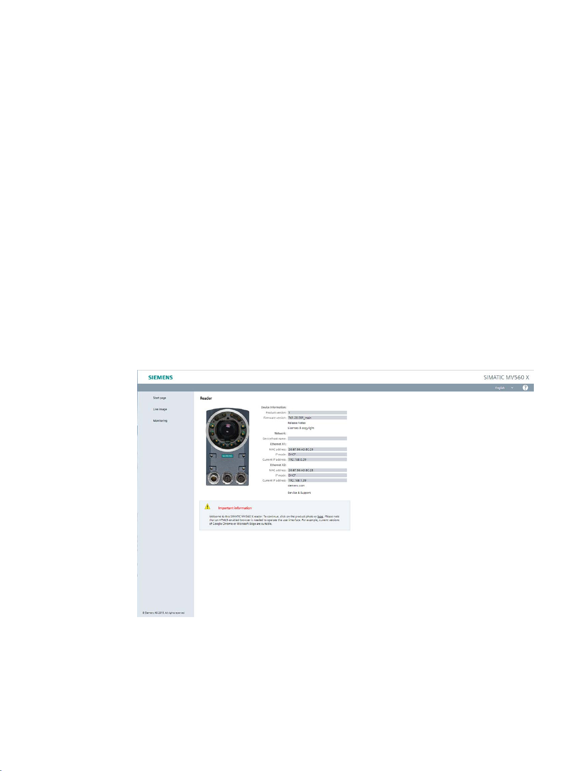
After you have called the IP address of your optical reader, a welcome screen opens. This
provides important information from the optical reader that can be integrated into numerous
environments, since HTML5 is not required for this page.
Advantages
● Independent of the operating system or the Web browser you are using.
● Does not require Java Runtime on the visualization device.
● Requires little memory and performance on the visualization device.
● Can be integrated easily into existing applications.
Available HTML pages
Once the connection to the reader has been successfully established, the WBM welcome
screen appears:
Figure 2-1 Optical reader welcome screen
SIMATIC MV500
Operating Manual, 05/2019, C79000-G8976-C495-02
7

Welcome screen
Welcome screen
Shows current device information on:
● Device reader revision level
● Firmware version
● Device/host name
● Network information of the interfaces
Start page
This menu item takes you to the Web Based Management (WBM) start page.
Live image display
Displays the images acquired by the optical reader in adjustment mode or processing mode.
If the visualization device provides Java script support, the displayed image is automatically
updated. With the displayed links, you can reach the other pages.
Monitoring
Non-embedded display of the last image processed in processing mode with colored overlay
showing the results of processing (ROIs and details view).
Requires JavaScript support and Internet Explorer as of Version 8.
SIMATIC MV500
8 Operating Manual, 05/2019, C79000-G8976-C495-02

3
NOTICE
Security recommendation: Enable user management
3.1 Layout of the WBM
Using the WBM, you can configure the SIMATIC MV500 optical readers.
After starting the WBM the first time, no user management is enabled. To make sure that
no unauthorized persons can access the reader settings, we recommend that you enable
the user management, create new user profiles and delete any existing default user profiles
after starting the WBM for the first time.
For additional information on logging in to WBM and creating/deleting user profiles, refer to
the section "User management (Page 136)".
When you have created new user profiles you need to log in with one of these user profiles
when you restart the WBM.
SIMATIC MV500
Operating Manual, 05/2019, C79000-G8976-C495-02
9
Description of the WBM
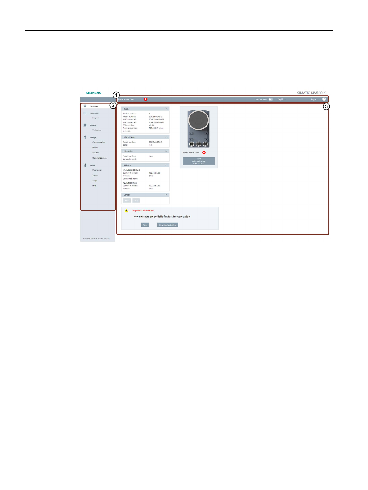
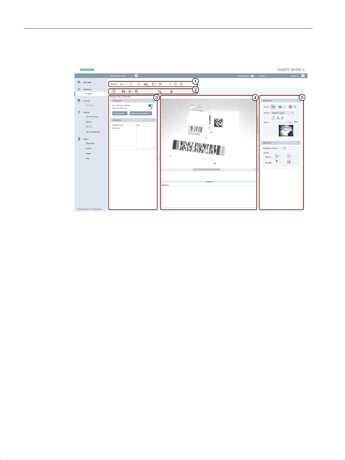
①
Status bar and toolbar
②
Menu tree
③
Main window
3.1 Layout of the WBM
Layout of the WBM
After successfully establishing a connection to the reader and switching to the start page, the
WBM start window appears:
Figure 3-1 Start page of the WBM
Status bar and toolbar ①
Above the main window, there is a status bar with the following information:
● Display of the reader status and access status
● Selection of the view
● Drop-down list for selecting the user interface language
● Display of the user profile
● Login drop-down list for login/logout on the WBM (only with active user management)
● Help
A menu-specific toolbar may be located below the status bar and above the main window.
The toolbar is only displayed in the "Application" and "Libraries" menus and has different
functions depending on the menu.
The toolbar and its individual functions are described at the start of each section related to
the menu.
SIMATIC MV500
10 Operating Manual, 05/2019, C79000-G8976-C495-02
Description of the WBM
Icon
Description
adaption".
Icon
Description
3.1 Layout of the WBM
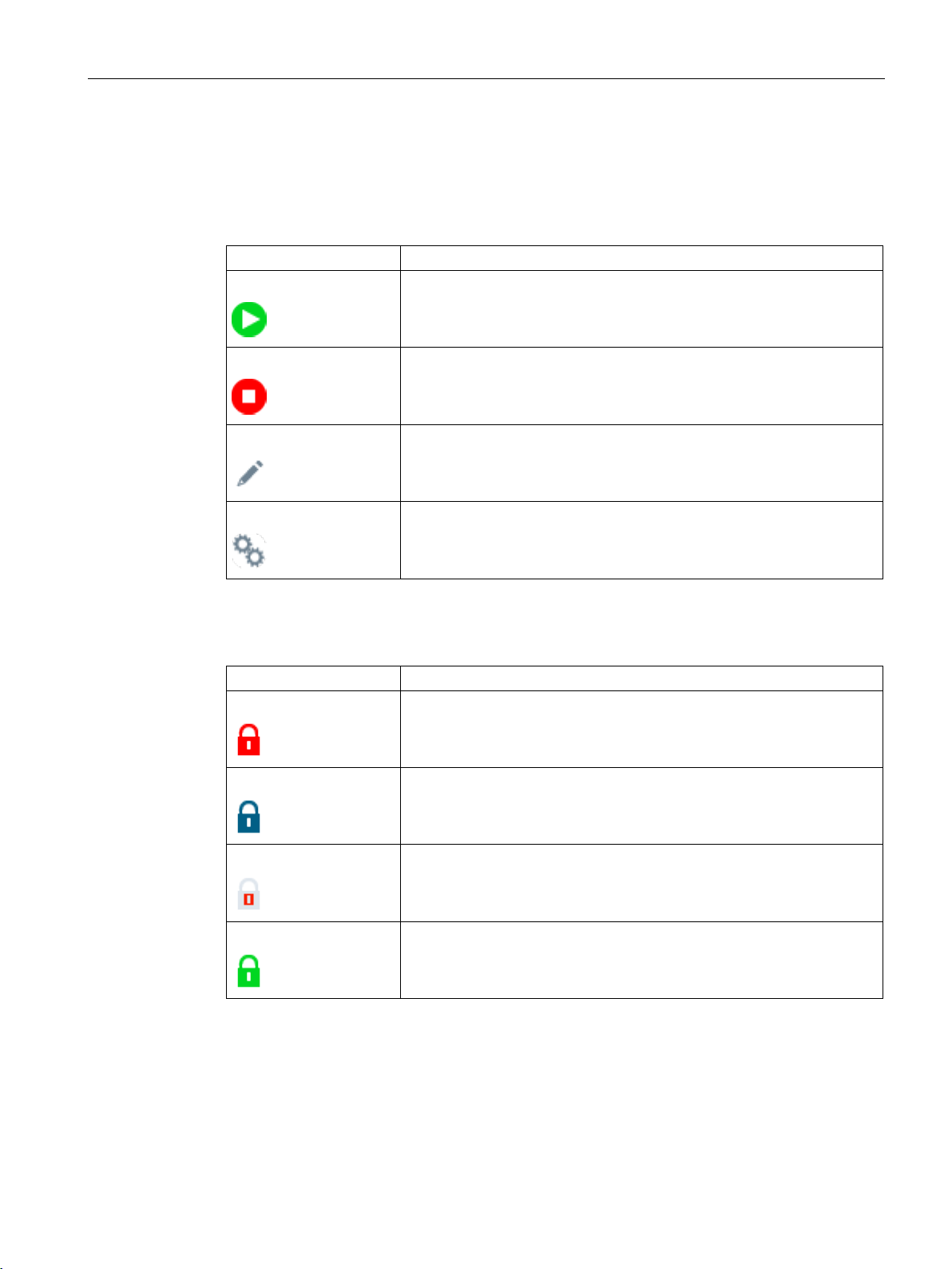
Reader status and access status
The reader status shows the current status of the reader.
Table 3- 1 Reader status
Start
Stop
Edit
Adapt
The reader has the "Start" status. This means that the device is currently
in processing mode (RUN).
The reader has the "Stop" status. This means the device is currently neither in processing mode nor in productive mode. There is no operation
(STOP).
The reader has the "Edit" status. This means the device is currently in edit
mode and changes can be made to the configuration.
The reader has the "Adapt" status. This means the device is currently in
adaption mode. This mode is started either by the "READ" button or by
the "Full program" function in the program step "Overview > Auto-
The access status shows the current status of the WBM.
Table 3- 2 Access status
Red padlock
Operation is not possible in the "Read only" status because the WBM of
another PC is currently in control of the optical reader.
Blue padlock
Red/gray padlock
Green padlock
Standard view
Use the Standard view to switch between Standard and Extended view. In the Standard
view, the operator controls that are not required for standard applications are grayed out. If
the Standard view is disabled, extended parameters are released for editing.
SIMATIC MV500
Operating Manual, 05/2019, C79000-G8976-C495-02
The logged-on user is not authorized to change settings.
DISA is active. Only users that have the "Take control" right are capable
of taking over control of the optical reader from the controller.
The currently logged on user has taken control of the optical reader.
11

Description of the WBM
Menu items
Functions
Application
Libraries
Verification
Editing verification library
Communication
Specifying communication settings
Options
Specifying general device settings
Security
Assigning role-specific rights
3.1 Layout of the WBM
Login area
If user management ("Settings > User management") is switched on, you must log on in this
area to be able to make changes in the WBM with your login.
Help
You use the question mark symbol "?" to open the WBM online help. The help is contextsensitive. The corresponding help page for the menu in which you are currently working is
called.
Menu tree ②
The menu tree with the different menu items is located in the left margin of the WBM. The
currently selected menu item is highlighted in color.
The following table provides an overview of the menu items and the functions they provide.
Table 3- 3 The menu structure of the WBM
Start page
Program
Settings
User management
• Retrieving device and network information
• Starting/stopping processing mode of existing programs
• Specifying and testing image acquisition settings, reader orientation and
processing task
• Monitoring/controlling processing
• Enabling/disabling user management
• Creating and deleting user profiles
• Changing passwords
SIMATIC MV500
12 Operating Manual, 05/2019, C79000-G8976-C495-02

Description of the WBM
Menu items
Functions
Device
Adapt
Specifying settings for the WBM view
3.1 Layout of the WBM
Diagnostics
System
Help
Main window ③
• Displaying and backing up diagnostic data from reader
• Creating system image including diagnostics
• Treatment for persistent diagnostics
• Resetting reader to factory settings
• Saving/restoring device configuration
• Updating the firmware
• Saving/restoring custom GUI
• Further help on the WBM and the devices
• Readme
• "Service & Support" contact information
If you are logged in to the WBM as a "User", some menu items can only be used with certain
restrictions. You will find a list of the restrictions in the section "User management
(Page 136)".
The main window shows the contents of the selected menu items. Here, you can configure
the various menu-dependent parameters. The main window is divided up into three columns
in the menu items "Application" and "Libraries".
Message area
The message area displays all WBM-related error messages and warnings (e.g. transfer
errors). If messages or warnings are present, they are displayed at the bottom of the main
window. Note that the message area is only displayed on the start page of the WBM.
SIMATIC MV500
Operating Manual, 05/2019, C79000-G8976-C495-02
13

Description of the WBM
3.1 Layout of the WBM
SIMATIC MV500
14 Operating Manual, 05/2019, C79000-G8976-C495-02
4
Group
Description
Internal lamp
Information about the built-in internal ring light is displayed in this group.
E-focus lens
This group displays information about the built-in lens.
Network
This group displays network information about the Ethernet interfaces.
Control
You can start and stop the processing mode in this group.
Icon
Description
The "Start page" menu contains device and network information as well as information on
the installed internal ring light.
Table 4- 1 "Start page" menu groups
Reader This group shows the following device information:
• Product version
• Article number
• MAC address
• FPGA version
• Firmware version
• Licenses
If messages or warnings are present, they are displayed below the groups in the main
window of the start page.
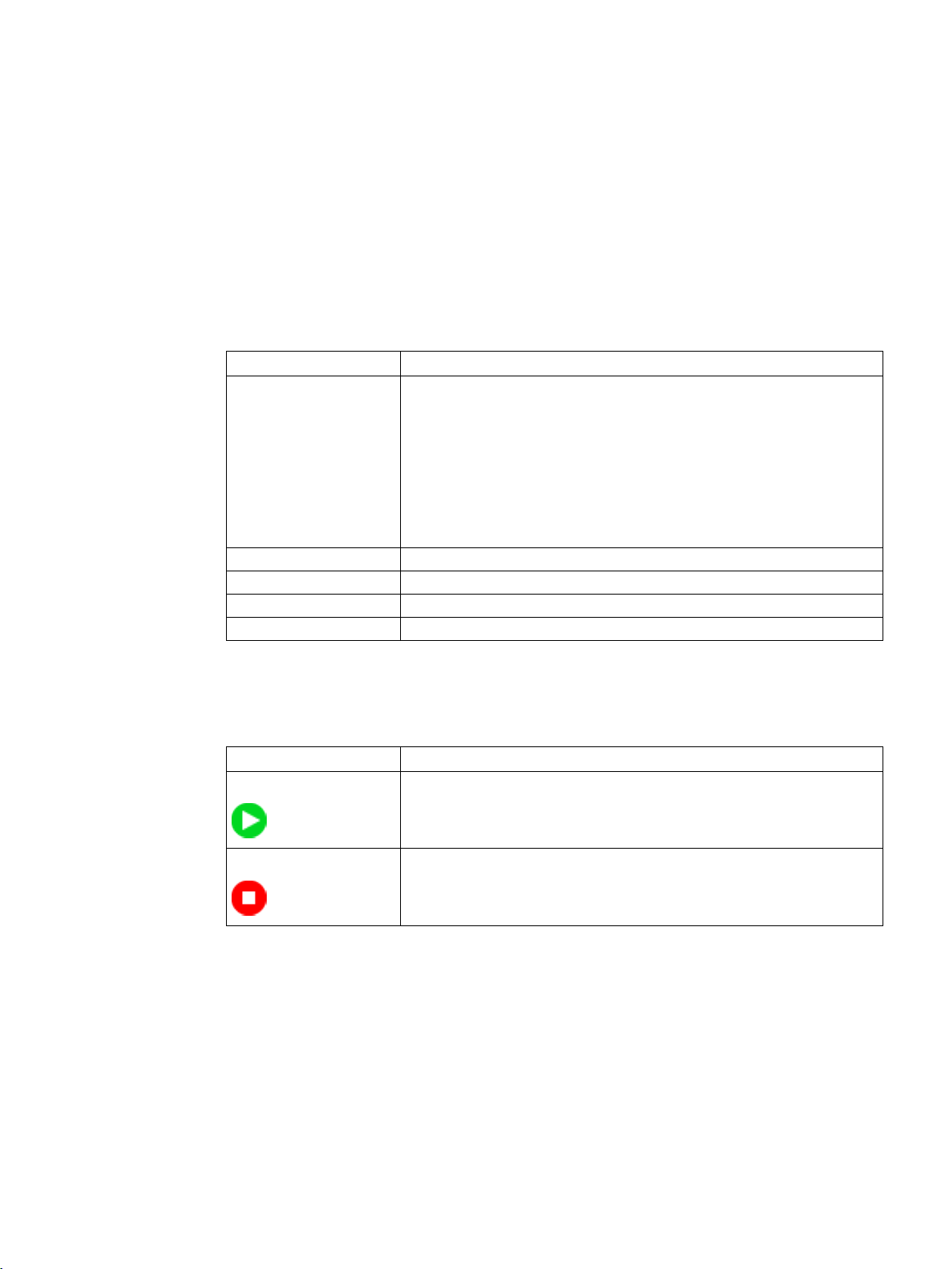
Table 4- 2 Reader status
Start
Stop
The reader has the "Start" status. This means that the device is currently
in processing mode (RUN).
The reader has the "Stop" status. This means the device is currently neither in processing mode nor in productive mode. There is no operation
(STOP).
Button: Start automatic setup of READ function
Using the "Start automatic setup" button, you can automatically adapt all relevant program
settings. This function is identical to the function performed by the "READ" button on the
optical reader.
SIMATIC MV500
Operating Manual, 05/2019, C79000-G8976-C495-02
15

Start page
Automatic disconnection on inactivity
Note that a timer runs in the background of the start page. After 5 minutes of inactivity, the
connection to the reader is automatically terminated. This ensures that the connection to the
reader is not blocked by an inactive user and is shared with other users.
A few seconds before automatic disconnection, a dialog window appears informing the user
of the upcoming disconnection.
This function is only active on the start page and is automatically reset by operator input.
SIMATIC MV500
16 Operating Manual, 05/2019, C79000-G8976-C495-02

5
5.1 Program
The "Program" menu gives you the option of setting the type of processing that the optical
reader executes in one cycle. This task is the main task of the WBM and offers a wide range
of options. These options enable you to adjust the optical reader to suit a wide range of
reading tasks in line with your requirements.
The "Program" menu includes the following functions:
● Creating, editing, saving and deleting programs
Functions during program creation:
– Image acquisition control functions
– Selection of lighting
– Configuration of reading tasks - divided into a sequence of max. 12 reading steps
– Output formatting of results
– Selecting a verification
● Program selection
● Starting processing
● Checking settings and results in processing mode
SIMATIC MV500
Operating Manual, 05/2019, C79000-G8976-C495-02
17
Application
①
"Program" toolbar
②
Program steps & program-specific toolbar
③
Parameter area
④
Image and result display
⑤
Image and result view
5.1 Program
Structure of the "Program" menu
Figure 5-1 Structure of the "Program" menu
SIMATIC MV500
18 Operating Manual, 05/2019, C79000-G8976-C495-02
Application
Button
Description
Program sequence part of the toolbar 1)
Sequence
Select the program sequence you want to start.
General part of the toolbar
Program
Select the program you want to start.
5.1 Program
Description of the toolbars
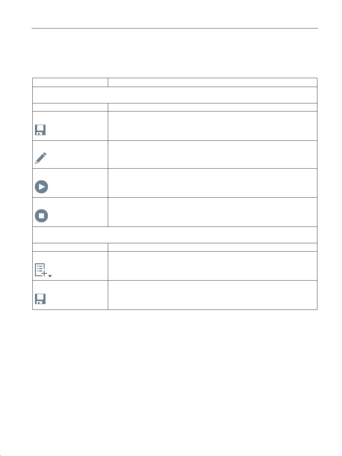
Table 5- 1 "Program" toolbar ①
Save sequence
Edit program
Start sequence
Stop sequence
New element
Click this button to save the selected program sequence ("Sequence" drop-down list).
Click this button to edit the selected program ("Program" drop-down list).
Click this button to start the selected program sequence ("Program" drop-down list).
Click this button to stop the selected program sequence ("Program" drop-down list).
Click this button to create a new program. You can also create new programs based on
existing programs (copy of "xx").
Save program
SIMATIC MV500
Operating Manual, 05/2019, C79000-G8976-C495-02
Click this button to save the selected program ("Program" drop-down list).
19
Application
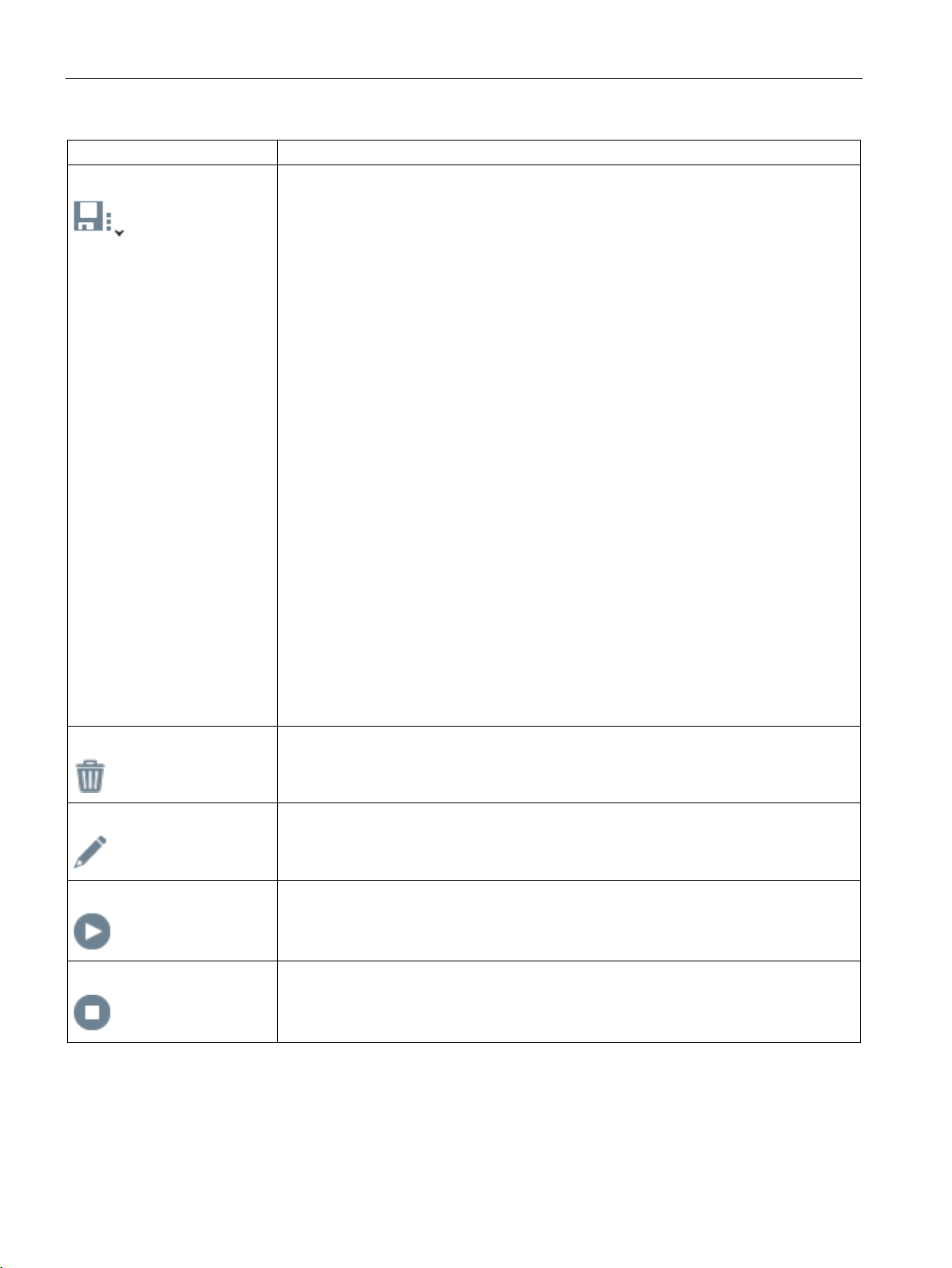
Button
Description
Click this button to close the menu without applying the changes.
1)
under "Settings > Options > Extras > Program sequence".
5.1 Program
Save program as
• Number
In this text box, enter the program number under which you want to save the current
program.
Value range: 1 ... 15
• Name
In this text box, enter the name under which you want to save the current settings and
the program. This entry is optional.
Possible values: Letters, numbers and underscores. Maximum of 255 characters.
• Comment
In this text box, you can enter your own program-specific information, for example.
Among other things, this is intended to make it easier for you to identify the individual
programs.
• Wait for next image acquisition
Select this check box when you do not want to save the current image but the next
image.
• Save program as
Click this button to save the current settings and the program with the specified name.
• Discard changes
Click this button to discard the changes you have made since the program was saved
last. If the program was newly created and has not been saved since, it will not be
saved and will be lost.
• Cancel
Delete program
Click this button to delete the selected program ("Program" drop-down list).
Edit program
Click this button to edit the selected program ("Program" drop-down list).
Start program
Click this button to start the selected program ("Program" drop-down list).
Stop program
Click this button to stop the selected program ("Program" drop-down list).
Note that the program sequence part of the toolbar is only shown when the "Program sequence" option was activated
SIMATIC MV500
20 Operating Manual, 05/2019, C79000-G8976-C495-02
Application
Button
Description
5.1 Program
Automatic memory function in case of connection interruptions
If a connection is lost, the last program changes made are temporarily buffered. This
program is automatically displayed when the connection is re-established. The number after
the program name "Modified" indicates which program was open and modified during the
interrupted connection.
You may wish to save these changes immediately, since the changes will be lost if the
connection is terminated again or the program is changed.
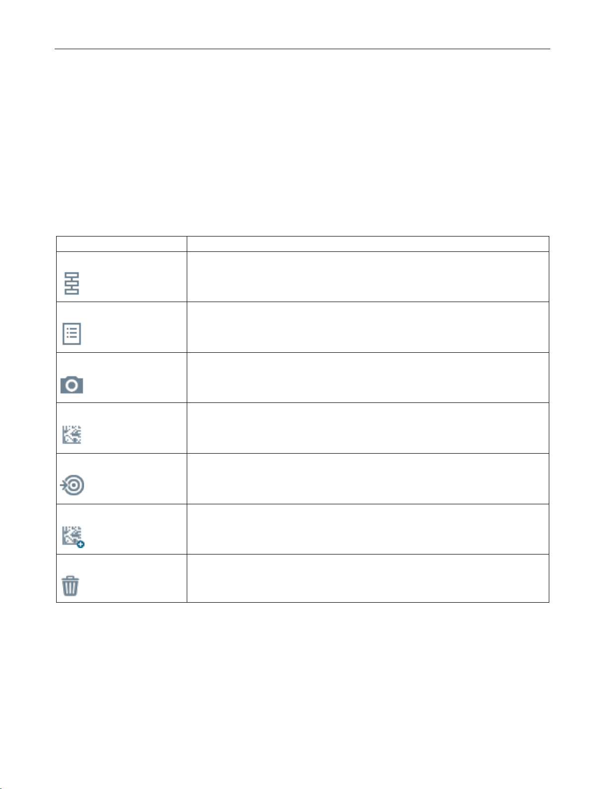
Table 5- 2 Program steps & program-specific toolbar ②
Program sequence
Program
Image acquisition
Decoder step
Result
Add decoder step
Click this button to go to the "Program sequence" program step.
Click this button to go to the "Program" program step.
Click this button to go to the "Image acquisition" program step.
Click this button to go to the "Decoder step" program step.
Click this button to go to the "Result" program step.
Use a drag-and-drop operation to move this button to the desired position to add an additional decoder step.
Delete decoder step
SIMATIC MV500
Operating Manual, 05/2019, C79000-G8976-C495-02
Use a drag-and-drop operation to drag the decoder step you want to delete to the "Delete
decoder step" icon to delete the decoder step.
21

Application
Column
Description
Left column
Note: Identical for all program steps.
Note: Identical for all program steps.
Menu command or
parameter
Description
255 characters.
4000 characters.
5.1 Program
Description of the page layout with three columns
Table 5- 3 Page layouts
Parameter area ③
Image and result display ④
Center column
Image and result view ⑤
Right column
The various program step-specific parameters are shown in this column.
This column shows the image that was acquired last or the current image as well as the
associated results
The settings for the image and result display are shown in this column. If the reader is in
processing mode ("Start") or in Auto-setup, additional information is displayed.
5.1.1 "Sequence" program step
Note that this program step is only shown when the "Program sequence" option under
"Settings > Options > Extras" was enabled.
You can combine multiple programs into one program sequence in this program step.
5.1.1.1 Description
Table 5- 4 Description
Sequence name In this input box, you can assign a name to the sequence.
Possible values: Letters, numbers and ASCII special characters. Maximum of
Comment In this input box, you can enter your own sequence-specific information, for
example. Among other things, this is intended to make it easier for you to identify
the individual sequences.
Possible values: Letters, numbers and ASCII special characters. Maximum of
SIMATIC MV500
22 Operating Manual, 05/2019, C79000-G8976-C495-02

Application
Menu command or
parameter
Possible values
Default
Description
left mouse button + Ctrl.
image acquisition settings stored in this program.
5.1 Program
5.1.1.2 Program sequence
Table 5- 5 Program sequence
Programs contained
Use 1st image On/Off Off Turn on this parameter to use an image acquisi-
1 ... x 1 Select the programs that the program sequence
should use. You can select the programs with the
tion with the acquisition settings of the first program sequence contained in the program. Using
the acquired image, processing is attempted with
all the programs selected in the "Programs contained" parameter.
If the parameter is disabled, separate image acquisition is carried out for each program selected
in the "Programs contained" parameter with the
5.1.2 "Overview" program step
The program overview provides you with information about the currently selected program
and you are given the option of having the parameters assigned automatically or making the
settings manually.
SIMATIC MV500
Operating Manual, 05/2019, C79000-G8976-C495-02
23

Application
Menu command or
parameter
Description
ommended for uneven object holders.
The adaption step is shown in the right column (image and result view).
or have them adapted automatically.
5.1 Program
5.1.2.1 Auto-setup
The Auto-setup functions assist you in the parameter assignment of a new or existing
program. You have the option of having the parameters assigned automatically or making
the settings manually.
Table 5- 6 Auto-setup
Fast code type
detection
Fast focus detection
You use this parameter to specify whether or not Fast code type detection is to
be performed for the subsequent adaptation. You define the default setting for
this parameter in the menu "Settings > Options > Extras > Operation on the
device".
On: Code type detection is automatically performed for the following code types
if decoder steps are present in the source program:
• DMC (with set decoder type)
• Available 1D codes (except pharma code)
Off: Complete code type detection for the following code types is performed for
each decoder step:
• DMC (with currently set decoder type)
• PDF417
• Available 1D codes (except pharma code)
• QR
• DMC (with decoder type "ID-Genius", if not already done in step 1 and com-
patible with other settings)
You use this parameter to specify whether or not Fast focus detection is to be
performed for the subsequent adaptation. You define the default setting for this
parameter in the menu "Settings > Options > Extras > Operation on the device".
On: With focus detection, the image display or ROI area is not subdivided into
subROIs. This means that lighting and focus are not checked and adjusted for
each individual subROI. This setting shortens this process step. Recommended
for even, flat object holders.
Off: The image display or ROI area is divided into subROIs. This means that
lighting and focus are checked and adjusted for each individual subROI. Rec-
Full program Automatically executes all adaption/program steps of the program. This may
take some time.
Note: This function is the same function that is triggered with the "READ" button
on the reader.
Step-by-step
adaption
SIMATIC MV500
Guides you through the program settings step-by-step. You can follow this adaption through all adaption/program steps and either set the parameters manually
24 Operating Manual, 05/2019, C79000-G8976-C495-02

Application
5.1 Program
Automatic adaption with the help of the "Full program" function
The "Full program" function is similar to the function of the "READ" button. Both functions
automatically adapt the reader, but differ in some points.
Requirements
● To use the function, you need a code in the target area of the reader. Use the image
display to ensure that the code is located in the target area of the reader.
Default settings
Before starting the "Full program" function, you can define some settings which are adopted
by the automatic adaptation. These settings can shorten the duration of the function or
disable unwanted options. You can specify the following settings in advance:
● Fast code type detection
● Fast focus detection
● Set the lighting (flash or continuous light / "Image acquisition > Lighting")
● Set number of codes to read ("Decoder > Multicode")
● Define decoder steps for the codes to be expected
● Define subROIs for the expected codes
Function description
When the function is started, the reader changes to "Adaption" status, automatically
optimizes the various settings and adjusts the parameters accordingly. Automatic adaption
goes through the following phases:
1. Structure analysis
In this phase, the image area defined by the exposure ROI is divided into subROIs if
needed. The exposure and focus are set individually for each subROI. Finally, the 3 best
results - subROIs with the best sharpness values - are selected and transferred to the
next phase.
2. Decoding
In this phase, a search for code is conducted in several cycles with different filters,
sharpness values and exposures based on the result from the 1st phase. Cycles with
different setting combinations are run until a code is recognized. As soon as a code is
found in one of the cycles, the result is transferred to the next phase.
3. Optimization
In this phase, the focus and exposure are optimized again for the code type adopted from
the 2nd phase and the specified settings. Finally, the various lamp settings and image
enhancement procedures (filters) are performed again with these optimized settings to
ensure that the best read quality is achieved with the filter used.
The result of the best read quality is selected as the final result for this adaptation.
If automatic adaptation is started via the "READ" button of the reader, an alignment phase is
performed before the structural analysis. In the alignment phase, you can also align the
reader without the image display.
SIMATIC MV500
Operating Manual, 05/2019, C79000-G8976-C495-02
25

Application
5.1 Program
When adaption is complete, the reader automatically switches to edit mode ("Edit").
Depending on the result of the adaptation, the following steps are performed:
● NOK
The status display shows a message with detailed information and further instructions on
the adaptation result and the possible causes for "NOK".
● OK
The reader switches to the "Result" program step and enables formation of result. The
status display shows a message with detailed information and further instructions on the
adaptation result. The changes are applied to the currently selected program. To save
these changes, you must manually save them in the desired target program.
SIMATIC MV500
26 Operating Manual, 05/2019, C79000-G8976-C495-02
Application
Overall progress
This column displays the progress or current status of the automatic adaptation.
"READ" button.
highlighted in the graph.
which settings were used in which cycle.
5.1 Program
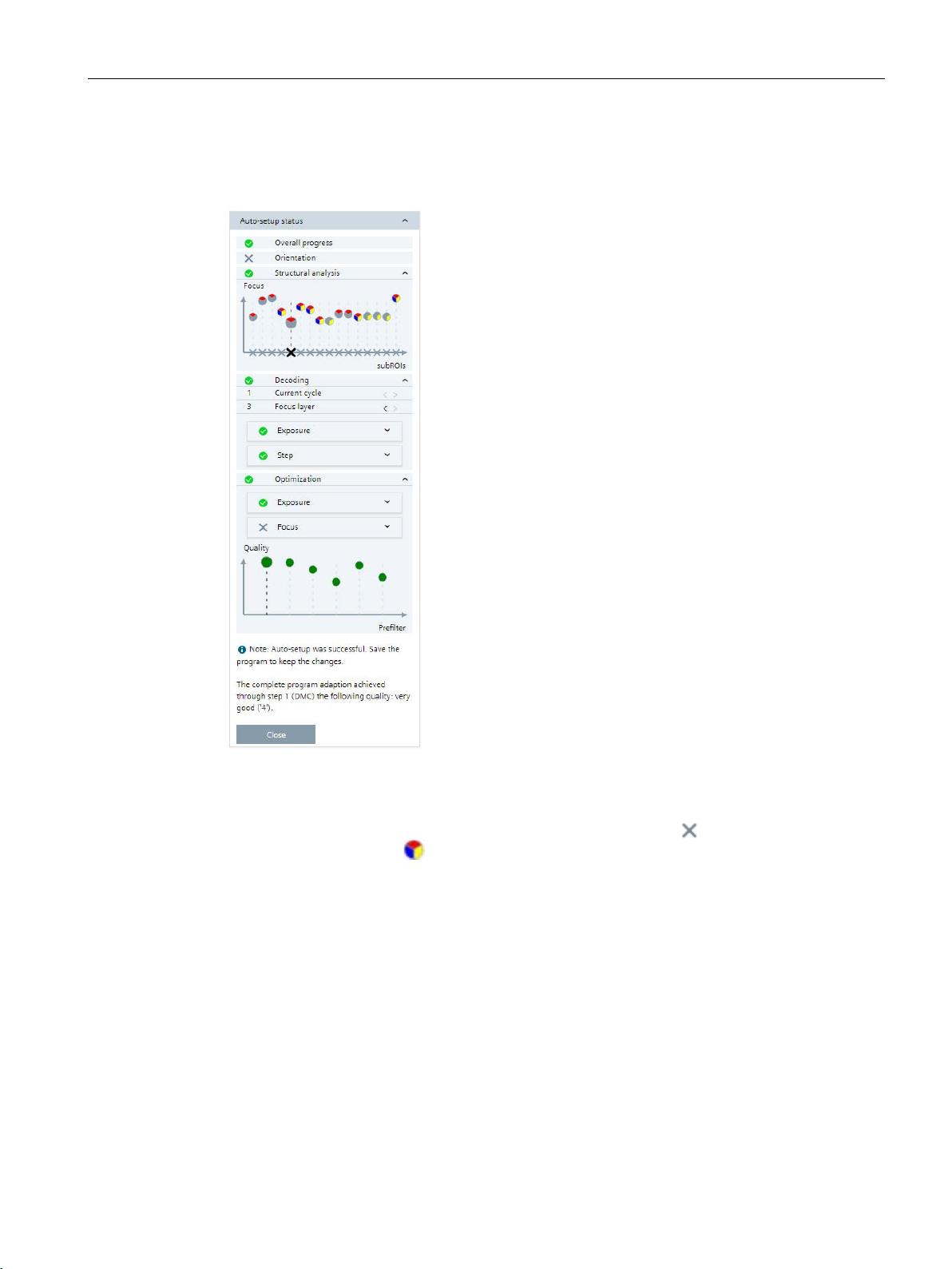
Description of the status display
The following is an example of the auto-setup status display.
Position The alignment phase only occurs if you have started the adaptation using the
Structure analysis This graph shows the distance values of the focus ( ), as well as the sharpness
values (
are described in the following table.
The information on the far left of the graph refers to the subROI at the top left, the
information on the far right of the graph refers to the subROI at the bottom right.
During the structural analysis, the corresponding subROIs are highlighted in the
graph and in the image.
When the structural analysis is finished, the subROI with the best read quality is
Decoding In this column, you can see the step currently being run during the decoding
phase of the adaptation. Once automatic adaptation is completed, you can check
SIMATIC MV500
Operating Manual, 05/2019, C79000-G8976-C495-02
) for the individual subROIs. The meanings of the sharpness symbols
27
Application
quality results were achieved in the optimization phase with which filter.
tions on the achieved adaptation result are displayed in the note field.
Icon
Description
5.1 Program
Optimization In this column, you can see the step currently being run during the optimization
phase of the adaptation. Once automatic adaptation is completed, you can check
the optimizations that have been made to the focus and exposure for the code
type found.
The quality graph displays the read qualities ("Overall quality") from the optimization phase. Move the mouse over the individual points of the graph to check which
Note field Once automatic adaptation is completed, detailed information and further instruc-
Figure 5-2 Sample status display of an auto-setup
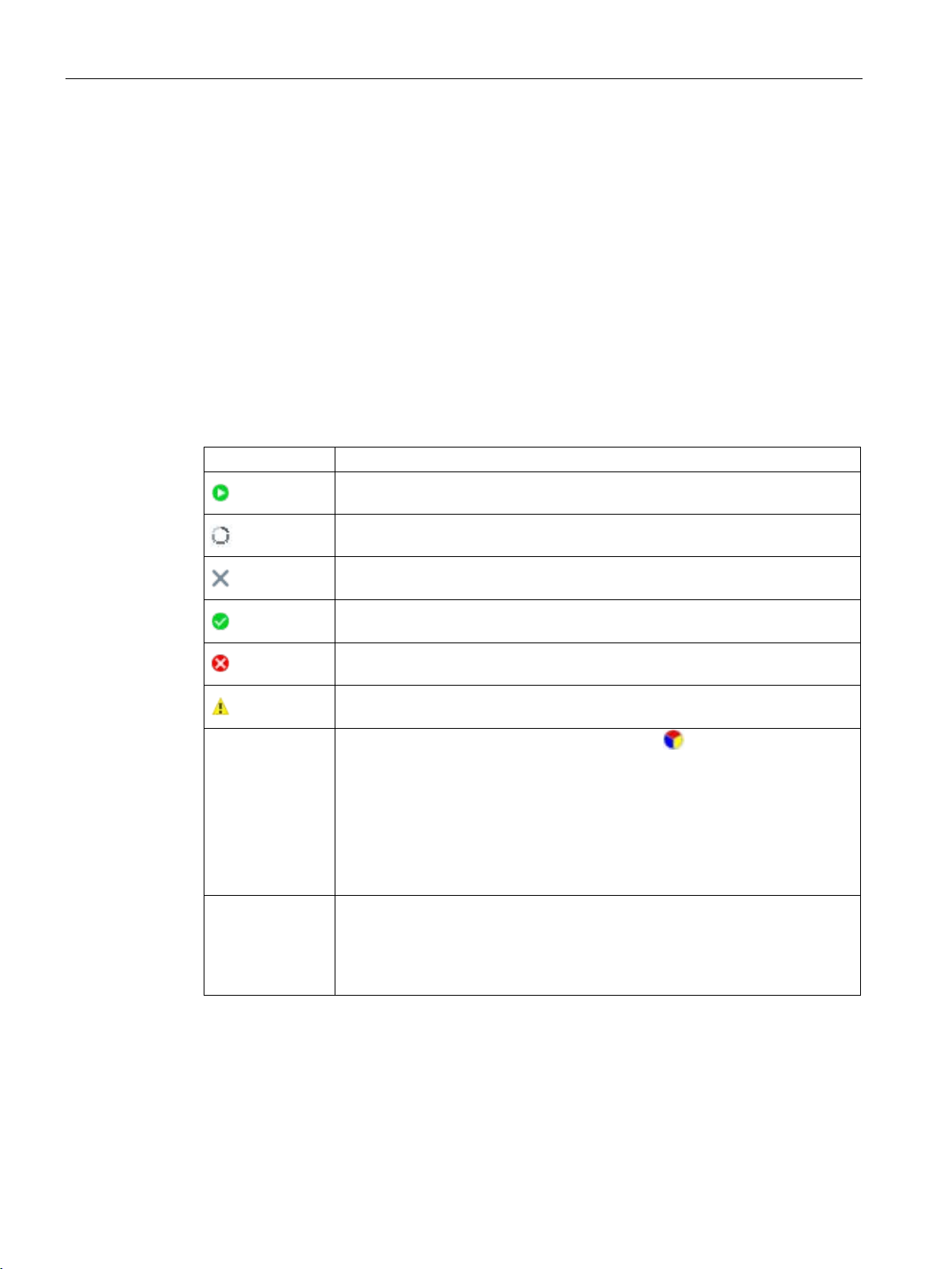
The symbols that appear in the auto-setup status display are described below.
Table 5- 7 Symbols of the status display and graphs
Structure analysis
graph
Quality graph Detailed information on the read quality ("Overall quality"):
Indicates that this phase is in progress.
Indicates that this phase is still waiting to run.
Indicates that this phase has been disabled and will not be run.
Indicates that this phase has been successfully completed ("OK").
Indicates that this phase has not been successfully completed ("NOK").
Indicates that this phase was aborted with an error.
Detailed information about the sharpness symbols :
• 3-segment circle: One or more segments of the internal ring light were used.
– Blue: The main beam segment was switched on.
– Red: The unpolarized light segment was on.
– Yellow: The polarized light segment was on.
• White circle: An external lamp was used.
• Black circle: No lamp was used.
• Green: Good
• Yellow: Sufficient
• Red: Bad
SIMATIC MV500
28 Operating Manual, 05/2019, C79000-G8976-C495-02

Application
Menu command or
parameter
Description
255 characters.
4000 characters.
Button
Description
area.
Focus
You use this button to adjust the focus ("Focus" area)
5.1 Program
5.1.2.2 Description
Table 5- 8 Description
Program name In this input box, you can assign a name to the program.
Possible values: Letters, numbers and ASCII special characters. Maximum of
Comment In this input box, you can enter your own program-specific information, for ex-
ample. Among other things, this is intended to make it easier for you to identify
the individual programs.
Possible values: Letters, numbers and ASCII special characters. Maximum of
5.1.3 "Image acquisition" program step
You start setting up the reader in this program step and make all settings that have an effect
on the image acquisition.
This includes the following settings, among others:
● Auto-setup
● Image
● Trigger
● Lighting
● E-focus
● Verification
5.1.3.1 Auto-setup
The Auto-setup functions assist you in the parameter assignment of a new or existing
program. You have the option of having the parameters assigned automatically or making
the settings manually.
In this area, you can use the three buttons to have the WBM automatically make the basic
settings and set the basic orientation of the reader.
Table 5- 9 Auto-setup
Light You use this button to automatically adapt the settings of the "Image" and "Lighting"
You use the "Back" and "Next" buttons to either return to the previous program step or
switch to the next program step.
SIMATIC MV500
Operating Manual, 05/2019, C79000-G8976-C495-02
29

Application
Parameter
Possible values
Default
Description
Auto
Manual
Note
tion according to ISO/IEC 29158.
pared to normal sensitivity.
5.1 Program
5.1.3.2 Image
In this group, you enter the parameters for image acquisition.
Table 5- 10 Image
Exposure
• Auto
• Manual
Auto Setting the exposure control:
With this setting, each processing is preceded by a series of
image acquisitions so that the reader can set the optimum
brightness.
Position the Region of Interest (ROI exposure) of the image
so that the image area to be processed is included. Exposure
control is then based on this ROI.
To enable optimal operation of the brightness control, the
object to be processed must remain inside the ROI after the
trigger until exposure control is finished. The processing time
increases accordingly, whereby the cycle time and the high
limit of the cycle time include this increase in the processing
time.
To rule out reflections, use a limited ROI in this case.
Set a high limit for the exposure time and brightness in this
setting. Depending on your application it maybe necessary to
specify a high limit for the exposure time, for example, to
prevent excessive blurring due to movement.
The "A" button is hidden.
With this setting, you specify the exposure time and brightness manually. This allows you to set the exposure according
to your own experience in conditions when the automatic
function might fail.
This setting is necessary for short image acquisition times,
for example at high reading speeds.
When you click the "A" button, you trigger a single adaption.
The reader calculates suitable values for the exposure time
and brightness. With this as a basis, you can then fine tune
the settings.
If the trigger comes during the image acquisition when automatic exposure control is active, it is ignored and an "N_OK"
is output.
Read the note on the use of the exposure ROI with verifica-
High sensitivity
SIMATIC MV500
• Off
• On
30 Operating Manual, 05/2019, C79000-G8976-C495-02
Off The "On" setting increases the light sensitivity by a factor of 4
compared to the "Off" setting.
This setting therefore is especially useful for applications with
high movement speeds or poor lighting conditions. The increased light sensitivity causes a greater pixel noise com-
 Loading...