

Page 1
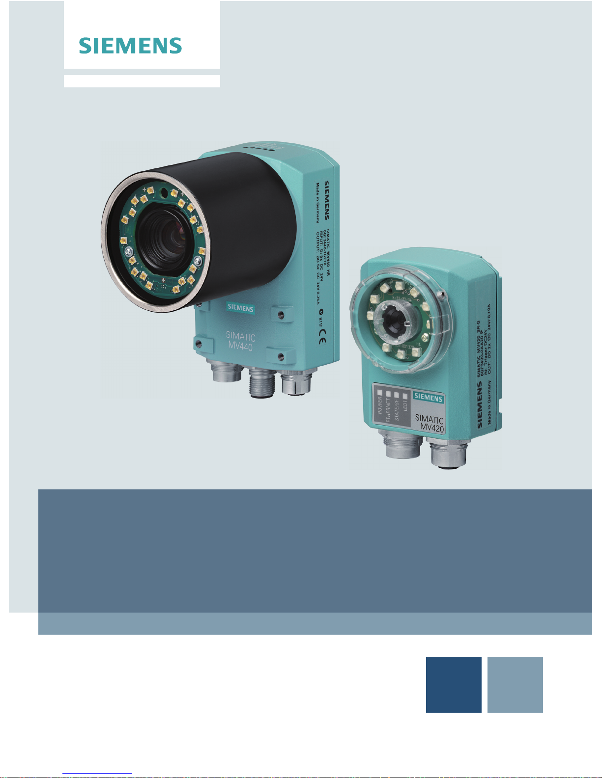
Compact Operating Instructions
SIMATIC Ident
Code Reader Systems
SIMATIC MV420 / SIMATIC MV440
04/2013Edition
Answers for industry.
Page 2

Page 3
© Siemens AG 2009 - 2013. All rights reserved
A5E02370910-06, 04/2013
1
SIMATIC Ident
Code Reader Systems
SIMATIC MV420/SIMATIC MV440
Compact Operating Instructions
Legal information
Warning notice system
This manual contains notices you have to observe in order to ensure your personal safety, as well as to prevent damage to property. The
notices referring to your personal safety are highlighted in the manual by a safety alert symbol, notices referring only to property damage
have no safety alert symbol. These notices shown below are graded according to the degree of danger.
DANGER
indicates that death or severe personal injury will result if proper precautions are not taken.
WARNING
indicates that death or severe personal injury may result if proper precautions are not taken.
CAUTION
indicates that minor personal injury can result if proper precautions are not taken.
NOTICE
indicates that property damage can result if proper precautions are not taken.
If more than one degree of danger is present, the warning notice representing the highest degree of danger will be used. A notice warning of
injury to persons with a safety alert symbol may also include a warning relating to property damage.
Qualified Personnel
The product/system described in this documentation may be operated only by personnel qualified for the specific task in accordance with
the relevant documentation, in particular its warning notices and safety instructions. Qualified personnel are those who, based on their
training and experience, are capable of identifying risks and avoiding potential hazards when working with these products/systems.
Proper use of Siemens products
Note the following:
WARNING
Siemens products may only be used for the applications described in the catalog and in the relevant technical documentation. If products
and components from other manufacturers are used, these must be recommended or approved by Siemens. Proper transport, storage,
installation, assembly, commissioning, operation and maintenance are required to ensure that the products operate safely and without any
problems. The permissible ambient conditions must be complied with. The information in the relevant documentation must be observed.
Page 4

SIMATIC MV420/SIMATIC MV440
2 A5E02370910-06, 04/2013
1 Security messages
Note
For its automation and drives product portfolio, Siemens provides IT security mechanisms to support secure operation of the
plant/machine. Our products are continuously being further developed also taking into account the aspect of IT security. We
therefore recommend that you regularly check for updates of our products and that you only use the latest versions. You will
find information on this topic under:
Industrial Security (http://www.siemens.com/industrialsecurity
)
Here, you can register for a product-specific newsletter.
For the secure operation of a plant/machine, it is also necessary to integrate the automation components in a full IT security
concept for the entire plant/machine that represents the state of the art in IT technology. You will find notes on this topic
under:
Industry Online Support (http://support.automation.siemens.com/WW/llis
api.dll?func=cslib.csinfo2&aktprim=99&lang=en)
Products from other manufacturers that are being used must also be taken into account.
Page 5
SIMATIC MV420/SIMATIC MV440
A5E02370910-06, 04/2013
3
2 Installation
Installing SIMATIC MV420/SIMATIC MV440
These readers are compact standalone devices that, when mounted in a suitable location, need only be equipped with a
lens, a power supply cable, and a communications link. The SIMATIC MV440 reader has four threaded holes
(SIMATIC MV420: two threaded holes) each on the front and back, which allows flexible mounting.
Installing the reader with protective lens housing
To provide lighting when reading the codes, you have several options available. The simplest and most economical option in
terms of space is the ring light integrated in the lens protective housing.
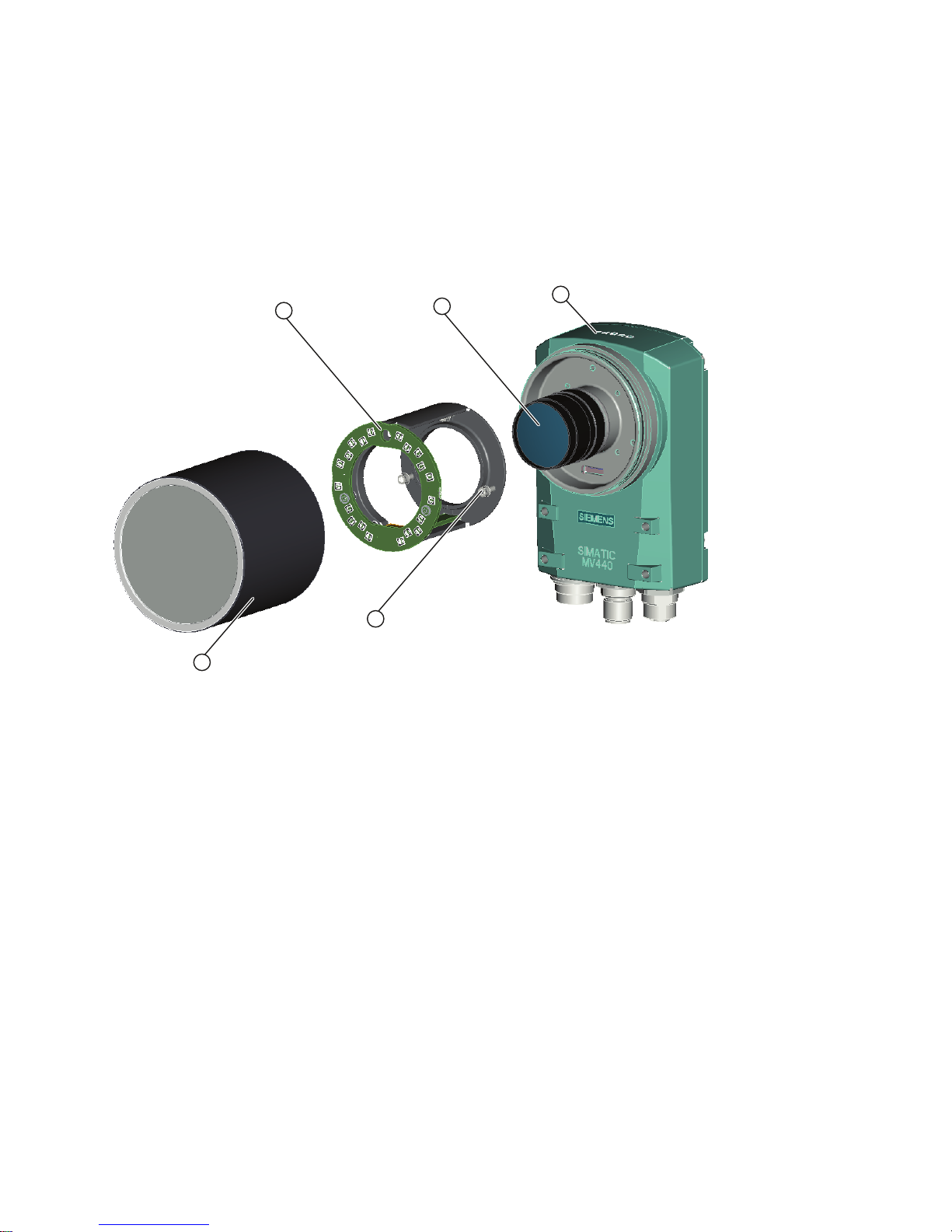
① Built-in ring light ④ M2.5 hexagon socket head screws
② Lens ⑤ Protective lens housing ∅ 65
③ Reader
Figure 2-1 Mounting the SIMATIC MV440 reader with a protective lens housing and built-in ring light
Page 6
SIMATIC MV420/SIMATIC MV440
4 A5E02370910-06, 04/2013
3 Connecting
Connect the reader to the components of your application.
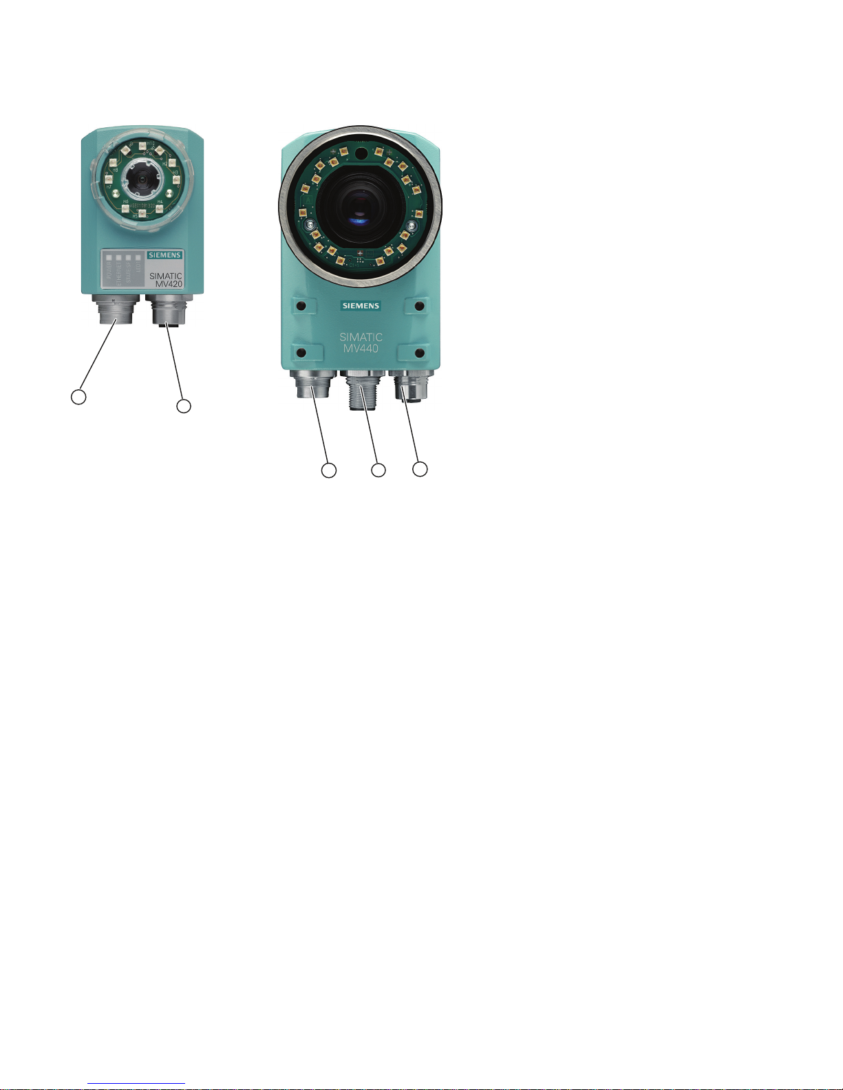
① Combined cable socket for the power supply, I/O connectors, ASM and RS-232
② Ethernet socket
③ Combined socket for the power supply, I/O terminals, and RS-232
④ ASM socket
⑤ Ethernet socket
Figure 3-1 Cable sockets for SIMATIC MV420 (left) and SIMATIC MV440 (right)
Power IO RS-232 cable
The power IO RS-232 cable is used for the power supply, to connect to the digital I/O connectors and, for example, for the
communications interface of a programmable controller via the RS-232 interface. The pinout of the Power IO RS-232 cable
is provided in the table below.
Page 7

SIMATIC MV420/SIMATIC MV440
A5E02370910-06, 04/2013
5
Pinout of Power IO RS-232 cable
NOTICE
INPUT - COMMON or OUTPUT - COMMON must be connected
To be able to use the inputs and outputs described below, it is imperative that the INPUT - COMMON or OUTPUT COMMON is connected.
Table 3-1 SIMATIC MV440
Pin Color Signal name Possible values Default setting Meaning
H red 24 V DC Power supply
G blue 0 V Power supply
K violet INPUT1 TRG TRG Trigger input
D yellow INPUT /
OUTPUT2
DISA, SEL0, SEL1, SEL2, SEL3, TRN,
RES, IN_OP, TRD, RDY, READ,
MATCH, N_OK, EXT_1, EXT_2,
EXT_3, EXT_4
IN_OP Freely selectable input
or output.
L Gray/
pink
INPUT /
OUTPUT3
DISA, SEL0, SEL1, SEL2, SEL3, TRN,
RES, IN_OP, TRD, RDY, READ,
MATCH, N_OK, EXT_1, EXT_2,
EXT_3, EXT_4
RDY Freely selectable input
or output.
C green INPUT /
OUTPUT4
DISA, SEL0, SEL1, SEL2, SEL3, TRN,
RES, IN_OP, TRD, RDY, READ,
MATCH, N_OK, EXT_1, EXT_2,
EXT_3, EXT_4
READ Freely selectable input
or output.
B brown INPUT /
OUTPUT5
DISA, SEL0, SEL1, SEL2, SEL3, TRN,
RES, IN_OP, TRD, RDY, READ,
MATCH, N_OK, EXT_1, EXT_2,
EXT_3, EXT_4
N_OK Freely selectable input
or output.
A white INPUT -
COMMON
Reference point, 0 V or
24 V for inputs.
E gray OUTPUT -
COMMON
P-type inputs/outputs:
INPUT - COMMON = 0 V and
OUTPUT - COMMON = + 24 V DC
N-type inputs/outputs:
INPUT - COMMON = + 24 V DC and
OUTPUT - COMMON = 0 V
Reference point, 0 V or
24 V for outputs.
J black STROBE
(OUTPUT)
Signal output for
connecting external
strobe lights
F pink RS-232 TXD RS-232 send line
M red/blue RS-232 RXD RS-232 receive line
Page 8

SIMATIC MV420/SIMATIC MV440
6 A5E02370910-06, 04/2013
Table 3-2 SIMATIC MV420
Pin Color Signal name Possible values Default setting Meaning
H Red 24 V DC Power supply
G Blue 0 V Power supply
K violet INPUT1 TRG TRG Trigger input
D yellow OUTPUT2 IN_OP, TRD, RDY, READ, MATCH,
N_OK, EXT_1, EXT_2, EXT_3, EXT_4
RDY Freely selectable output.
L Gray/
pink
OUTPUT3 IN_OP, TRD, RDY, READ, MATCH,
N_OK, EXT_1, EXT_2, EXT_3, EXT_4
READ Freely selectable output.
C green ASM TxD_N TxD_N signal from ASM
interface
B brown ASM TxD_P TxD_P signal from ASM
interface
A white INPUT -
COMMON
Reference point, 0 V or
24 V for inputs.
E Gray OUTPUT -
COMMON
P-type inputs/outputs:
INPUT - COMMON = 0 V and
OUTPUT - COMMON = + 24 V DC
N-type inputs/outputs:
INPUT - COMMON = + 24 V DC and
OUTPUT - COMMON = 0 V
Reference point, 0 V or
24 V for outputs.
J Black STROBE
(OUTPUT)
Signal output for
connecting external
strobe lights
F pink RS232 TxD or
ASM RxD_P
RS232 TxD, ASM RxD_P RS-232 TXD RS232 send line or
ASM RxD_P from ASM
interface
M red/blue RS232 RxD or
ASM RxD_N
RS232 RxD, ASM RxD_N RS-232 RXD RS232 receive line or
ASM RxD_N from ASM
interface
MV400 push-pull power cable assignment
Table 3-3 MV400 push-pull power cables with order numbers 6GF3400-1BH20 and 6GF3400-0BH15
Power interface (socket)
Port Wire color Signal
H Red/Orange 24 V
G Black/brown 0 V
Page 9
SIMATIC MV420/SIMATIC MV440
A5E02370910-06, 04/2013
7
ASM cable
The connectors are already fitted to the ASM cable.
● You connect the communication modules, for example RF180C and ASM456, using the ASM cable.
For SIMATIC MV420, a special ASM cable with M16 socket is available.
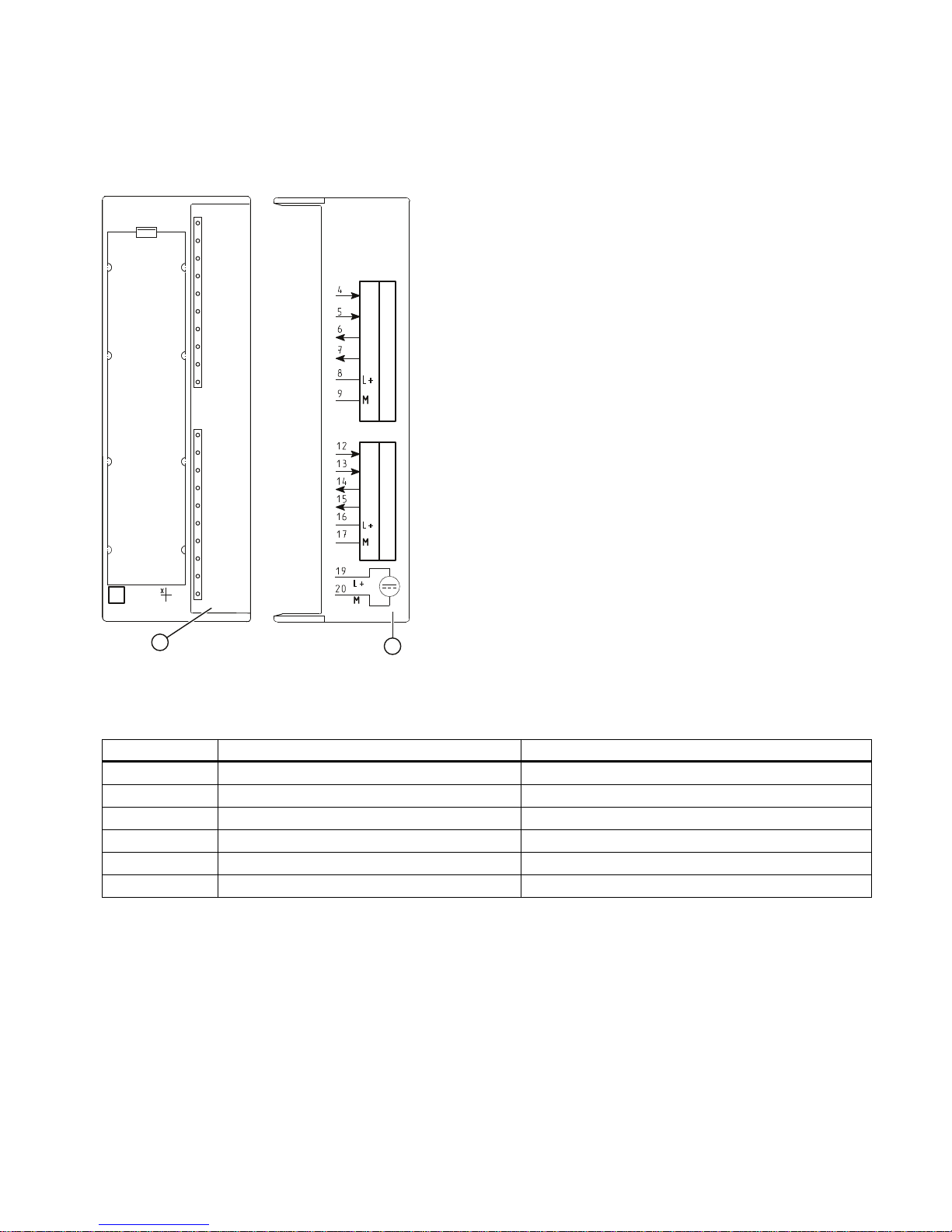
The follow cable assignment is defined for connecting to the ASM 475 module:
6
6
(
(
6
6
(
(
$60
6)
'&9
$&7B
(55B
35(B
5['B
$&7B
(55B
35(B
5['B
02%<
*7*$
6/*6/*
① Status and error displays
② Connection diagram; the numbers of the connection relate to the X1 connector on the top of the housing
Figure 3-2 Front cover and inside of the front door of the ASM 475 module
Pin M16 socket Wire color of the connecting cable Connection terminal ASM475 (channel 1/channel 2)
H Red 8 / 16
G Blue 9 / 17
F Pink 4 / 12
M Red/blue 5 / 13
B Brown 6 / 14
C Green 7 / 15
Ethernet cable M12/RJ-45
● With a preassembled Ethernet cable, you connect a PC/PG to control and operate the reader.
● Connect the Ethernet cable to a switch to link the reader to an automation system via onboard PROFINET IO.
Page 10

SIMATIC MV420/SIMATIC MV440
8 A5E02370910-06, 04/2013
4 Commissioning
To commission the device, you require a PC that meets the following requirements:
● Operating system Windows XP Professional SP 1 or higher
● Internet browser with Java Runtime Environment as of V1.2
– The user interface is optimized for display with Microsoft Internet Explorer 8 and Java Runtime Environment V.1.7.x.
● SIMATIC Primary Setup Tool (PST) is installed.
● There is a network connection via Ethernet TCP/IP.
Note
● Java Runtime Environment is also known as:
– Java Runtime
– Runtime Environment
– Runtime
– JRE
– Java Virtual Machine
– Virtual Machine
– Java VM
– JVM
– VM or
– Java Download.
Whenever possible use the latest Java version. You can find information on this topic on the Internet under
(www.java.com
), or ask your system administrator.
● You will find the Primary Setup Tool (PST):
– In your SIMATIC installation
– On the product CD of the reader
– As a free download on the SIMATIC Support Internet pages
(http://support.automation.siemens.com/WW/view/en/19440762
).
Steps for initial commissioning
Step Activity
1 Connect the reader and PC using an Ethernet cable.
2 Turn the reader on.
3 Configure the Ethernet connection between reader and PC.
4 Start the user interface with the Internet Explorer.
5 Adjust the reader using the user interface.
Note
The user interface of the reader is known as the setup support. The setup support takes the form of a Java applet stored on
the reader and this can be activated using an Internet browser.
Page 11
SIMATIC MV420/SIMATIC MV440
A5E02370910-06, 04/2013
9
Step 1
Connect the reader and PC using an Ethernet cable
Connect the reader directly to your PC/programming device over an Ethernet cable.
Note
You do not need a crossover cable because the reader is capable of autocrossing and automatically detects the type of
cable you are using.
Step 2
Turn the reader on
Turn on the power supply for the reader. The reader is supplied with power either via a connected ASM cable or via the
power IO RS232 cable or PoE cable; see also chapter Connecting (Page 4).
● Each time it is started, the rea
der runs a self-test which is indicated by the Power LED flashing.
● After a period of between several seconds and 2 minutes, the self-test is completed and the Power LED lights up
permanently in green. The reader is ready for operation
Step 3
Configure the Ethernet connection between the reader and PC
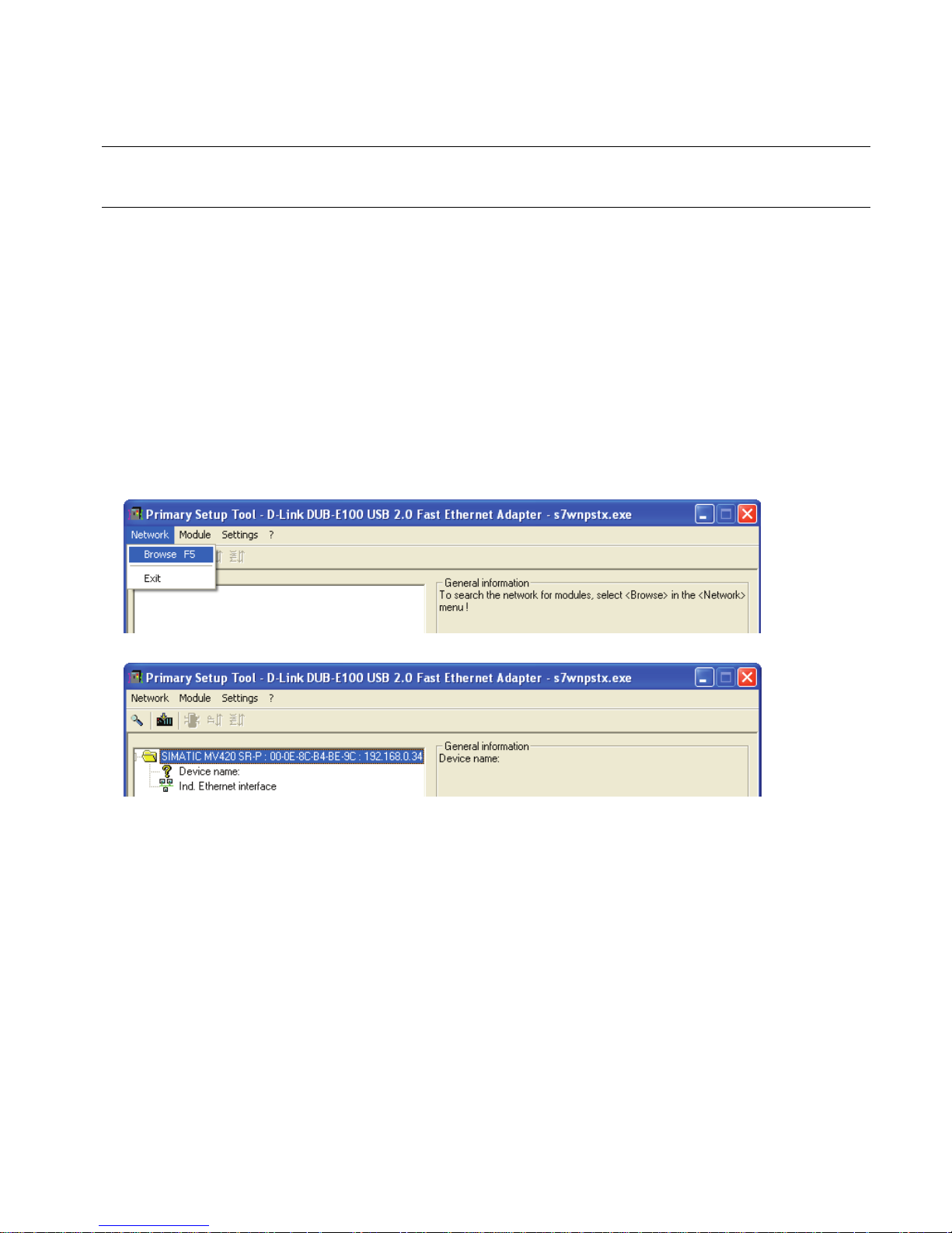
1. Start the Primary Setup Tool (Start menu ➜ Start ➜ SIMATIC ➜ Primary Setup Tool ➜ Primary Setup Tool).
2. Start the network browsing function in the PST menu (Network ➜ Browse).
3. Select the displayed device and double-click on it.
4. Clicking on the displayed Ethernet interface displays the properties of the interface.
Page 12
SIMATIC MV420/SIMATIC MV440
10 A5E02370910-06, 04/2013
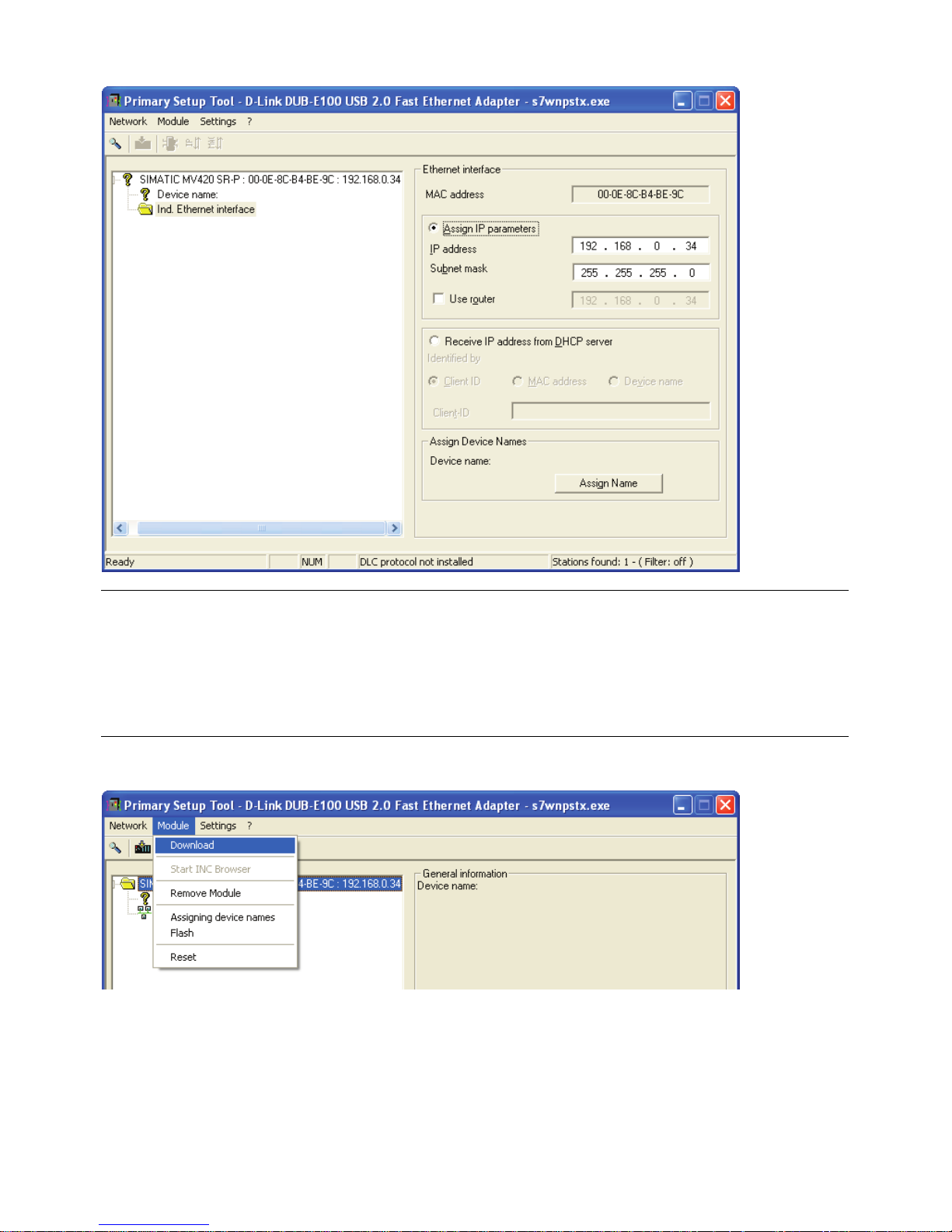
5. Select "Assign IP parameters" and enter the values for the IP address and subnet mask as shown below.
Note
IP address 192.168.100.100
● Using the IP address 192.168.100.100, the reader is configured as a DHCP server at the same time, which means
that a connected PC can obtain an IP address from the reader. By manually assigning addresses that differ from this
IP address and that are not 0.0.0.1, you configure a static IP address for the reader. PCs operated in a network are
usually configured as DHCP clients and obtain their IP addresses from a server.
● If your PC network is configured differently or you do not know how your PC is configured, check with your system
administrator.
6. Now select the MV440 or MV420 module again and then load the configuration on the reader by clicking the "Download"
menu command in the "Module" menu
Page 13
SIMATIC MV420/SIMATIC MV440
A5E02370910-06, 04/2013
11
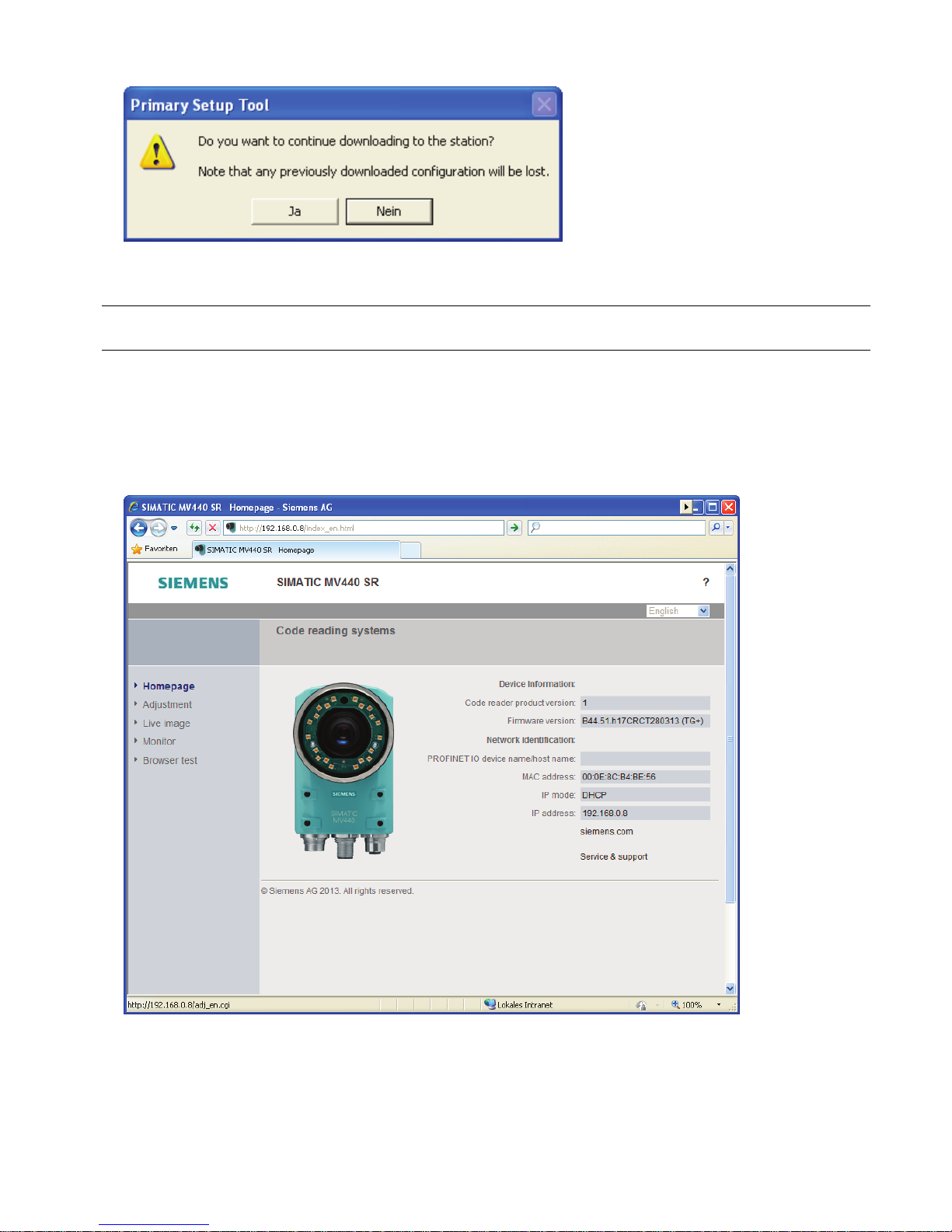
7. Confirm the following message by clicking the "Yes" button.
Result
The reader now has the manually assigned IP address 192.168.0.34 and can be reached under this address by your PC.
Note
Depending on the mode being used, you may need to restart the reader by turning the power off and on again.
Step 4
Starting the user interface
1. Open Internet Explorer and enter the IP address of the reader in the address bar.
2. Confirm with the Enter key.
The home page of the reader is loaded.
3. Now click on the image of the reader or the "Adjustment " menu command.
The user interface of the reader opens after a short loading time.
Page 14
SIMATIC MV420/SIMATIC MV440
12 A5E02370910-06, 04/2013
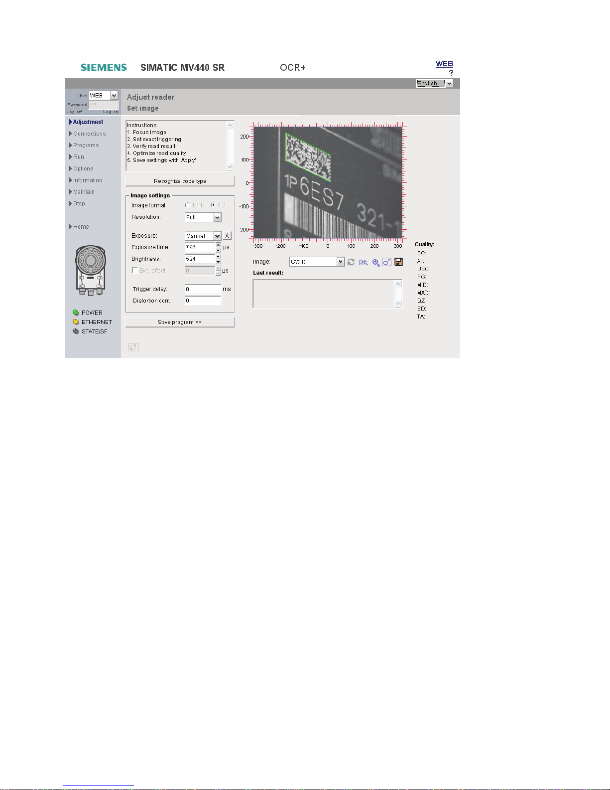
4. This is followed by the Adjustment page of the user interface in the Internet Explorer.
Result
● You are now connected to the reader and can operate it via the user interface.
● You can now perform the next step and adjust the reader and display the first read results.
● You can also get further support by clicking the "?" button at the top right. This opens the online help.
Page 15
SIMATIC MV420/SIMATIC MV440
A5E02370910-06, 04/2013
13
Step 5
Aligning the reader
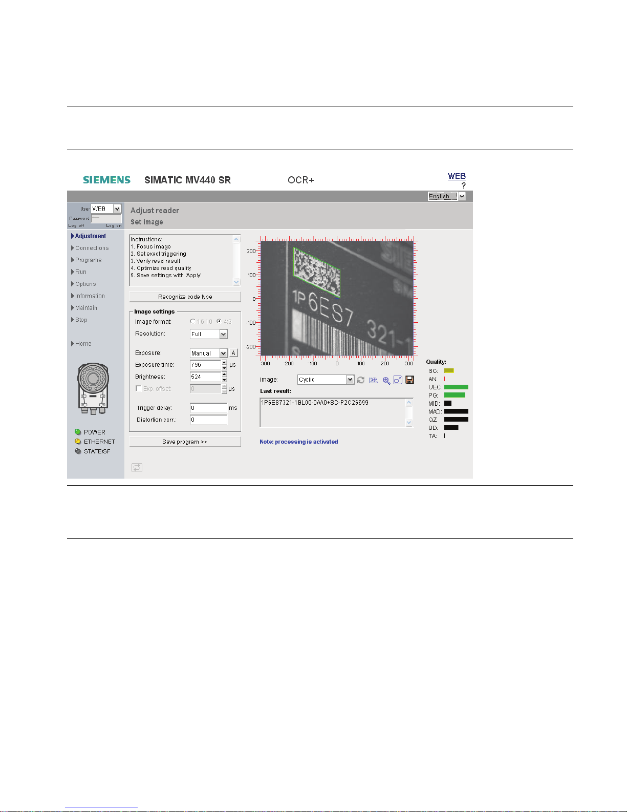
Before you put the reader into productive operation, you must first align it correctly. You do this with the user interface by
selecting the "Adjust sensor" menu command. The dialog window shows you an image as seen by the reader.
Note
Focusing the image (SIMATIC MV440 only)
To be able to focus the image, you may need to loosen the fixing screws on the lenses.
Note
Access to online help via the "?" button
Each screen of the setup support has a "?" button at the top right with which you can open the online help at any time. The
help text of the online help relevant to the currently displayed dialog then opens.
1. Position the reader so that the code to be read appears in the center of the image and is focused sharply.
The reader automatically attempts to recognize a data matrix code and decode it. You can recognize a successful read
by the green frame around the code. The more precise the triggering and the greater the contrast in the code, the higher
the read reliability will be.
Page 16

SIMATIC MV420/SIMATIC MV440
14 A5E02370910-06, 04/2013
2. If necessary, correct these settings:
– The exposure settings
– If you wish to read an EAN13 code instead of a data matrix code, for example, press the button "Recognize code".
The reader starts code type recognition and remembers the code type found for later read processes.
– In order to find the correct image acquisition time for moved objects, correct the trigger settings.
– To rectify strong irregularities through the optics (rarely necessary), correct the distortion.
Note
If exposure = Auto, the code must be completely in the image after the triggering until the automatic exposure is
completed (approximate value: 50 to 100 ms).
3. If you make modifications, save your new settings by clicking the "Apply" button.
Result
You have successfully commissioned the reader. You can now read codes for your application. You can now make specific
settings and save them under individual programs.
For more details, refer to SIMATIC MV420/SIMATIC MV440 Operating Instructions.
Page 17

SIMATIC MV420/SIMATIC MV440
A5E02370910-06, 04/2013
15
5 Documentation and service
Documentation for SIMATIC MV420 and SIMATIC MV440
Documentation Content
Documentation CD
SIMATIC MV420/SIMATIC MV440
6GF3440-8FA
● SIMATIC MV420/SIMATIC MV440 Operating Instructions
● SIMATIC MV420 / SIMATIC MV440 Compact operating instructions
● Online help
● Sample programs for FB79 for communication over PROFINET IO
● Sample program for archiving of diagnostics information
SIMATIC MV420 / SIMATIC MV440
Compact operating instructions
Step-by-step instructions for fast initial commissioning
Available from
Free download from the Internet
SIMATIC MV420 (http://support.automation.siemens.com/WW/view/en/39620218/133300)
SIMATIC MV440 (http://support.automation.siemens.com/WW/view/en/33391594/133300
)
SIMATIC Manual Collection on DVD
SIMATIC Manual Collection (http://support.automation.siemens.com/WW/v
iew/en/4073541)
All manuals for S7-200/300/400, C7, LOGO!, SIMATIC DP, PC, PG, STEP 7, ENGINEERING software, RUNTIME software,
PCS 7, SIMATIC HMI, SIMATIC NET, SIMATIC MACHINE VISION, SIMATIC SENSORS
● in 5 languages
● Order number: 6ES7998-8XC01-8YE0
Technical Support
You can contact Technical Support for SIPLUS HCS systems as follows:
● Phone: + 49 (0) 911 895 5900
● E-mail (mailto:technical-assist
● Internet: Online support request form: (http://www.siemens.com/automation/support-request)
Trademarks
All names identified by ® are registered trademarks of Siemens AG. The remaining trademarks in this publication may be trademarks whose
use by third parties for their own purposes could violate the rights of the owner.
Disclaimer of Liability
We have reviewed the contents of this publication to ensure consistency with the hardware and software described. Since variance cannot
be precluded entirely, we cannot guarantee full consistency. However, the information in this publication is reviewed regularly and any
necessary corrections are included in subsequent editions.
Siemens AG
Industry Sector
Postfach 48 48
90026 NÜRNBERG
SIMATIC MV420/SIMATIC MV440
A5E02370910-06, 04/2013
Page 18

Siemens AG
Industry Sector
Sensors and Communication
P.O. Box 48 48
90026 Nürnberg
GERMANY
Subject to change without prior notice
A5E02370910-06
© Siemens AG 20 09-2013
Get more information
www.siemens.com/simatic-ident
Industrielle
Schalttechnik
SIRIUS
www.siemens.com/automation
 Loading...